EP2236997A1 - Method for quantifying hole flow rates in film cooled parts - Google Patents
Method for quantifying hole flow rates in film cooled parts Download PDFInfo
- Publication number
- EP2236997A1 EP2236997A1 EP10157405A EP10157405A EP2236997A1 EP 2236997 A1 EP2236997 A1 EP 2236997A1 EP 10157405 A EP10157405 A EP 10157405A EP 10157405 A EP10157405 A EP 10157405A EP 2236997 A1 EP2236997 A1 EP 2236997A1
- Authority
- EP
- European Patent Office
- Prior art keywords
- film
- measuring
- thermal response
- cooling hole
- flow rate
- Prior art date
- Legal status (The legal status is an assumption and is not a legal conclusion. Google has not performed a legal analysis and makes no representation as to the accuracy of the status listed.)
- Withdrawn
Links
- 238000000034 method Methods 0.000 title claims abstract description 54
- 238000001816 cooling Methods 0.000 claims abstract description 58
- 230000004044 response Effects 0.000 claims abstract description 58
- 230000001052 transient effect Effects 0.000 claims abstract description 35
- 239000012530 fluid Substances 0.000 claims abstract description 27
- 238000012512 characterization method Methods 0.000 claims abstract description 18
- 238000005259 measurement Methods 0.000 claims description 13
- 230000006641 stabilisation Effects 0.000 claims description 4
- 238000011105 stabilization Methods 0.000 claims description 4
- 239000002826 coolant Substances 0.000 description 21
- 238000011084 recovery Methods 0.000 description 9
- 239000000463 material Substances 0.000 description 7
- 238000012360 testing method Methods 0.000 description 7
- 238000001514 detection method Methods 0.000 description 4
- 238000007689 inspection Methods 0.000 description 4
- 238000012546 transfer Methods 0.000 description 4
- 238000012986 modification Methods 0.000 description 3
- 230000004048 modification Effects 0.000 description 3
- 238000007493 shaping process Methods 0.000 description 3
- IJGRMHOSHXDMSA-UHFFFAOYSA-N Atomic nitrogen Chemical compound N#N IJGRMHOSHXDMSA-UHFFFAOYSA-N 0.000 description 2
- 238000004458 analytical method Methods 0.000 description 2
- 230000000052 comparative effect Effects 0.000 description 2
- 238000010586 diagram Methods 0.000 description 2
- 230000000694 effects Effects 0.000 description 2
- 239000007789 gas Substances 0.000 description 2
- 230000004888 barrier function Effects 0.000 description 1
- 230000008859 change Effects 0.000 description 1
- 238000013461 design Methods 0.000 description 1
- 230000005670 electromagnetic radiation Effects 0.000 description 1
- 238000004836 empirical method Methods 0.000 description 1
- 238000003384 imaging method Methods 0.000 description 1
- 238000012886 linear function Methods 0.000 description 1
- 229910052757 nitrogen Inorganic materials 0.000 description 1
- 238000013386 optimize process Methods 0.000 description 1
- 230000008569 process Effects 0.000 description 1
- 230000035945 sensitivity Effects 0.000 description 1
- 238000010561 standard procedure Methods 0.000 description 1
- 238000004441 surface measurement Methods 0.000 description 1
Images


Classifications
-
- G—PHYSICS
- G01—MEASURING; TESTING
- G01F—MEASURING VOLUME, VOLUME FLOW, MASS FLOW OR LIQUID LEVEL; METERING BY VOLUME
- G01F1/00—Measuring the volume flow or mass flow of fluid or fluent solid material wherein the fluid passes through a meter in a continuous flow
- G01F1/68—Measuring the volume flow or mass flow of fluid or fluent solid material wherein the fluid passes through a meter in a continuous flow by using thermal effects
- G01F1/684—Structural arrangements; Mounting of elements, e.g. in relation to fluid flow
- G01F1/688—Structural arrangements; Mounting of elements, e.g. in relation to fluid flow using a particular type of heating, cooling or sensing element
- G01F1/6884—Structural arrangements; Mounting of elements, e.g. in relation to fluid flow using a particular type of heating, cooling or sensing element making use of temperature dependence of optical properties
-
- F—MECHANICAL ENGINEERING; LIGHTING; HEATING; WEAPONS; BLASTING
- F01—MACHINES OR ENGINES IN GENERAL; ENGINE PLANTS IN GENERAL; STEAM ENGINES
- F01D—NON-POSITIVE DISPLACEMENT MACHINES OR ENGINES, e.g. STEAM TURBINES
- F01D5/00—Blades; Blade-carrying members; Heating, heat-insulating, cooling or antivibration means on the blades or the members
- F01D5/12—Blades
- F01D5/14—Form or construction
- F01D5/18—Hollow blades, i.e. blades with cooling or heating channels or cavities; Heating, heat-insulating or cooling means on blades
- F01D5/186—Film cooling
-
- G—PHYSICS
- G01—MEASURING; TESTING
- G01N—INVESTIGATING OR ANALYSING MATERIALS BY DETERMINING THEIR CHEMICAL OR PHYSICAL PROPERTIES
- G01N25/00—Investigating or analyzing materials by the use of thermal means
- G01N25/72—Investigating presence of flaws
-
- F—MECHANICAL ENGINEERING; LIGHTING; HEATING; WEAPONS; BLASTING
- F05—INDEXING SCHEMES RELATING TO ENGINES OR PUMPS IN VARIOUS SUBCLASSES OF CLASSES F01-F04
- F05D—INDEXING SCHEME FOR ASPECTS RELATING TO NON-POSITIVE-DISPLACEMENT MACHINES OR ENGINES, GAS-TURBINES OR JET-PROPULSION PLANTS
- F05D2300/00—Materials; Properties thereof
- F05D2300/50—Intrinsic material properties or characteristics
- F05D2300/502—Thermal properties
- F05D2300/5024—Heat conductivity
Definitions
- the invention relates generally to film-cooled parts and more particularly to a method for quantifying hole flow rates in film cooled parts.
- Film cooling refers to a technique for cooling a part in which cool air is discharged through a plurality of small holes in the external walls of the part to provide a thin, cool barrier along the external surface of the part and prevent or reduce direct contact with hot gasses.
- flow checks measures the total flow through a part placed on a test stand. Comparisons to either gauge measurements on good parts and/or analytic models of the flow circuits determines the acceptability. Typically, this process is so time consuming that only overall parts are flow checked, or at best some individual film rows, but never individual film holes. Furthermore, there is no way to distinguish between two parts which may have very different internal thermal performance (heat transfer coefficients), but which flow the same amount and otherwise pass all external dimensional tests.
- One technique that overcomes or alleviates the foregoing disadvantages or drawbacks of the prior art is directed to a method for measuring a flow rate in a cooling hole of a film cooled part comprising measuring a transient thermal response of an external surface temperature of the film cooled part near film cooling holes; mathematically characterizing the transient thermal response; and determining the flow rate from the characterization.
- this technique overcomes or alleviates many of the disadvantages described above, it requires knowledge of hole spacing, orientation and shaping as well as precision in consistently locating the same surface points near holes in each part. It would therefore be advantageous to provide a method for quantifying hole flow rates in film cooled parts without the need for precisely and consistently locating the same surface measurement points near holes in each film cooled part or knowledge of hole spacing, orientation and shaping.
- a method for measuring a flow rate through a cooling hole of a film cooled part comprises:
- a method for measuring a flow rate through a cooling hole of a film cooled part comprises:
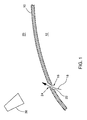
- Figure 1 schematically shows a part 10 cooled by a fluid coolant passing through an interior 12 of the part.
- the fluid coolant may be atmospheric air or another fluid having known thermodynamic properties such as nitrogen. Some of the coolant passes through film-cooling hole 16 along path 18 to an exterior 20 of part 10. Part 10 may have hundreds of such film cooling holes, though only one is shown here for purposes of illustration.
- the temperature at various locations on the interior surface 22 of film-cooling hole 16 near the film-cooling hole exit 24 can be measured using infrared detector 30.
- Infrared detector 30 may be, for example, an imaging infrared radiometer or the like sensitive to electromagnetic radiation of a preselected wavelength. In practice, any wavelength value or range may be used for any material as long as the calibration is done consistently, but one would need to deal with possible issues of signal strength or sensitivity to other factors. If the emissivity is unknown, then an additional step to determine this value must be added.
- Coolant film hole 16 along path 18 generates a large heat transfer coefficient between the coolant and the inside walls 22 of coolant film hole 16, generating a localized cooled zone within coolant film hole 16. Note that this creates a heat sink locally which then conductively removes more heat from surrounding material. It will be understood that these heat transfer effects are described for the case where the part is at a higher temperature than the fluid coolant, and that similar effects will occur when the coolant is at a higher temperature than the part, except that the heat will be transferred into the part instead of out of the part.
- the flow rate through a coolant film hole will induce a total material field thermal response when the fluid is at a different temperature than that of the material.
- this becomes a transient thermal response when, for example, a cooler fluid such as air is flowed through the component and the coolant film holes 16.
- the material defining the coolant film hole 16 is then cooled from the initial temperature of the part 10 to the coolant temperature over a period of time.
- the material thermal transient data, and specifically the surface temperatures solely inside the coolant film hole exits 24, as a function of time, are used herein to deduce the flow rate through each coolant film hole 16.
- the present inventors discovered that accurate, reliable and repeatable detection and measurement of mass flow rates through coolant film holes can be characterized via thermal transient responses associated solely with the surface 22 inside the hole exits 24. More specifically, they discovered that measurement of flow rate through each individual coolant film hole 16 can be determined from only the material temperature response immediately inside a corresponding coolant film hole exit 24, as determined for example, by an infrared device 30, and even when factors such as hole spacing, orientation and shaping are not employed; and that only the simplest possible thermal decay, or thermal buildup response may be required to achieve the desired measurement results.
- an optimized process window is clearly defined by set-point limits on the hole pressure ratio time-response and the internal coolant film hole exit surface temperature-time gradient response.
- FIG 2 is a graph illustrating thermal transient data for a plurality of film-cooling holes (enumerated 16 in Figure 1 ) in which each hole is subjected to an identical pressure ratio condition of 1.5 to generate a plurality of temperature response curves 40.
- Pressure ratio as used herein means the ratio of absolute pressure inside a film-cooling hole 16 as compared to an absolute pressure outside the film-cooling hole 16.
- the temperature response curves 40 may be non-dimensionalized to normalize all response curves 40 to a common basis.
- a comparative technique is employed to determine a film-cooling hole flow rate.
- This comparative technique utilizes a standard test part, sometimes referred to as a "gold standard", that may be configured with a plurality of film-cooling holes and that is first tested by subjecting the standard test part to a series of coolant flow conditions corresponding to different film hole pressure ratios.
- the transient thermal response for a desired film hole is measured at each of the film hole pressure ratios and then is characterized mathematically.
- the resultant mathematical characterizations are then used to generate a calibrated film hole flow rate map (response).
- Figure 2 illustrates a plurality of transient thermal responses 40 associated with a film-cooling hole that is subjected to a film supply pressure 50.
- Film-cooling hole flow rate(s) associated with subsequently manufactured parts are determined as a function of the foregoing mathematically characterized transient thermal responses simply by correlating a measured thermal response characteristic to the calibrated film hole flow rate map using film-cooling hole data from a film-cooling hole in a hole location corresponding to the same hole location as in the standard test part.
- a calibration map according to one aspect is determined empirically.
- numerical predictions such as by computational fluid dynamics and/or finite element analyses could be used in place of or in combination with experimental data to determine the thermal transient response calibration map without experimentation.
- the numerical method would be calibrated with experimental data; but this may require far fewer test points than would be necessary to develop calibration factors derived entirely from experimental data.
- calibration factor is used loosely herein to refer to a relation between the transient thermal response characteristic(s) and film-cooling hole flow rate(s); in which this relation may in fact be a non-linear function.
- the flow rate is determinable from a mathematical characterization of curve 40, e.g. from the relative locations of specific points on curve 40.
- the flow rate through a particular film-cooling hole 16 may be determined, for example, as a function of the magnitude of temperature recovery R, which is the difference that occurs between a first time t 1 and a second time t 2 on curve 40 according to one embodiment.
- the flow rate may be determined, for example, from the length of recovery time or difference in slopes at different points on curve 40.
- the relation between recovery R, recovery time, or difference in slopes and the flow rate through film-cooling hole 16 may be determined empirically, through numerical analysis, or a combination thereof as discussed above.
- the mathematical characterization is an exponential curve having the form Ae - Bt , where the coefficient B correlates to the flow rate.
- This technique for measuring film hole flow rates can be calibrated for film-cooling holes on a test bench, and thus the calibration may be done once for all parts and all uses. Individual film-cooling hole inspection and flow rate measurements can be made.
- a temperature response curve 40 at a particular film-cooling hole 16 pressure ratio is obtained via taking a single snapshot of the internal surface of the film-cooling hole 16 using an infrared camera. The snapshot reveals the temperature at each of several pixel locations that can then be used to construct the corresponding temperature response curve 40 at the selected pressure ratio.
- Figure 3 is a diagram depicting lines of sight 60 viewing of the interior surface(s) 22 of a film-cooling hole 16 from any accessible direction.
- the lines of sight 60 can be from any accessible direction, not only normal to the surface 62 of the part 10.
- Note Figure 3 is two-dimensional, and the actual film-cooling hole 16 is three-dimensional.
- internal surface 22 means any viewable portion of the interior or the film-cooling hole 16, not the external wall surface 62, nor the hidden interior wall 64.
- the viewable surface is that surface nearer the hole exit 24.
- hole exit 24 is actually the imaginary or notional flow exit plane at the surface 62, not a real physical surface. More specifically, hole exit 24 is the flow exit plane as extended from the surrounding part external surface 62 and not any portion of the actual surface 22 inside the hole 16. Thus, although this exit plane cannot be seen in practice, the surface 22 is inside the hole exit 24.
Landscapes
- Engineering & Computer Science (AREA)
- Physics & Mathematics (AREA)
- General Physics & Mathematics (AREA)
- Mechanical Engineering (AREA)
- General Engineering & Computer Science (AREA)
- Fluid Mechanics (AREA)
- Chemical & Material Sciences (AREA)
- Life Sciences & Earth Sciences (AREA)
- Health & Medical Sciences (AREA)
- Analytical Chemistry (AREA)
- Biochemistry (AREA)
- General Health & Medical Sciences (AREA)
- Immunology (AREA)
- Pathology (AREA)
- Investigating Or Analyzing Materials Using Thermal Means (AREA)
- Measuring Volume Flow (AREA)
Abstract
A method for measuring a flow rate through a cooling hole (16) of a film cooled part (10) includes the steps of 1) measuring a transient thermal response of an internal surface temperature corresponding solely to an inside portion (22) of a cooling hole (16) for a film cooled part (10) resulting from a flow of fluid through the part (10), the fluid having an initial temperature that is different from an initial temperature of the film cooled part (10), 2) mathematically characterizing the transient thermal response, and 3) determining the cooling hole flow rate from the mathematical characterization.
Description
- The invention relates generally to film-cooled parts and more particularly to a method for quantifying hole flow rates in film cooled parts.
- Gas turbines and other high-temperature equipment use film cooling extensively for effective protection of the hot gas path components, such as turbine blades. Film cooling refers to a technique for cooling a part in which cool air is discharged through a plurality of small holes in the external walls of the part to provide a thin, cool barrier along the external surface of the part and prevent or reduce direct contact with hot gasses.
- Accurate knowledge of the film hole flow rates is required to determine how each part should behave compared to the design intent. Inspection of parts to measure these flow rates determines the acceptability of the parts for use, and hence, also has a large impact on cost and rework. Such inspection or measurement can be used to help determine the life or remaining life of a part. Inspection of serviced parts determines their ability to be returned to service.
- The standard method for the measurement of film hole flow rates is known as "flow checks". A flow check measures the total flow through a part placed on a test stand. Comparisons to either gauge measurements on good parts and/or analytic models of the flow circuits determines the acceptability. Typically, this process is so time consuming that only overall parts are flow checked, or at best some individual film rows, but never individual film holes. Furthermore, there is no way to distinguish between two parts which may have very different internal thermal performance (heat transfer coefficients), but which flow the same amount and otherwise pass all external dimensional tests.
- One technique that overcomes or alleviates the foregoing disadvantages or drawbacks of the prior art is directed to a method for measuring a flow rate in a cooling hole of a film cooled part comprising measuring a transient thermal response of an external surface temperature of the film cooled part near film cooling holes; mathematically characterizing the transient thermal response; and determining the flow rate from the characterization. Although this technique overcomes or alleviates many of the disadvantages described above, it requires knowledge of hole spacing, orientation and shaping as well as precision in consistently locating the same surface points near holes in each part. It would therefore be advantageous to provide a method for quantifying hole flow rates in film cooled parts without the need for precisely and consistently locating the same surface measurement points near holes in each film cooled part or knowledge of hole spacing, orientation and shaping.
- Briefly, in accordance with one embodiment, a method for measuring a flow rate through a cooling hole of a film cooled part comprises:
- measuring a transient thermal response of an internal surface temperature corresponding solely to an inside portion of a cooling hole for a film cooled part resulting from a flow of fluid through the part, the fluid having an initial temperature that is different from an initial temperature of the film cooled part;
- mathematically characterizing the transient thermal response; and
- determining the cooling hole flow rate from the characterization.
- According to another embodiment, a method for measuring a flow rate through a cooling hole of a film cooled part comprises:
- measuring a transient thermal response of an internal surface temperature corresponding solely to an inside portion of a cooling hole for a film cooled part resulting from a flow of fluid through the part, the fluid having an initial temperature that is different from an initial temperature of the film cooled part;
- mathematically characterizing the transient thermal response; and
- determining a desired thermal response characteristic from the mathematical characterization.
- These and other features, aspects, and advantages of the present invention will become better understood when the following detailed description is read with reference to the accompanying drawings in which like characters represent like parts throughout the drawings, wherein:
-
Figure 1 is a schematic view illustrating a cross section of a portion of a film-cooled part having a film-cooling hole; -
Figure 2 is a graph illustrating thermal transient data for a plurality of film-cooling holes subjected to identical pressure ratio conditions; and -
Figure 3 is a diagram depicting lines of sight viewing of the interior surface(s) of the film-cooling hole depicted inFigure 1 from any accessible direction according to one embodiment. - While the above-identified drawing figures set forth alternative embodiments, other embodiments of the present invention are also contemplated, as noted in the discussion. In all cases, this disclosure presents illustrated embodiments of the present invention by way of representation and not limitation. Numerous other modifications and embodiments can be devised by those skilled in the art which fall within the scope and spirit of the principles of this invention.
-
Figure 1 schematically shows apart 10 cooled by a fluid coolant passing through aninterior 12 of the part. The fluid coolant may be atmospheric air or another fluid having known thermodynamic properties such as nitrogen. Some of the coolant passes through film-cooling hole 16 alongpath 18 to anexterior 20 ofpart 10.Part 10 may have hundreds of such film cooling holes, though only one is shown here for purposes of illustration. - The temperature at various locations on the
interior surface 22 of film-cooling hole 16 near the film-cooling hole exit 24 can be measured usinginfrared detector 30.Infrared detector 30 may be, for example, an imaging infrared radiometer or the like sensitive to electromagnetic radiation of a preselected wavelength. In practice, any wavelength value or range may be used for any material as long as the calibration is done consistently, but one would need to deal with possible issues of signal strength or sensitivity to other factors. If the emissivity is unknown, then an additional step to determine this value must be added. -
Coolant film hole 16 alongpath 18 generates a large heat transfer coefficient between the coolant and theinside walls 22 ofcoolant film hole 16, generating a localized cooled zone withincoolant film hole 16. Note that this creates a heat sink locally which then conductively removes more heat from surrounding material. It will be understood that these heat transfer effects are described for the case where the part is at a higher temperature than the fluid coolant, and that similar effects will occur when the coolant is at a higher temperature than the part, except that the heat will be transferred into the part instead of out of the part. - In practice, the flow rate through a coolant film hole will induce a total material field thermal response when the fluid is at a different temperature than that of the material. In the present methodology embodiments, this becomes a transient thermal response when, for example, a cooler fluid such as air is flowed through the component and the
coolant film holes 16. The material defining thecoolant film hole 16 is then cooled from the initial temperature of thepart 10 to the coolant temperature over a period of time. The material thermal transient data, and specifically the surface temperatures solely inside the coolantfilm hole exits 24, as a function of time, are used herein to deduce the flow rate through eachcoolant film hole 16. - The present inventors discovered that accurate, reliable and repeatable detection and measurement of mass flow rates through coolant film holes can be characterized via thermal transient responses associated solely with the
surface 22 inside thehole exits 24. More specifically, they discovered that measurement of flow rate through each individualcoolant film hole 16 can be determined from only the material temperature response immediately inside a corresponding coolantfilm hole exit 24, as determined for example, by aninfrared device 30, and even when factors such as hole spacing, orientation and shaping are not employed; and that only the simplest possible thermal decay, or thermal buildup response may be required to achieve the desired measurement results. The methodology embodiments described herein advantageously eliminate the need for precision in consistently locating the same surface points near holes in each part when determining film hole flow rates via thermal transient responses, and allows easy detection of measurement (film hole) locations via automation and computer recognition systems. According to one aspect of the invention, an optimized process window is clearly defined by set-point limits on the hole pressure ratio time-response and the internal coolant film hole exit surface temperature-time gradient response. - Note that it is not required to view the same location inside each film hole in a part, nor even precisely the same location inside a common film hole from part-to-part. By use of the interior hole surface, this thermal response is so heavily dominated by the internal heat transfer coefficient that the method is insensitive to such location changes. Recognize that "location" means a single detected point, or a group of detected points, processed to obtain surface temperature.
- The relationship of the coolant film hole flow rate to this thermal transient is of the form:
- Film hole flow rate = f (hole pressure ratio time-response, internal film hole exit surface temperature-time gradient response).
-
Figure 2 is a graph illustrating thermal transient data for a plurality of film-cooling holes (enumerated 16 inFigure 1 ) in which each hole is subjected to an identical pressure ratio condition of 1.5 to generate a plurality oftemperature response curves 40. Pressure ratio as used herein means the ratio of absolute pressure inside a film-cooling hole 16 as compared to an absolute pressure outside the film-cooling hole 16. - If for example, the absolute pressure inside the film-
cooling hole 16 is 20 psi, and the pressure outside the film-cooling hole 16 is 15 psi (or about atmospheric pressure), then the pressure ratio is 20/15 or 1.333. According to one aspect, thetemperature response curves 40 may be non-dimensionalized to normalize allresponse curves 40 to a common basis. - According to one embodiment, a comparative technique is employed to determine a film-cooling hole flow rate. This comparative technique utilizes a standard test part, sometimes referred to as a "gold standard", that may be configured with a plurality of film-cooling holes and that is first tested by subjecting the standard test part to a series of coolant flow conditions corresponding to different film hole pressure ratios. The transient thermal response for a desired film hole is measured at each of the film hole pressure ratios and then is characterized mathematically. The resultant mathematical characterizations are then used to generate a calibrated film hole flow rate map (response).
Figure 2 illustrates a plurality of transientthermal responses 40 associated with a film-cooling hole that is subjected to afilm supply pressure 50. - Film-cooling hole flow rate(s) associated with subsequently manufactured parts are determined as a function of the foregoing mathematically characterized transient thermal responses simply by correlating a measured thermal response characteristic to the calibrated film hole flow rate map using film-cooling hole data from a film-cooling hole in a hole location corresponding to the same hole location as in the standard test part.
- A calibration map according to one aspect is determined empirically. Alternatively, numerical predictions such as by computational fluid dynamics and/or finite element analyses could be used in place of or in combination with experimental data to determine the thermal transient response calibration map without experimentation. In practice, the numerical method would be calibrated with experimental data; but this may require far fewer test points than would be necessary to develop calibration factors derived entirely from experimental data. The term "calibration factor" is used loosely herein to refer to a relation between the transient thermal response characteristic(s) and film-cooling hole flow rate(s); in which this relation may in fact be a non-linear function.
- Once the
transient response curve 40 is obtained for aparticular exit hole 16, the flow rate is determinable from a mathematical characterization ofcurve 40, e.g. from the relative locations of specific points oncurve 40. The flow rate through a particular film-coolinghole 16 may be determined, for example, as a function of the magnitude of temperature recovery R, which is the difference that occurs between a first time t1 and a second time t2 oncurve 40 according to one embodiment. Alternatively, the flow rate may be determined, for example, from the length of recovery time or difference in slopes at different points oncurve 40. The relation between recovery R, recovery time, or difference in slopes and the flow rate through film-coolinghole 16 may be determined empirically, through numerical analysis, or a combination thereof as discussed above. According to one aspect, the mathematical characterization is an exponential curve having the form Ae-Bt , where the coefficient B correlates to the flow rate. - This technique for measuring film hole flow rates can be calibrated for film-cooling holes on a test bench, and thus the calibration may be done once for all parts and all uses. Individual film-cooling hole inspection and flow rate measurements can be made.
- According to one embodiment, a
temperature response curve 40 at a particular film-coolinghole 16 pressure ratio is obtained via taking a single snapshot of the internal surface of the film-coolinghole 16 using an infrared camera. The snapshot reveals the temperature at each of several pixel locations that can then be used to construct the correspondingtemperature response curve 40 at the selected pressure ratio. -
Figure 3 is a diagram depicting lines ofsight 60 viewing of the interior surface(s) 22 of a film-coolinghole 16 from any accessible direction. The lines ofsight 60 can be from any accessible direction, not only normal to thesurface 62 of thepart 10. NoteFigure 3 is two-dimensional, and the actual film-coolinghole 16 is three-dimensional. - With continued reference to
Figure 3 ,internal surface 22 means any viewable portion of the interior or the film-coolinghole 16, not theexternal wall surface 62, nor the hiddeninterior wall 64. In practice, the viewable surface is that surface nearer thehole exit 24. Note that inFigure 3 ,hole exit 24 is actually the imaginary or notional flow exit plane at thesurface 62, not a real physical surface. More specifically,hole exit 24 is the flow exit plane as extended from the surrounding partexternal surface 62 and not any portion of theactual surface 22 inside thehole 16. Thus, although this exit plane cannot be seen in practice, thesurface 22 is inside thehole exit 24. - While only certain features of the invention have been illustrated and described herein, many modifications and changes will occur to those skilled in the art. It is, therefore, to be understood that the appended claims are intended to cover all such modifications and changes as fall within the true spirit of the invention.
- For completeness, various aspects of the invention are now set out in the following numbered clauses:
- 1. A method for measuring a flow rate through a cooling hole of a film cooled part, the method comprising:
- measuring a transient thermal response of an internal surface temperature corresponding solely to an inside portion of a cooling hole for a film cooled part resulting from a flow of fluid through the part, the fluid having an initial temperature that is different from an initial temperature of the film cooled part;
- mathematically characterizing the transient thermal response; and
- determining the cooling hole flow rate from the characterization.
- 2. The method of clause 1, wherein measuring comprises using at least one of mid-infrared detection and longwave infrared detection.
- 3. The method of clause 1 wherein measuring comprises measuring a transient thermal response of a point on an interior surface of the cooling hole near the cooling hole exit.
- 4. The method of clause 1 wherein mathematically characterizing includes fitting an exponential curve to measurements generated from measuring the transient thermal response.
- 5. The method of
clause 4 wherein the exponential curve has the form Ae- Bt, where the coefficient B correlates to the flow rate. - 6. The method of clause 1 wherein said determining comprises applying a calibration factor to the mathematical characterization to obtain the flow rate.
- 7. The method of clause 1 wherein the initial temperature of the fluid is different than the initial temperature of the part.
- 8. The method of clause 1 wherein the fluid is atmospheric air.
- 9. The method of clause 1 wherein measuring comprises:
- commencing the flow of fluid;
- measuring the surface temperature at one or more points within the exit of the cooling hole of the part at or subsequent to pressure stabilization of the flow of fluid and prior to stabilization of the surface temperature.
- 10. The method of clause 9 wherein the characterization comprises a relationship between the measurements of the surface temperature.
- 11. The method of clause 9 wherein the characterization comprises a recovery time, the recovery time being an amount of time that it takes for temperature gradients within the cooling hole to dissipate, wherein the flow rate is determined as a function of the recovery time.
- 12. The method of clause 11, wherein the temperature gradients are determined to be dissipated when a rate of change of the surface temperature reaches a threshold.
- 13. A method for measuring a flow rate through a cooling hole of a film cooled part, the method comprising:
- measuring a transient thermal response of an internal surface temperature corresponding solely to an inside portion of a cooling hole for a film cooled part resulting from a flow of fluid through the part, the fluid having an initial temperature that is different from an initial temperature of the film cooled part;
- mathematically characterizing the transient thermal response; and
- determining a desired thermal response characteristic from the mathematical characterization.
- 14. The method of clause 13, further comprising comparing the desired thermal response characteristic to a corresponding thermal response characteristic associated with a standard film cooled part and determining the flow rate there from.
- 15. The method of clause 13, wherein the desired thermal response characteristic comprises a magnitude of temperature recovery occurring between a first time t1 and a second time t2 based on the mathematical characterization.
- 16. The method of clause 13, wherein the desired thermal response characteristic comprises a difference in slopes at different points based on the mathematical characterization.
- 17. The method of clause 13, wherein the desired thermal response characteristic comprises a length of recovery time based on the mathematical characterization.
- 18. The method of clause 13, further comprising determining the flow rate based on the desired thermal response characteristic using empirical methods.
- 19. The method of clause 13, further comprising determining the flow rate based on the desired thermal response characteristic using a combination of empirical and numerical methods.
- 20. The method of clause 13 wherein mathematically characterizing includes fitting an exponential curve to measurements generated from measuring the transient thermal response.
- 21. The method of
clause 20 wherein the exponential curve has the form Ae-Bt , where the coefficient B correlates to the flow rate.
Claims (10)
- A method for measuring a flow rate through a cooling hole (16) of a film cooled part (10), the method comprising:measuring a transient thermal response of an internal surface temperature corresponding solely to an inside portion (22) of a cooling hole (16) for a film cooled part (10) resulting from a flow of fluid through the part (10), the fluid having an initial temperature that is different from an initial temperature of the film cooled part (10);mathematically characterizing the transient thermal response; anddetermining the cooling hole flow rate from the characterization.
- The method of claim 1, wherein measuring comprises measuring a transient thermal response of a point on an interior surface (22) of the cooling hole (16) near the cooling hole exit (24).
- The method of claim 1 or 2, wherein mathematically characterizing includes fitting an exponential curve to measurements generated from measuring the transient thermal response.
- The method of claim 3, wherein the exponential curve has the form Ae-Bt , where the coefficient B correlates to the flow rate.
- The method of any of the preceding claims, wherein said determining comprises applying a calibration factor to the mathematical characterization to obtain the flow rate.
- The method of any of the preceding claims, wherein measuring comprises:commencing the flow of fluid;measuring the surface temperature at one or more points (22) within the exit (24) of the cooling hole (16) of the part (10) at or subsequent to pressure stabilization of the flow of fluid and prior to stabilization of the surface temperature.
- A method for measuring a flow rate through a cooling hole (16) of a film cooled part (10), the method comprising:measuring a transient thermal response of an internal surface temperature corresponding solely to an inside portion (22) of a cooling hole (16) for a film cooled part (10) resulting from a flow of fluid through the part (10), the fluid having an initial temperature that is different from an initial temperature of the film cooled part (10);mathematically characterizing the transient thermal response; anddetermining a desired thermal response characteristic from the mathematical characterization.
- The method of claim 7, further comprising comparing the desired thermal response characteristic to a corresponding thermal response characteristic associated with a standard film cooled part and determining the flow rate there from.
- The method of claim 7 or 8, wherein mathematically characterizing includes fitting an exponential curve to measurements generated from measuring the transient thermal response.
- The method of claim 9 wherein the exponential curve has the form Ae-Bt , where the coefficient B correlates to the flow rate.
Applications Claiming Priority (1)
| Application Number | Priority Date | Filing Date | Title |
|---|---|---|---|
| US12/413,756 US7890274B2 (en) | 2009-03-30 | 2009-03-30 | Method for quantifying hole flow rates in film cooled parts |
Publications (1)
| Publication Number | Publication Date |
|---|---|
| EP2236997A1 true EP2236997A1 (en) | 2010-10-06 |
Family
ID=42271856
Family Applications (1)
| Application Number | Title | Priority Date | Filing Date |
|---|---|---|---|
| EP10157405A Withdrawn EP2236997A1 (en) | 2009-03-30 | 2010-03-23 | Method for quantifying hole flow rates in film cooled parts |
Country Status (4)
| Country | Link |
|---|---|
| US (1) | US7890274B2 (en) |
| EP (1) | EP2236997A1 (en) |
| JP (1) | JP2010236549A (en) |
| CA (1) | CA2697111A1 (en) |
Cited By (1)
| Publication number | Priority date | Publication date | Assignee | Title |
|---|---|---|---|---|
| EP2466069A1 (en) * | 2010-12-15 | 2012-06-20 | General Electric Company | Thermal inspection and machining systems and methods of use |
Families Citing this family (10)
| Publication number | Priority date | Publication date | Assignee | Title |
|---|---|---|---|---|
| GB0914904D0 (en) * | 2009-08-27 | 2009-09-30 | Rolls Royce Plc | Inspection of holes |
| EP2547995B1 (en) * | 2010-03-17 | 2017-07-05 | Thermal Wave Imaging Inc. | Thermographic detection of internal passageway blockages |
| US9182318B2 (en) | 2013-08-02 | 2015-11-10 | Pratt & Whitney Canada Corp. | Methods and apparatus for inspecting cooling holes |
| US9250188B2 (en) | 2013-09-10 | 2016-02-02 | General Electric Company | System and method for measuring cooling of a component |
| US10048133B2 (en) | 2014-03-07 | 2018-08-14 | United Technologies Corporation | Thermal inspection system |
| US10104313B2 (en) | 2016-07-08 | 2018-10-16 | United Technologies Corporation | Method for turbine component qualification |
| US20180027190A1 (en) * | 2016-07-21 | 2018-01-25 | General Electric Company | Infrared non-destructive evaluation of cooling holes using evaporative membrane |
| US10551327B2 (en) | 2018-04-11 | 2020-02-04 | General Electric Company | Cooling hole inspection system |
| US11885688B2 (en) | 2020-07-21 | 2024-01-30 | General Electric Company | Method and system for inspecting cooling holes of a turbine engine component |
| US11492913B2 (en) | 2020-07-21 | 2022-11-08 | General Electric Company | Cooling hole inspection system |
Citations (4)
| Publication number | Priority date | Publication date | Assignee | Title |
|---|---|---|---|---|
| GB2164746A (en) * | 1984-09-20 | 1986-03-26 | Gen Electric | Cooling hole inspection |
| WO1999054692A2 (en) * | 1998-04-14 | 1999-10-28 | Advanced Fuel Research, Inc. | High speed infrared radiation thermometer, system, and method |
| US20040037344A1 (en) * | 2002-08-23 | 2004-02-26 | Bunker Ronald Scott | Method for quantifying film hole flow rates for film-cooled parts |
| US20080237466A1 (en) * | 2006-06-14 | 2008-10-02 | Meyer Tool, Inc. | Apparatus and Method for Analyzing Relative Outward Flow Characterizations of Fabricated Features |
Family Cites Families (10)
| Publication number | Priority date | Publication date | Assignee | Title |
|---|---|---|---|---|
| US4003A (en) * | 1845-04-16 | Cochrane | ||
| JPS527482B2 (en) * | 1972-05-08 | 1977-03-02 | ||
| US5111046A (en) * | 1991-03-18 | 1992-05-05 | General Electric Company | Apparatus and method for inspecting cooling holes |
| US6422743B1 (en) * | 1999-03-26 | 2002-07-23 | Allison Advanced Development Company | Method for determining heat transfer performance of an internally cooled structure |
| US6585408B2 (en) * | 2001-07-30 | 2003-07-01 | General Electric Company | Method and apparatus for measuring local heat transfer distribution on a surface |
| EP1538439A1 (en) * | 2003-12-01 | 2005-06-08 | Alstom Technology Ltd | Method to determine the internal structure of a heat conducting body |
| US7040805B1 (en) | 2004-05-24 | 2006-05-09 | The United States Of America As Represented By The Secretary Of The Air Force | Method of infrared thermography |
| JP4752841B2 (en) * | 2005-11-01 | 2011-08-17 | 株式会社Ihi | Turbine parts |
| US7388204B2 (en) * | 2005-12-07 | 2008-06-17 | Meyer Tool, Inc. | Apparatus and method for analyzing relative outward flow characterizations of fabricated features |
| US7651261B2 (en) * | 2007-07-10 | 2010-01-26 | General Electric Company | System and method for thermal inspection of parts |
-
2009
- 2009-03-30 US US12/413,756 patent/US7890274B2/en not_active Expired - Fee Related
-
2010
- 2010-03-18 CA CA2697111A patent/CA2697111A1/en not_active Abandoned
- 2010-03-23 EP EP10157405A patent/EP2236997A1/en not_active Withdrawn
- 2010-03-26 JP JP2010071167A patent/JP2010236549A/en active Pending
Patent Citations (4)
| Publication number | Priority date | Publication date | Assignee | Title |
|---|---|---|---|---|
| GB2164746A (en) * | 1984-09-20 | 1986-03-26 | Gen Electric | Cooling hole inspection |
| WO1999054692A2 (en) * | 1998-04-14 | 1999-10-28 | Advanced Fuel Research, Inc. | High speed infrared radiation thermometer, system, and method |
| US20040037344A1 (en) * | 2002-08-23 | 2004-02-26 | Bunker Ronald Scott | Method for quantifying film hole flow rates for film-cooled parts |
| US20080237466A1 (en) * | 2006-06-14 | 2008-10-02 | Meyer Tool, Inc. | Apparatus and Method for Analyzing Relative Outward Flow Characterizations of Fabricated Features |
Non-Patent Citations (1)
| Title |
|---|
| MALDAGUE X ET AL: "Transient thermographic NDE of turbine blades", THERMOSENSE XII. INTERNATIONAL CONFERENCE ON THERMAL SENSING AND IMAGING DIAGNOSTIC APPLICATIONS, ORLANDO, FL, USA, vol. 1313, 18 April 1990 (1990-04-18) - 20 April 1990 (1990-04-20), Proceedings of the SPIE - The International Society for Optical Engineering USA, pages 161 - 171, XP002590530, ISSN: 0277-786X * |
Cited By (1)
| Publication number | Priority date | Publication date | Assignee | Title |
|---|---|---|---|---|
| EP2466069A1 (en) * | 2010-12-15 | 2012-06-20 | General Electric Company | Thermal inspection and machining systems and methods of use |
Also Published As
| Publication number | Publication date |
|---|---|
| JP2010236549A (en) | 2010-10-21 |
| US7890274B2 (en) | 2011-02-15 |
| US20100250155A1 (en) | 2010-09-30 |
| CA2697111A1 (en) | 2010-09-30 |
Similar Documents
| Publication | Publication Date | Title |
|---|---|---|
| US7890274B2 (en) | Method for quantifying hole flow rates in film cooled parts | |
| US6732582B2 (en) | Method for quantifying film hole flow rates for film-cooled parts | |
| US7651261B2 (en) | System and method for thermal inspection of parts | |
| US4916715A (en) | Method and apparatus for measuring the distribution of heat flux and heat transfer coefficients on the surface of a cooled component used in a high temperature environment | |
| US6804622B2 (en) | Method and apparatus for non-destructive thermal inspection | |
| Ochs et al. | A novel calibration method for an infrared thermography system applied to heat transfer experiments | |
| US20090255332A1 (en) | Thermal inspection system and method | |
| Rogers et al. | Effects of double wall cooling configuration and conditions on performance of full coverage effusion cooling | |
| Michalski et al. | Comparison of two surface temperature measurement using thermocouples and infrared camera | |
| Turbeville | Measurements of transition near the corner formed by a highly-swept fin and a cone at Mach 6 | |
| Leontiev et al. | Effect of vortex flows at surface with hollow-type relief on heat transfer coefficients and equilibrium temperature in supersonic flow | |
| Kang et al. | Performance degradation and reliability analysis of a MEMS flow sensor with accelerated degradation testing | |
| Waidmann et al. | Application of thermochromic liquid crystal mixtures for transient heat transfer measurements | |
| Chrzanowski et al. | Testing and evaluation of thermal cameras for absolute temperature measurement | |
| Poser et al. | Liquid crystal thermography for transient heat transfer measurements in complex internal cooling systems | |
| Brack et al. | A comparison between transient heat transfer measurements using TLC and IR thermography | |
| Pantou et al. | Identification of critical stress location on PCBs taking into account the influence of fixations and housing | |
| Hu et al. | Infrared Radiation Transparent Film Impact on Thermal Measurement | |
| Dvoynishnikov et al. | Optoelectronic Differential Cloudy Triangulation Method for Measuring Geometry of Hot Moving Objects | |
| Wagner et al. | The transient liquid crystal technique: influence of surface curvature and finite wall thickness | |
| El-Sharkawy et al. | Estimates of the Convective Heat-Transfer Coefficients for Under-Hood and Under-Body Components | |
| Bunker et al. | The determination of in-situ film hole flow rates using a transient thermal inertia method | |
| JP2006125933A (en) | Film inspection method film inspection device and film inspection system | |
| Nirmalan et al. | The Measurement of Full-Surface Internal Heat Transfer Coefficients for Turbine Airfoils Using a Non-Destructive Thermal Inertia Technique | |
| Andonova et al. | Application of IRT NDT for ensuring heat robustness of LED Modules |
Legal Events
| Date | Code | Title | Description |
|---|---|---|---|
| PUAI | Public reference made under article 153(3) epc to a published international application that has entered the european phase |
Free format text: ORIGINAL CODE: 0009012 |
|
| AK | Designated contracting states |
Kind code of ref document: A1 Designated state(s): AT BE BG CH CY CZ DE DK EE ES FI FR GB GR HR HU IE IS IT LI LT LU LV MC MK MT NL NO PL PT RO SE SI SK SM TR |
|
| AX | Request for extension of the european patent |
Extension state: AL BA ME RS |
|
| 17P | Request for examination filed |
Effective date: 20110406 |
|
| STAA | Information on the status of an ep patent application or granted ep patent |
Free format text: STATUS: THE APPLICATION IS DEEMED TO BE WITHDRAWN |
|
| 18D | Application deemed to be withdrawn |
Effective date: 20151001 |