EP2236991A2 - Sensor assembly and fixing method thereof - Google Patents
Sensor assembly and fixing method thereof Download PDFInfo
- Publication number
- EP2236991A2 EP2236991A2 EP10001624A EP10001624A EP2236991A2 EP 2236991 A2 EP2236991 A2 EP 2236991A2 EP 10001624 A EP10001624 A EP 10001624A EP 10001624 A EP10001624 A EP 10001624A EP 2236991 A2 EP2236991 A2 EP 2236991A2
- Authority
- EP
- European Patent Office
- Prior art keywords
- bracket
- spacer
- rotation sensor
- sensor
- fixing
- Prior art date
- Legal status (The legal status is an assumption and is not a legal conclusion. Google has not performed a legal analysis and makes no representation as to the accuracy of the status listed.)
- Withdrawn
Links
Images


Classifications
-
- F—MECHANICAL ENGINEERING; LIGHTING; HEATING; WEAPONS; BLASTING
- F16—ENGINEERING ELEMENTS AND UNITS; GENERAL MEASURES FOR PRODUCING AND MAINTAINING EFFECTIVE FUNCTIONING OF MACHINES OR INSTALLATIONS; THERMAL INSULATION IN GENERAL
- F16H—GEARING
- F16H57/00—General details of gearing
- F16H57/02—Gearboxes; Mounting gearing therein
-
- G—PHYSICS
- G01—MEASURING; TESTING
- G01D—MEASURING NOT SPECIALLY ADAPTED FOR A SPECIFIC VARIABLE; ARRANGEMENTS FOR MEASURING TWO OR MORE VARIABLES NOT COVERED IN A SINGLE OTHER SUBCLASS; TARIFF METERING APPARATUS; MEASURING OR TESTING NOT OTHERWISE PROVIDED FOR
- G01D11/00—Component parts of measuring arrangements not specially adapted for a specific variable
- G01D11/24—Housings ; Casings for instruments
- G01D11/245—Housings for sensors
-
- G—PHYSICS
- G01—MEASURING; TESTING
- G01D—MEASURING NOT SPECIALLY ADAPTED FOR A SPECIFIC VARIABLE; ARRANGEMENTS FOR MEASURING TWO OR MORE VARIABLES NOT COVERED IN A SINGLE OTHER SUBCLASS; TARIFF METERING APPARATUS; MEASURING OR TESTING NOT OTHERWISE PROVIDED FOR
- G01D11/00—Component parts of measuring arrangements not specially adapted for a specific variable
- G01D11/30—Supports specially adapted for an instrument; Supports specially adapted for a set of instruments
-
- G—PHYSICS
- G01—MEASURING; TESTING
- G01P—MEASURING LINEAR OR ANGULAR SPEED, ACCELERATION, DECELERATION, OR SHOCK; INDICATING PRESENCE, ABSENCE, OR DIRECTION, OF MOVEMENT
- G01P1/00—Details of instruments
- G01P1/04—Special adaptations of driving means
Definitions
- This invention relates to a sensor assembly.
- a rotation sensor that detects a rotation speed of a rotational element in an automatic transmission in order to control the automatic transmission is attached via a bracket to a control valve provided on a case lower portion of the automatic transmission. More specifically, an oil pressure sensor and an oil temperature sensor are attached to the bracket together with the rotation sensor to form a sub-assembly, whereupon the sub-assembly is fastened to the control valve by a bolt.
- the rotation sensor cannot be fixed precisely in a position where the rotation speed of the detection subject can be detected accurately. More specifically, a clearance for assembly purposes is required between the bolt and a bolt hole of the bracket, and the positional precision of the rotation sensor deteriorates in accordance with this clearance. Furthermore, when the bracket is formed simply by pressing a metal plate, it is difficult to improve the shape precision of the bracket, and in order to improve the shape precision of the bracket, the bracket must be subjected to cutting processing and the like, leading to an increase in cost. Moreover, if the bracket is deformed by a tightening force of the bolt, the rotation sensor cannot be fixed precisely in a position where the rotation speed of the detection subject can be detected accurately.
- An object of this invention is to provide a sensor assembly with which cost increases can be suppressed and a rotation sensor can detect a rotation speed accurately even if a bracket deforms.
- a sensor assembly includes a rotation sensor, a bracket that is fixed to a fixing subject member while holding the rotation sensor, and a spacer that is attached to the bracket and contacts the rotation sensor and the fixing subject member.
- the rotation sensor is held by the bracket while sandwiched between the spacer and the bracket.
- a method of fixing a sensor assembly to a fixing subject member includes preparing a bracket that is fixed to a fixing subject member, holding a rotation sensor to the bracket by sandwiched between the spacer and the bracket, and fixing the bracket that holds the rotation sensor and the spacer to the fixing subject member as the spacer contacts to the fixing subject member.
- the spacer is interposed between the rotation sensor and the fixing subject member and the rotation sensor is positioned relative to the fixing subject member by the spacer.
- FIG. 1 is a schematic diagram showing an automatic transmission to which a sensor assembly according to an embodiment is applied.
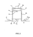
- FIG. 2 is an enlarged view of a sensor attachment portion.
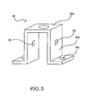
- FIG. 3 is a detailed view of a bracket.
- FIG. 4 is a detailed view of a spacer.
- FIG. 1 is a schematic diagram showing a part of an automatic transmission 1 for a vehicle to which a sensor assembly according to an embodiment of this invention is applied.
- a torque converter 2 is connected to a drive plate, which is fixed to a crankshaft end portion of an engine, by a bolt or the like, and includes a pump impeller 2a that is driven to rotate directly by the crankshaft and a turbine runner 2b that is driven to rotate by the pump impeller 2a via a fluid.
- a clutch mechanism 3 includes a clutch drum 4 fixed to an input shaft 6, which is connected to the turbine runner 2b, by a bolt or the like, a plurality of driven plates 8, respective outer peripheral portions of which engage with an inner peripheral portion of the clutch drum 4, drive plates 9 arranged alternately with the driven plates 8, a clutch hub 5, an outer peripheral portion of which engages with respective inner peripheral portions of the drive plates 9, and an intermediate shaft 7 connected to the clutch hub 5.
- a control valve 10 is attached to a lower surface opening portion of the automatic transmission 1, and a rotation sensor 11 for detecting a rotation speed of the clutch drum 4 is disposed on an upper surface of the control valve 10.
- FIG. 2 is an enlarged view of an attachment part of the rotation sensor 11 shown in FIG. 1
- FIGs. 3 and 4 are views respectively illustrating a bracket 20 and a spacer 21 to be described below.
- the rotation sensor 11 takes a stepped cylindrical shape including a detection portion 11b and a body part 11c having a larger diameter than the detection portion 11b.
- a cylindrical sensor projecting portion 11a is provided on a lower surface of the body part 11c.
- the bracket 20 takes a doorway shape comprising an upper surface 20a having a hole that is penetrated by the detection portion 11b of the rotation sensor 11, two side faces 20b that extend from the upper surface 20a in the direction of the control valve 10, and an attachment surface 20c that extends parallel to an upper surface of the control valve 10 from a lower end of each side face 20b.
- a hole (to be referred to as a lock portion hereafter) 30 is provided in each side face 20b.
- the spacer 21 is a resin rectangular parallelepiped in which a spacer recessed portion 21b into which the projecting portion 11a provided on the lower surface of the rotation sensor 11 fits is provided in an upper surface and a cylindrical spacer projecting portion 21a that fits into a recessed portion 10a provided in the control valve 10 is provided on a lower surface.
- a projecting portion (to be referred to as a spacer lock portion hereafter) 40 that engages with the lock portion 30 is provided on surfaces that oppose the respective side faces 20b of the bracket 20.
- the spacer lock portion 40 may be molded integrally with the spacer member or attached to the side faces of the spacer 20 as a separate member.
- the spacer lock portion 40 that projects from the side face of the spacer 21 is engaged with the lock portion 30 upon elastic deformation of the side face 20b of the bracket 20. The positions in which the lock portion 30 and spacer lock portion 40 are provided will be described below.
- the spacer 21 is disposed on the upper surface of the control valve 10 such that the spacer projecting portion 21a fits into the C/V recessed portion 10a
- the rotation sensor 11 is disposed thereabove such that the sensor projecting portion 11a fits into the spacer recessed portion 21b
- the bracket 20 is placed over the rotation sensor 11 and the spacer 21 such that the detection portion 11b of the rotation sensor 11 penetrates the hole in the upper surface 20a of the bracket 20.
- the attachment surface 20c of the bracket 20 is then fastened to the upper surface of the control valve 10 by bolts 22 such that the rotation sensor 11 is fixed to the control valve 10 while being pressed from an upper side by the bracket 20.
- the spacer lock portion 40 is engaged with the lock portion 30, whereby the spacer 21 is fixed to the bracket 20 and the body part 11c of the rotation sensor 11 is sandwiched between the upper surface 20a of the bracket 20 and the upper surface of the spacer 21.
- the bracket 20, the rotation sensor 11, and the spacer 21, which together constitute a sensor assembly can be formed into a so-called sub-assembly without the need for a separate member to prevent the rotation sensor 11 from falling out of the bracket 20, and as a result, an assembly process of the automatic transmission 1 can be simplified.
- the rotation sensor 11 is positioned relative to the spacer 21 by the sensor projecting portion 11a and the spacer recessed portion 21b, while the spacer 21 is positioned relative to the upper surface of the control valve 10 by the spacer projecting portion 21a and the C/V recessed portion 10a.
- play (or looseness)between a side face of the cylindrical spacer projecting portion 21a and an inner peripheral surface of the C/V recessed portion 10a is set to be smaller than play between the spacer lock portion 40 and the lock portion 30.
- play between a side face of the cylindrical sensor projecting portion 11a and an inner peripheral surface of the spacer recessed portion 21b is set to be smaller than play between a side face of the detection portion 11b of the sensor 11 and an inner peripheral surface of the hole in the upper surface 20a of the bracket 20.
- the rotation sensor 11 is positioned by the spacer 21, and therefore the bracket 20 does not have to be subjected to cutting processing and the like in order to improve the shape precision of the bracket 20, for example, with the result that cost increases can be suppressed and positional precision can be secured in the rotation sensor. Moreover, even if the bracket 20 deforms when the bolt 22 is tightened, variation in the position of the rotation sensor 11 accompanying this deformation can be suppressed.
- the spacer projecting portion 21a is inserted into the C/V recessed portion 10a, but the invention is not limited to this constitution, and any constitution that allows the spacer 21 to be positioned relative to the control valve 10, for example a constitution in which a recessed portion is provided in the spacer 21 and a projecting portion provided on the control valve 10 is fitted into the recessed portion, a constitution in which recessed portions are provided in both components and a single positioning pin is fitted into the two recessed portions, and so on, may be employed. This applies likewise to positioning of the rotation sensor 11 relative to the spacer 21.
- the spacer lock portion 40 is engaged with the lock portion 30 was described as a structure for attaching the spacer 21 to the bracket 20, but the invention is not limited to this constitution, and any constitution that prevents the spacer 21 from falling out of the bracket 20 when the sensor assembly is formed into a sub-assembly may be employed.
- the spacer 21 is formed from resin but is not limited thereto.
Landscapes
- Physics & Mathematics (AREA)
- General Physics & Mathematics (AREA)
- Engineering & Computer Science (AREA)
- General Engineering & Computer Science (AREA)
- Mechanical Engineering (AREA)
- Control Of Transmission Device (AREA)
- General Details Of Gearings (AREA)
- Transmission And Conversion Of Sensor Element Output (AREA)
Abstract
Description
- This invention relates to a sensor assembly.
- Upon use, a sensor must be fixed in a position where it can detect a detection subject accurately. Therefore, in
JP2001-271918A - However, with the sensor attachment method described in the above document, the rotation sensor cannot be fixed precisely in a position where the rotation speed of the detection subject can be detected accurately. More specifically, a clearance for assembly purposes is required between the bolt and a bolt hole of the bracket, and the positional precision of the rotation sensor deteriorates in accordance with this clearance. Furthermore, when the bracket is formed simply by pressing a metal plate, it is difficult to improve the shape precision of the bracket, and in order to improve the shape precision of the bracket, the bracket must be subjected to cutting processing and the like, leading to an increase in cost. Moreover, if the bracket is deformed by a tightening force of the bolt, the rotation sensor cannot be fixed precisely in a position where the rotation speed of the detection subject can be detected accurately.
- An object of this invention is to provide a sensor assembly with which cost increases can be suppressed and a rotation sensor can detect a rotation speed accurately even if a bracket deforms.
- According to an aspect of the present invention, a sensor assembly is provided. The sensor includes a rotation sensor, a bracket that is fixed to a fixing subject member while holding the rotation sensor, and a spacer that is attached to the bracket and contacts the rotation sensor and the fixing subject member.
- The rotation sensor is held by the bracket while sandwiched between the spacer and the bracket.
- According to another aspect of the invention, a method of fixing a sensor assembly to a fixing subject member is provided. The method includes preparing a bracket that is fixed to a fixing subject member, holding a rotation sensor to the bracket by sandwiched between the spacer and the bracket, and fixing the bracket that holds the rotation sensor and the spacer to the fixing subject member as the spacer contacts to the fixing subject member.
- According to these aspects described above, the spacer is interposed between the rotation sensor and the fixing subject member and the rotation sensor is positioned relative to the fixing subject member by the spacer. As a result, cost increases can be suppressed and positional precision can be secured in the rotation sensor even if the bracket deforms when a bolt is tightened.
- Embodiments and advantages of this invention will be described in detail below with reference to the attached figures.
-
FIG. 1 is a schematic diagram showing an automatic transmission to which a sensor assembly according to an embodiment is applied. -
FIG. 2 is an enlarged view of a sensor attachment portion. -
FIG. 3 is a detailed view of a bracket. -
FIG. 4 is a detailed view of a spacer. -
FIG. 1 is a schematic diagram showing a part of an automatic transmission 1 for a vehicle to which a sensor assembly according to an embodiment of this invention is applied. - A
torque converter 2 is connected to a drive plate, which is fixed to a crankshaft end portion of an engine, by a bolt or the like, and includes a pump impeller 2a that is driven to rotate directly by the crankshaft and a turbine runner 2b that is driven to rotate by the pump impeller 2a via a fluid. - A clutch mechanism 3 includes a
clutch drum 4 fixed to aninput shaft 6, which is connected to the turbine runner 2b, by a bolt or the like, a plurality of drivenplates 8, respective outer peripheral portions of which engage with an inner peripheral portion of theclutch drum 4,drive plates 9 arranged alternately with the drivenplates 8, aclutch hub 5, an outer peripheral portion of which engages with respective inner peripheral portions of thedrive plates 9, and anintermediate shaft 7 connected to theclutch hub 5. - A
control valve 10 is attached to a lower surface opening portion of the automatic transmission 1, and arotation sensor 11 for detecting a rotation speed of theclutch drum 4 is disposed on an upper surface of thecontrol valve 10. -
FIG. 2 is an enlarged view of an attachment part of therotation sensor 11 shown inFIG. 1 , andFIGs. 3 and4 are views respectively illustrating abracket 20 and aspacer 21 to be described below. - The
rotation sensor 11 takes a stepped cylindrical shape including adetection portion 11b and abody part 11c having a larger diameter than thedetection portion 11b. A cylindricalsensor projecting portion 11a is provided on a lower surface of thebody part 11c. - The
bracket 20 takes a doorway shape comprising anupper surface 20a having a hole that is penetrated by thedetection portion 11b of therotation sensor 11, two side faces 20b that extend from theupper surface 20a in the direction of thecontrol valve 10, and anattachment surface 20c that extends parallel to an upper surface of thecontrol valve 10 from a lower end of eachside face 20b. A hole (to be referred to as a lock portion hereafter) 30 is provided in eachside face 20b. - The
spacer 21 is a resin rectangular parallelepiped in which a spacer recessedportion 21b into which the projectingportion 11a provided on the lower surface of therotation sensor 11 fits is provided in an upper surface and a cylindricalspacer projecting portion 21a that fits into arecessed portion 10a provided in thecontrol valve 10 is provided on a lower surface. A projecting portion (to be referred to as a spacer lock portion hereafter) 40 that engages with thelock portion 30 is provided on surfaces that oppose therespective side faces 20b of thebracket 20. - The
spacer lock portion 40 may be molded integrally with the spacer member or attached to the side faces of thespacer 20 as a separate member. Thespacer lock portion 40 that projects from the side face of thespacer 21 is engaged with thelock portion 30 upon elastic deformation of theside face 20b of thebracket 20. The positions in which thelock portion 30 andspacer lock portion 40 are provided will be described below. - These constitutional components are attached to the
control valve 10 in the manner shown inFIG. 2 by the step of fitting therotation sensor 11 to thespacer 21, and the step of engaging therotation sensor 11 and thespacer 21 with thebracket 20. More specifically, thespacer 21 is disposed on the upper surface of thecontrol valve 10 such that thespacer projecting portion 21a fits into the C/V recessedportion 10a, therotation sensor 11 is disposed thereabove such that thesensor projecting portion 11a fits into the spacer recessedportion 21b, and thebracket 20 is placed over therotation sensor 11 and thespacer 21 such that thedetection portion 11b of therotation sensor 11 penetrates the hole in theupper surface 20a of thebracket 20. Theattachment surface 20c of thebracket 20 is then fastened to the upper surface of thecontrol valve 10 bybolts 22 such that therotation sensor 11 is fixed to thecontrol valve 10 while being pressed from an upper side by thebracket 20. - The
spacer lock portion 40 is engaged with thelock portion 30, whereby thespacer 21 is fixed to thebracket 20 and thebody part 11c of therotation sensor 11 is sandwiched between theupper surface 20a of thebracket 20 and the upper surface of thespacer 21. Hence, thebracket 20, therotation sensor 11, and thespacer 21, which together constitute a sensor assembly, can be formed into a so-called sub-assembly without the need for a separate member to prevent therotation sensor 11 from falling out of thebracket 20, and as a result, an assembly process of the automatic transmission 1 can be simplified. - As described above, the
rotation sensor 11 is positioned relative to thespacer 21 by thesensor projecting portion 11a and the spacer recessedportion 21b, while thespacer 21 is positioned relative to the upper surface of thecontrol valve 10 by thespacer projecting portion 21a and the C/V recessedportion 10a. - Further, play (or looseness)between a side face of the cylindrical
spacer projecting portion 21a and an inner peripheral surface of the C/V recessedportion 10a is set to be smaller than play between thespacer lock portion 40 and thelock portion 30. Hence, even when a dimension error occurs in thebracket 20, positional deviation of thespacer 21 relative to thecontrol valve 10 is limited by the dimensions of thespacer projecting portion 21a and the C/V recessedportion 10a, and therefore positional deviation of therotation sensor 11 relative to thecontrol valve 10 can be suppressed. - Moreover, play between a side face of the cylindrical
sensor projecting portion 11a and an inner peripheral surface of the spacer recessedportion 21b is set to be smaller than play between a side face of thedetection portion 11b of thesensor 11 and an inner peripheral surface of the hole in theupper surface 20a of thebracket 20. Hence, even when a dimension error occurs in thebracket 20, positional deviation of therotation sensor 11 relative to thespacer 21 is limited by the dimensions of thesensor projecting portion 11a and the spacer recessedportion 21b, and therefore positional deviation of therotation sensor 11 relative to thespacer 21 can be suppressed. - In other words, the
rotation sensor 11 is positioned by thespacer 21, and therefore thebracket 20 does not have to be subjected to cutting processing and the like in order to improve the shape precision of thebracket 20, for example, with the result that cost increases can be suppressed and positional precision can be secured in the rotation sensor. Moreover, even if thebracket 20 deforms when thebolt 22 is tightened, variation in the position of therotation sensor 11 accompanying this deformation can be suppressed. - It should be noted that in the above embodiment, the
spacer projecting portion 21a is inserted into the C/V recessedportion 10a, but the invention is not limited to this constitution, and any constitution that allows thespacer 21 to be positioned relative to thecontrol valve 10, for example a constitution in which a recessed portion is provided in thespacer 21 and a projecting portion provided on thecontrol valve 10 is fitted into the recessed portion, a constitution in which recessed portions are provided in both components and a single positioning pin is fitted into the two recessed portions, and so on, may be employed. This applies likewise to positioning of therotation sensor 11 relative to thespacer 21. - Further, a constitution in which the
spacer lock portion 40 is engaged with thelock portion 30 was described as a structure for attaching thespacer 21 to thebracket 20, but the invention is not limited to this constitution, and any constitution that prevents thespacer 21 from falling out of thebracket 20 when the sensor assembly is formed into a sub-assembly may be employed. Moreover, thespacer 21 is formed from resin but is not limited thereto. - Furthermore, in this embodiment, a constitution in which the
rotation sensor 11 that detects the rotation speed of theclutch drum 4 is attached to the upper surface of thecontrol valve 10 disposed in a main body lower portion of the automatic transmission 1 was described, but the invention is not limited to this constitution and may be applied similarly to any constitution in which a rotation sensor is fixed to another component. - The following effects are obtained from the embodiment described above.
- (1) The
rotation sensor 11, thebracket 20 that is fixed to the control valve (a fixing subject member) 10 while holding therotation sensor 11, and thespacer 21 that is attached to thebracket 20 and contacts both therotation sensor 11 and thecontrol valve 10 in a state where thebracket 20 is fixed to thecontrol valve 10 are provided, and therotation sensor 11 is held by thebracket 20 while sandwiched between thespacer 21 attached to thebracket 20 and thebracket 20. As a result, cost increases can be suppressed and positional precision can be secured in therotation sensor 11 even if thebracket 20 deforms when being fixed to thecontrol valve 10. - (2) The play between the side face of the spacer projecting portion (a fitting portion provided on the spacer 21) 21a and the inner peripheral surface of the C/V recessed portion (a fitting subject portion provided in the fixing subject member) 10a is smaller than the play between the
lock portion 30 and thespacer lock portion 40, and therefore positional deviation of therotation sensor 11 relative to thecontrol valve 10 can be suppressed even when a dimension error occurs in thebracket 20. - (3) The play between the side face of the sensor projecting portion (a fitting portion provided on the sensor) 11a and the inner peripheral surface of the spacer recessed portion (a fitting subject portion provided in the spacer) 21b is smaller than the play between the side face of the
detection portion 11b of therotation sensor 11 and the inner peripheral surface of the hole in theupper surface 20a of thebracket 20, and therefore positional deviation of therotation sensor 11 relative to thespacer 21 can be suppressed. It should be noted that the above embodiment describes a structure in which a hole penetrated by thedetection portion 11b of the rotation sensor is provided in theupper surface 20a of thebracket 20, but the invention is not limited to this structure, and a cutout penetrated by thedetection portion 11b of the rotation sensor may be provided in theupper surface 20a of thebracket 20 instead. - Further, this invention is not limited to the embodiment described above, and may of course be subjected to various modifications within the scope of the technical spirit of the claims.
- This application claims priority based on Japanese Patent Application No.
2009-84847
Claims (4)
- A sensor assembly comprising:a rotation sensor (11);a bracket (20) that is fixed to the fixing subject member (10) while holding the rotation sensor (11); anda spacer (21) that is attached to the bracket (20) and contacts the rotation sensor (11) and the fixing subject member (10),wherein the rotation sensor (11) is held by the bracket (20) while sandwiched between the spacer (21) and the bracket (20).
- The sensor assembly as defined in Claim 1, wherein the spacer (21) comprises a fitting portion (21a) that is fitted into a fitting subject portion (10a) provided in the fixing subject member (10),
the spacer (21) comprises an engagement portion (40) that engages with an engagement subject portion (30) provided in the bracket (20), and
a play between the fitting portion (21 a) of the spacer (21) and the fitting subject portion (10a) of the fixing subject member (10) is smaller than a play between the engagement portion (40) of the spacer (21) and the engagement subject portion (30) of the bracket (20). - The sensor assembly as defined in Claim 1 or Claim 2, wherein the rotation sensor (11) comprises a fitting portion (11a) that is fitted into a fitting subject portion (21b) provided in the spacer (21),
the bracket (20) comprises a through hole penetrated by a part of the rotation sensor (11), and
a play between the fitting portion (11a) of the rotation sensor (11) and the fitting subject portion (21b) of the spacer (21) is smaller than a play between
the rotation sensor (11) and the through hole in the bracket (20). - A method of fixing a sensor assembly to a fixing subject member comprising :preparing a bracket (20) that is fixed to the fixing subject member (10);holding a rotation sensor (11) to the bracket (20) by sandwiching the rotation sensor between a spacer (21) and the bracket (20); andfixing the bracket (20) that holds the rotation sensor (11) and the spacer (21) to the fixing subject member (10) so that the spacer (21) contacts the fixing subject member (10).
Applications Claiming Priority (1)
| Application Number | Priority Date | Filing Date | Title |
|---|---|---|---|
| JP2009084847A JP5039741B2 (en) | 2009-03-31 | 2009-03-31 | Sensor assembly |
Publications (2)
| Publication Number | Publication Date |
|---|---|
| EP2236991A2 true EP2236991A2 (en) | 2010-10-06 |
| EP2236991A3 EP2236991A3 (en) | 2017-01-04 |
Family
ID=42352228
Family Applications (1)
| Application Number | Title | Priority Date | Filing Date |
|---|---|---|---|
| EP10001624.5A Withdrawn EP2236991A3 (en) | 2009-03-31 | 2010-02-17 | Sensor assembly and fixing method thereof |
Country Status (5)
| Country | Link |
|---|---|
| US (1) | US8505866B2 (en) |
| EP (1) | EP2236991A3 (en) |
| JP (1) | JP5039741B2 (en) |
| KR (1) | KR101697638B1 (en) |
| CN (1) | CN101852230B (en) |
Families Citing this family (6)
| Publication number | Priority date | Publication date | Assignee | Title |
|---|---|---|---|---|
| CN102788237B (en) * | 2012-08-14 | 2014-01-15 | 中国水电顾问集团中南勘测设计研究院 | Sleeve-type liftable universal base |
| DE102015219005A1 (en) * | 2015-10-01 | 2017-04-06 | Robert Bosch Gmbh | Electronic module, in particular for transmission control, with sensor connection by means of flexible conductor foil positioned via centering pins |
| FR3047801B1 (en) * | 2016-02-12 | 2018-02-16 | Continental Automotive France | METHOD FOR FORMING AN IMPERDABLE SPACER LOCATED IN AN ACCELEROMETER SENSOR BASE AND SENSOR PROVIDED WITH SUCH A BASE |
| JP6437036B2 (en) | 2017-03-30 | 2018-12-12 | 本田技研工業株式会社 | Actuator setting method and fluid pressure control circuit |
| JP6992435B2 (en) * | 2017-11-22 | 2022-01-13 | スズキ株式会社 | Crank angle sensor mounting structure |
| CN108730699A (en) * | 2018-04-29 | 2018-11-02 | 东莞市联洲知识产权运营管理有限公司 | Sensor mounting bracket on intelligent medicine storage cabinet of nurse station |
Citations (2)
| Publication number | Priority date | Publication date | Assignee | Title |
|---|---|---|---|---|
| JP2001271918A (en) | 2000-03-27 | 2001-10-05 | Unisia Jecs Corp | Drive for automatic transmission |
| JP2009084847A (en) | 2007-09-28 | 2009-04-23 | Sanwa Shutter Corp | Locking device |
Family Cites Families (8)
| Publication number | Priority date | Publication date | Assignee | Title |
|---|---|---|---|---|
| US4090099A (en) * | 1976-03-31 | 1978-05-16 | Wagner Electric Corporation | Point sensor mounting apparatus |
| GB9122146D0 (en) * | 1991-10-18 | 1991-11-27 | Gullick Dobson Ltd | Mine roof supports |
| DE9418469U1 (en) * | 1994-11-18 | 1995-01-12 | Skf Gmbh, 97421 Schweinfurt | Speed detection arrangement with a rod-shaped sensor |
| JP3394835B2 (en) * | 1995-03-20 | 2003-04-07 | 株式会社キャットアイ | Parts mounting device |
| JP2002168658A (en) * | 2000-11-29 | 2002-06-14 | Fuji Electric Co Ltd | Absolute value encoder and its design value determination method |
| JP2002303635A (en) * | 2001-01-30 | 2002-10-18 | Sumitomo Electric Ind Ltd | Rotation detection sensor |
| JP4247721B2 (en) * | 2006-11-17 | 2009-04-02 | いすゞ自動車株式会社 | Wheel rotation sensor mounting structure |
| MX2010009035A (en) * | 2008-02-18 | 2011-03-04 | Stemco Lp | Apparatus for isolating a sensor from vibration. |
-
2009
- 2009-03-31 JP JP2009084847A patent/JP5039741B2/en active Active
-
2010
- 2010-02-17 EP EP10001624.5A patent/EP2236991A3/en not_active Withdrawn
- 2010-03-09 US US12/720,464 patent/US8505866B2/en active Active
- 2010-03-26 KR KR1020100027042A patent/KR101697638B1/en not_active Expired - Fee Related
- 2010-03-26 CN CN201010145629.7A patent/CN101852230B/en active Active
Patent Citations (2)
| Publication number | Priority date | Publication date | Assignee | Title |
|---|---|---|---|---|
| JP2001271918A (en) | 2000-03-27 | 2001-10-05 | Unisia Jecs Corp | Drive for automatic transmission |
| JP2009084847A (en) | 2007-09-28 | 2009-04-23 | Sanwa Shutter Corp | Locking device |
Also Published As
| Publication number | Publication date |
|---|---|
| CN101852230A (en) | 2010-10-06 |
| US20100243842A1 (en) | 2010-09-30 |
| CN101852230B (en) | 2014-07-23 |
| KR101697638B1 (en) | 2017-01-18 |
| JP5039741B2 (en) | 2012-10-03 |
| US8505866B2 (en) | 2013-08-13 |
| KR20100109422A (en) | 2010-10-08 |
| EP2236991A3 (en) | 2017-01-04 |
| JP2010236606A (en) | 2010-10-21 |
Similar Documents
| Publication | Publication Date | Title |
|---|---|---|
| US8505866B2 (en) | Sensor assembly and fixing method thereof | |
| CN106870588B (en) | Clutch device for motorcycle | |
| CN106838040B (en) | Clutch device for motorcycle | |
| US10808825B2 (en) | Bearing system and gear unit | |
| EP1602854B1 (en) | Torque fluctuation absorbing apparatus having structure for reducing misalignment of torque limiter during asembling thereof | |
| JP5118550B2 (en) | Roller type one-way clutch for motorcycle starters | |
| US7757570B1 (en) | Torque sensor with alignment system | |
| EP2034203B1 (en) | Assembly error prevention member and universal joint having same member | |
| US8647211B2 (en) | Torque limiter | |
| EP2722558A1 (en) | Power transmission device and compressor equipped with power transmission device | |
| US9415799B2 (en) | Power steering device | |
| EP2059689B1 (en) | Flexplate coupling for a wet clutch transmission | |
| CN113494543A (en) | Clutch device | |
| JP5574101B2 (en) | Gear damper | |
| EP3869069B1 (en) | Lock-up apparatus for torque converter | |
| JP6568336B2 (en) | Backlash adjustment method | |
| JP2011027122A (en) | Torque limiter device | |
| US9765747B2 (en) | Starter return mechanism | |
| US11274711B2 (en) | Clutch device | |
| US6609601B2 (en) | Friction clutch | |
| US20130160735A1 (en) | Throttle position sensor assembly | |
| JP5525435B2 (en) | Shaft coupling with torque limiter | |
| US11466765B2 (en) | Lock-up device of torque converter | |
| JP2007255432A (en) | Torsional damper | |
| JP5081060B2 (en) | Power transmission device |
Legal Events
| Date | Code | Title | Description |
|---|---|---|---|
| PUAI | Public reference made under article 153(3) epc to a published international application that has entered the european phase |
Free format text: ORIGINAL CODE: 0009012 |
|
| AK | Designated contracting states |
Kind code of ref document: A2 Designated state(s): AT BE BG CH CY CZ DE DK EE ES FI FR GB GR HR HU IE IS IT LI LT LU LV MC MK MT NL NO PL PT RO SE SI SK SM TR |
|
| AX | Request for extension of the european patent |
Extension state: AL BA RS |
|
| RAP1 | Party data changed (applicant data changed or rights of an application transferred) |
Owner name: JATCO LTD Owner name: NISSAN MOTOR CO., LTD. |
|
| PUAL | Search report despatched |
Free format text: ORIGINAL CODE: 0009013 |
|
| AK | Designated contracting states |
Kind code of ref document: A3 Designated state(s): AT BE BG CH CY CZ DE DK EE ES FI FR GB GR HR HU IE IS IT LI LT LU LV MC MK MT NL NO PL PT RO SE SI SK SM TR |
|
| AX | Request for extension of the european patent |
Extension state: AL BA RS |
|
| RIC1 | Information provided on ipc code assigned before grant |
Ipc: G01D 11/30 20060101ALI20161125BHEP Ipc: G01D 11/24 20060101AFI20161125BHEP |
|
| STAA | Information on the status of an ep patent application or granted ep patent |
Free format text: STATUS: REQUEST FOR EXAMINATION WAS MADE |
|
| 17P | Request for examination filed |
Effective date: 20170516 |
|
| RBV | Designated contracting states (corrected) |
Designated state(s): AT BE BG CH CY CZ DE DK EE ES FI FR GB GR HR HU IE IS IT LI LT LU LV MC MK MT NL NO PL PT RO SE SI SK SM TR |
|
| STAA | Information on the status of an ep patent application or granted ep patent |
Free format text: STATUS: THE APPLICATION HAS BEEN WITHDRAWN |
|
| 18W | Application withdrawn |
Effective date: 20181217 |