EP2236883B1 - Apparatus and system for dampening the vibration experienced by a sprager pipe - Google Patents
Apparatus and system for dampening the vibration experienced by a sprager pipe Download PDFInfo
- Publication number
- EP2236883B1 EP2236883B1 EP10156869.9A EP10156869A EP2236883B1 EP 2236883 B1 EP2236883 B1 EP 2236883B1 EP 10156869 A EP10156869 A EP 10156869A EP 2236883 B1 EP2236883 B1 EP 2236883B1
- Authority
- EP
- European Patent Office
- Prior art keywords
- sparger pipe
- bearing plate
- section
- pipe
- bolt
- Prior art date
- Legal status (The legal status is an assumption and is not a legal conclusion. Google has not performed a legal analysis and makes no representation as to the accuracy of the status listed.)
- Active
Links
Images

Classifications
-
- F—MECHANICAL ENGINEERING; LIGHTING; HEATING; WEAPONS; BLASTING
- F16—ENGINEERING ELEMENTS AND UNITS; GENERAL MEASURES FOR PRODUCING AND MAINTAINING EFFECTIVE FUNCTIONING OF MACHINES OR INSTALLATIONS; THERMAL INSULATION IN GENERAL
- F16L—PIPES; JOINTS OR FITTINGS FOR PIPES; SUPPORTS FOR PIPES, CABLES OR PROTECTIVE TUBING; MEANS FOR THERMAL INSULATION IN GENERAL
- F16L55/00—Devices or appurtenances for use in, or in connection with, pipes or pipe systems
- F16L55/02—Energy absorbers; Noise absorbers
- F16L55/033—Noise absorbers
- F16L55/035—Noise absorbers in the form of specially adapted hangers or supports
-
- F—MECHANICAL ENGINEERING; LIGHTING; HEATING; WEAPONS; BLASTING
- F16—ENGINEERING ELEMENTS AND UNITS; GENERAL MEASURES FOR PRODUCING AND MAINTAINING EFFECTIVE FUNCTIONING OF MACHINES OR INSTALLATIONS; THERMAL INSULATION IN GENERAL
- F16L—PIPES; JOINTS OR FITTINGS FOR PIPES; SUPPORTS FOR PIPES, CABLES OR PROTECTIVE TUBING; MEANS FOR THERMAL INSULATION IN GENERAL
- F16L3/00—Supports for pipes, cables or protective tubing, e.g. hangers, holders, clamps, cleats, clips, brackets
- F16L3/08—Supports for pipes, cables or protective tubing, e.g. hangers, holders, clamps, cleats, clips, brackets substantially surrounding the pipe, cable or protective tubing
- F16L3/10—Supports for pipes, cables or protective tubing, e.g. hangers, holders, clamps, cleats, clips, brackets substantially surrounding the pipe, cable or protective tubing divided, i.e. with two members engaging the pipe, cable or protective tubing
-
- G—PHYSICS
- G21—NUCLEAR PHYSICS; NUCLEAR ENGINEERING
- G21C—NUCLEAR REACTORS
- G21C13/00—Pressure vessels; Containment vessels; Containment in general
- G21C13/02—Details
- G21C13/032—Joints between tubes and vessel walls, e.g. taking into account thermal stresses
-
- G—PHYSICS
- G21—NUCLEAR PHYSICS; NUCLEAR ENGINEERING
- G21C—NUCLEAR REACTORS
- G21C15/00—Cooling arrangements within the pressure vessel containing the core; Selection of specific coolants
-
- Y—GENERAL TAGGING OF NEW TECHNOLOGICAL DEVELOPMENTS; GENERAL TAGGING OF CROSS-SECTIONAL TECHNOLOGIES SPANNING OVER SEVERAL SECTIONS OF THE IPC; TECHNICAL SUBJECTS COVERED BY FORMER USPC CROSS-REFERENCE ART COLLECTIONS [XRACs] AND DIGESTS
- Y02—TECHNOLOGIES OR APPLICATIONS FOR MITIGATION OR ADAPTATION AGAINST CLIMATE CHANGE
- Y02E—REDUCTION OF GREENHOUSE GAS [GHG] EMISSIONS, RELATED TO ENERGY GENERATION, TRANSMISSION OR DISTRIBUTION
- Y02E30/00—Energy generation of nuclear origin
- Y02E30/30—Nuclear fission reactors
Definitions
- the present application relates generally to nuclear reactors; and more particularly to, a system for dampening the level of vibration experienced by system piping within a nuclear reactor pressure vessel.
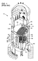
- FIG. 1 One type of nuclear reactor, a conventional boiling water reactor (BWR) is shown in Figure 1 .
- BWR boiling water reactor
- RPV reactor pressure vessel
- Feedwater is admitted into the RPV 10 via a feedwater inlet 15 and a feedwater sparger pipe 20, which is adjacent a core spray line 105.
- the feedwater flows downwardly through a downcomer annulus 25, which is an annular region between RPV 10 and a core shroud 30.
- the core shroud 30 is a stainless steel cylinder that surrounds the nuclear fuel core 35, which includes a plurality of fuel bundle assemblies 40 (only a few are illustrated in Figure 1 ).
- a top guide 45 and a core plate 50 supports each of the fuel bundle assemblies 40.
- the coolant water flows downward through the downcomer annulus 25 and into the core lower plenum 55. Then the water in the core lower plenum 55 flows upward through the nuclear fuel core 35. In particular, water enters the fuel bundle assemblies 40, wherein a boiling boundary layer is established. A mixture of water and steam exits the nuclear fuel core 35 and enters the core upper plenum 60 under the shroud head 65. The steam-water mixture then flows through standpipes 70 on top of the shroud head 65 and enters the steam separators 75, which separate water from steam. The separated water is recirculated back to the downcomer annulus 25 and the steam flows out of the RPV 10 and to a steam turbine, or the like, (not illustrated).
- the BWR also includes a coolant recirculation system, which provides the forced convection flow through the nuclear fuel core 35 necessary to attain the required power density.
- a portion of the water is drawn from the lower end of the downcomer annulus 25 via recirculation water outlet 80 and forced by a recirculation pump (not illustrated) into a plurality of jet pump assemblies 85 (one is illustrated in Figure 1 ) via recirculation water inlets 90.
- the jet pump assemblies 85 are typically circumferentially distributed around the core shroud 30 and provide the required reactor core flow.
- a typical BWR has sixteen to twenty-four inlet mixers 95.
- a conventional jet pump assembly 85 comprises a pair of inlet mixers 95.
- Each inlet mixer 95 has an elbow welded thereto, which receives pressurized driving water from a recirculation pump (not illustrated) via an inlet riser 100.
- a type of inlet mixer 95 comprises a set of five nozzles circumferentially distributed at equal angles about the inlet mixer axis (not illustrated in the Figures).
- each nozzle is tapered radially inwardly at the nozzle outlet. This convergent nozzle energizes the jet pump assembly 85.
- a secondary inlet opening (not illustrated) is radially outside of the nozzle exits. Therefore, as jets of water exit the nozzles, water from the downcomer annulus 25 is drawn into the inlet mixer 95 via the secondary inlet opening, where mixing with water from the recirculation pump then occurs.
- the flow through the feedwater sparger pipe 20 contains pressure fluctuations from various sources in the reactor system. These pressure fluctuations can have frequencies close to one or more natural vibration modes of the feedwater sparger pipe 20.
- the vibration modes experienced by the feedwater sparger pipe 20 depends, in part on, on preload and welds on the lugs 110 (not illustrated in Figure 1 ) of the feedwater sparger pipe 20.
- the welds may also serve to keep the feedwater sparger pipe 20 at a specific distance away from the core spray line 105.
- US 2008/0296470 A1 relates to a method and apparatus for repairing a support for a jet pump line and discloses the use of a support clamp for sensing line repair, replacement and damage prevention or reduction.
- US2004/0022343 A1 discloses a clamp for a feedwater sparger end bracket, wherein the clamp comprises a bearing plate, an upper and a lower section, and a jacking bolt for connecting both sections.
- US 5,839,192 discloses a clamp for repairing a cracked core spray supply piping, wherein the clamp comprises an upper and a lower section
- an apparatus for dampening vibration experienced by a sparger pipe integrated with a structure within a reactor pressure vessel (RPV) of a nuclear power plant is provided, the apparatus being in accordance with claim 1 herein.
- RSV reactor pressure vessel
- a system for reducing the vibration experienced by a pipe within a nuclear reactor pressure vessel is provided, the system being in accordance with claim 8 herein.
- the present invention has the technical effect of reducing the level of vibration experienced by a feedwater sparger pipe 20.
- An embodiment of the present invention may provide support and a preload to the line at a new location or may replace an existing support, such as, but not limiting of, a weld; which may alter the natural frequencies to avoid resonance from occurring when the structure(s) is excited.
- An embodiment of the present invention provides at least one repair clamp that generally adds support, to the feedwater sparger pipe 20. After installation, the repair clamp may lower the amplitude of, and/or change the frequency of, the vibration experienced by the feedwater sparger pipe 20.
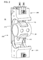
- Figure 2 is a schematic illustrating a partially exploded isometric view of an embodiment of a repair clamp 200 within an environment in the present invention operates.
- Figure 2 illustrates the repair clamp 200 partially surrounding a portion of the feedwater sparger pipe 20.
- the feedwater sparger pipe 20 includes a plurality of lugs 110.
- An embodiment of the repair clamp 200 comprises three main components.
- An upper section 205 for restraining a portion of the feedwater sparger pipe 20.
- a lower section 210 for restraining another portion of the feedwater sparger pipe 20 and for receiving a portion of the upper section 205.
- a bearing plate 215 for providing a barrier between the feedwater sparger pipe 20 and a wall of the RPV 10.
- the upper section 205 and the lower section 210 cooperatively operate to secure the feedwater sparger pipe 20 at a desired distance from the wall of the RPV 10 and from a surface of the core spray line 105.
- the repair clamp 200 may add or restore a preload to the feedwater sparger pipe 20, while changing the amplitude and/or frequency of the potential vibration.
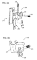
- Figures 3A-3B are schematics illustrating exploded isometric views of a repair clamp 200 in accordance with an embodiment of the present invention.
- Figure 3A illustrates embodiments of the upper section 205 and the bearing plate 215 with the present invention.
- Figure 3B illustrates an embodiment of the lower section 210 in with present invention.
- an embodiment of the upper section 205 may comprise: a second crimp collar 230, a second jacking bolt 235, a pinch plate 240, and at least one pinch bolt 245, all of which may assemble onto a upper clamp body 250 of the upper section 205 as illustrated, for example, but not limiting of, in Figure 3A .
- the second jacking bolt 235 serves to connect the upper clamp body 250 with the bearing plate 215.
- the second jacking bolt 235 may comprise a variety of forms.
- An embodiment of the second jacking bolt 235 may comprise a cylindrical shaft with a series of threads, or other groves, that allow for mating with the second crimp collar 230 and the upper clamp body 250.
- An end portion of the second jacking bolt 235 may allow for a hand tool to rotate the second jacking bolt 235.
- the end portion may allow for a wrench to fasten the second jacking bolt 235 to the upper clamp body 250.
- the second crimp collar 230 serves to fix the second jacking bolt 235 to a desired position. This may prevent the second jacking bolt 235 from loosening due to vibration after the repair clamp 200 is installed.
- An embodiment of the second crimp collar 230 may allow for the second jacking bolt 235 to pass through and mate with a portion of the upper clamp body 250, as illustrated, for example, but not limiting of, in Figure 3A .
- An embodiment of the second crimp collar 230 may also allow for the at least one pinch bolt 245 to pass through.
- the second crimp collar 230 may prevent the at least one pinch bolt 245 from loosening, due to vibration, after the repair clamp 200 is installed.
- the at least one pinch bolt 245 serves to apply a compressive load from the repair clamp 200 to the feedwater sparger pipe 20. Essentially, the at least one pinch bolt 245 clamps the upper section 205 and the lower section 210 around a portion of the feedwater sparger pipe 20.
- the upper clamp body 250 allows for the lug 110 to mate with a surface on the upper clamp body 250. This may allow for a robust connection between the repair clamp 200 and the feedwater sparger pipe 20.
- the pinch plate 240 may serve to provide a bearing surface between the at least one pinch bolt 245 and the second jacking bolt 235.
- the upper clamp body 250 may comprise a plurality of recesses allowing for the aforementioned upper section 205 components to mate therein.
- the upper section 205 may also comprise grooves for a top end of the bearing plate 215 to slidably attach.
- the upper clamp body 250 comprises a tang portion that allows for mating with the lower section 210, as described below.
- a surface of the upper clamp body 250 may be of a shape allowing for mating with the portion of the feedwater sparger pipe 20.
- the shape may comprise an arc of a similar radius of the outer diameter of the feedwater sparger pipe 20.
- the surface comprises a notch that allows for mating with the lug 110.
- the bearing plate 215 serves as a barrier between the repair clamp 200 and a wall of the RPV 10.
- the bearing plate 215 may form the rear of the repair clamp 200 encompassing the rear portions of the upper section 205 and the lower section 210.
- an overall length of the bearing plate 215 extends beyond an overall length of the upper section 205 mated with the lower section 210. This feature may allow for the applied forces of the second jacking bolt 235 and the first jacking bolt 225 to be transferred on the wall of the RPV 10.
- FIG. 3B illustrates an exploded view of the lower section 210.
- An embodiment of the lower section 210 may comprise a first crimp collar 220 and a first jacking bolt 225, both of which may be integrated with a lower clamp body 227.
- the first crimp collar 220 generally functions similar to that of the second crimp collar 230, as previously described.
- the first jacking bolt 225 generally functions similar to that of the second jacking bolt 235, as previously described.
- the lower clamp body 227 serves to receive and hold a portion of the feedwater sparger pipe 20.
- a first surface of the lower clamp body 227 integrates with the bearing plate 215.
- a second surface of the lower clamp body 227 may be of a shape allowing for mating with the portion of the feedwater sparger pipe 20.
- the shape may comprise an arc of a similar radius of the outer diameter of the feedwater sparger pipe 20.
- the second surface comprises a notch that allows for mating with the lug 110.
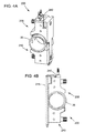
- Figures 4A-4B are schematics illustrating isometric and side elevation views of an assembled repair clamp 200 securing a portion of a feedwater sparger pipe 20 in accordance with an embodiment of the present invention.
- Figure 4A illustrates a side isometric view.
- Figure 4B illustrates an opposing side elevation view.
- Figure 4A specifically illustrates the upper section 205 and lower section 210 assembled clamping onto the feedwater sparger pipe 20.
- Figure 4A illustrates how the tang portion of the upper clamp body 250 slidably mates with the lower clamp body 227 in accordance with the present invention.
- Figure 4A also illustrates how the ends of the first jacking bolt 225 and the second jacking bolt 235 may extend through holes mating holes.
- the upper clamp body 250 may have a hole that allows the second jacking bolt 235 to extend through and engage the bearing plate 215.
- the lower clamp body 227 may comprise a recess or a notch that allows the tang portion of the upper clamp body 250 to fit therein. This may allow for the tang and a rear portion of the lower clamp body 227 to form the relatively flat rear portion of the lower section 210.
- an embodiment of the upper clamp body 250 comprises the tang portion having a hole that allows for the first jacking bolt 225 to extend through to engage the bearing plate 215.
- Figure 4A also illustrates how the position at least one pinch bolt 245 may be maintained by the second crimp collar 230.
- the second crimp collar 230 may be used to prevent loosening, as previously described.
- Figure 4B is an opposing side elevation view of Figure 4A.
- Figure 4B illustrates the repair clamp 200 having the bearing plate 215 and the pinch plate 240 connected to the upper section 205.
- the bearing plate 215 may serve as the back portion of the repair clamp 200.
- the pinch plate 240 may provide a barrier between the second crimp collar 230 and the bearing plate 215.
- Figure 4B also illustrates how the first jacking bolt 225 and the second jacking bolt 235 may reside within the respective crimp collar, 220, 230, as previously described.
- Figure 4B also illustrates how the upper section 205 and the lower section 210 may partially surround a portion of the feedwater sparger pipe 20.
- Figure 5 is a schematic illustrating a plan view elevation of a repair clamp 200 installed on a feedwater sparger pipe 20, in accordance with an embodiment of the present invention.
- Figure 5 illustrates a few of the benefits of an embodiment of the present invention.
- a first benefit allows for a generous clearance around the repair clamp 200.
- the repair clamp 200 may provide a vertical distance of between the feedwater sparger pipe 20 and the core spray line 105, represented by dimension "X” in Figure 5 .
- the repair clamp 200 may also provide a distance of between a bottom surface of the repair clamp 200 and the core spray line 105, represented by dimension "Y" in Figure 5 .
- the repair clamp 200 When fully engaged the repair clamp 200 may also provide a distance of between a side of the repair clamp 200 and a portion of the feedwater sparger pipe 20 represented by dimension "Z" in Figure 5 .
- the dimensional values and/or ranges of X, Y, and Z may be determined by the type of RPV 10 to which an embodiment of the repair clamp 200 is installed.
- a second benefit of the repair clamp 200 allows for a range of approximately 0.64 cm (0.250 inch) of adjustment. This may accommodate a broad range of feedwater sparger pipe 20 positions relative to a wall of the RPV 10.
- a third benefit involves the crimp collars 220,230, which may serve as a positive anti-rotation device.
- the crimp collars 220,230 may only require a visual inspection to confirm that the repair clamp 200 has not loosened.
- the components of an embodiment present invention may be formed of any material capable of withstanding the operating environment to which the repair clamp 200 may be exposed.
- the repair clamp 200 may clamp around the feedwater sparger pipe 20 at a location of previous jacking bolts. When fully engaged, the repair clamp 200 may provide for generous clearance around the upper bounds of the feedwater sparger pipe 20 tolerance and connecting welds. The repair clamp 200 may restore the preload on the feedwater sparger pipe 20 at the location of the previous jacking bolts. The repair clamp 200 may also reduce the vibration experience by the feedwater sparger pipe 20.
- an embodiment of the present invention may be used to: a) introduce a different vibration mode; b) to secure sparger pipe at a fixed distance away from a separate structure or other object; or c) to apply a compressive load to a sparger pipe.
Landscapes
- Engineering & Computer Science (AREA)
- General Engineering & Computer Science (AREA)
- Mechanical Engineering (AREA)
- Physics & Mathematics (AREA)
- Plasma & Fusion (AREA)
- High Energy & Nuclear Physics (AREA)
- Structure Of Emergency Protection For Nuclear Reactors (AREA)
- Physical Or Chemical Processes And Apparatus (AREA)
- Monitoring And Testing Of Nuclear Reactors (AREA)
Description
- The present application relates generally to nuclear reactors; and more particularly to, a system for dampening the level of vibration experienced by system piping within a nuclear reactor pressure vessel.
- One type of nuclear reactor, a conventional boiling water reactor (BWR) is shown in
Figure 1 . During operation of the reactor, coolant water circulating inside a reactor pressure vessel (RPV) 10 is heated by nuclear fission produced in thenuclear fuel core 35. Feedwater is admitted into the RPV 10 via afeedwater inlet 15 and afeedwater sparger pipe 20, which is adjacent acore spray line 105. The feedwater flows downwardly through adowncomer annulus 25, which is an annular region betweenRPV 10 and acore shroud 30. - The
core shroud 30 is a stainless steel cylinder that surrounds thenuclear fuel core 35, which includes a plurality of fuel bundle assemblies 40 (only a few are illustrated inFigure 1 ). Atop guide 45 and acore plate 50 supports each of thefuel bundle assemblies 40. - The coolant water flows downward through the
downcomer annulus 25 and into the corelower plenum 55. Then the water in the corelower plenum 55 flows upward through thenuclear fuel core 35. In particular, water enters thefuel bundle assemblies 40, wherein a boiling boundary layer is established. A mixture of water and steam exits thenuclear fuel core 35 and enters the coreupper plenum 60 under theshroud head 65. The steam-water mixture then flows throughstandpipes 70 on top of theshroud head 65 and enters thesteam separators 75, which separate water from steam. The separated water is recirculated back to thedowncomer annulus 25 and the steam flows out of theRPV 10 and to a steam turbine, or the like, (not illustrated). - The BWR also includes a coolant recirculation system, which provides the forced convection flow through the
nuclear fuel core 35 necessary to attain the required power density. A portion of the water is drawn from the lower end of thedowncomer annulus 25 viarecirculation water outlet 80 and forced by a recirculation pump (not illustrated) into a plurality of jet pump assemblies 85 (one is illustrated inFigure 1 ) viarecirculation water inlets 90. Thejet pump assemblies 85 are typically circumferentially distributed around thecore shroud 30 and provide the required reactor core flow. A typical BWR has sixteen to twenty-fourinlet mixers 95. - As illustrated in
Figure 1 , a conventionaljet pump assembly 85 comprises a pair ofinlet mixers 95. Eachinlet mixer 95 has an elbow welded thereto, which receives pressurized driving water from a recirculation pump (not illustrated) via aninlet riser 100. A type ofinlet mixer 95 comprises a set of five nozzles circumferentially distributed at equal angles about the inlet mixer axis (not illustrated in the Figures). Here, each nozzle is tapered radially inwardly at the nozzle outlet. This convergent nozzle energizes thejet pump assembly 85. A secondary inlet opening (not illustrated) is radially outside of the nozzle exits. Therefore, as jets of water exit the nozzles, water from thedowncomer annulus 25 is drawn into theinlet mixer 95 via the secondary inlet opening, where mixing with water from the recirculation pump then occurs. - During
RPV 10 operation, the flow through thefeedwater sparger pipe 20 contains pressure fluctuations from various sources in the reactor system. These pressure fluctuations can have frequencies close to one or more natural vibration modes of thefeedwater sparger pipe 20. The vibration modes experienced by thefeedwater sparger pipe 20 depends, in part on, on preload and welds on the lugs 110 (not illustrated inFigure 1 ) of thefeedwater sparger pipe 20. The welds may also serve to keep thefeedwater sparger pipe 20 at a specific distance away from thecore spray line 105. In addition to pressure fluctuations, there may be other sources of vibration that can have frequencies close to one or more natural vibration modes of thefeedwater sparger pipe 20. When an excitation frequency is near the natural frequencies of thefeedwater sparger pipe 20, the resulting vibration may crack the welds on thelugs 110 and remove the preload from thefeedwater sparger pipe 20. This can result in loss of the indication of core flow, which may require shutdown of theRPV 10. - There are a few possible problems with the currently known systems for dampening the vibration. Currently known systems involve re-welding the
lugs 110, which may lead to a repeat failure. These systems generally require longer installation time and expose operators to longer period of radioactivity. - For the aforementioned reasons, there is a need for a new system for dampening the vibration experienced by the
feedwater sparger pipe 20. The system should not require welding. The system should reduce the installation time and lower operator exposure to radioactivity. -
US 2008/0296470 A1 relates to a method and apparatus for repairing a support for a jet pump line and discloses the use of a support clamp for sensing line repair, replacement and damage prevention or reduction.
US2004/0022343 A1 discloses a clamp for a feedwater sparger end bracket, wherein the clamp comprises a bearing plate, an upper and a lower section, and a jacking bolt for connecting both sections.
US 5,839,192 discloses a clamp for repairing a cracked core spray supply piping, wherein the clamp comprises an upper and a lower section - In accordance with an embodiment of the present invention, an apparatus for dampening vibration experienced by a sparger pipe integrated with a structure within a reactor pressure vessel (RPV) of a nuclear power plant is provided, the apparatus being in accordance with claim 1 herein.
- In accordance with another embodiment of the present invention, a system for reducing the vibration experienced by a pipe within a nuclear reactor pressure vessel (RPV) is provided, the system being in accordance with claim 8 herein.
- There follows a detailed description of embodiments of the invention by way of example only with reference to the accompanying drawings, in which:
-
Figure 1 is a schematic illustrating the environment in which an embodiment of the present invention operates; -
Figure 2 is a schematic illustrating a partially exploded isometric view of an embodiment of a repair clamp within an environment in the present invention operates; -
Figures 3A-3B , collectivelyFigure 3 , are schematics illustrating exploded isometric views of a repair clamp in accordance with an embodiment of the present invention; -
Figures 4A-4B , collectivelyFigure 4 , are schematics illustrating isometric and side elevation views of an assembled repair clamp securing a portion of a feedwater sparger pipe in accordance with an embodiment of the present invention; and -
Figure 5 is a schematic illustrating a plan view of a repair clamp installed on a feedwater sparger pipe, in accordance with an embodiment of the present invention. - Certain terminology is used herein for convenience only and is not to be taken as a limitation on the invention. For example, words such as "upper," "lower," "left," "front", "right," "horizontal," "vertical," "upstream," "downstream," "fore", and "aft" merely describe the configuration shown in the Figures. Indeed, the components may be oriented in any direction and the terminology, therefore, should be understood as encompassing such variations unless specified otherwise. Furthermore, the following discussion focuses on an embodiment of the present invention integrated with the feedwater sparger system of the
RPV 10. - The present invention has the technical effect of reducing the level of vibration experienced by a
feedwater sparger pipe 20. An embodiment of the present invention may provide support and a preload to the line at a new location or may replace an existing support, such as, but not limiting of, a weld; which may alter the natural frequencies to avoid resonance from occurring when the structure(s) is excited. - An embodiment of the present invention provides at least one repair clamp that generally adds support, to the
feedwater sparger pipe 20. After installation, the repair clamp may lower the amplitude of, and/or change the frequency of, the vibration experienced by thefeedwater sparger pipe 20. - Referring again to the Figures, where the various numbers represent like parts throughout the several views.
Figure 2 is a schematic illustrating a partially exploded isometric view of an embodiment of arepair clamp 200 within an environment in the present invention operates.Figure 2 illustrates therepair clamp 200 partially surrounding a portion of thefeedwater sparger pipe 20. Thefeedwater sparger pipe 20 includes a plurality oflugs 110. - An embodiment of the
repair clamp 200 comprises three main components. Anupper section 205 for restraining a portion of thefeedwater sparger pipe 20. Alower section 210 for restraining another portion of thefeedwater sparger pipe 20 and for receiving a portion of theupper section 205. A bearingplate 215 for providing a barrier between thefeedwater sparger pipe 20 and a wall of theRPV 10. Generally, theupper section 205 and thelower section 210 cooperatively operate to secure thefeedwater sparger pipe 20 at a desired distance from the wall of theRPV 10 and from a surface of thecore spray line 105. When installed therepair clamp 200 may add or restore a preload to thefeedwater sparger pipe 20, while changing the amplitude and/or frequency of the potential vibration. -
Figures 3A-3B , collectivelyFigure 3 , are schematics illustrating exploded isometric views of arepair clamp 200 in accordance with an embodiment of the present invention.Figure 3A illustrates embodiments of theupper section 205 and thebearing plate 215 with the present invention.Figure 3B illustrates an embodiment of thelower section 210 in with present invention. - Referring now to
Figure 3A , an embodiment of theupper section 205 may comprise: asecond crimp collar 230, a second jackingbolt 235, apinch plate 240, and at least onepinch bolt 245, all of which may assemble onto aupper clamp body 250 of theupper section 205 as illustrated, for example, but not limiting of, inFigure 3A . The second jackingbolt 235 serves to connect theupper clamp body 250 with thebearing plate 215. The second jackingbolt 235 may comprise a variety of forms. An embodiment of the second jackingbolt 235 may comprise a cylindrical shaft with a series of threads, or other groves, that allow for mating with thesecond crimp collar 230 and theupper clamp body 250. An end portion of the second jackingbolt 235 may allow for a hand tool to rotate the second jackingbolt 235. For example, but not limiting of, the end portion may allow for a wrench to fasten the second jackingbolt 235 to theupper clamp body 250. - The
second crimp collar 230 serves to fix the second jackingbolt 235 to a desired position. This may prevent the second jackingbolt 235 from loosening due to vibration after therepair clamp 200 is installed. An embodiment of thesecond crimp collar 230 may allow for the second jackingbolt 235 to pass through and mate with a portion of theupper clamp body 250, as illustrated, for example, but not limiting of, inFigure 3A . An embodiment of thesecond crimp collar 230 may also allow for the at least onepinch bolt 245 to pass through. Here, thesecond crimp collar 230 may prevent the at least onepinch bolt 245 from loosening, due to vibration, after therepair clamp 200 is installed. - The at least one
pinch bolt 245 serves to apply a compressive load from therepair clamp 200 to thefeedwater sparger pipe 20. Essentially, the at least onepinch bolt 245 clamps theupper section 205 and thelower section 210 around a portion of thefeedwater sparger pipe 20. According to the invention, the upper clamp body 250 : allows for thelug 110 to mate with a surface on theupper clamp body 250. This may allow for a robust connection between therepair clamp 200 and thefeedwater sparger pipe 20. Thepinch plate 240 may serve to provide a bearing surface between the at least onepinch bolt 245 and the second jackingbolt 235. - As illustrated in
Figure 3A , theupper clamp body 250 may comprise a plurality of recesses allowing for the aforementionedupper section 205 components to mate therein. Theupper section 205 may also comprise grooves for a top end of thebearing plate 215 to slidably attach. Theupper clamp body 250 comprises a tang portion that allows for mating with thelower section 210, as described below. - A surface of the
upper clamp body 250 may be of a shape allowing for mating with the portion of thefeedwater sparger pipe 20. For example, but not limiting of, the shape may comprise an arc of a similar radius of the outer diameter of thefeedwater sparger pipe 20. Moreover, the surface comprises a notch that allows for mating with thelug 110. - The bearing
plate 215 serves as a barrier between therepair clamp 200 and a wall of theRPV 10. Generally, the bearingplate 215 may form the rear of therepair clamp 200 encompassing the rear portions of theupper section 205 and thelower section 210. In an embodiment of the present invention an overall length of thebearing plate 215 extends beyond an overall length of theupper section 205 mated with thelower section 210. This feature may allow for the applied forces of the second jackingbolt 235 and the first jackingbolt 225 to be transferred on the wall of theRPV 10. - Referring now to
Figure 3B that illustrates an exploded view of thelower section 210. An embodiment of thelower section 210 may comprise afirst crimp collar 220 and a first jackingbolt 225, both of which may be integrated with alower clamp body 227. Thefirst crimp collar 220 generally functions similar to that of thesecond crimp collar 230, as previously described. The first jackingbolt 225 generally functions similar to that of the second jackingbolt 235, as previously described. - The
lower clamp body 227 serves to receive and hold a portion of thefeedwater sparger pipe 20. A first surface of the lower clamp body 227 : integrates with thebearing plate 215. A second surface of thelower clamp body 227 may be of a shape allowing for mating with the portion of thefeedwater sparger pipe 20. For example, but not limiting of, the shape may comprise an arc of a similar radius of the outer diameter of thefeedwater sparger pipe 20. Moreover, the second surface comprises a notch that allows for mating with thelug 110. -
Figures 4A-4B , collectivelyFigure 4 , are schematics illustrating isometric and side elevation views of an assembledrepair clamp 200 securing a portion of afeedwater sparger pipe 20 in accordance with an embodiment of the present invention.Figure 4A illustrates a side isometric view.Figure 4B illustrates an opposing side elevation view. -
Figure 4A specifically illustrates theupper section 205 andlower section 210 assembled clamping onto thefeedwater sparger pipe 20. Here,Figure 4A illustrates how the tang portion of theupper clamp body 250 slidably mates with thelower clamp body 227 in accordance with the present invention. -
Figure 4A also illustrates how the ends of the first jackingbolt 225 and the second jackingbolt 235 may extend through holes mating holes. Specifically, theupper clamp body 250 may have a hole that allows the second jackingbolt 235 to extend through and engage thebearing plate 215. Also, thelower clamp body 227 may comprise a recess or a notch that allows the tang portion of theupper clamp body 250 to fit therein. This may allow for the tang and a rear portion of thelower clamp body 227 to form the relatively flat rear portion of thelower section 210. Here, an embodiment of theupper clamp body 250 comprises the tang portion having a hole that allows for the first jackingbolt 225 to extend through to engage thebearing plate 215. -
Figure 4A also illustrates how the position at least onepinch bolt 245 may be maintained by thesecond crimp collar 230. Here, after the at least onepinch bolt 245 provides the compressive load to secure thefeedwater sparger pipe 20, thesecond crimp collar 230 may be used to prevent loosening, as previously described. - Referring now to
Figure 4B , which is an opposing side elevation view ofFigure 4A. Figure 4B illustrates therepair clamp 200 having the bearingplate 215 and thepinch plate 240 connected to theupper section 205. As discussed, in an embodiment of the present invention thebearing plate 215 may serve as the back portion of therepair clamp 200. Also, thepinch plate 240 may provide a barrier between thesecond crimp collar 230 and thebearing plate 215.Figure 4B also illustrates how the first jackingbolt 225 and the second jackingbolt 235 may reside within the respective crimp collar, 220, 230, as previously described.Figure 4B also illustrates how theupper section 205 and thelower section 210 may partially surround a portion of thefeedwater sparger pipe 20. -
Figure 5 is a schematic illustrating a plan view elevation of arepair clamp 200 installed on afeedwater sparger pipe 20, in accordance with an embodiment of the present invention.Figure 5 illustrates a few of the benefits of an embodiment of the present invention. A first benefit allows for a generous clearance around therepair clamp 200. When fully engaged therepair clamp 200 may provide a vertical distance of between thefeedwater sparger pipe 20 and thecore spray line 105, represented by dimension "X" inFigure 5 . When fully engaged therepair clamp 200 may also provide a distance of between a bottom surface of therepair clamp 200 and thecore spray line 105, represented by dimension "Y" inFigure 5 . When fully engaged therepair clamp 200 may also provide a distance of between a side of therepair clamp 200 and a portion of thefeedwater sparger pipe 20 represented by dimension "Z" inFigure 5 . The dimensional values and/or ranges of X, Y, and Z may be determined by the type ofRPV 10 to which an embodiment of therepair clamp 200 is installed. - A second benefit of the
repair clamp 200 allows for a range of approximately 0.64 cm (0.250 inch) of adjustment. This may accommodate a broad range offeedwater sparger pipe 20 positions relative to a wall of theRPV 10. - A third benefit involves the crimp collars 220,230, which may serve as a positive anti-rotation device. The crimp collars 220,230 may only require a visual inspection to confirm that the
repair clamp 200 has not loosened. - The components of an embodiment present invention may be formed of any material capable of withstanding the operating environment to which the
repair clamp 200 may be exposed. - In use, the
repair clamp 200 may clamp around thefeedwater sparger pipe 20 at a location of previous jacking bolts. When fully engaged, therepair clamp 200 may provide for generous clearance around the upper bounds of thefeedwater sparger pipe 20 tolerance and connecting welds. Therepair clamp 200 may restore the preload on thefeedwater sparger pipe 20 at the location of the previous jacking bolts. Therepair clamp 200 may also reduce the vibration experience by thefeedwater sparger pipe 20. - Although the present invention has been shown and described in considerable detail with respect to only a few exemplary embodiments thereof, it should be understood by those skilled in the art that we do not intend to limit the invention to the embodiments since various modifications may be made to the disclosed embodiments within the scope of the invention as defined by the following claims. For example, but not limiting of, an embodiment of the present invention may be used to: a) introduce a different vibration mode; b) to secure sparger pipe at a fixed distance away from a separate structure or other object; or c) to apply a compressive load to a sparger pipe.
Claims (8)
- An apparatus (200) for dampening vibration experienced by a sparger pipe (20) integrated with a structure within a reactor pressure vessel (RPV) (10) of a nuclear power plant; wherein the apparatus comprises:a bearing plate (215) configured for providing a barrier between a sparger pipe (20) and a structure, wherein the structure is located within a reactor pressure vessel (RPV) (10) of a nuclear power plant, and wherein the sparger pipe (20) comprises an upper lug (110) and a lower lug (110) located on an outer surface of the sparger pipe (20);a lower section (210) for holding a portion of the sparger pipe (20), the lower section comprising: a first jacking bolt (225); a first crimp collar (220) for securing a position of the first jacking bolt (225) and for affixing the first jacking bolt (225) to a designated position; a first lower surface that integrates with the bearing plate (215); and a second lower surface for holding a portion of the sparger pipe (20), wherein the second lower surface comprises a lower notch for mating with the lower lug (110);an upper section (205) slidably connected to the lower section (210) for holding another portion of the sparger pipe (20), the upper section comprising: a hole, wherein the first jacking bolt (225) is configured to move through the lower section (210), then the hole, and then terminate at a portion of the bearing plate (215) so as to connect the upper section (205) to the lower section (210); a first upper surface that integrates with the bearing plate (215); and a second upper surface for holding a portion of the sparger pipe (20), wherein the second upper surface comprises an upper notch for mating with the upper lug (110);wherein the lower section (210), the upper section (205) and the bearing plate (215) cooperatively secure the sparger pipe (20) at a distance from a facing surface of the bearing plate (215), and allow for dampening of a vibration experienced by the sparger pipe (20).
- The apparatus of claim 1, wherein the upper section (205) comprises:a second jacking bolt (235) for affixing the upper section (205) to the bearing plate (215), wherein the second jacking bolt (235) is secured by a second crimp collar (230); andat least one pinch bolt (245) for clamping the upper section (205) and the lower section (210) to the sparger pipe (20), wherein the at least one pinch bolt (245) is secured by the second crimp collar (230).
- The apparatus of claim 2, further comprising a pinch plate (240), wherein the pinch plate (240) provides a bearing surface between the at least one pinch bolt (245) and the second jacking bolt (235).
- The apparatus of claim 3, wherein the upper section (205) comprises a cavity that allows for a portion of the second crimp collar (230), a portion of the bearing plate (215), and a portion of the pinch plate (240) to reside.
- The apparatus of any of the preceding claims, wherein a length of the bearing plate (215) extends beyond a combined length of the upper section (205) and the lower section (210) when the upper section (205) is integrated with the lower section (210).
- The apparatus of claim 2, wherein a compressive load applied to the upper section (205) and the lower section (210) by the at least one pinch bolt (245) restricts the movement of the upper lug (110) and the lower lug (110).
- The apparatus of claim 6, wherein the compressive load applied to the upper section (205) and the lower section (210) by at least one pinch bolt (245) restores a preload onto the sparger pipe (20).
- A system for reducing the vibration experienced by a pipe within a nuclear reactor pressure vessel (RPV), the system comprising:a nuclear fuel core (35) comprising a plurality of fuel bundle assemblies (40);a feedwater inlet (15);a feedwater sparger pipe (20);a core spray line (105); anda clamp (200) corresponding to the apparatus of any of the preceding claims;wherein the clamp is connected to a portion of the feedwater sparger pipe (20) to reduce a level of vibration experience by the feedwater sparger pipe; and wherein the clamp applies a compressive load to the feedwater sparger pipe and positions the feedwater sparger pipe at a distance from the core spray line (105).
Applications Claiming Priority (1)
| Application Number | Priority Date | Filing Date | Title |
|---|---|---|---|
| US12/414,129 US8194815B2 (en) | 2009-03-30 | 2009-03-30 | Apparatus and system for dampening the vibration experienced by an object |
Publications (3)
| Publication Number | Publication Date |
|---|---|
| EP2236883A2 EP2236883A2 (en) | 2010-10-06 |
| EP2236883A3 EP2236883A3 (en) | 2013-11-27 |
| EP2236883B1 true EP2236883B1 (en) | 2014-12-10 |
Family
ID=42263734
Family Applications (1)
| Application Number | Title | Priority Date | Filing Date |
|---|---|---|---|
| EP10156869.9A Active EP2236883B1 (en) | 2009-03-30 | 2010-03-18 | Apparatus and system for dampening the vibration experienced by a sprager pipe |
Country Status (6)
| Country | Link |
|---|---|
| US (1) | US8194815B2 (en) |
| EP (1) | EP2236883B1 (en) |
| JP (1) | JP5108910B2 (en) |
| ES (1) | ES2527921T3 (en) |
| MX (1) | MX2010003456A (en) |
| TW (1) | TWI474341B (en) |
Families Citing this family (12)
| Publication number | Priority date | Publication date | Assignee | Title |
|---|---|---|---|---|
| US8422618B2 (en) * | 2009-12-08 | 2013-04-16 | Ge-Hitachi Nuclear Energy Americas Llc | Apparatus and system for restricting the movement of a component |
| US20120032064A1 (en) * | 2010-08-04 | 2012-02-09 | Ge-Hitachi Nuclear Energy Americas Llc | Method and apparatus for a bwr jet pump support system |
| US8731127B2 (en) | 2010-08-04 | 2014-05-20 | Ge-Hitachi Nuclear Energy Americas, Llc | Method and apparatus for a BWR inlet mixer clamp assembly |
| US8731134B2 (en) | 2010-08-06 | 2014-05-20 | Ge-Hitachi Nuclear Energy Americas Llc | Method and apparatus for a BWR jet pump inlet mixer support |
| RU2455452C1 (en) * | 2010-11-30 | 2012-07-10 | Мавлитзян Сагитьянович Габдрахимов | Vibration damper of stretching, compressing and torsion oscillations |
| ES2356223B1 (en) * | 2010-12-17 | 2012-02-06 | Schneider Electric España S.A. | EXTENSIBLE FLANGE FOR SURFACE CHANNELS AND ASSEMBLY PROCEDURES AND REFORM OF CHANNELS THAT INCLUDE SUCH FLANGE. |
| US9064609B2 (en) | 2012-05-16 | 2015-06-23 | Ge-Hitachi Nuclear Energy Americas Llc | Mechanical connections and methods |
| US9887016B2 (en) * | 2014-04-07 | 2018-02-06 | Areva Inc. | BWR feedwater sparger end bracket pin clamp |
| JP6510278B2 (en) | 2015-03-10 | 2019-05-08 | 三菱日立パワーシステムズ株式会社 | Condenser |
| US11014114B2 (en) * | 2018-07-25 | 2021-05-25 | Westinghouse Electric Company Llc | Feedwater sparger repair |
| CN112944043B (en) * | 2021-03-17 | 2025-04-01 | 苏州热工研究院有限公司 | Dynamic vibration absorber for pipelines |
| US20250266177A1 (en) * | 2024-02-20 | 2025-08-21 | Nuscale Power, Llc | Weld down pipe and tube support base |
Family Cites Families (15)
| Publication number | Priority date | Publication date | Assignee | Title |
|---|---|---|---|---|
| US4185802A (en) * | 1978-09-13 | 1980-01-29 | Fischer Sherman, Inc. | Anti-vibration pad for pipe support clamp |
| JPS55101899A (en) * | 1979-01-31 | 1980-08-04 | Tokyo Shibaura Electric Co | Method of fixing inncore pipe |
| JPS60107483U (en) * | 1983-12-23 | 1985-07-22 | 石川島播磨重工業株式会社 | Piping support device |
| JPS6158784U (en) * | 1984-09-25 | 1986-04-19 | ||
| US5544849A (en) * | 1994-11-04 | 1996-08-13 | General Electric Company | Swaged wear sleeve and method |
| US5839192A (en) * | 1996-11-27 | 1998-11-24 | Mpr Associates, Inc. | Method and apparatus for repairing cracked core spray supply piping in a boiling water reactor |
| US6086120A (en) * | 1997-12-05 | 2000-07-11 | General Electric Company | Methods and apparatus for performing jet pump riser pipe repairs |
| US6108391A (en) * | 1998-03-20 | 2000-08-22 | General Electric Company | Apparatus for performing jet pump riser pipe repairs |
| JP2001242278A (en) * | 2000-02-28 | 2001-09-07 | Hitachi Ltd | Reinforcement method of core sparger |
| JP2002156483A (en) * | 2000-11-16 | 2002-05-31 | Toshiba Corp | Internal pump stress reduction device |
| US20040022343A1 (en) * | 2001-01-30 | 2004-02-05 | Butler Patrick J. | Clamp for feedwater sparger end bracket assemblies and method of preventing separation of feedwater sparger end bracket assemblies |
| US6456682B1 (en) * | 2001-03-13 | 2002-09-24 | General Electric Company | Core spray sparger T-box attachment with clamp |
| US7724863B2 (en) * | 2004-10-14 | 2010-05-25 | General Electric Company | Core spray sparger T-box clamp apparatus and method for installing the same |
| US7467766B2 (en) * | 2006-08-18 | 2008-12-23 | Pothanikat John J | Acoustic dampening pipe shoe |
| US8548114B2 (en) * | 2007-05-30 | 2013-10-01 | General Electric Company | Method and apparatus for repairing a jet pump line support |
-
2009
- 2009-03-30 US US12/414,129 patent/US8194815B2/en active Active - Reinstated
-
2010
- 2010-03-18 ES ES10156869.9T patent/ES2527921T3/en active Active
- 2010-03-18 EP EP10156869.9A patent/EP2236883B1/en active Active
- 2010-03-18 TW TW99108030A patent/TWI474341B/en active
- 2010-03-26 MX MX2010003456A patent/MX2010003456A/en active IP Right Grant
- 2010-03-30 JP JP2010076541A patent/JP5108910B2/en active Active
Also Published As
| Publication number | Publication date |
|---|---|
| US8194815B2 (en) | 2012-06-05 |
| US20100246744A1 (en) | 2010-09-30 |
| JP2010237212A (en) | 2010-10-21 |
| EP2236883A2 (en) | 2010-10-06 |
| TWI474341B (en) | 2015-02-21 |
| TW201103037A (en) | 2011-01-16 |
| JP5108910B2 (en) | 2012-12-26 |
| MX2010003456A (en) | 2010-09-29 |
| ES2527921T3 (en) | 2015-02-02 |
| EP2236883A3 (en) | 2013-11-27 |
Similar Documents
| Publication | Publication Date | Title |
|---|---|---|
| US8194815B2 (en) | Apparatus and system for dampening the vibration experienced by an object | |
| US5521951A (en) | Reactor core shroud repair with tapered pins | |
| US5502754A (en) | Lateral restraint for core plate of boiling water reactor | |
| JP5032404B2 (en) | Fixing device for measuring pipe in reactor and fixing method using the same | |
| US5752807A (en) | Jet pump sensing line repair | |
| US8391437B2 (en) | Jet pump riser brace clamp | |
| US8170174B1 (en) | Simplified jet pump riser brace clamp | |
| EP2287857B1 (en) | System for dampening vibration | |
| US6434208B1 (en) | Jet pump beam lock | |
| US10760603B2 (en) | Apparatuses and methods for structurally replacing cracked welds in nuclear power plants | |
| US9959943B2 (en) | Method and apparatuses for operating and repairing nuclear reactors | |
| US6343107B1 (en) | Shroud repair apparatus | |
| US8210491B2 (en) | System for dampening the vibration experienced by a line | |
| EP2097664B1 (en) | A mechanical assembly for securing the structural integrity of a pipe joint | |
| EP2237282A2 (en) | Steam flow vortex straightener | |
| US8213562B2 (en) | Control rod blade extension for a nordic nuclear reactor |
Legal Events
| Date | Code | Title | Description |
|---|---|---|---|
| PUAI | Public reference made under article 153(3) epc to a published international application that has entered the european phase |
Free format text: ORIGINAL CODE: 0009012 |
|
| AK | Designated contracting states |
Kind code of ref document: A2 Designated state(s): AT BE BG CH CY CZ DE DK EE ES FI FR GB GR HR HU IE IS IT LI LT LU LV MC MK MT NL NO PL PT RO SE SI SK SM TR |
|
| REG | Reference to a national code |
Ref country code: DE Ref legal event code: R079 Ref document number: 602010020834 Country of ref document: DE Free format text: PREVIOUS MAIN CLASS: F16L0003000000 Ipc: G21C0015000000 |
|
| PUAL | Search report despatched |
Free format text: ORIGINAL CODE: 0009013 |
|
| AK | Designated contracting states |
Kind code of ref document: A3 Designated state(s): AT BE BG CH CY CZ DE DK EE ES FI FR GB GR HR HU IE IS IT LI LT LU LV MC MK MT NL NO PL PT RO SE SI SK SM TR |
|
| RIC1 | Information provided on ipc code assigned before grant |
Ipc: F16L 3/10 20060101ALI20131024BHEP Ipc: F16L 55/035 20060101ALI20131024BHEP Ipc: G21C 15/00 20060101AFI20131024BHEP Ipc: G21C 13/032 20060101ALI20131024BHEP |
|
| 17P | Request for examination filed |
Effective date: 20140527 |
|
| RBV | Designated contracting states (corrected) |
Designated state(s): AT BE BG CH CY CZ DE DK EE ES FI FR GB GR HR HU IE IS IT LI LT LU LV MC MK MT NL NO PL PT RO SE SI SK SM TR |
|
| GRAP | Despatch of communication of intention to grant a patent |
Free format text: ORIGINAL CODE: EPIDOSNIGR1 |
|
| INTG | Intention to grant announced |
Effective date: 20140718 |
|
| GRAS | Grant fee paid |
Free format text: ORIGINAL CODE: EPIDOSNIGR3 |
|
| GRAA | (expected) grant |
Free format text: ORIGINAL CODE: 0009210 |
|
| AK | Designated contracting states |
Kind code of ref document: B1 Designated state(s): AT BE BG CH CY CZ DE DK EE ES FI FR GB GR HR HU IE IS IT LI LT LU LV MC MK MT NL NO PL PT RO SE SI SK SM TR |
|
| REG | Reference to a national code |
Ref country code: GB Ref legal event code: FG4D |
|
| REG | Reference to a national code |
Ref country code: CH Ref legal event code: EP |
|
| REG | Reference to a national code |
Ref country code: IE Ref legal event code: FG4D |
|
| REG | Reference to a national code |
Ref country code: AT Ref legal event code: REF Ref document number: 701005 Country of ref document: AT Kind code of ref document: T Effective date: 20150115 |
|
| REG | Reference to a national code |
Ref country code: DE Ref legal event code: R096 Ref document number: 602010020834 Country of ref document: DE Effective date: 20150122 |
|
| REG | Reference to a national code |
Ref country code: ES Ref legal event code: FG2A Ref document number: 2527921 Country of ref document: ES Kind code of ref document: T3 Effective date: 20150202 |
|
| REG | Reference to a national code |
Ref country code: SE Ref legal event code: TRGR |
|
| REG | Reference to a national code |
Ref country code: AT Ref legal event code: MK05 Ref document number: 701005 Country of ref document: AT Kind code of ref document: T Effective date: 20141210 Ref country code: NL Ref legal event code: VDEP Effective date: 20141210 |
|
| REG | Reference to a national code |
Ref country code: NL Ref legal event code: VDEP Effective date: 20141210 |
|
| PG25 | Lapsed in a contracting state [announced via postgrant information from national office to epo] |
Ref country code: NO Free format text: LAPSE BECAUSE OF FAILURE TO SUBMIT A TRANSLATION OF THE DESCRIPTION OR TO PAY THE FEE WITHIN THE PRESCRIBED TIME-LIMIT Effective date: 20150310 Ref country code: LT Free format text: LAPSE BECAUSE OF FAILURE TO SUBMIT A TRANSLATION OF THE DESCRIPTION OR TO PAY THE FEE WITHIN THE PRESCRIBED TIME-LIMIT Effective date: 20141210 |
|
| REG | Reference to a national code |
Ref country code: LT Ref legal event code: MG4D |
|
| PG25 | Lapsed in a contracting state [announced via postgrant information from national office to epo] |
Ref country code: HR Free format text: LAPSE BECAUSE OF FAILURE TO SUBMIT A TRANSLATION OF THE DESCRIPTION OR TO PAY THE FEE WITHIN THE PRESCRIBED TIME-LIMIT Effective date: 20141210 Ref country code: GR Free format text: LAPSE BECAUSE OF FAILURE TO SUBMIT A TRANSLATION OF THE DESCRIPTION OR TO PAY THE FEE WITHIN THE PRESCRIBED TIME-LIMIT Effective date: 20150311 Ref country code: AT Free format text: LAPSE BECAUSE OF FAILURE TO SUBMIT A TRANSLATION OF THE DESCRIPTION OR TO PAY THE FEE WITHIN THE PRESCRIBED TIME-LIMIT Effective date: 20141210 Ref country code: LV Free format text: LAPSE BECAUSE OF FAILURE TO SUBMIT A TRANSLATION OF THE DESCRIPTION OR TO PAY THE FEE WITHIN THE PRESCRIBED TIME-LIMIT Effective date: 20141210 |
|
| PG25 | Lapsed in a contracting state [announced via postgrant information from national office to epo] |
Ref country code: NL Free format text: LAPSE BECAUSE OF FAILURE TO SUBMIT A TRANSLATION OF THE DESCRIPTION OR TO PAY THE FEE WITHIN THE PRESCRIBED TIME-LIMIT Effective date: 20141210 |
|
| PG25 | Lapsed in a contracting state [announced via postgrant information from national office to epo] |
Ref country code: PT Free format text: LAPSE BECAUSE OF FAILURE TO SUBMIT A TRANSLATION OF THE DESCRIPTION OR TO PAY THE FEE WITHIN THE PRESCRIBED TIME-LIMIT Effective date: 20150410 Ref country code: CZ Free format text: LAPSE BECAUSE OF FAILURE TO SUBMIT A TRANSLATION OF THE DESCRIPTION OR TO PAY THE FEE WITHIN THE PRESCRIBED TIME-LIMIT Effective date: 20141210 Ref country code: EE Free format text: LAPSE BECAUSE OF FAILURE TO SUBMIT A TRANSLATION OF THE DESCRIPTION OR TO PAY THE FEE WITHIN THE PRESCRIBED TIME-LIMIT Effective date: 20141210 Ref country code: RO Free format text: LAPSE BECAUSE OF FAILURE TO SUBMIT A TRANSLATION OF THE DESCRIPTION OR TO PAY THE FEE WITHIN THE PRESCRIBED TIME-LIMIT Effective date: 20141210 Ref country code: SK Free format text: LAPSE BECAUSE OF FAILURE TO SUBMIT A TRANSLATION OF THE DESCRIPTION OR TO PAY THE FEE WITHIN THE PRESCRIBED TIME-LIMIT Effective date: 20141210 |
|
| PG25 | Lapsed in a contracting state [announced via postgrant information from national office to epo] |
Ref country code: IS Free format text: LAPSE BECAUSE OF FAILURE TO SUBMIT A TRANSLATION OF THE DESCRIPTION OR TO PAY THE FEE WITHIN THE PRESCRIBED TIME-LIMIT Effective date: 20150410 Ref country code: PL Free format text: LAPSE BECAUSE OF FAILURE TO SUBMIT A TRANSLATION OF THE DESCRIPTION OR TO PAY THE FEE WITHIN THE PRESCRIBED TIME-LIMIT Effective date: 20141210 |
|
| REG | Reference to a national code |
Ref country code: DE Ref legal event code: R097 Ref document number: 602010020834 Country of ref document: DE |
|
| PLBE | No opposition filed within time limit |
Free format text: ORIGINAL CODE: 0009261 |
|
| STAA | Information on the status of an ep patent application or granted ep patent |
Free format text: STATUS: NO OPPOSITION FILED WITHIN TIME LIMIT |
|
| PG25 | Lapsed in a contracting state [announced via postgrant information from national office to epo] |
Ref country code: MC Free format text: LAPSE BECAUSE OF FAILURE TO SUBMIT A TRANSLATION OF THE DESCRIPTION OR TO PAY THE FEE WITHIN THE PRESCRIBED TIME-LIMIT Effective date: 20141210 Ref country code: LU Free format text: LAPSE BECAUSE OF FAILURE TO SUBMIT A TRANSLATION OF THE DESCRIPTION OR TO PAY THE FEE WITHIN THE PRESCRIBED TIME-LIMIT Effective date: 20150318 Ref country code: DK Free format text: LAPSE BECAUSE OF FAILURE TO SUBMIT A TRANSLATION OF THE DESCRIPTION OR TO PAY THE FEE WITHIN THE PRESCRIBED TIME-LIMIT Effective date: 20141210 |
|
| 26N | No opposition filed |
Effective date: 20150911 |
|
| GBPC | Gb: european patent ceased through non-payment of renewal fee |
Effective date: 20150318 |
|
| PG25 | Lapsed in a contracting state [announced via postgrant information from national office to epo] |
Ref country code: IT Free format text: LAPSE BECAUSE OF FAILURE TO SUBMIT A TRANSLATION OF THE DESCRIPTION OR TO PAY THE FEE WITHIN THE PRESCRIBED TIME-LIMIT Effective date: 20141210 |
|
| REG | Reference to a national code |
Ref country code: FR Ref legal event code: ST Effective date: 20151130 |
|
| REG | Reference to a national code |
Ref country code: IE Ref legal event code: MM4A |
|
| PG25 | Lapsed in a contracting state [announced via postgrant information from national office to epo] |
Ref country code: GB Free format text: LAPSE BECAUSE OF NON-PAYMENT OF DUE FEES Effective date: 20150318 Ref country code: IE Free format text: LAPSE BECAUSE OF NON-PAYMENT OF DUE FEES Effective date: 20150318 |
|
| PG25 | Lapsed in a contracting state [announced via postgrant information from national office to epo] |
Ref country code: FR Free format text: LAPSE BECAUSE OF NON-PAYMENT OF DUE FEES Effective date: 20150331 Ref country code: SI Free format text: LAPSE BECAUSE OF FAILURE TO SUBMIT A TRANSLATION OF THE DESCRIPTION OR TO PAY THE FEE WITHIN THE PRESCRIBED TIME-LIMIT Effective date: 20141210 |
|
| PG25 | Lapsed in a contracting state [announced via postgrant information from national office to epo] |
Ref country code: BE Free format text: LAPSE BECAUSE OF FAILURE TO SUBMIT A TRANSLATION OF THE DESCRIPTION OR TO PAY THE FEE WITHIN THE PRESCRIBED TIME-LIMIT Effective date: 20141210 |
|
| PG25 | Lapsed in a contracting state [announced via postgrant information from national office to epo] |
Ref country code: MT Free format text: LAPSE BECAUSE OF FAILURE TO SUBMIT A TRANSLATION OF THE DESCRIPTION OR TO PAY THE FEE WITHIN THE PRESCRIBED TIME-LIMIT Effective date: 20141210 |
|
| PG25 | Lapsed in a contracting state [announced via postgrant information from national office to epo] |
Ref country code: SM Free format text: LAPSE BECAUSE OF FAILURE TO SUBMIT A TRANSLATION OF THE DESCRIPTION OR TO PAY THE FEE WITHIN THE PRESCRIBED TIME-LIMIT Effective date: 20141210 Ref country code: BG Free format text: LAPSE BECAUSE OF FAILURE TO SUBMIT A TRANSLATION OF THE DESCRIPTION OR TO PAY THE FEE WITHIN THE PRESCRIBED TIME-LIMIT Effective date: 20141210 Ref country code: HU Free format text: LAPSE BECAUSE OF FAILURE TO SUBMIT A TRANSLATION OF THE DESCRIPTION OR TO PAY THE FEE WITHIN THE PRESCRIBED TIME-LIMIT; INVALID AB INITIO Effective date: 20100318 |
|
| PG25 | Lapsed in a contracting state [announced via postgrant information from national office to epo] |
Ref country code: CY Free format text: LAPSE BECAUSE OF FAILURE TO SUBMIT A TRANSLATION OF THE DESCRIPTION OR TO PAY THE FEE WITHIN THE PRESCRIBED TIME-LIMIT Effective date: 20141210 |
|
| PG25 | Lapsed in a contracting state [announced via postgrant information from national office to epo] |
Ref country code: TR Free format text: LAPSE BECAUSE OF FAILURE TO SUBMIT A TRANSLATION OF THE DESCRIPTION OR TO PAY THE FEE WITHIN THE PRESCRIBED TIME-LIMIT Effective date: 20141210 |
|
| PG25 | Lapsed in a contracting state [announced via postgrant information from national office to epo] |
Ref country code: MK Free format text: LAPSE BECAUSE OF FAILURE TO SUBMIT A TRANSLATION OF THE DESCRIPTION OR TO PAY THE FEE WITHIN THE PRESCRIBED TIME-LIMIT Effective date: 20141210 |
|
| REG | Reference to a national code |
Ref country code: CH Ref legal event code: U11 Free format text: ST27 STATUS EVENT CODE: U-0-0-U10-U11 (AS PROVIDED BY THE NATIONAL OFFICE) Effective date: 20260401 |
|
| PGFP | Annual fee paid to national office [announced via postgrant information from national office to epo] |
Ref country code: SE Payment date: 20260219 Year of fee payment: 17 |
|
| PGFP | Annual fee paid to national office [announced via postgrant information from national office to epo] |
Ref country code: DE Payment date: 20260219 Year of fee payment: 17 |
|
| PGFP | Annual fee paid to national office [announced via postgrant information from national office to epo] |
Ref country code: FI Payment date: 20260219 Year of fee payment: 17 |
|
| PGFP | Annual fee paid to national office [announced via postgrant information from national office to epo] |
Ref country code: ES Payment date: 20260401 Year of fee payment: 17 |
|
| PGFP | Annual fee paid to national office [announced via postgrant information from national office to epo] |
Ref country code: CH Payment date: 20260401 Year of fee payment: 17 |