EP2236768A2 - Turbomachine seal assembly - Google Patents
Turbomachine seal assembly Download PDFInfo
- Publication number
- EP2236768A2 EP2236768A2 EP10155312A EP10155312A EP2236768A2 EP 2236768 A2 EP2236768 A2 EP 2236768A2 EP 10155312 A EP10155312 A EP 10155312A EP 10155312 A EP10155312 A EP 10155312A EP 2236768 A2 EP2236768 A2 EP 2236768A2
- Authority
- EP
- European Patent Office
- Prior art keywords
- seal
- wheel
- machine
- bucket
- coverplate
- Prior art date
- Legal status (The legal status is an assumption and is not a legal conclusion. Google has not performed a legal analysis and makes no representation as to the accuracy of the status listed.)
- Withdrawn
Links
- 238000010926 purge Methods 0.000 description 8
- 238000001816 cooling Methods 0.000 description 5
- 238000012423 maintenance Methods 0.000 description 4
- 238000009434 installation Methods 0.000 description 3
- 241000879887 Cyrtopleura costata Species 0.000 description 2
- 230000037406 food intake Effects 0.000 description 2
- 241000725175 Caladium bicolor Species 0.000 description 1
- 235000015966 Pleurocybella porrigens Nutrition 0.000 description 1
- 230000004888 barrier function Effects 0.000 description 1
- 238000013016 damping Methods 0.000 description 1
- 210000001503 joint Anatomy 0.000 description 1
- 238000012986 modification Methods 0.000 description 1
- 230000004048 modification Effects 0.000 description 1
- 238000011144 upstream manufacturing Methods 0.000 description 1
Images

Classifications
-
- F—MECHANICAL ENGINEERING; LIGHTING; HEATING; WEAPONS; BLASTING
- F01—MACHINES OR ENGINES IN GENERAL; ENGINE PLANTS IN GENERAL; STEAM ENGINES
- F01D—NON-POSITIVE DISPLACEMENT MACHINES OR ENGINES, e.g. STEAM TURBINES
- F01D5/00—Blades; Blade-carrying members; Heating, heat-insulating, cooling or antivibration means on the blades or the members
- F01D5/02—Blade-carrying members, e.g. rotors
- F01D5/08—Heating, heat-insulating or cooling means
- F01D5/081—Cooling fluid being directed on the side of the rotor disc or at the roots of the blades
- F01D5/082—Cooling fluid being directed on the side of the rotor disc or at the roots of the blades on the side of the rotor disc
-
- F—MECHANICAL ENGINEERING; LIGHTING; HEATING; WEAPONS; BLASTING
- F01—MACHINES OR ENGINES IN GENERAL; ENGINE PLANTS IN GENERAL; STEAM ENGINES
- F01D—NON-POSITIVE DISPLACEMENT MACHINES OR ENGINES, e.g. STEAM TURBINES
- F01D11/00—Preventing or minimising internal leakage of working-fluid, e.g. between stages
- F01D11/005—Sealing means between non relatively rotating elements
- F01D11/006—Sealing the gap between rotor blades or blades and rotor
-
- F—MECHANICAL ENGINEERING; LIGHTING; HEATING; WEAPONS; BLASTING
- F01—MACHINES OR ENGINES IN GENERAL; ENGINE PLANTS IN GENERAL; STEAM ENGINES
- F01D—NON-POSITIVE DISPLACEMENT MACHINES OR ENGINES, e.g. STEAM TURBINES
- F01D11/00—Preventing or minimising internal leakage of working-fluid, e.g. between stages
- F01D11/02—Preventing or minimising internal leakage of working-fluid, e.g. between stages by non-contact sealings, e.g. of labyrinth type
- F01D11/04—Preventing or minimising internal leakage of working-fluid, e.g. between stages by non-contact sealings, e.g. of labyrinth type using sealing fluid, e.g. steam
-
- F—MECHANICAL ENGINEERING; LIGHTING; HEATING; WEAPONS; BLASTING
- F05—INDEXING SCHEMES RELATING TO ENGINES OR PUMPS IN VARIOUS SUBCLASSES OF CLASSES F01-F04
- F05D—INDEXING SCHEME FOR ASPECTS RELATING TO NON-POSITIVE-DISPLACEMENT MACHINES OR ENGINES, GAS-TURBINES OR JET-PROPULSION PLANTS
- F05D2240/00—Components
- F05D2240/55—Seals
-
- F—MECHANICAL ENGINEERING; LIGHTING; HEATING; WEAPONS; BLASTING
- F05—INDEXING SCHEMES RELATING TO ENGINES OR PUMPS IN VARIOUS SUBCLASSES OF CLASSES F01-F04
- F05D—INDEXING SCHEME FOR ASPECTS RELATING TO NON-POSITIVE-DISPLACEMENT MACHINES OR ENGINES, GAS-TURBINES OR JET-PROPULSION PLANTS
- F05D2240/00—Components
- F05D2240/55—Seals
- F05D2240/57—Leaf seals
Definitions
- the subject matter disclosed herein relates generally to machines and a seal assembly for machines and more specifically to a seal assembly to improve the operation, performance and efficiency of a machine.
- Machine performance is degraded by the loss of pressurized cooling air and ingestion of hot gas flow.
- a machine and a seal assembly for a machine having a rotating shaft, a wheel coupled to the rotating shaft, the wheel including a bucket coupled to the wheel comprising: a seal that extends along a side of the bucket and the wheel, covering an interface there between.
- a first aspect of the invention provides a machine comprising: a rotating shaft, a wheel coupled to the rotating shaft, the wheel including a bucket coupled to the wheel, and a seal that extends along a side of the bucket and the wheel, covering an interface there between.
- a second aspect of the invention provides a seal assembly for a machine having a rotating shaft, the seal assembly comprising: a wheel coupled to the rotating shaft, the wheel including a bucket coupled to the wheel; and a seal that extends along a side of the bucket and the wheel, covering an interface there between.
- the invention discussed herein includes a coverplate that is fastened to a wheel and bucket of a machine and a seal positioned between the coverplate and the wheel and the bucket.
- a coverplate and seal on the machine is that it reduces the loss of pressurized air from the system.
- the coverplate and seal may prevent the inflow of hot gas into the wheelspace and aid in the secondary air flow of the machine.
- the coverplate and seal discussed herein may facilitate maintenance on the machine.
- coverplate and seal may facilitate assembly and disassembly of the machine as the coverplate and seal can be installed and removed while the rotating shaft is on the half shell.
- the coverplate and seal may also improve the machine's performance by acting as a heat shield and reduce vibration through the addition of damping.
- the coverplate and seal can be installed on a forward side or an aft side of the wheel. Alternatively, the coverplate and seal can be installed on the forward side and the aft side of the wheel.
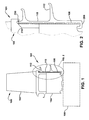
- FIG. 1 shows a cross-sectional view of a relevant portion of a machine 100 including seal assembly 101.
- Machine 100 includes a bucket 102, a wheel 104 and a rotating shaft 106.
- at least one wheel 104 is coupled to rotating shaft 106 of machine 100.
- Each wheel 104 may include a plurality of buckets 102 upon which gas acts to turn rotating shaft 106.
- FIG. 2 shows an enlarged view of a relevant portion of FIG. 1 .
- Seal assembly 101 includes a seal 108, a coverplate 110 and an angel wing 112.
- coverplate 110 fastens to wheel 104 of machine 100 using a hook 206.
- Alternative embodiments for fastening coverplate 110 to wheel 104 may include, for example: a bolt, a pin, a stack or a bayonet retaining ring.
- coverplate 110 can include an outer edge 208 that engages a slot 210 in bucket 102 of machine 100.
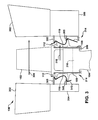
- FIG. 3 shows a cross-sectional view of machine 100 showing gas and air flow movement.
- FIG. 3 shows a nozzle 302 of machine 100.
- nozzle 302 is located on both sides of bucket 102. It is understood, however, that nozzle 302 would be present only on a forward side of bucket 102 where the bucket is a last stage bucket.
- a hot gas flow 308 moves across bucket 102.
- nozzle support ring 304 Immediately below nozzle 302 on the forward (left) or upstream side of machine 100 is a nozzle support ring 304.
- Nozzle 302 includes on both the forward and aft sides, a part 305 that extends from nozzle 302 towards wheel 104.
- a wheelspace 314 exists on the forward and aft side of bucket 102. On the forward side, wheelspace 314 is between nozzle supporting ring 304 and wheel 104. On the aft side, wheelspace 314 is between diaphragm 306 and wheel 104.
- Wheelspace purge air 312 moves through wheelspace 314. Additionally, bucket supply cooling air (not shown) moves from wheel 104 towards bucket 102. An illustration of the movement of wheelspace purge air 312 is shown as it moves through wheelspace 314 and across wheel 104. Coverplate 110 aids in reducing the amount of wheelspace purge air 312 that is able to move between wheel 104 and nozzle support ring 304 on the forward side and wheel 104 and diaphragm 306 on the aft side. Additionally, coverplate 110 aids in the bucket supply cooling air reaching bucket 102 and not entering wheelspace 314. As described above, in one embodiment coverplate 110 and seal 108 can be installed on a forward side or an aft side of wheel 104 ( FIG. 1 ).
- coverplate 110 and seal 108 can be installed on the forward side and the aft side of wheel 104. Additionally, there may be one or more angel wings 112 on coverplate 110. Angel wing 112 may aid in preventing the hot flowpath gas from entering wheelspace 314.
- wheelspace purge air 312 is able to enter perforation 316 in wheel 104.
- coverplate 110 and seal 108 it may reduce or eliminate the amount of wheelspace purge air 312 entering or moving through wheel 104 into wheelspace 314. If no coverplate 110 and seal 108 are installed, wheelspace purge air 310 would be able to move between wheel 104 and wheelspace 314. Coverplate 110 and seal 108 aid in preventing the loss of wheelspace purge air 312.
- bucket supply cooling air may enter wheelspace 314.
- coverplate 110 may be segmented.
- seal 108 may be segmented.
- both coverplate 110 and seal 108 may be segmented.
- seal 108 is positioned to overlap an interface 804 on segment coverplate 806 to eliminate a gap between adjacent circumferentially positioned coverplate segments 802.
- Coverplate 110 and seal 108 can also be used to aid in the secondary flow design of machine 100. Specifically, coverplate 110 and seal 108 can be installed and positioned to aid in the movement of air and gas flow to directed locations. Moreover, coverplate 110 and seal 108 can be installed and positioned to prevent leakages of pressurized air (e.g., wheelspace purge air and bucket supply cooling air) and ingestion of hot gas. Additionally, coverplate 110 and seal 108 can be used as a heat shield for wheel 104 by reducing the amount of hot gas flow 308 that contacts or comes in proximity to wheel 104 or by providing an additional barrier between bucket 102 and wheel 104.
- pressurized air e.g., wheelspace purge air and bucket supply cooling air
- coverplate 110 and seal 108 can be used to dampen vibration on wheel 104 and bucket 102 and for machine 100 as a whole.
- coverplate 110 and seal 108 can provide an additional mechanical connection between wheel 104 and bucket 102.
- the additional connection between bucket 102 and wheel 104 may provide increased rigidity and reduce the vibration while machine 100 is in operation.
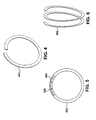
- a 360-degree single coil seal with a single split (“single coil seal”) 402 is shown.
- the single coil seal 402 allows for installation and maintenance, including assembly and disassembly, on machine 100 both at the factory and when machine 100 is at a customer's site.
- the single coil seal 402 allows for the seal to be spread apart allowing for maintenance and repair of machine 100.
- by single coil seal 402 having a break in its circumference it provides the flexibility so that it may be maneuvered on and off of machine 100.
- single coil seal 402 with its single split retains the rigidity and durability where it can perform as described in detail above, and be installed and removed from machine 100.
- single coil seal 502 can be mechanically coupled by, for example, a tongue and groove, a lap joint, a dovetail, a butt joint, a weld or a braze. Additionally, a coverplate 504 can be placed over the joint in the single coil seal 502 when it is mechanically coupled. In one embodiment, a mechanically coupled single coil seal with a coverplate 504 will have the single coil seal 402 positioned on the coverplate 504 to eliminate a gap 506 between adjacent circumferentially positioned coverplate segments 504.
- FIG. 6 illustrates a 720-degree multi coil seal ("multi coil seal") 602.
- the ends of the multi coil seal are not mechanically coupled to one another. This allows for flexibility in the seal during installation and maintenance of machine 100 in addition to installation and removal of multi coil seal 602 on machine 100.
- Other embodiments may include a multi coil seal having more than 720 degrees, if desired.
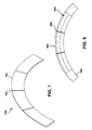
- Segmented seal 700 includes a joint 702 where segments 704 connect.
- a coverplate 110 can be installed over a segmented seal 700.
- FIG. 8 shows a segmented seal 700 with a segmented coverplate 806 over segmented seal 700.
- a coverplate joint 804 can be staggered from joint 702 of segmented seal 700 where the segmented seal 700 is positioned on the coverplate segment 804 to eliminate a gap between adjacent circumferentially positioned coverplate segments.
- FIG. 9 this figure illustrates an alternative embodiment wherein a seal 904 extends along a side of bucket 102 and wheel 104 covering an interface therebetween.
- Seal 904 may attach to bucket 102 by a hook 902 on bucket 102 and seal 904 may attach to wheel 104 by a hook 906 on wheel 104.
- Seal 904 may be on the forward or aft side of wheel 104. In an additional embodiment, seal 904 may be may be on the forward and aft side of wheel 104. Seal 904 may take the form of any of the above-described seals.
Landscapes
- Engineering & Computer Science (AREA)
- Mechanical Engineering (AREA)
- General Engineering & Computer Science (AREA)
- Sealing Using Fluids, Sealing Without Contact, And Removal Of Oil (AREA)
- Structures Of Non-Positive Displacement Pumps (AREA)
- Turbine Rotor Nozzle Sealing (AREA)
Abstract
Description
- The subject matter disclosed herein relates generally to machines and a seal assembly for machines and more specifically to a seal assembly to improve the operation, performance and efficiency of a machine. Machine performance is degraded by the loss of pressurized cooling air and ingestion of hot gas flow.
- Various aspects of the present invention provide a machine and a seal assembly for a machine having a rotating shaft, a wheel coupled to the rotating shaft, the wheel including a bucket coupled to the wheel comprising: a seal that extends along a side of the bucket and the wheel, covering an interface there between.
- A first aspect of the invention provides a machine comprising: a rotating shaft, a wheel coupled to the rotating shaft, the wheel including a bucket coupled to the wheel, and a seal that extends along a side of the bucket and the wheel, covering an interface there between.
- A second aspect of the invention provides a seal assembly for a machine having a rotating shaft, the seal assembly comprising: a wheel coupled to the rotating shaft, the wheel including a bucket coupled to the wheel; and a seal that extends along a side of the bucket and the wheel, covering an interface there between.
- Various features of the disclosure will be more readily understood from the following detailed description of the various aspects of the invention taken in conjunction with the accompanying drawings that depict various aspects of the invention, in which:
-
FIG. 1 shows a cross-sectional view of a bucket and wheel from a machine. -
FIG. 2 shows a cross-sectional view of a bucket and wheel from a machine with an enlarged view from an area ofFIG. 1 illustrating a coverplate and seal. -
FIG. 3 shows a cross-sectional view of a machine showing gas and air flow movement. -
FIG. 4 shows a 360-degree single coil seal with a single split. -
FIG. 5 shows a 360-degree single coil seal with a single split wherein the ends of the split are mechanically coupled and there is a segmented coverplate over the mechanically coupled ends of the single coil seal. -
FIG. 6 shows a 720-degree multi-coil seal. -
FIG. 7 shows a portion of a segmented seal. -
FIG. 8 shows a portion of a segmented seal with a segmented coverplate over the segmented seal. -
FIG. 9 shows a cross sectional view of a bucket and wheel from a machine. - It is noted that the drawings are not to scale. The drawings are intended to depict only typical aspects of the invention, and therefore should not be considered as limiting the scope of the invention. In the drawings, like numbering represents like elements between the drawings.
- As indicated above, aspects of the invention provide improved operation, performance and efficiency of a machine. As used throughout this application, reference to machine is to include: a gas turbine, a steam turbine or a compressor. In one embodiment, the invention discussed herein includes a coverplate that is fastened to a wheel and bucket of a machine and a seal positioned between the coverplate and the wheel and the bucket. One feature of the coverplate and seal on the machine is that it reduces the loss of pressurized air from the system. Additionally, the coverplate and seal may prevent the inflow of hot gas into the wheelspace and aid in the secondary air flow of the machine. Moreover, the coverplate and seal discussed herein may facilitate maintenance on the machine. Furthermore, the coverplate and seal may facilitate assembly and disassembly of the machine as the coverplate and seal can be installed and removed while the rotating shaft is on the half shell. The coverplate and seal may also improve the machine's performance by acting as a heat shield and reduce vibration through the addition of damping. The coverplate and seal can be installed on a forward side or an aft side of the wheel. Alternatively, the coverplate and seal can be installed on the forward side and the aft side of the wheel.
- Turning to the drawings,
FIG. 1 shows a cross-sectional view of a relevant portion of amachine 100 includingseal assembly 101.Machine 100 includes abucket 102, awheel 104 and a rotatingshaft 106. As understood, at least onewheel 104 is coupled to rotatingshaft 106 ofmachine 100. Eachwheel 104 may include a plurality ofbuckets 102 upon which gas acts to turn rotatingshaft 106. -
FIG. 2 shows an enlarged view of a relevant portion ofFIG. 1 .Seal assembly 101 includes aseal 108, acoverplate 110 and anangel wing 112. In one embodiment,coverplate 110 fastens towheel 104 ofmachine 100 using ahook 206. Alternative embodiments for fasteningcoverplate 110 towheel 104 may include, for example: a bolt, a pin, a stack or a bayonet retaining ring. In another embodiment,coverplate 110 can include anouter edge 208 that engages aslot 210 inbucket 102 ofmachine 100. -
FIG. 3 shows a cross-sectional view ofmachine 100 showing gas and air flow movement.FIG. 3 shows anozzle 302 ofmachine 100. As illustrated,nozzle 302 is located on both sides ofbucket 102. It is understood, however, thatnozzle 302 would be present only on a forward side ofbucket 102 where the bucket is a last stage bucket. Ahot gas flow 308 moves acrossbucket 102. Immediately belownozzle 302 on the forward (left) or upstream side ofmachine 100 is anozzle support ring 304. Immediately belownozzle 302 on the aft (right) or downstream side ofmachine 100 is adiaphragm 306.Nozzle 302 includes on both the forward and aft sides, apart 305 that extends fromnozzle 302 towardswheel 104. Awheelspace 314 exists on the forward and aft side ofbucket 102. On the forward side,wheelspace 314 is betweennozzle supporting ring 304 andwheel 104. On the aft side,wheelspace 314 is betweendiaphragm 306 andwheel 104. -
Wheelspace purge air 312 moves throughwheelspace 314. Additionally, bucket supply cooling air (not shown) moves fromwheel 104 towardsbucket 102. An illustration of the movement ofwheelspace purge air 312 is shown as it moves throughwheelspace 314 and acrosswheel 104. Coverplate 110 aids in reducing the amount ofwheelspace purge air 312 that is able to move betweenwheel 104 andnozzle support ring 304 on the forward side andwheel 104 anddiaphragm 306 on the aft side. Additionally, coverplate 110 aids in the bucket supply coolingair reaching bucket 102 and not enteringwheelspace 314. As described above, in oneembodiment coverplate 110 andseal 108 can be installed on a forward side or an aft side of wheel 104 (FIG. 1 ). In another embodiment,coverplate 110 andseal 108 can be installed on the forward side and the aft side ofwheel 104. Additionally, there may be one ormore angel wings 112 oncoverplate 110. Angelwing 112 may aid in preventing the hot flowpath gas from enteringwheelspace 314. - When there is no
coverplate 110 andseal 108 present,wheelspace purge air 312 is able to enterperforation 316 inwheel 104. Whencoverplate 110 andseal 108 are present, it may reduce or eliminate the amount ofwheelspace purge air 312 entering or moving throughwheel 104 intowheelspace 314. If nocoverplate 110 andseal 108 are installed,wheelspace purge air 310 would be able to move betweenwheel 104 andwheelspace 314.Coverplate 110 and seal 108 aid in preventing the loss ofwheelspace purge air 312. Moreover, when there is nocoverplate 110 andseal 108 present, bucket supply cooling air may enterwheelspace 314. - In one embodiment,
coverplate 110 may be segmented. In another embodiment,seal 108 may be segmented. In a further embodiment, bothcoverplate 110 andseal 108 may be segmented. In an alternative embodiment, shown inFIG. 8 , where there is asegmented coverplate 806 and asegmented seal 700 or eithersegmented coverplate 806 orsegmented seal 700,seal 108 is positioned to overlap aninterface 804 onsegment coverplate 806 to eliminate a gap between adjacent circumferentially positionedcoverplate segments 802. -
Coverplate 110 and seal 108 can also be used to aid in the secondary flow design ofmachine 100. Specifically,coverplate 110 and seal 108 can be installed and positioned to aid in the movement of air and gas flow to directed locations. Moreover,coverplate 110 and seal 108 can be installed and positioned to prevent leakages of pressurized air (e.g., wheelspace purge air and bucket supply cooling air) and ingestion of hot gas. Additionally,coverplate 110 and seal 108 can be used as a heat shield forwheel 104 by reducing the amount ofhot gas flow 308 that contacts or comes in proximity towheel 104 or by providing an additional barrier betweenbucket 102 andwheel 104. In a further embodiment,coverplate 110 and seal 108 can be used to dampen vibration onwheel 104 andbucket 102 and formachine 100 as a whole. For example,coverplate 110 and seal 108 can provide an additional mechanical connection betweenwheel 104 andbucket 102. The additional connection betweenbucket 102 andwheel 104 may provide increased rigidity and reduce the vibration whilemachine 100 is in operation. - Turning to
FIG. 4 , a 360-degree single coil seal with a single split ("single coil seal") 402 is shown. Thesingle coil seal 402 allows for installation and maintenance, including assembly and disassembly, onmachine 100 both at the factory and whenmachine 100 is at a customer's site. In one embodiment, thesingle coil seal 402 allows for the seal to be spread apart allowing for maintenance and repair ofmachine 100. In a further embodiment, bysingle coil seal 402 having a break in its circumference, it provides the flexibility so that it may be maneuvered on and off ofmachine 100. In another embodiment,single coil seal 402 with its single split retains the rigidity and durability where it can perform as described in detail above, and be installed and removed frommachine 100. - Turning to
FIG. 5 , and with continuing reference toFIG. 4 , the ends ofsingle coil seal 502 can be mechanically coupled by, for example, a tongue and groove, a lap joint, a dovetail, a butt joint, a weld or a braze. Additionally, acoverplate 504 can be placed over the joint in thesingle coil seal 502 when it is mechanically coupled. In one embodiment, a mechanically coupled single coil seal with acoverplate 504 will have thesingle coil seal 402 positioned on thecoverplate 504 to eliminate agap 506 between adjacent circumferentially positionedcoverplate segments 504. -
FIG. 6 illustrates a 720-degree multi coil seal ("multi coil seal") 602. In one embodiment, the ends of the multi coil seal are not mechanically coupled to one another. This allows for flexibility in the seal during installation and maintenance ofmachine 100 in addition to installation and removal ofmulti coil seal 602 onmachine 100. Other embodiments may include a multi coil seal having more than 720 degrees, if desired. - Turning to
FIG. 7 , a portion of asegmented seal 700 is illustrated.Segmented seal 700 includes a joint 702 wheresegments 704 connect. In one embodiment, acoverplate 110 can be installed over asegmented seal 700.FIG. 8 shows asegmented seal 700 with asegmented coverplate 806 oversegmented seal 700. ExaminingFIG. 8 , with continuing reference toFIG. 7 , in one embodiment a coverplate joint 804 can be staggered from joint 702 ofsegmented seal 700 where thesegmented seal 700 is positioned on thecoverplate segment 804 to eliminate a gap between adjacent circumferentially positioned coverplate segments. - Turning to
FIG. 9 , this figure illustrates an alternative embodiment wherein aseal 904 extends along a side ofbucket 102 andwheel 104 covering an interface therebetween.Seal 904 may attach tobucket 102 by ahook 902 onbucket 102 and seal 904 may attach towheel 104 by ahook 906 onwheel 104.Seal 904 may be on the forward or aft side ofwheel 104. In an additional embodiment, seal 904 may be may be on the forward and aft side ofwheel 104.Seal 904 may take the form of any of the above-described seals. - While various embodiments are described herein, it will be appreciated from the specification that various combinations of elements, variations or improvements therein may be made by those skilled in the art, and are within the scope of the invention. In addition, many modifications may be made to adapt a particular situation or material to the teachings of the invention without departing from essential scope thereof. Therefore, it is intended that the invention not be limited to the particular embodiment disclosed as the preferred mode contemplated for carrying out this invention, but that the invention will include all embodiments falling within the scope of the appended claims.
- Various aspects and embodiments of the present invention are defined by the following numbered clauses:
- 1. A machine comprising:
- a rotating shaft;
- a wheel coupled to the rotating shaft;
- a bucket coupled to the wheel; and
- a seal that extends along a side of the bucket and the wheel, covering an interface therebetween.
- 2. The machine of
clause 1, wherein the bucket includes a hook for fastening the seal to the bucket of the machine. - 3. The machine of any preceding clause, wherein the wheel includes a hook for fastening the seal to the wheel of the machine.
- 4. The machine of any preceding clause, wherein the seal includes a 360-degree seal with a single split.
- 5. The machine of any preceding clause, wherein the seal includes a 720-degree multi-coil seal.
- 6. The machine of any preceding clause, wherein the seal includes a segmented seal.
- 7. The machine of any preceding clause, wherein the seal is installed on a forward side of the wheel.
- 8. The machine of any preceding clause, wherein the seal is installed on an aft side of the wheel.
- 9. The machine of any preceding clause, wherein the seal is installed on the forward side and the aft side of the wheel.
- 10. A seal assembly for a machine having a rotating shaft, the seal assembly comprising:
- a wheel coupled to the rotating shaft;
- a bucket coupled to the wheel; and
- a seal that extends along a side of the bucket and the wheel, covering an interface therebetween.
- 11. The seal assembly of any preceding clause, wherein the bucket includes a hook for fastening the seal to the bucket of the machine.
- 12. The seal assembly of any preceding clause, wherein the wheel includes a hook for fastening the seal to the wheel of the machine.
- 13. The seal assembly of any preceding clause, wherein the seal includes a 360-degree seal with a single split.
- 14. The seal assembly of any preceding clause, wherein the seal includes a 720-degree multi-coil seal.
- 15. The seal assembly of any preceding clause, wherein the seal includes a segmented seal.
- 16. The seal assembly of any preceding clause, wherein the seal is installed on a forward side of the wheel.
- 17. The seal assembly of any preceding clause, wherein the seal is installed on an aft side of the wheel.
- 18. The seal assembly of any preceding clause, wherein the seal is installed on the forward side and the aft side of the wheel.
Claims (15)
- A machine (100) comprising:a rotating shaft (106);a wheel (104) coupled to the rotating shaft (106);a bucket (102) coupled to the wheel (104); anda seal (108, 904) that extends along a side of the bucket (102) and the wheel (104), covering an interface (804) therebetween.
- The machine of claim 1, wherein the bucket (102) includes a hook (206, 902, 906) for fastening the seal (108, 904) to the bucket (102) of the machine (100).
- The machine of any preceding claim, wherein the wheel (104) includes a hook (206, 902, 906) for fastening the seal (108, 904) to the wheel (104) of the machine (100).
- The machine of any preceding claim, wherein the seal (108, 904) includes a 360-degree seal (108, 904) with a single split.
- The machine of any preceding claim, wherein the seal (108, 904) includes a 720-degree multi-coil seal.
- The machine of any preceding claim, wherein the seal (108, 904) includes a segmented seal.
- The machine of any preceding claim, wherein the seal (108, 904) is installed on a forward side of the wheel (104).
- The machine of any preceding claim, wherein the seal (108, 904) is installed on an aft side of the wheel (104).
- The machine of any preceding claim, wherein the seal (108, 904) is installed on the forward side and the aft side of the wheel (104).
- A seal (108, 904) assembly (101) for a machine (100) having a rotating shaft (106), the seal (108, 904) assembly (101) comprising:a wheel (104) coupled to the rotating shaft (106);a bucket (102) coupled to the wheel (104); anda seal (108, 904) that extends along a side of the bucket (102) and the wheel (104), covering an interface (804) therebetween.
- The seal assembly of claim 10, wherein the bucket (102) includes a hook (206, 902, 906) for fastening the seal (108, 904) to the bucket (102) of the machine (100).
- The seal assembly of claim 10 or claim 11, wherein the wheel (104) includes a hook (206, 902, 906) for fastening the seal (108, 904) to the wheel (104) of the machine (100).
- The seal assembly of any of claims 10 to 12, wherein the seal (108, 904) includes a 360-degree seal (108, 904) with a single split.
- The seal assembly of any of claims 10 to 13, wherein the seal (108, 904) includes a 720-degree multi-coil seal.
- The seal assembly of any of claims 10 to 14, wherein the seal (108, 904) includes a segmented seal.
Applications Claiming Priority (1)
| Application Number | Priority Date | Filing Date | Title |
|---|---|---|---|
| US12/402,808 US20100232939A1 (en) | 2009-03-12 | 2009-03-12 | Machine Seal Assembly |
Publications (2)
| Publication Number | Publication Date |
|---|---|
| EP2236768A2 true EP2236768A2 (en) | 2010-10-06 |
| EP2236768A3 EP2236768A3 (en) | 2014-12-24 |
Family
ID=42337449
Family Applications (1)
| Application Number | Title | Priority Date | Filing Date |
|---|---|---|---|
| EP10155312.1A Withdrawn EP2236768A3 (en) | 2009-03-12 | 2010-03-03 | Turbomachine seal assembly |
Country Status (4)
| Country | Link |
|---|---|
| US (1) | US20100232939A1 (en) |
| EP (1) | EP2236768A3 (en) |
| JP (1) | JP5475511B2 (en) |
| CN (1) | CN101893001A (en) |
Cited By (5)
| Publication number | Priority date | Publication date | Assignee | Title |
|---|---|---|---|---|
| EP2586988A1 (en) * | 2011-10-26 | 2013-05-01 | General Electric Company | Turbine cover plate assembly |
| FR2999641A1 (en) * | 2012-12-17 | 2014-06-20 | Snecma | Turbine engine stage for e.g. turbopropeller of airplane, has annular flask fixed at internal periphery of distributer and comprising annular parts surrounding upstream cylindrical spoiler of wheel |
| EP2949873A1 (en) * | 2014-05-27 | 2015-12-02 | Siemens Aktiengesellschaft | Turbomachine with an ingestion shield and use of the turbomachine |
| US10851661B2 (en) | 2017-08-01 | 2020-12-01 | General Electric Company | Sealing system for a rotary machine and method of assembling same |
| EP3757473A1 (en) * | 2019-06-24 | 2020-12-30 | FläktGroup Sweden AB | Method for forming a seal between ventilation ducts and/or their terminal units, and seal |
Families Citing this family (7)
| Publication number | Priority date | Publication date | Assignee | Title |
|---|---|---|---|---|
| US8277172B2 (en) * | 2009-03-23 | 2012-10-02 | General Electric Company | Apparatus for turbine engine cooling air management |
| US8142141B2 (en) * | 2009-03-23 | 2012-03-27 | General Electric Company | Apparatus for turbine engine cooling air management |
| US8845284B2 (en) | 2010-07-02 | 2014-09-30 | General Electric Company | Apparatus and system for sealing a turbine rotor |
| US20130094969A1 (en) * | 2011-10-17 | 2013-04-18 | General Electric Company | System for sealing a shaft |
| US8864453B2 (en) | 2012-01-20 | 2014-10-21 | General Electric Company | Near flow path seal for a turbomachine |
| US9080456B2 (en) | 2012-01-20 | 2015-07-14 | General Electric Company | Near flow path seal with axially flexible arms |
| US10161257B2 (en) * | 2015-10-20 | 2018-12-25 | General Electric Company | Turbine slotted arcuate leaf seal |
Family Cites Families (67)
| Publication number | Priority date | Publication date | Assignee | Title |
|---|---|---|---|---|
| US3043562A (en) * | 1961-04-10 | 1962-07-10 | Gen Electric | Combination sealing and restraining member for long-shank turbo-machine buckets |
| NL295165A (en) * | 1962-07-11 | |||
| US3501249A (en) * | 1968-06-24 | 1970-03-17 | Westinghouse Electric Corp | Side plates for turbine blades |
| GB1291302A (en) * | 1970-03-14 | 1972-10-04 | Sec Dep For Defendence | Improvements in bladed rotor assemblies |
| BE791375A (en) * | 1971-12-02 | 1973-03-01 | Gen Electric | DEFLECTOR AND SHOCK ABSORBER FOR TURBOMACHINE FINS |
| BE792286A (en) * | 1971-12-06 | 1973-03-30 | Gen Electric | BOLTLESS AUBA RETAINER FOR TURBOMACHIN ROTOR |
| US3814539A (en) * | 1972-10-04 | 1974-06-04 | Gen Electric | Rotor sealing arrangement for an axial flow fluid turbine |
| US3829233A (en) * | 1973-06-27 | 1974-08-13 | Westinghouse Electric Corp | Turbine diaphragm seal structure |
| US3853425A (en) * | 1973-09-07 | 1974-12-10 | Westinghouse Electric Corp | Turbine rotor blade cooling and sealing system |
| GB1479332A (en) * | 1974-11-06 | 1977-07-13 | Rolls Royce | Means for retaining blades to a disc or like structure |
| US4021138A (en) * | 1975-11-03 | 1977-05-03 | Westinghouse Electric Corporation | Rotor disk, blade, and seal plate assembly for cooled turbine rotor blades |
| US4088421A (en) * | 1976-09-30 | 1978-05-09 | General Electric Company | Coverplate damping arrangement |
| US4218189A (en) * | 1977-08-09 | 1980-08-19 | Rolls-Royce Limited | Sealing means for bladed rotor for a gas turbine engine |
| CH626947A5 (en) * | 1978-03-02 | 1981-12-15 | Bbc Brown Boveri & Cie | |
| US4326835A (en) * | 1979-10-29 | 1982-04-27 | General Motors Corporation | Blade platform seal for ceramic/metal rotor assembly |
| US4480958A (en) * | 1983-02-09 | 1984-11-06 | The United States Of America As Represented By The Secretary Of The Air Force | High pressure turbine rotor two-piece blade retainer |
| US4507052A (en) * | 1983-03-31 | 1985-03-26 | General Motors Corporation | End seal for turbine blade bases |
| US4523890A (en) * | 1983-10-19 | 1985-06-18 | General Motors Corporation | End seal for turbine blade base |
| US4500098A (en) * | 1983-12-22 | 1985-02-19 | United Technologies Corporation | Gas seal for rotating components |
| US4659285A (en) * | 1984-07-23 | 1987-04-21 | United Technologies Corporation | Turbine cover-seal assembly |
| US4645424A (en) * | 1984-07-23 | 1987-02-24 | United Technologies Corporation | Rotating seal for gas turbine engine |
| US4659289A (en) * | 1984-07-23 | 1987-04-21 | United Technologies Corporation | Turbine side plate assembly |
| JPS61205303A (en) * | 1985-03-06 | 1986-09-11 | Mitsubishi Heavy Ind Ltd | Stopper in axial direction for turbine moving blade |
| US4743164A (en) * | 1986-12-29 | 1988-05-10 | United Technologies Corporation | Interblade seal for turbomachine rotor |
| US4781534A (en) * | 1987-02-27 | 1988-11-01 | Westinghouse Electric Corp. | Apparatus and method for reducing windage and leakage in steam turbine incorporating axial entry blade |
| JPH0723524Y2 (en) * | 1988-03-29 | 1995-05-31 | 川崎重工業株式会社 | Axial turbine |
| GB2251040B (en) * | 1990-12-22 | 1994-06-22 | Rolls Royce Plc | Seal arrangement |
| US5275534A (en) * | 1991-10-30 | 1994-01-04 | General Electric Company | Turbine disk forward seal assembly |
| US5236302A (en) * | 1991-10-30 | 1993-08-17 | General Electric Company | Turbine disk interstage seal system |
| US5277548A (en) * | 1991-12-31 | 1994-01-11 | United Technologies Corporation | Non-integral rotor blade platform |
| US5257909A (en) * | 1992-08-17 | 1993-11-02 | General Electric Company | Dovetail sealing device for axial dovetail rotor blades |
| US5338154A (en) * | 1993-03-17 | 1994-08-16 | General Electric Company | Turbine disk interstage seal axial retaining ring |
| US5503528A (en) * | 1993-12-27 | 1996-04-02 | Solar Turbines Incorporated | Rim seal for turbine wheel |
| US5429478A (en) * | 1994-03-31 | 1995-07-04 | United Technologies Corporation | Airfoil having a seal and an integral heat shield |
| KR100364183B1 (en) * | 1994-10-31 | 2003-02-19 | 웨스팅하우스 일렉트릭 코포레이션 | Gas turbine blade with a cooled platform |
| GB2317652B (en) * | 1996-09-26 | 2000-05-17 | Rolls Royce Plc | Seal arrangement |
| US5803710A (en) * | 1996-12-24 | 1998-09-08 | United Technologies Corporation | Turbine engine rotor blade platform sealing and vibration damping device |
| JP3462695B2 (en) * | 1997-03-12 | 2003-11-05 | 三菱重工業株式会社 | Gas turbine blade seal plate |
| JPH10252412A (en) * | 1997-03-12 | 1998-09-22 | Mitsubishi Heavy Ind Ltd | Gas turbine sealing device |
| JPH10259703A (en) * | 1997-03-18 | 1998-09-29 | Mitsubishi Heavy Ind Ltd | Shroud for gas turbine and platform seal system |
| GB2332024B (en) * | 1997-12-03 | 2000-12-13 | Rolls Royce Plc | Rotary assembly |
| US5993160A (en) * | 1997-12-11 | 1999-11-30 | Pratt & Whitney Canada Inc. | Cover plate for gas turbine rotor |
| US6220814B1 (en) * | 1998-07-16 | 2001-04-24 | Siemens Westinghouse Power Corporation | Turbine interstage sealing arrangement |
| US6273683B1 (en) * | 1999-02-05 | 2001-08-14 | Siemens Westinghouse Power Corporation | Turbine blade platform seal |
| US6561764B1 (en) * | 1999-03-19 | 2003-05-13 | Siemens Aktiengesellschaft | Gas turbine rotor with an internally cooled gas turbine blade and connecting configuration including an insert strip bridging adjacent blade platforms |
| US6190131B1 (en) * | 1999-08-31 | 2001-02-20 | General Electric Co. | Non-integral balanced coverplate and coverplate centering slot for a turbine |
| US6315298B1 (en) * | 1999-11-22 | 2001-11-13 | United Technologies Corporation | Turbine disk and blade assembly seal |
| FR2817290B1 (en) * | 2000-11-30 | 2003-02-21 | Snecma Moteurs | ROTOR BLADE DISC FLANGE AND CORRESPONDING ARRANGEMENT |
| US6506016B1 (en) * | 2001-11-15 | 2003-01-14 | General Electric Company | Angel wing seals for blades of a gas turbine and methods for determining angel wing seal profiles |
| US6669443B2 (en) * | 2001-11-16 | 2003-12-30 | General Electric Company | Rotor platform modification and methods using brush seals in diaphragm packing area of steam turbines to eliminate rotor bowing |
| GB0219781D0 (en) * | 2002-08-23 | 2002-10-02 | Rolls Royce Plc | Seals and a method of making seals |
| US6884028B2 (en) * | 2002-09-30 | 2005-04-26 | General Electric Company | Turbomachinery blade retention system |
| US6779972B2 (en) * | 2002-10-31 | 2004-08-24 | General Electric Company | Flowpath sealing and streamlining configuration for a turbine |
| US6945749B2 (en) * | 2003-09-12 | 2005-09-20 | Siemens Westinghouse Power Corporation | Turbine blade platform cooling system |
| JP3864157B2 (en) * | 2003-12-05 | 2006-12-27 | 本田技研工業株式会社 | Axial turbine wheel |
| GB0412476D0 (en) * | 2004-06-04 | 2004-07-07 | Rolls Royce Plc | Seal system |
| JP2006009576A (en) * | 2004-06-22 | 2006-01-12 | Matsushita Electric Ind Co Ltd | Scroll compressor |
| US7121800B2 (en) * | 2004-09-13 | 2006-10-17 | United Technologies Corporation | Turbine blade nested seal damper assembly |
| US7264448B2 (en) * | 2004-10-06 | 2007-09-04 | Siemens Power Corporation, Inc. | Remotely accessible locking system for turbine blades |
| JP2006266454A (en) * | 2005-03-25 | 2006-10-05 | Matsumura Koki Kk | Ring and sealing structure |
| US7189055B2 (en) * | 2005-05-31 | 2007-03-13 | Pratt & Whitney Canada Corp. | Coverplate deflectors for redirecting a fluid flow |
| JP4035140B2 (en) * | 2005-07-22 | 2008-01-16 | 川崎重工業株式会社 | Turbine rotor seal ring |
| US7465152B2 (en) * | 2005-09-16 | 2008-12-16 | General Electric Company | Angel wing seals for turbine blades and methods for selecting stator, rotor and wing seal profiles |
| US7484936B2 (en) * | 2005-09-26 | 2009-02-03 | Pratt & Whitney Canada Corp. | Blades for a gas turbine engine with integrated sealing plate and method |
| US20070114727A1 (en) * | 2005-11-21 | 2007-05-24 | General Electric Company | Seal member, assembly and method |
| DE602006006452D1 (en) * | 2006-09-25 | 2009-06-04 | Siemens Ag | Turbine rotor with closure plates and corresponding assembly process |
| US8206119B2 (en) * | 2009-02-05 | 2012-06-26 | General Electric Company | Turbine coverplate systems |
-
2009
- 2009-03-12 US US12/402,808 patent/US20100232939A1/en not_active Abandoned
-
2010
- 2010-03-03 EP EP10155312.1A patent/EP2236768A3/en not_active Withdrawn
- 2010-03-10 JP JP2010052474A patent/JP5475511B2/en not_active Expired - Fee Related
- 2010-03-12 CN CN2010101468881A patent/CN101893001A/en active Pending
Non-Patent Citations (1)
| Title |
|---|
| None |
Cited By (8)
| Publication number | Priority date | Publication date | Assignee | Title |
|---|---|---|---|---|
| EP2586988A1 (en) * | 2011-10-26 | 2013-05-01 | General Electric Company | Turbine cover plate assembly |
| US9217334B2 (en) | 2011-10-26 | 2015-12-22 | General Electric Company | Turbine cover plate assembly |
| FR2999641A1 (en) * | 2012-12-17 | 2014-06-20 | Snecma | Turbine engine stage for e.g. turbopropeller of airplane, has annular flask fixed at internal periphery of distributer and comprising annular parts surrounding upstream cylindrical spoiler of wheel |
| EP2949873A1 (en) * | 2014-05-27 | 2015-12-02 | Siemens Aktiengesellschaft | Turbomachine with an ingestion shield and use of the turbomachine |
| WO2015180946A1 (en) * | 2014-05-27 | 2015-12-03 | Siemens Aktiengesellschaft | Turbomachine with an ingestion shield and use of the turbomachine |
| US10337344B2 (en) | 2014-05-27 | 2019-07-02 | Siemens Aktiengesellschaft | Turbomachine with an ingestion shield and use of the turbomachine |
| US10851661B2 (en) | 2017-08-01 | 2020-12-01 | General Electric Company | Sealing system for a rotary machine and method of assembling same |
| EP3757473A1 (en) * | 2019-06-24 | 2020-12-30 | FläktGroup Sweden AB | Method for forming a seal between ventilation ducts and/or their terminal units, and seal |
Also Published As
| Publication number | Publication date |
|---|---|
| JP5475511B2 (en) | 2014-04-16 |
| CN101893001A (en) | 2010-11-24 |
| EP2236768A3 (en) | 2014-12-24 |
| US20100232939A1 (en) | 2010-09-16 |
| JP2010216657A (en) | 2010-09-30 |
Similar Documents
| Publication | Publication Date | Title |
|---|---|---|
| US8696320B2 (en) | Gas turbine having seal assembly with coverplate and seal | |
| EP2236768A2 (en) | Turbomachine seal assembly | |
| CN106948867B (en) | Turbine rotor blades with shrouds | |
| CN106917643B (en) | Turbine rotor blades with shrouds | |
| US9169736B2 (en) | Joint between airfoil and shroud | |
| US9797262B2 (en) | Split damped outer shroud for gas turbine engine stator arrays | |
| EP2562355B1 (en) | Array of rotor blades and method of installing rotor blades | |
| CA2552214C (en) | Blades for a gas turbine engine with integrated sealing plate and method | |
| US8371816B2 (en) | Rotor blades for turbine engines | |
| EP2620591B1 (en) | Gas turbine engine stator vane assembly with inner shroud | |
| US20140255194A1 (en) | Tip shrouds of turbine rotor blades and methods of manufacture related thereto | |
| EP2660427B1 (en) | Turbine system comprising a transition duct with a convolution seal | |
| US20110274541A1 (en) | Annular flange for fastening a rotor or stator element in a turbomachine | |
| EP2612996A1 (en) | Device and method for aligning tip shrouds | |
| EP2415969A1 (en) | Component of a turbine with leaf seals and method for sealing against leakage between a vane and a carrier element | |
| US20100068041A1 (en) | Shroud for a turbomachine | |
| US11193392B2 (en) | CMC ply overlap ingestion restrictor | |
| US20150176413A1 (en) | Snubber configurations for turbine rotor blades | |
| EP3189215B1 (en) | A transition-to-turbine seal assembly | |
| CN104011333B (en) | Turboset compressor guide vane assembly | |
| EP2971615B1 (en) | Low leakage duct segment using expansion joint assembly | |
| EP3336318A1 (en) | Struts for exhaust frames of turbine systems | |
| EP3228828A1 (en) | Integrated brush seals | |
| US20090206554A1 (en) | Steam turbine engine and method of assembling same | |
| US10072514B2 (en) | Method and apparatus for attaching a transition duct to a turbine section in a gas turbine engine |
Legal Events
| Date | Code | Title | Description |
|---|---|---|---|
| PUAI | Public reference made under article 153(3) epc to a published international application that has entered the european phase |
Free format text: ORIGINAL CODE: 0009012 |
|
| AK | Designated contracting states |
Kind code of ref document: A2 Designated state(s): AT BE BG CH CY CZ DE DK EE ES FI FR GB GR HR HU IE IS IT LI LT LU LV MC MK MT NL NO PL PT RO SE SI SK SM TR |
|
| AX | Request for extension of the european patent |
Extension state: AL BA ME RS |
|
| PUAL | Search report despatched |
Free format text: ORIGINAL CODE: 0009013 |
|
| AK | Designated contracting states |
Kind code of ref document: A3 Designated state(s): AT BE BG CH CY CZ DE DK EE ES FI FR GB GR HR HU IE IS IT LI LT LU LV MC MK MT NL NO PL PT RO SE SI SK SM TR |
|
| AX | Request for extension of the european patent |
Extension state: AL BA ME RS |
|
| RIC1 | Information provided on ipc code assigned before grant |
Ipc: F01D 11/00 20060101AFI20141118BHEP |
|
| STAA | Information on the status of an ep patent application or granted ep patent |
Free format text: STATUS: THE APPLICATION IS DEEMED TO BE WITHDRAWN |
|
| 18D | Application deemed to be withdrawn |
Effective date: 20150625 |