EP2236748B1 - A rotor arrangement for a gas turbine - Google Patents
A rotor arrangement for a gas turbine Download PDFInfo
- Publication number
- EP2236748B1 EP2236748B1 EP10250348.9A EP10250348A EP2236748B1 EP 2236748 B1 EP2236748 B1 EP 2236748B1 EP 10250348 A EP10250348 A EP 10250348A EP 2236748 B1 EP2236748 B1 EP 2236748B1
- Authority
- EP
- European Patent Office
- Prior art keywords
- arrangement
- slot
- outlet
- collector
- return
- Prior art date
- Legal status (The legal status is an assumption and is not a legal conclusion. Google has not performed a legal analysis and makes no representation as to the accuracy of the status listed.)
- Not-in-force
Links
- 230000008878 coupling Effects 0.000 claims description 5
- 238000010168 coupling process Methods 0.000 claims description 5
- 238000005859 coupling reaction Methods 0.000 claims description 5
- 241001272720 Medialuna californiensis Species 0.000 claims description 4
- 230000001419 dependent effect Effects 0.000 claims 1
- 239000012530 fluid Substances 0.000 abstract description 16
- 238000010408 sweeping Methods 0.000 abstract description 5
- 230000000694 effects Effects 0.000 abstract description 3
- 238000006073 displacement reaction Methods 0.000 description 3
- 230000001141 propulsive effect Effects 0.000 description 3
- 230000004075 alteration Effects 0.000 description 1
- 238000002485 combustion reaction Methods 0.000 description 1
- 230000006835 compression Effects 0.000 description 1
- 238000007906 compression Methods 0.000 description 1
- 230000001627 detrimental effect Effects 0.000 description 1
- 230000003467 diminishing effect Effects 0.000 description 1
- 239000000446 fuel Substances 0.000 description 1
- 239000000203 mixture Substances 0.000 description 1
- 230000004048 modification Effects 0.000 description 1
- 238000012986 modification Methods 0.000 description 1
- 230000001151 other effect Effects 0.000 description 1
- 238000007493 shaping process Methods 0.000 description 1
- 238000004513 sizing Methods 0.000 description 1
- 238000011144 upstream manufacturing Methods 0.000 description 1
Images

Classifications
-
- F—MECHANICAL ENGINEERING; LIGHTING; HEATING; WEAPONS; BLASTING
- F01—MACHINES OR ENGINES IN GENERAL; ENGINE PLANTS IN GENERAL; STEAM ENGINES
- F01D—NON-POSITIVE DISPLACEMENT MACHINES OR ENGINES, e.g. STEAM TURBINES
- F01D5/00—Blades; Blade-carrying members; Heating, heat-insulating, cooling or antivibration means on the blades or the members
- F01D5/12—Blades
- F01D5/14—Form or construction
- F01D5/141—Shape, i.e. outer, aerodynamic form
- F01D5/145—Means for influencing boundary layers or secondary circulations
-
- F—MECHANICAL ENGINEERING; LIGHTING; HEATING; WEAPONS; BLASTING
- F05—INDEXING SCHEMES RELATING TO ENGINES OR PUMPS IN VARIOUS SUBCLASSES OF CLASSES F01-F04
- F05D—INDEXING SCHEME FOR ASPECTS RELATING TO NON-POSITIVE-DISPLACEMENT MACHINES OR ENGINES, GAS-TURBINES OR JET-PROPULSION PLANTS
- F05D2250/00—Geometry
- F05D2250/30—Arrangement of components
- F05D2250/31—Arrangement of components according to the direction of their main axis or their axis of rotation
- F05D2250/314—Arrangement of components according to the direction of their main axis or their axis of rotation the axes being inclined in relation to each other
-
- Y—GENERAL TAGGING OF NEW TECHNOLOGICAL DEVELOPMENTS; GENERAL TAGGING OF CROSS-SECTIONAL TECHNOLOGIES SPANNING OVER SEVERAL SECTIONS OF THE IPC; TECHNICAL SUBJECTS COVERED BY FORMER USPC CROSS-REFERENCE ART COLLECTIONS [XRACs] AND DIGESTS
- Y02—TECHNOLOGIES OR APPLICATIONS FOR MITIGATION OR ADAPTATION AGAINST CLIMATE CHANGE
- Y02T—CLIMATE CHANGE MITIGATION TECHNOLOGIES RELATED TO TRANSPORTATION
- Y02T50/00—Aeronautics or air transport
- Y02T50/60—Efficient propulsion technologies, e.g. for aircraft
Definitions
- the present invention relates to rotor arrangements and more particularly rotor arrangements utilised in gas turbine engines in the region of rotor hubs and stator shrouds.
- a gas turbine engine is generally indicated at 10 and comprises, in axial flow series, an air intake 11, a propulsive fan 12, an intermediate pressure compressor 13, a high pressure compressor 14, a combustor 15, a turbine arrangement comprising a high pressure turbine 16, an intermediate pressure turbine 17 and a low pressure turbine 18, and an exhaust nozzle 19.
- the gas turbine engine 10 operates in a conventional manner so that air entering the intake 11 is accelerated by the fan 12 which produce two air flows: a first air flow into the intermediate pressure compressor 13 and a second air flow which provides propulsive thrust.
- the intermediate pressure compressor compresses the air flow directed into it before delivering that air to the high pressure compressor 14 where further compression takes place.
- the compressed air exhausted from the high pressure compressor 14 is directed into the combustor 15 where it is mixed with fuel and the mixture combusted.
- the resultant hot combustion products then expand through, and thereby drive, the high, intermediate and low pressure turbines 16, 17 and 18 before being exhausted through the nozzle 19 to provide additional propulsive thrust.
- the high, intermediate and low pressure turbines 16, 17 and 18 respectively drive the high and intermediate pressure compressors 14 and 13 and the fan 12 by suitable interconnecting shafts.
- secondary flows relate to fluid flows through the engine blades near to the hub or shroud surface which are not part of or of lower momentum than the primary propulsion flows.
- a rotor arrangement for a gas turbine engine and a gas turbine engine including such a rotor arrangement, as set out in the claims.
- stator hub can diminish operational efficiency and performance within a gas turbine engine. It will be appreciated that a rotor or compressor blade assembly generates fluid flow as it is turned and therefore any slower momentum fluid swept onto the blades from the annulus, that is to say the rotor hub, will diminish performance.
- an arrangement is provided to efficiently evacuate secondary flows when performance requires it.
- the driven sweeping action of the rotor hub is utilised in order to provide impulse to the secondary flow away from areas of too detrimental effect. It is this rotor movement that is used to pump this secondary flow.
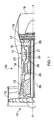
- FIG. 2 provides a schematic cross section of a rotor arrangement 30 in accordance with the present invention.
- the arrangement 30 comprises a rotor 31 secured upon a rotor hub 32.
- the rotor hub 32 and associated blades or rotors 31 rotate about an axis X-X past a stator 33 in a set of stators associated with a stator shroud 34.
- the primary function of the rotors 31 is to provide a powerful fluid flow in the direction of arrowheads A.
- a particular problem is with respect to secondary flows about the hub 32 and shroud 34 sweeping low momentum fluid upwards in the direction of arrowheads E causing problems at the peak suction point on the suction surface of the rotors 31.
- figure 2 only illustrates one rotor 31 and one stator 33 but in a practical engine there will be a plurality of such rotors 31 and stators 33.
- the rotors 31 on the hub 32 will sweep past the stators 33 for fluid flow control.
- the stator shroud 34 includes a collector slot 35 and an outlet slot 36 angled relative to each other for flow coupling with a return slot 37 in the rotor hub 32.
- secondary flow is collected at an inlet 38 of the collector slot 35 and passes along a collector passage towards the return slot 37.
- the collected flow is projected and given impulse by rotation of the rotor hub 32 as it sweeps past the shroud 34.
- the return slot 37 pumps the collected secondary flow towards the outlet passage 36 where it is taken sufficiently downstream and angled sufficiently such that there are no, or at least fewer, problems with regard to sweeping low momentum fluid upwards into the main fluid flow A.
- Arrowheads C illustrate a notional secondary flow path through the slots 35, 36, 37 in accordance with the present invention.
- secondary flow C is initially collected and drawn into the collector slot 35 in the direction of arrowhead Ca then expelled across a gap 39 between the collector slot 35 and the return slot 37 in the direction of arrowhead Cb where that collected secondary flow is "pumped" and given impetus for return in the direction of arrowhead Cc, again across the gap 39 and into the outlet slot 36 where it is propelled along as flow Cd for release through the outlet 40.
- impetus to the collected flow is provided by rotation of the rotating hub 32. This impetus is to stimulate appropriate displacement of the secondary flow along the slots 35, 36, 37. However, it is also important that the relative sizes, angles and positioning of the slots 35, 36, 37 as well as the gap 39 are considered.
- the slot 35 through the inlet 38, collects annulus fluid (secondary fluid) about an upper surface 41 of the hub 34.
- This collected secondary fluid Ca is drawn, possibly by a displacement effect, and moved towards the return slot 37.
- the inlet 38 would be arranged to have a sharp turn into a collector passage forming the collector slot 35. It will be appreciated that by appropriate angling such drawing and collecting of the annulus secondary flows into the collector slot 35 is achieved and facilitated.
- the collector slot 35 is arranged to be in the direction of sweep or travel for the hub 32 as it rotates.
- Figure 3 illustrates the collector slot 35 angled towards the direction of rotation illustrated by arrowhead D. In such circumstances the windage and other effects caused by rotation of the rotor hub 32 will facilitate drawing of fluid through the inlet 38 and along the slot 35.
- the return slots 37 are generally rounded to turn and provide impetus to the collected secondary flows.
- the return slots 37 are generally half moon shaped and utilised as indicated to provide impetus to the secondary flow Cb taken from the collector slot 35.
- a secondary flow Cb is turned and given impetus projection in the direction of arrowheads Cc. It will be understood that the output from the collector passage 35 is projected across the gap 39 and is then incident upon a hub surface 32 where it will be collected and as indicated provided with impetus by the rounded shaping of the return slots 37.
- the return slots 37 are generally half moon shaped in order to draw and project the collected secondary flow Cc towards the outlet passage 36.
- the outlet passage 36 is generally angled away from the direction of sweep rotation shown by arrowhead D. It will be noted that the respective levels of the outlet from the collector passage 35 and the inlet for the outlet passage 36 are generally presented at different heights such that the respective cross flows Cb, Cc do not directly impinge with each other. It will be understood that the impetus provided by the return slot 37 will at least partially collimate the returned collected secondary flow Cc such that it becomes incident upon the inlet for the outlet passage of the outlet slot 36, if the arrangement is properly or desirably configured.
- the collector passage of the collector slot 35 will be narrower than the width of the outlet passage of the outlet slot 36 again to provide a "bias" or easier direction of flow towards the outlet slot 36 compared to back along the collector slot 35.
- the slots 35, 36, 37 in accordance with the invention will typically be round it will be appreciated that the outlet slot 36 will have a greater diameter than the collector slot 35.
- the size and dimensions as well as the angle of the return slots 37 will be such that they are arranged to receive the collected secondary flow Cb and provide impetus and projection for that collected secondary flow towards the outlet slot 36.
- the return slots 37 will have a half moon shape in order to utilise the rotation of the hub 32 to generate impetus in the flow Cc toward the outlet slot 36.
- the return slots 37 may include a wider dimension towards a bottom edge 43 compared to an upper edge 44 in order to provide greater "nip" impetus on a "sling shot” projection basis of the collected secondary flow Cc towards the outlet passage 36.
- the present invention may also be utilised with regard to windage from a stator and stator shroud 34.
- a stator upstream of a rotor may create secondary flows which could impinge upon the performance of that rotor downstream.
- Such windage would be in an area denoted 45 in figure 2 .
- this windage may be utilised with regard to providing slots extending in the opposite direction to those described in the shroud 34 as well as a return slot in the downstream rotor hub to facilitate and remove secondary air impinging upon the performance of the arrangement.
- the inlet 38 for the collector slots 35 as well as outlets 40 for the outlet slots 36 are generally in the upper surface 41 of the shroud 34.
- the outlet flow Cd as indicated has impetus and therefore is dispersed more readily to avoid forcing low momentum air to impinge upon the major flow A.
Landscapes
- Engineering & Computer Science (AREA)
- Physics & Mathematics (AREA)
- Fluid Mechanics (AREA)
- Mechanical Engineering (AREA)
- General Engineering & Computer Science (AREA)
- Structures Of Non-Positive Displacement Pumps (AREA)
- Exhaust Gas After Treatment (AREA)
Abstract
Description
- The present invention relates to rotor arrangements and more particularly rotor arrangements utilised in gas turbine engines in the region of rotor hubs and stator shrouds.
- Referring to
Fig. 1 , a gas turbine engine is generally indicated at 10 and comprises, in axial flow series, an air intake 11, apropulsive fan 12, an intermediate pressure compressor 13, ahigh pressure compressor 14, acombustor 15, a turbine arrangement comprising ahigh pressure turbine 16, an intermediate pressure turbine 17 and alow pressure turbine 18, and anexhaust nozzle 19. - The gas turbine engine 10 operates in a conventional manner so that air entering the intake 11 is accelerated by the
fan 12 which produce two air flows: a first air flow into the intermediate pressure compressor 13 and a second air flow which provides propulsive thrust. The intermediate pressure compressor compresses the air flow directed into it before delivering that air to thehigh pressure compressor 14 where further compression takes place. - The compressed air exhausted from the
high pressure compressor 14 is directed into thecombustor 15 where it is mixed with fuel and the mixture combusted. The resultant hot combustion products then expand through, and thereby drive, the high, intermediate andlow pressure turbines nozzle 19 to provide additional propulsive thrust. The high, intermediate andlow pressure turbines intermediate pressure compressors 14 and 13 and thefan 12 by suitable interconnecting shafts. - In view of the above it will be appreciated that control of flows through a gas turbine engine are important to achieve efficiency and operational performance. In such circumstances in order to extract propulsion and work blades secured upon rotor hubs are associated with stators to cause appropriate directionality with respect to flows through an engine. It will also be appreciated that the loads presented to the engine may vary over operational cycles such as takeoff, cruise, ascent, descent and landing if the engine is utilised for aircraft propulsion. It is found that highly loaded rotors and stators stall about the hub/shroud area due to secondary flows sweeping low momentum fluid from the annulus about the rotor hub and stator shroud onto the stator blades near to the peak suction point on the suction surface of the blades. In such circumstances subsequent operation is less efficient and effective over those blade suction surfaces. It would be advantageous to reduce or inhibit the effects of such secondary flows to improve engine efficiency and performance.
- It will be appreciated that secondary flows relate to fluid flows through the engine blades near to the hub or shroud surface which are not part of or of lower momentum than the primary propulsion flows.
- In accordance with the present invention there is provided a rotor arrangement for a gas turbine engine, and a gas turbine engine including such a rotor arrangement, as set out in the claims.
- Aspects of the invention will now be described, by way of example, with reference to the accompanying drawings in which:
-
Figure 2 is a schematic side illustration of a rotor and stator arrangement in accordance with the present invention; and, -
Figure 3 is a schematic part plan cross section of the rotor and stator arrangement as depicted infigure 2 . - As indicated above secondary fluid flows about a stator hub can diminish operational efficiency and performance within a gas turbine engine. It will be appreciated that a rotor or compressor blade assembly generates fluid flow as it is turned and therefore any slower momentum fluid swept onto the blades from the annulus, that is to say the rotor hub, will diminish performance.
-
- In accordance with the present invention an arrangement is provided to efficiently evacuate secondary flows when performance requires it. The driven sweeping action of the rotor hub is utilised in order to provide impulse to the secondary flow away from areas of too detrimental effect. It is this rotor movement that is used to pump this secondary flow.
-
Figure 2 provides a schematic cross section of arotor arrangement 30 in accordance with the present invention. Thearrangement 30 comprises arotor 31 secured upon arotor hub 32. Therotor hub 32 and associated blades orrotors 31 rotate about an axis X-X past astator 33 in a set of stators associated with astator shroud 34. The primary function of therotors 31 is to provide a powerful fluid flow in the direction of arrowheads A. As indicated above a particular problem is with respect to secondary flows about thehub 32 andshroud 34 sweeping low momentum fluid upwards in the direction of arrowheads E causing problems at the peak suction point on the suction surface of therotors 31. It will be appreciated thatfigure 2 only illustrates onerotor 31 and onestator 33 but in a practical engine there will be a plurality ofsuch rotors 31 andstators 33. Therotors 31 on thehub 32 will sweep past thestators 33 for fluid flow control. - In accordance with the present invention, the
stator shroud 34 includes acollector slot 35 and anoutlet slot 36 angled relative to each other for flow coupling with areturn slot 37 in therotor hub 32. In operation, secondary flow is collected at aninlet 38 of thecollector slot 35 and passes along a collector passage towards thereturn slot 37. The collected flow is projected and given impulse by rotation of therotor hub 32 as it sweeps past theshroud 34. Thus, thereturn slot 37 pumps the collected secondary flow towards theoutlet passage 36 where it is taken sufficiently downstream and angled sufficiently such that there are no, or at least fewer, problems with regard to sweeping low momentum fluid upwards into the main fluid flow A. - Arrowheads C illustrate a notional secondary flow path through the
slots collector slot 35 in the direction of arrowhead Ca then expelled across agap 39 between thecollector slot 35 and thereturn slot 37 in the direction of arrowhead Cb where that collected secondary flow is "pumped" and given impetus for return in the direction of arrowhead Cc, again across thegap 39 and into theoutlet slot 36 where it is propelled along as flow Cd for release through theoutlet 40. - As will be appreciated, impetus to the collected flow is provided by rotation of the rotating
hub 32. This impetus is to stimulate appropriate displacement of the secondary flow along theslots slots gap 39 are considered. - The
slot 35, through theinlet 38, collects annulus fluid (secondary fluid) about anupper surface 41 of thehub 34. This collected secondary fluid Ca is drawn, possibly by a displacement effect, and moved towards thereturn slot 37. In order to facilitate collection, generally theinlet 38 would be arranged to have a sharp turn into a collector passage forming thecollector slot 35. It will be appreciated that by appropriate angling such drawing and collecting of the annulus secondary flows into thecollector slot 35 is achieved and facilitated. Generally thecollector slot 35 is arranged to be in the direction of sweep or travel for thehub 32 as it rotates.Figure 3 illustrates thecollector slot 35 angled towards the direction of rotation illustrated by arrowhead D. In such circumstances the windage and other effects caused by rotation of therotor hub 32 will facilitate drawing of fluid through theinlet 38 and along theslot 35. - The
return slots 37 are generally rounded to turn and provide impetus to the collected secondary flows. Thereturn slots 37 are generally half moon shaped and utilised as indicated to provide impetus to the secondary flow Cb taken from thecollector slot 35. As can be seen in thegap 39, a secondary flow Cb is turned and given impetus projection in the direction of arrowheads Cc. It will be understood that the output from thecollector passage 35 is projected across thegap 39 and is then incident upon ahub surface 32 where it will be collected and as indicated provided with impetus by the rounded shaping of thereturn slots 37. Thereturn slots 37 are generally half moon shaped in order to draw and project the collected secondary flow Cc towards theoutlet passage 36. - The
outlet passage 36 is generally angled away from the direction of sweep rotation shown by arrowhead D. It will be noted that the respective levels of the outlet from thecollector passage 35 and the inlet for theoutlet passage 36 are generally presented at different heights such that the respective cross flows Cb, Cc do not directly impinge with each other. It will be understood that the impetus provided by thereturn slot 37 will at least partially collimate the returned collected secondary flow Cc such that it becomes incident upon the inlet for the outlet passage of theoutlet slot 36, if the arrangement is properly or desirably configured. - As indicated above, coupling of the flow C across the
slots gap 39 is achieved. It will be understood that the relative sizing of the slots as indicated will depend upon operational conditions and speed of rotation in the direction of arrowhead D andgap width 39. Typically, a consideration will be made of operational conditions andslot slots inlet 38 and a smoothcurved exit 40. Thus, once secondary flow is within the thrall of the arrangement in accordance with the invention there is a resistance to back flow caused by the sharp turn at theinlet 38 relative to theoutlet 40. Typically, the collector passage of thecollector slot 35 will be narrower than the width of the outlet passage of theoutlet slot 36 again to provide a "bias" or easier direction of flow towards theoutlet slot 36 compared to back along thecollector slot 35. As theslots outlet slot 36 will have a greater diameter than thecollector slot 35. - The size and dimensions as well as the angle of the
return slots 37 will be such that they are arranged to receive the collected secondary flow Cb and provide impetus and projection for that collected secondary flow towards theoutlet slot 36. In such circumstance as indicated above generally, thereturn slots 37 will have a half moon shape in order to utilise the rotation of thehub 32 to generate impetus in the flow Cc toward theoutlet slot 36. It is possible that thereturn slots 37 may include a wider dimension towards abottom edge 43 compared to anupper edge 44 in order to provide greater "nip" impetus on a "sling shot" projection basis of the collected secondary flow Cc towards theoutlet passage 36. - It will be understood that with the collected secondary flow Cd presented with impetus further downstream of the
stator 33 as indicated above will mean there is less likelihood of causing displacement of low momentum fluid upwards into the main flow A and therefore diminishing performance. The number ofslots respective shroud 34 and thehub 32 will depend upon operational requirements and performance. - It will be understood that the present invention may also be utilised with regard to windage from a stator and
stator shroud 34. In such circumstance it will be appreciated that a stator upstream of a rotor may create secondary flows which could impinge upon the performance of that rotor downstream. Such windage would be in an area denoted 45 infigure 2 . In such circumstances, this windage may be utilised with regard to providing slots extending in the opposite direction to those described in theshroud 34 as well as a return slot in the downstream rotor hub to facilitate and remove secondary air impinging upon the performance of the arrangement. - As can be seen the
inlet 38 for thecollector slots 35 as well asoutlets 40 for theoutlet slots 36 are generally in theupper surface 41 of theshroud 34. By the present invention the outlet flow Cd as indicated has impetus and therefore is dispersed more readily to avoid forcing low momentum air to impinge upon the major flow A. - Modifications and alterations to the present invention will be appreciated by those skilled in the art. Thus, as indicated above the angles and dimensions of the
slots gap 39 is important with respect to the efficiency of coupling of the flows Cb and Cc. Thisgap 39 may vary in width dependant upon operational temperature and therefore the configuration, size and distribution of the slots arranged to reciprocate such variations in use. The configuration, size and distribution will be set for the gap at the normal operational temperature of the arrangement.
Claims (14)
- A rotor arrangement for a gas turbine engine, the arrangement comprising a rotor hub (32) and a stator shroud (34) arranged to sweep past each other in use, the stator shroud including a collector slot (35) to collect secondary flow, characterised by the collector slot arranged to direct the collected secondary flow to a return slot (37) in the rotor hub, the return slot shaped to provide in use impulse to the collected secondary flow to project the collected secondary flow to an outlet slot (36) in the stator shroud, the collector slot and the outlet slot respectively angled relative to the return slot to facilitate coupling as the rotor hub sweeps past the stator shroud in use.
- An arrangement as claimed in claim 1 wherein the collector slot has an inlet in an upper surface (41) of the stator shroud.
- An arrangement as claimed in claim 1 or claim 2 wherein the collector slot has a collector passage at an angle towards the direction of rotation of the rotor hub in use.
- An arrangement as claimed in claim 3 when dependent upon claim 2 wherein the inlet (38) has a sharp bend into the collector passage.
- An arrangement as claimed in any preceding claim wherein the outlet slot has an outlet in the upper surface of the stator shroud.
- An arrangement as claimed in any preceding claim wherein the outlet slot has an outlet passage at an angle away from the direction of rotation of the rotor hub in use.
- An arrangement as claimed in claim 6 when dependant upon claim 5 wherein the outlet (40) extends with a rounded bend from the outlet passage.
- An arrangement as claimed in claim 3 and claim 6, or any claim dependant thereon, wherein the outlet passage has a greater width than the collector passage.
- An arrangement as claimed in claim 2 and claim 5, or any claim dependant thereon, wherein the outlet has a greater width than the inlet.
- An arrangement as claimed in any preceding claim wherein the return slot is rounded.
- An arrangement as claimed in any preceding claim wherein the return slot is half moon shaped.
- An arrangement as claimed in any preceding claim wherein the return slot is angled away from the direction of rotation of the rotor hub in use.
- An arrangement as claimed in any preceding claim wherein there is a plurality of collector slots and/or return slots and/or outlet slots.
- A gas turbine engine including a rotor arrangement as claimed in any preceding claim.
Applications Claiming Priority (1)
| Application Number | Priority Date | Filing Date | Title |
|---|---|---|---|
| GBGB0905548.4A GB0905548D0 (en) | 2009-04-01 | 2009-04-01 | A rotor arrangement |
Publications (3)
| Publication Number | Publication Date |
|---|---|
| EP2236748A2 EP2236748A2 (en) | 2010-10-06 |
| EP2236748A3 EP2236748A3 (en) | 2013-02-20 |
| EP2236748B1 true EP2236748B1 (en) | 2014-01-29 |
Family
ID=40672038
Family Applications (1)
| Application Number | Title | Priority Date | Filing Date |
|---|---|---|---|
| EP10250348.9A Not-in-force EP2236748B1 (en) | 2009-04-01 | 2010-02-26 | A rotor arrangement for a gas turbine |
Country Status (3)
| Country | Link |
|---|---|
| US (1) | US8282341B2 (en) |
| EP (1) | EP2236748B1 (en) |
| GB (1) | GB0905548D0 (en) |
Families Citing this family (9)
| Publication number | Priority date | Publication date | Assignee | Title |
|---|---|---|---|---|
| DE102008011746A1 (en) * | 2008-02-28 | 2009-09-03 | Mtu Aero Engines Gmbh | Device and method for diverting a leakage current |
| US8864452B2 (en) * | 2011-07-12 | 2014-10-21 | Siemens Energy, Inc. | Flow directing member for gas turbine engine |
| US9091180B2 (en) * | 2012-07-19 | 2015-07-28 | Siemens Energy, Inc. | Airfoil assembly including vortex reducing at an airfoil leading edge |
| US9845694B2 (en) | 2015-04-22 | 2017-12-19 | United Technologies Corporation | Flow directing cover for engine component |
| DE102015224259A1 (en) | 2015-12-04 | 2017-06-08 | MTU Aero Engines AG | Run-on surface for vane cover and blade base plate |
| CN111946666B (en) * | 2020-07-20 | 2022-04-19 | 中国科学院工程热物理研究所 | Axial compressor end wall boundary layer flow regulation and control structure |
| FR3117532B1 (en) * | 2020-12-10 | 2024-05-24 | Safran Aircraft Engines | Turbine blade for an aircraft turbomachine, provided with a primary flow ejection channel towards an inter-lip cavity |
| JP7603547B2 (en) * | 2021-07-26 | 2024-12-20 | 三菱重工業株式会社 | aircraft |
| FR3133063B1 (en) * | 2022-02-25 | 2024-08-02 | Safran Aircraft Engines | Turbomachine blading, comprising a blade and a platform which has an internal flow suction and ejection channel. |
Family Cites Families (10)
| Publication number | Priority date | Publication date | Assignee | Title |
|---|---|---|---|---|
| GB479427A (en) | 1935-05-31 | 1938-01-31 | Gyoergy Jendrassik | Improvements in rotary compressors |
| US2291828A (en) * | 1940-05-04 | 1942-08-04 | Westinghouse Electric & Mfg Co | Turbine blading |
| GB678085A (en) * | 1949-02-15 | 1952-08-27 | Rolls Royce | Improvements in or relating to compressors and turbines |
| US3291447A (en) * | 1965-02-15 | 1966-12-13 | Gen Electric | Steam turbine rotor cooling |
| JPS501646B1 (en) * | 1970-07-11 | 1975-01-20 | ||
| GB2165007B (en) * | 1980-11-11 | 1986-08-20 | Rolls Royce | Rotor and stator assembly for a gas turbine engine |
| US5562404A (en) * | 1994-12-23 | 1996-10-08 | United Technologies Corporation | Vaned passage hub treatment for cantilever stator vanes |
| DE59709701D1 (en) * | 1997-09-15 | 2003-05-08 | Alstom Switzerland Ltd | Platform cooling for gas turbines |
| US7722315B2 (en) * | 2006-11-30 | 2010-05-25 | General Electric Company | Method and system to facilitate preferentially distributed recuperated film cooling of turbine shroud assembly |
| GB2452297B (en) | 2007-08-30 | 2010-01-06 | Rolls Royce Plc | A compressor |
-
2009
- 2009-04-01 GB GBGB0905548.4A patent/GB0905548D0/en not_active Ceased
-
2010
- 2010-02-25 US US12/712,853 patent/US8282341B2/en not_active Expired - Fee Related
- 2010-02-26 EP EP10250348.9A patent/EP2236748B1/en not_active Not-in-force
Also Published As
| Publication number | Publication date |
|---|---|
| US8282341B2 (en) | 2012-10-09 |
| EP2236748A3 (en) | 2013-02-20 |
| US20100254802A1 (en) | 2010-10-07 |
| GB0905548D0 (en) | 2009-05-13 |
| EP2236748A2 (en) | 2010-10-06 |
Similar Documents
| Publication | Publication Date | Title |
|---|---|---|
| US8282341B2 (en) | Rotor arrangement | |
| US11300136B2 (en) | Aircraft fan with low part-span solidity | |
| US8231341B2 (en) | Hybrid compressor | |
| US8684698B2 (en) | Compressor airfoil with tip dihedral | |
| EP3026214B1 (en) | Airfoil with stepped spanwise thickness distribution | |
| CN108952823B (en) | Method and system for leading edge auxiliary blade | |
| EP2520763B1 (en) | Impeller | |
| KR101891853B1 (en) | Centrifugal Compressor Impeller | |
| CN103184897B (en) | There is the gas turbine nozzle of airflow fence | |
| EP2775119B1 (en) | Compressor shroud reverse bleed holes | |
| EP2778427A2 (en) | Compressor bleed self-recirculating system | |
| JP2001271792A (en) | Fluted compressor channel | |
| US10385871B2 (en) | Method and system for compressor vane leading edge auxiliary vanes | |
| US8152456B2 (en) | Turbojet compressor | |
| CN115807710A (en) | Inlet for ductless propulsion systems | |
| EP3225852A1 (en) | Gas turbine engine fan assembly | |
| RU2727823C2 (en) | Turbomachine rotor blade, disc with blades, rotor and turbomachine | |
| CA2877222C (en) | Multistage axial flow compressor | |
| US7789631B2 (en) | Compressor of a gas turbine and gas turbine | |
| US10519976B2 (en) | Fluid diodes with ridges to control boundary layer in axial compressor stator vane | |
| CA3081253A1 (en) | Gas turbine impeller nose cone | |
| EP3770379A1 (en) | Compressor stator | |
| US12071959B1 (en) | Compressor casing with slots and grooves | |
| CA2658412C (en) | Hybrid compressor | |
| KR20110083363A (en) | Impeller and compressor |
Legal Events
| Date | Code | Title | Description |
|---|---|---|---|
| PUAI | Public reference made under article 153(3) epc to a published international application that has entered the european phase |
Free format text: ORIGINAL CODE: 0009012 |
|
| AK | Designated contracting states |
Kind code of ref document: A2 Designated state(s): AT BE BG CH CY CZ DE DK EE ES FI FR GB GR HR HU IE IS IT LI LT LU LV MC MK MT NL NO PL PT RO SE SI SK SM TR |
|
| AX | Request for extension of the european patent |
Extension state: AL BA RS |
|
| PUAL | Search report despatched |
Free format text: ORIGINAL CODE: 0009013 |
|
| AK | Designated contracting states |
Kind code of ref document: A3 Designated state(s): AT BE BG CH CY CZ DE DK EE ES FI FR GB GR HR HU IE IS IT LI LT LU LV MC MK MT NL NO PL PT RO SE SI SK SM TR |
|
| AX | Request for extension of the european patent |
Extension state: AL BA RS |
|
| RIC1 | Information provided on ipc code assigned before grant |
Ipc: F01D 5/14 20060101AFI20130111BHEP |
|
| 17P | Request for examination filed |
Effective date: 20130820 |
|
| GRAP | Despatch of communication of intention to grant a patent |
Free format text: ORIGINAL CODE: EPIDOSNIGR1 |
|
| INTG | Intention to grant announced |
Effective date: 20131004 |
|
| GRAS | Grant fee paid |
Free format text: ORIGINAL CODE: EPIDOSNIGR3 |
|
| GRAA | (expected) grant |
Free format text: ORIGINAL CODE: 0009210 |
|
| AK | Designated contracting states |
Kind code of ref document: B1 Designated state(s): AT BE BG CH CY CZ DE DK EE ES FI FR GB GR HR HU IE IS IT LI LT LU LV MC MK MT NL NO PL PT RO SE SI SK SM TR |
|
| REG | Reference to a national code |
Ref country code: GB Ref legal event code: FG4D |
|
| REG | Reference to a national code |
Ref country code: CH Ref legal event code: EP |
|
| REG | Reference to a national code |
Ref country code: AT Ref legal event code: REF Ref document number: 651582 Country of ref document: AT Kind code of ref document: T Effective date: 20140215 |
|
| REG | Reference to a national code |
Ref country code: IE Ref legal event code: FG4D |
|
| REG | Reference to a national code |
Ref country code: DE Ref legal event code: R096 Ref document number: 602010013398 Country of ref document: DE Effective date: 20140313 |
|
| REG | Reference to a national code |
Ref country code: AT Ref legal event code: MK05 Ref document number: 651582 Country of ref document: AT Kind code of ref document: T Effective date: 20140129 |
|
| REG | Reference to a national code |
Ref country code: NL Ref legal event code: VDEP Effective date: 20140129 |
|
| REG | Reference to a national code |
Ref country code: LT Ref legal event code: MG4D |
|
| PG25 | Lapsed in a contracting state [announced via postgrant information from national office to epo] |
Ref country code: LT Free format text: LAPSE BECAUSE OF FAILURE TO SUBMIT A TRANSLATION OF THE DESCRIPTION OR TO PAY THE FEE WITHIN THE PRESCRIBED TIME-LIMIT Effective date: 20140129 Ref country code: NO Free format text: LAPSE BECAUSE OF FAILURE TO SUBMIT A TRANSLATION OF THE DESCRIPTION OR TO PAY THE FEE WITHIN THE PRESCRIBED TIME-LIMIT Effective date: 20140429 Ref country code: IS Free format text: LAPSE BECAUSE OF FAILURE TO SUBMIT A TRANSLATION OF THE DESCRIPTION OR TO PAY THE FEE WITHIN THE PRESCRIBED TIME-LIMIT Effective date: 20140529 |
|
| PG25 | Lapsed in a contracting state [announced via postgrant information from national office to epo] |
Ref country code: NL Free format text: LAPSE BECAUSE OF FAILURE TO SUBMIT A TRANSLATION OF THE DESCRIPTION OR TO PAY THE FEE WITHIN THE PRESCRIBED TIME-LIMIT Effective date: 20140129 Ref country code: ES Free format text: LAPSE BECAUSE OF FAILURE TO SUBMIT A TRANSLATION OF THE DESCRIPTION OR TO PAY THE FEE WITHIN THE PRESCRIBED TIME-LIMIT Effective date: 20140129 Ref country code: CY Free format text: LAPSE BECAUSE OF FAILURE TO SUBMIT A TRANSLATION OF THE DESCRIPTION OR TO PAY THE FEE WITHIN THE PRESCRIBED TIME-LIMIT Effective date: 20140129 Ref country code: FI Free format text: LAPSE BECAUSE OF FAILURE TO SUBMIT A TRANSLATION OF THE DESCRIPTION OR TO PAY THE FEE WITHIN THE PRESCRIBED TIME-LIMIT Effective date: 20140129 Ref country code: AT Free format text: LAPSE BECAUSE OF FAILURE TO SUBMIT A TRANSLATION OF THE DESCRIPTION OR TO PAY THE FEE WITHIN THE PRESCRIBED TIME-LIMIT Effective date: 20140129 Ref country code: PT Free format text: LAPSE BECAUSE OF FAILURE TO SUBMIT A TRANSLATION OF THE DESCRIPTION OR TO PAY THE FEE WITHIN THE PRESCRIBED TIME-LIMIT Effective date: 20140529 Ref country code: SE Free format text: LAPSE BECAUSE OF FAILURE TO SUBMIT A TRANSLATION OF THE DESCRIPTION OR TO PAY THE FEE WITHIN THE PRESCRIBED TIME-LIMIT Effective date: 20140129 |
|
| PG25 | Lapsed in a contracting state [announced via postgrant information from national office to epo] |
Ref country code: BE Free format text: LAPSE BECAUSE OF FAILURE TO SUBMIT A TRANSLATION OF THE DESCRIPTION OR TO PAY THE FEE WITHIN THE PRESCRIBED TIME-LIMIT Effective date: 20140129 Ref country code: HR Free format text: LAPSE BECAUSE OF FAILURE TO SUBMIT A TRANSLATION OF THE DESCRIPTION OR TO PAY THE FEE WITHIN THE PRESCRIBED TIME-LIMIT Effective date: 20140129 Ref country code: LV Free format text: LAPSE BECAUSE OF FAILURE TO SUBMIT A TRANSLATION OF THE DESCRIPTION OR TO PAY THE FEE WITHIN THE PRESCRIBED TIME-LIMIT Effective date: 20140129 |
|
| REG | Reference to a national code |
Ref country code: CH Ref legal event code: PL |
|
| REG | Reference to a national code |
Ref country code: DE Ref legal event code: R097 Ref document number: 602010013398 Country of ref document: DE |
|
| PG25 | Lapsed in a contracting state [announced via postgrant information from national office to epo] |
Ref country code: DK Free format text: LAPSE BECAUSE OF FAILURE TO SUBMIT A TRANSLATION OF THE DESCRIPTION OR TO PAY THE FEE WITHIN THE PRESCRIBED TIME-LIMIT Effective date: 20140129 Ref country code: RO Free format text: LAPSE BECAUSE OF FAILURE TO SUBMIT A TRANSLATION OF THE DESCRIPTION OR TO PAY THE FEE WITHIN THE PRESCRIBED TIME-LIMIT Effective date: 20140129 Ref country code: CZ Free format text: LAPSE BECAUSE OF FAILURE TO SUBMIT A TRANSLATION OF THE DESCRIPTION OR TO PAY THE FEE WITHIN THE PRESCRIBED TIME-LIMIT Effective date: 20140129 Ref country code: LI Free format text: LAPSE BECAUSE OF NON-PAYMENT OF DUE FEES Effective date: 20140228 Ref country code: CH Free format text: LAPSE BECAUSE OF NON-PAYMENT OF DUE FEES Effective date: 20140228 Ref country code: EE Free format text: LAPSE BECAUSE OF FAILURE TO SUBMIT A TRANSLATION OF THE DESCRIPTION OR TO PAY THE FEE WITHIN THE PRESCRIBED TIME-LIMIT Effective date: 20140129 |
|
| PG25 | Lapsed in a contracting state [announced via postgrant information from national office to epo] |
Ref country code: PL Free format text: LAPSE BECAUSE OF FAILURE TO SUBMIT A TRANSLATION OF THE DESCRIPTION OR TO PAY THE FEE WITHIN THE PRESCRIBED TIME-LIMIT Effective date: 20140129 Ref country code: SK Free format text: LAPSE BECAUSE OF FAILURE TO SUBMIT A TRANSLATION OF THE DESCRIPTION OR TO PAY THE FEE WITHIN THE PRESCRIBED TIME-LIMIT Effective date: 20140129 |
|
| REG | Reference to a national code |
Ref country code: IE Ref legal event code: MM4A |
|
| PLBE | No opposition filed within time limit |
Free format text: ORIGINAL CODE: 0009261 |
|
| STAA | Information on the status of an ep patent application or granted ep patent |
Free format text: STATUS: NO OPPOSITION FILED WITHIN TIME LIMIT |
|
| 26N | No opposition filed |
Effective date: 20141030 |
|
| PG25 | Lapsed in a contracting state [announced via postgrant information from national office to epo] |
Ref country code: IE Free format text: LAPSE BECAUSE OF NON-PAYMENT OF DUE FEES Effective date: 20140226 |
|
| REG | Reference to a national code |
Ref country code: DE Ref legal event code: R097 Ref document number: 602010013398 Country of ref document: DE Effective date: 20141030 |
|
| REG | Reference to a national code |
Ref country code: FR Ref legal event code: PLFP Year of fee payment: 6 |
|
| PGFP | Annual fee paid to national office [announced via postgrant information from national office to epo] |
Ref country code: DE Payment date: 20150226 Year of fee payment: 6 |
|
| PG25 | Lapsed in a contracting state [announced via postgrant information from national office to epo] |
Ref country code: SI Free format text: LAPSE BECAUSE OF FAILURE TO SUBMIT A TRANSLATION OF THE DESCRIPTION OR TO PAY THE FEE WITHIN THE PRESCRIBED TIME-LIMIT Effective date: 20140129 |
|
| REG | Reference to a national code |
Ref country code: FR Ref legal event code: PLFP Year of fee payment: 7 |
|
| PG25 | Lapsed in a contracting state [announced via postgrant information from national office to epo] |
Ref country code: MT Free format text: LAPSE BECAUSE OF FAILURE TO SUBMIT A TRANSLATION OF THE DESCRIPTION OR TO PAY THE FEE WITHIN THE PRESCRIBED TIME-LIMIT Effective date: 20140129 |
|
| PG25 | Lapsed in a contracting state [announced via postgrant information from national office to epo] |
Ref country code: SM Free format text: LAPSE BECAUSE OF FAILURE TO SUBMIT A TRANSLATION OF THE DESCRIPTION OR TO PAY THE FEE WITHIN THE PRESCRIBED TIME-LIMIT Effective date: 20140129 |
|
| PG25 | Lapsed in a contracting state [announced via postgrant information from national office to epo] |
Ref country code: MC Free format text: LAPSE BECAUSE OF FAILURE TO SUBMIT A TRANSLATION OF THE DESCRIPTION OR TO PAY THE FEE WITHIN THE PRESCRIBED TIME-LIMIT Effective date: 20140129 |
|
| PGFP | Annual fee paid to national office [announced via postgrant information from national office to epo] |
Ref country code: FR Payment date: 20160217 Year of fee payment: 7 |
|
| PG25 | Lapsed in a contracting state [announced via postgrant information from national office to epo] |
Ref country code: IT Free format text: LAPSE BECAUSE OF FAILURE TO SUBMIT A TRANSLATION OF THE DESCRIPTION OR TO PAY THE FEE WITHIN THE PRESCRIBED TIME-LIMIT Effective date: 20140129 Ref country code: BG Free format text: LAPSE BECAUSE OF FAILURE TO SUBMIT A TRANSLATION OF THE DESCRIPTION OR TO PAY THE FEE WITHIN THE PRESCRIBED TIME-LIMIT Effective date: 20140129 Ref country code: GR Free format text: LAPSE BECAUSE OF FAILURE TO SUBMIT A TRANSLATION OF THE DESCRIPTION OR TO PAY THE FEE WITHIN THE PRESCRIBED TIME-LIMIT Effective date: 20140430 |
|
| PG25 | Lapsed in a contracting state [announced via postgrant information from national office to epo] |
Ref country code: TR Free format text: LAPSE BECAUSE OF FAILURE TO SUBMIT A TRANSLATION OF THE DESCRIPTION OR TO PAY THE FEE WITHIN THE PRESCRIBED TIME-LIMIT Effective date: 20140129 Ref country code: LU Free format text: LAPSE BECAUSE OF NON-PAYMENT OF DUE FEES Effective date: 20140226 Ref country code: HU Free format text: LAPSE BECAUSE OF FAILURE TO SUBMIT A TRANSLATION OF THE DESCRIPTION OR TO PAY THE FEE WITHIN THE PRESCRIBED TIME-LIMIT; INVALID AB INITIO Effective date: 20100226 |
|
| REG | Reference to a national code |
Ref country code: DE Ref legal event code: R119 Ref document number: 602010013398 Country of ref document: DE |
|
| PG25 | Lapsed in a contracting state [announced via postgrant information from national office to epo] |
Ref country code: DE Free format text: LAPSE BECAUSE OF NON-PAYMENT OF DUE FEES Effective date: 20160901 |
|
| REG | Reference to a national code |
Ref country code: FR Ref legal event code: ST Effective date: 20171031 |
|
| PG25 | Lapsed in a contracting state [announced via postgrant information from national office to epo] |
Ref country code: FR Free format text: LAPSE BECAUSE OF NON-PAYMENT OF DUE FEES Effective date: 20170228 |
|
| PG25 | Lapsed in a contracting state [announced via postgrant information from national office to epo] |
Ref country code: MK Free format text: LAPSE BECAUSE OF FAILURE TO SUBMIT A TRANSLATION OF THE DESCRIPTION OR TO PAY THE FEE WITHIN THE PRESCRIBED TIME-LIMIT Effective date: 20140129 |
|
| PGFP | Annual fee paid to national office [announced via postgrant information from national office to epo] |
Ref country code: GB Payment date: 20200227 Year of fee payment: 11 |
|
| GBPC | Gb: european patent ceased through non-payment of renewal fee |
Effective date: 20210226 |
|
| PG25 | Lapsed in a contracting state [announced via postgrant information from national office to epo] |
Ref country code: GB Free format text: LAPSE BECAUSE OF NON-PAYMENT OF DUE FEES Effective date: 20210226 |