EP2236364A1 - Windscreen wiper device - Google Patents
Windscreen wiper device Download PDFInfo
- Publication number
- EP2236364A1 EP2236364A1 EP09156718A EP09156718A EP2236364A1 EP 2236364 A1 EP2236364 A1 EP 2236364A1 EP 09156718 A EP09156718 A EP 09156718A EP 09156718 A EP09156718 A EP 09156718A EP 2236364 A1 EP2236364 A1 EP 2236364A1
- Authority
- EP
- European Patent Office
- Prior art keywords
- windscreen
- longitudinal strip
- wiper blade
- groove
- wiping element
- Prior art date
- Legal status (The legal status is an assumption and is not a legal conclusion. Google has not performed a legal analysis and makes no representation as to the accuracy of the status listed.)
- Granted
Links
Images

Classifications
-
- B—PERFORMING OPERATIONS; TRANSPORTING
- B60—VEHICLES IN GENERAL
- B60S—SERVICING, CLEANING, REPAIRING, SUPPORTING, LIFTING, OR MANOEUVRING OF VEHICLES, NOT OTHERWISE PROVIDED FOR
- B60S1/00—Cleaning of vehicles
- B60S1/02—Cleaning windscreens, windows or optical devices
- B60S1/04—Wipers or the like, e.g. scrapers
- B60S1/32—Wipers or the like, e.g. scrapers characterised by constructional features of wiper blade arms or blades
- B60S1/38—Wiper blades
- B60S1/3848—Flat-type wiper blade, i.e. without harness
- B60S1/3874—Flat-type wiper blade, i.e. without harness with a reinforcing vertebra
- B60S1/3875—Flat-type wiper blade, i.e. without harness with a reinforcing vertebra rectangular section
- B60S1/3877—Flat-type wiper blade, i.e. without harness with a reinforcing vertebra rectangular section embedded in the squeegee
-
- B—PERFORMING OPERATIONS; TRANSPORTING
- B60—VEHICLES IN GENERAL
- B60S—SERVICING, CLEANING, REPAIRING, SUPPORTING, LIFTING, OR MANOEUVRING OF VEHICLES, NOT OTHERWISE PROVIDED FOR
- B60S1/00—Cleaning of vehicles
- B60S1/02—Cleaning windscreens, windows or optical devices
- B60S1/04—Wipers or the like, e.g. scrapers
- B60S1/32—Wipers or the like, e.g. scrapers characterised by constructional features of wiper blade arms or blades
- B60S1/38—Wiper blades
- B60S1/3806—Means, or measures taken, for influencing the aerodynamic quality of the wiper blades
- B60S1/3808—Spoiler integral with the squeegee
-
- B—PERFORMING OPERATIONS; TRANSPORTING
- B60—VEHICLES IN GENERAL
- B60S—SERVICING, CLEANING, REPAIRING, SUPPORTING, LIFTING, OR MANOEUVRING OF VEHICLES, NOT OTHERWISE PROVIDED FOR
- B60S1/00—Cleaning of vehicles
- B60S1/02—Cleaning windscreens, windows or optical devices
- B60S1/04—Wipers or the like, e.g. scrapers
- B60S1/32—Wipers or the like, e.g. scrapers characterised by constructional features of wiper blade arms or blades
- B60S1/38—Wiper blades
- B60S2001/3812—Means of supporting or holding the squeegee or blade rubber
- B60S2001/3817—Means of supporting or holding the squeegee or blade rubber chacterised by a backing strip to aid mounting of squeegee in support
- B60S2001/382—Means of supporting or holding the squeegee or blade rubber chacterised by a backing strip to aid mounting of squeegee in support the backing strip being an essentially planar reinforcing strip, e.g. vertebra
-
- B—PERFORMING OPERATIONS; TRANSPORTING
- B60—VEHICLES IN GENERAL
- B60S—SERVICING, CLEANING, REPAIRING, SUPPORTING, LIFTING, OR MANOEUVRING OF VEHICLES, NOT OTHERWISE PROVIDED FOR
- B60S1/00—Cleaning of vehicles
- B60S1/02—Cleaning windscreens, windows or optical devices
- B60S1/04—Wipers or the like, e.g. scrapers
- B60S1/32—Wipers or the like, e.g. scrapers characterised by constructional features of wiper blade arms or blades
- B60S1/38—Wiper blades
- B60S2001/3827—Wiper blades characterised by the squeegee or blade rubber or wiping element
- B60S2001/3836—Wiper blades characterised by the squeegee or blade rubber or wiping element characterised by cross-sectional shape
Definitions
- the present invention relates to a windscreen wiper device comprising an elastic, elongated carrier element, as well as an elongated wiper blade of a flexible material, said wiper blade comprising a wiping element which can be placed in abutment with a windscreen to be wiped, which wiper blade includes a central longitudinal groove, in which groove a longitudinal strip of the carrier element is disposed, which windscreen wiper device comprises a connecting device for an oscillating arm, wherein said oscillating arm is pivotally connected to said connecting device about a pivot axis near one end thereof.
- Such a windscreen wiper device is generally known.
- This prior art windscreen wiper device is designed as a so-called “flat blade” or “yokeless blade”, wherein no use is made of several yokes pivotally connected to each other, but wherein the wiper blade is biassed by the carrier element, as a result of which it exhibits a specific curvature.
- the object of the invention is to provide an improved windscreen wiper device.
- a windscreen wiper device of the type referred to in the introduction is characterized according to the invention in that said wiping element is movable in a direction at least substantially perpendicular to a windscreen to be wiped, dependent on the pressure exerted by the oscillating arm on the wiper blade.
- the present windscreen wiper device can be used for large varieties of windscreens to be wiped mutually differing in their curvatures, as variation of the position of the wiping element perpendicular to a windscreen to be wiped may compensate these differences in curvature.
- any tolerances in windscreen shapes may thus be compensated.
- said wiping element is resilient between a first position facing away from the longitudinal strip and a second position facing towards the longitudinal strip.
- said wiping element is in said first position at a pressure A exerted by the longitudinal strip on the wiper blade, wherein said wiping element is in said second position at a pressure B exerted by the longitudinal strip arm on the wiper blade, and wherein pressure A is smaller than pressure B
- said groove extends in downward direction beneath the longitudinal strip for forming a longitudinal hollow channel defined by said longitudinal strip and a bottom of said groove.
- said bottom is flexible.
- said bottom is provided with stop surfaces on opposite sides of said wiping element, wherein said stop surfaces limit an oscillatory movement of said wiping element in said second position.
- said groove extends in upward direction above the longitudinal strip for forming a longitudinal hollow channel defined by said longitudinal strip and an upper surface of said groove.
- said wiper blade is provided with a spoiler at a side thereof facing away from a windscreen to be wiped.
- FIG. 1 shows a preferred variant of a windscreen wiper device 1 according to the invention.
- Said windscreen wiper device is built up of an elastomeric wiper blade 2 comprising a central or middle longitudinal groove 3, wherein a central or middle longitudinal strip 4 made of spring band steel is fitted in said longitudinal groove 3 (see figures 2 through 5 ).
- Said strip 4 forms a flexible carrier element for the rubber wiper blade 2, as it were, which is thus biassed in a curved position (the curvature in operative position being that of a windscreen to be wiped).
- An end of said strip 4 and/or an end of said wiperblade 2 is connected on either side of the windscreen wiper device 1 to respective connecting pieces or "end caps" 5.
- the connecting pieces 5 are separate constructional elements, which may be form-locked, as well as force-locked to both ends of said strip/4 said wiper blade.
- said connecting pieces 5 are in one piece with the strip 4 made of spring band steel.
- the windscreen wiper device 1 is furthermore built up of a connecting device 6 for connecting an oscillating wiper arm 7 thereto.
- the oscillating wiper arm 7 is pivotally connected to the connecting device 6 about a pivot axis near one end.
- the preferred embodiment of figure 1 according to the invention comprises a spoiler or "air deflector" 8 which is made in one piece with the rubber wiper blade 2 and which extends along the entire length thereof.
- the connecting device 6 with the wiper blade 2 is mounted onto the oscillating arm 7 as follows.
- a joint part 9 being already clipped onto the connecting device 6 is pivoted relative to the connecting device 6, so that said joint part 9 can be easily slided on a free end of the oscillating arm 7.
- a resilient tongue 10 of said joint part 9 is initially pushed in against a spring force and then allowed to spring back into said hole 11 of said oscillating arm 7, thus snapping, that is clipping the resilient tongue 10 into the hole 11.
- This is a so-called bayonet-connection.
- the oscillating arm 7 together with the joint part 9 may then be pivoted back in a position parallel to the wiper blade 2 in order to be ready for use.
- the connecting device 6 comprises two cylindrical protrusions 12 extending outwards on either side of said connecting device 6. These protrusions 12 pivotally engage in identically shaped cylindrical recesses 13 of the plastic joint part 9. Said protrusions 12 act as bearing surfaces at the location of the pivot axis in order to pivot the joint part 9 (and the oscillating arm 7 attached thereto) about the pivot axis near one end of the oscillating arm 7.
- said oscillating arm 7 is connected to a mounting head fixed for rotation to a shaft driven by a small motor.
- the shaft rotates alternately in a clockwise and in a counter-clockwise sense carrying the mounting head into rotation also, which in turn draws said oscillating arm 7 into rotation and by means of said connecting device 6 moves said wiper blade 2.
- the wiper blade 2 comprises a wiping element 14.
- Said wiping element 14 consists of two tilting web grooves 15 defining a strip-like tilting web 16 between them, as well as a downwardly extending wiping lip 17 on the tilting web 16.
- Said wiping lip 17 rests with its free end on a windscreen to be wiped. In action said wiping lip 17, as if it were a hinge, tilts in its oscillation reversal positions.
- Figures 2 and 3 refer to a cross-sectional view of the wiper blade 2 in case a relatively low pressure is exerted by the oscillating arm 7, that is the longitudinal strip 4 on the wiper blade 2.
- the magnitude of said pressure is dependent, magnitude of said pressure is dependent, for example, on the curvature of a windscreen to be wiped, the curvature of the longitudinal strip 4, as well as on the force of a spring mounted between the mounting head and the oscillating arm 7.
- the wiping element 14 is in that case in a first position facing away from the longitudinal strip 4 (see figure 2 ).
- the wiping element 14 is allowed to follow its normal oscillatory movement (see figure 3 ).
- the central groove 3 extends in downward direction beneath the longitudinal strip 4 for forming a longitudinal hollow channel 18 defined by said longitudinal strip 4 and a bottom 19 of said groove 3.
- the cross-sectional view of the wiper blade 2, as shown in figures 4 and 5 refers to a situation when a relatively high pressure is exerted by the longitudinal strip 4 on the wiper blade 2. In that particular case said wiping element 14 is forced into a second position facing towards the longitudinal strip 4 (see figure 4 ).
- said wiping element 14 is allowed to move in a direction perpendicular to a windscreen to be wiped, dependent on the pressure exerted by the longitudinal strip 4 on the wiper blade 2, that is a relatively low pressure A in figures 2 and 3 , as well as a relatively high pressure B in figures 4 and 5 .
- said bottom 19 is provided with stop surfaces 20 on opposite sides of said wiping element 14 to limit the oscillatory movement of said wiping element 14 in said second position.
- Said central groove 3 also extends in upward direction above the longitudinal strip 4 for forming a longitinal hollow channel 21 defined by said longitudinal strip 4 and an upper surface 22 of said groove 3. This is realized for facilitating insertion of said longitudinal strip 4 inside said groove 3 and for reducing the amount of raw material used in order to minimize costs and weight.
Landscapes
- Engineering & Computer Science (AREA)
- Mechanical Engineering (AREA)
- Physics & Mathematics (AREA)
- Fluid Mechanics (AREA)
- Quality & Reliability (AREA)
- Pivots And Pivotal Connections (AREA)
- Cleaning In General (AREA)
- Transmission Devices (AREA)
Abstract
Description
- The present invention relates to a windscreen wiper device comprising an elastic, elongated carrier element, as well as an elongated wiper blade of a flexible material, said wiper blade comprising a wiping element which can be placed in abutment with a windscreen to be wiped, which wiper blade includes a central longitudinal groove, in which groove a longitudinal strip of the carrier element is disposed, which windscreen wiper device comprises a connecting device for an oscillating arm, wherein said oscillating arm is pivotally connected to said connecting device about a pivot axis near one end thereof.
- Such a windscreen wiper device is generally known. This prior art windscreen wiper device is designed as a so-called "flat blade" or "yokeless blade", wherein no use is made of several yokes pivotally connected to each other, but wherein the wiper blade is biassed by the carrier element, as a result of which it exhibits a specific curvature.
- The object of the invention is to provide an improved windscreen wiper device.
- In order to accomplish that objective, a windscreen wiper device of the type referred to in the introduction is characterized according to the invention in that said wiping element is movable in a direction at least substantially perpendicular to a windscreen to be wiped, dependent on the pressure exerted by the oscillating arm on the wiper blade. First of all, the present windscreen wiper device can be used for large varieties of windscreens to be wiped mutually differing in their curvatures, as variation of the position of the wiping element perpendicular to a windscreen to be wiped may compensate these differences in curvature. Secondly, any tolerances in windscreen shapes may thus be compensated.
- In a preferred embodiment of a windscreen wiper device in accordance with the invention said wiping element is resilient between a first position facing away from the longitudinal strip and a second position facing towards the longitudinal strip. Particularly, said wiping element is in said first position at a pressure A exerted by the longitudinal strip on the wiper blade, wherein said wiping element is in said second position at a pressure B exerted by the longitudinal strip arm on the wiper blade, and wherein pressure A is smaller than pressure B
- In another preferred embodiment of a windscreen wiper device according to the invention said groove extends in downward direction beneath the longitudinal strip for forming a longitudinal hollow channel defined by said longitudinal strip and a bottom of said groove.
- In another preferred embodiment of a windscreen wiper device in accordance with the invention said bottom is flexible. Preferably, said bottom is provided with stop surfaces on opposite sides of said wiping element, wherein said stop surfaces limit an oscillatory movement of said wiping element in said second position. The advantage is that the so-called "reversal noise" of the wiping element during said oscillatory movement is reduced.
- In another preferred embodiment of a windscreen wiper device according to the invention said groove extends in upward direction above the longitudinal strip for forming a longitudinal hollow channel defined by said longitudinal strip and an upper surface of said groove.
- In another preferred embodiment of a windscreen wiper device in accordance with the invention said wiper blade is provided with a spoiler at a side thereof facing away from a windscreen to be wiped.
- The invention will now be explained more in detail with reference to figures illustrated in a drawing, wherein
-
figure 1 is a perspective, schematic view of a preferred embodiment of a windscreen wiper device according to the invention, with and without an oscillating arm, respectively; and -
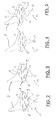
figures 2 through 5 show several cross-sectional views of a wiper blade as used in a windscreen wiper device offigure 1 . -
Figure 1 shows a preferred variant of a windscreen wiper device 1 according to the invention. Said windscreen wiper device is built up of anelastomeric wiper blade 2 comprising a central or middle longitudinal groove 3, wherein a central or middle longitudinal strip 4 made of spring band steel is fitted in said longitudinal groove 3 (seefigures 2 through 5 ). Said strip 4 forms a flexible carrier element for therubber wiper blade 2, as it were, which is thus biassed in a curved position (the curvature in operative position being that of a windscreen to be wiped). An end of said strip 4 and/or an end of saidwiperblade 2 is connected on either side of the windscreen wiper device 1 to respective connecting pieces or "end caps" 5. In this embodiment, the connecting pieces 5 are separate constructional elements, which may be form-locked, as well as force-locked to both ends of said strip/4 said wiper blade. In another preferred variant, said connecting pieces 5 are in one piece with the strip 4 made of spring band steel. The windscreen wiper device 1 is furthermore built up of a connecting device 6 for connecting an oscillatingwiper arm 7 thereto. The oscillatingwiper arm 7 is pivotally connected to the connecting device 6 about a pivot axis near one end. The preferred embodiment offigure 1 according to the invention comprises a spoiler or "air deflector" 8 which is made in one piece with therubber wiper blade 2 and which extends along the entire length thereof. The connecting device 6 with thewiper blade 2 is mounted onto the oscillatingarm 7 as follows. A joint part 9 being already clipped onto the connecting device 6 is pivoted relative to the connecting device 6, so that said joint part 9 can be easily slided on a free end of the oscillatingarm 7. During this sliding movement aresilient tongue 10 of said joint part 9 is initially pushed in against a spring force and then allowed to spring back into said hole 11 of said oscillatingarm 7, thus snapping, that is clipping theresilient tongue 10 into the hole 11. This is a so-called bayonet-connection. The oscillatingarm 7 together with the joint part 9 may then be pivoted back in a position parallel to thewiper blade 2 in order to be ready for use. By subsequently pushing in again saidresilient tongue 10 against the spring force (as if it were a push button), the connecting device 6 and the joint part 9 together with thewiper blade 2 may be released from the oscillatingarm 7. Dismounting the connecting device 6 with thewiper blade 2 from the oscillatingarm 7 is thus realized by sliding the connecting device 6 and the joint part 9 together with thewiper blade 2 in a direction away from the oscillatingarm 7. The connecting device 6 comprises twocylindrical protrusions 12 extending outwards on either side of said connecting device 6. Theseprotrusions 12 pivotally engage in identically shapedcylindrical recesses 13 of the plastic joint part 9. Saidprotrusions 12 act as bearing surfaces at the location of the pivot axis in order to pivot the joint part 9 (and the oscillatingarm 7 attached thereto) about the pivot axis near one end of the oscillatingarm 7. - Although not shown in
figure 1 , but fully understood by a skilled person, said oscillatingarm 7 is connected to a mounting head fixed for rotation to a shaft driven by a small motor. In use, the shaft rotates alternately in a clockwise and in a counter-clockwise sense carrying the mounting head into rotation also, which in turn draws said oscillatingarm 7 into rotation and by means of said connecting device 6 moves saidwiper blade 2. - With reference to
figures 2 through 5 thewiper blade 2 comprises awiping element 14. Saidwiping element 14 consists of two tiltingweb grooves 15 defining a strip-like tiltingweb 16 between them, as well as a downwardly extending wiping lip 17 on the tiltingweb 16. Said wiping lip 17 rests with its free end on a windscreen to be wiped. In action said wiping lip 17, as if it were a hinge, tilts in its oscillation reversal positions. -
Figures 2 and 3 refer to a cross-sectional view of thewiper blade 2 in case a relatively low pressure is exerted by the oscillatingarm 7, that is the longitudinal strip 4 on thewiper blade 2. The magnitude of said pressure is dependent, magnitude of said pressure is dependent, for example, on the curvature of a windscreen to be wiped, the curvature of the longitudinal strip 4, as well as on the force of a spring mounted between the mounting head and the oscillatingarm 7. Thewiping element 14 is in that case in a first position facing away from the longitudinal strip 4 (seefigure 2 ). Thewiping element 14 is allowed to follow its normal oscillatory movement (seefigure 3 ). - As can be seen in
figures 2 through 5 , the central groove 3 extends in downward direction beneath the longitudinal strip 4 for forming a longitudinalhollow channel 18 defined by said longitudinal strip 4 and abottom 19 of said groove 3. The cross-sectional view of thewiper blade 2, as shown infigures 4 and 5 , refers to a situation when a relatively high pressure is exerted by the longitudinal strip 4 on thewiper blade 2. In that particular case saidwiping element 14 is forced into a second position facing towards the longitudinal strip 4 (seefigure 4 ). In other words, due to the resiliency of thebottom 19 of the groove 3, saidwiping element 14 is allowed to move in a direction perpendicular to a windscreen to be wiped, dependent on the pressure exerted by the longitudinal strip 4 on thewiper blade 2, that is a relatively low pressure A infigures 2 and 3 , as well as a relatively high pressure B infigures 4 and 5 . In said second position of said wiping element 14 (seefigures 4 and 5 ) saidbottom 19 is provided withstop surfaces 20 on opposite sides of saidwiping element 14 to limit the oscillatory movement of saidwiping element 14 in said second position. - Said central groove 3 also extends in upward direction above the longitudinal strip 4 for forming a longitinal
hollow channel 21 defined by said longitudinal strip 4 and anupper surface 22 of said groove 3. This is realized for facilitating insertion of said longitudinal strip 4 inside said groove 3 and for reducing the amount of raw material used in order to minimize costs and weight. - The invention is not restricted to the variants shown in the drawing, but it also extends to other preferred embodiments that fall within the scope of the appended claims.
Claims (8)
- A windscreen wiper device (1) comprising an elastic, elongated carrier element, as well as an elongated wiper blade (2) of a flexible material, said wiper blade (2) comprising a wiping element (14) which can be placed in abutment with a windscreen to be wiped, which wiper blade (2) includes a central longitudinal groove (3), in which groove (3) a longitudinal strip (4) of the carrier element is disposed, which windscreen wiper device (1) comprises a connecting device (6) for an oscillating arm (7), wherein said oscillating arm (7) is pivotally connected to said connecting device (6) about a pivot axis near one end thereof, characterized in that said wiping element (14) is movable in a direction at least substantially perpendicular to a windscreen to be wiped, dependent on the pressure exerted by the longitudinal strip (4) on the wiper blade (2).
- A windscreen wiper device (1) according to claim 1, wherein said wiping element (14) is resilient between a first position facing away from the longitudinal strip (4) and a second position facing towards the longitudinal strip (4).
- A windscreen wiper device (1) according to claim 2, wherein said wiping element (14) is in said first position at a pressure A exerted by the longitudinal strip (4) on the wiper blade (2), wherein said wiping element is in said second position at a pressure B exerted by the longitudinal strip (4) on the wiper blade (2), and wherein pressure A is smaller than pressure B.
- A windscreen wiper device (1) according to any of the preceding claims 1 through 4, wherein said groove (3) extends in downward direction beneath the longitudinal strip (4) for forming a longitinal hollow channel (18) defined by said longitudinal strip (4) and a bottom (19) of said groove (3).
- A windscreen wiper device (1) according to claim 4, wherein said bottom (19) is flexible.
- A windscreen wiper device (1) according to claim 5, wherein said bottom (19) is provided with stop surfaces (20) on opposite sides of said wiping element (14), and wherein said stop surfaces (20) limit an oscillatory movement of said wiping element (14) in said second position.
- A windscreen wiper device (1) according to any of the preceding claims 1 through 6, wherein said groove (3) extends in upward direction above the longitudinal strip (4) for forming a longitinal hollow channel (21) defined by said longitudinal strip (4) and an upper surface (22) of said groove (3).
- A windscreen wiper device (1) according to any of the preceding claims 1 through 7, wherein said wiper blade (2) is provided with a spoiler (8) at a side thereof facing away from a windscreen to be wiped.
Priority Applications (8)
| Application Number | Priority Date | Filing Date | Title |
|---|---|---|---|
| EP09156718.0A EP2236364B1 (en) | 2009-03-30 | 2009-03-30 | Windscreen wiper device |
| ES09156718.0T ES2452468T3 (en) | 2009-03-30 | 2009-03-30 | Windshield wiper device |
| PL09156718T PL2236364T3 (en) | 2009-03-30 | 2009-03-30 | Windscreen wiper device |
| SI200930859T SI2236364T1 (en) | 2009-03-30 | 2009-03-30 | Windscreen wiper device |
| JP2010057951A JP5765723B2 (en) | 2009-03-30 | 2010-03-15 | Windshield wiper device |
| US12/727,683 US8327499B2 (en) | 2009-03-30 | 2010-03-19 | Windscreen wiper device |
| KR1020100025258A KR101715396B1 (en) | 2009-03-30 | 2010-03-22 | Windscreen wiper device |
| CN201010134478.5A CN101966844B (en) | 2009-03-30 | 2010-03-29 | Windscreen wiper device |
Applications Claiming Priority (1)
| Application Number | Priority Date | Filing Date | Title |
|---|---|---|---|
| EP09156718.0A EP2236364B1 (en) | 2009-03-30 | 2009-03-30 | Windscreen wiper device |
Publications (2)
| Publication Number | Publication Date |
|---|---|
| EP2236364A1 true EP2236364A1 (en) | 2010-10-06 |
| EP2236364B1 EP2236364B1 (en) | 2013-12-11 |
Family
ID=40972903
Family Applications (1)
| Application Number | Title | Priority Date | Filing Date |
|---|---|---|---|
| EP09156718.0A Active EP2236364B1 (en) | 2009-03-30 | 2009-03-30 | Windscreen wiper device |
Country Status (8)
| Country | Link |
|---|---|
| US (1) | US8327499B2 (en) |
| EP (1) | EP2236364B1 (en) |
| JP (1) | JP5765723B2 (en) |
| KR (1) | KR101715396B1 (en) |
| CN (1) | CN101966844B (en) |
| ES (1) | ES2452468T3 (en) |
| PL (1) | PL2236364T3 (en) |
| SI (1) | SI2236364T1 (en) |
Cited By (11)
| Publication number | Priority date | Publication date | Assignee | Title |
|---|---|---|---|---|
| WO2013060364A1 (en) * | 2011-10-26 | 2013-05-02 | Federal-Mogul S.A. | Windscreen wiper device |
| WO2017220122A1 (en) * | 2016-06-20 | 2017-12-28 | Federal-Mogul S.A. | A windscreen wiper device of the flat blade type |
| US9889822B2 (en) | 2014-03-07 | 2018-02-13 | Pylon Manufacturing Corp. | Windshield wiper connector and assembly |
| US10005431B2 (en) | 2011-04-21 | 2018-06-26 | Pylon Manufacturing Corp. | Vortex damping wiper blade |
| US10077026B2 (en) | 2012-02-24 | 2018-09-18 | Pylon Manufacturing Corp. | Wiper blade |
| US10166951B2 (en) | 2013-03-15 | 2019-01-01 | Pylon Manufacturing Corp. | Windshield wiper connector |
| US10189445B2 (en) | 2012-02-24 | 2019-01-29 | Pylon Manufacturing Corp. | Wiper blade |
| US10457252B2 (en) | 2011-07-28 | 2019-10-29 | Pylon Manufacturing Corp. | Windshield wiper adapter, connector and assembly |
| US10464533B2 (en) | 2011-04-21 | 2019-11-05 | Pylon Manufacturing Corp. | Wiper blade with cover |
| US10597004B2 (en) | 2011-07-29 | 2020-03-24 | Pylon Manufacturing Corporation | Windshield wiper connector |
| US10829092B2 (en) | 2012-09-24 | 2020-11-10 | Pylon Manufacturing Corp. | Wiper blade with modular mounting base |
Families Citing this family (9)
| Publication number | Priority date | Publication date | Assignee | Title |
|---|---|---|---|---|
| WO2010024560A2 (en) * | 2008-08-25 | 2010-03-04 | 주식회사 캐프 | Flat vehicular wiper with hydraulic shock-absorbing unit |
| DE102010039526A1 (en) * | 2010-08-19 | 2012-02-23 | Robert Bosch Gmbh | wiper arm |
| JP2014530788A (en) * | 2011-10-26 | 2014-11-20 | フェデラル−モグル エス.エー.Federal−Mogul.S.A. | Windshield wiper device |
| KR20150037849A (en) * | 2012-08-02 | 2015-04-08 | 페더랄-모굴 에스.아. | Windscreen Wiper Device |
| KR101484062B1 (en) * | 2013-06-10 | 2015-01-20 | 케이씨더블류 주식회사 | Flat wiper blade |
| US10150452B2 (en) | 2016-10-14 | 2018-12-11 | Federal-Mogul Motorparts Llc | Windscreen wiper device |
| CN108238008B (en) * | 2018-02-12 | 2024-04-26 | 博世汽车部件(长春)有限公司 | Wiper and wiper arm thereof |
| KR20220114901A (en) * | 2021-02-09 | 2022-08-17 | 주식회사 캐프 | Wiper device |
| EP4480762A1 (en) * | 2023-06-19 | 2024-12-25 | Valeo Systèmes d'Essuyage | Wiper blade for a motor vehicle |
Citations (5)
| Publication number | Priority date | Publication date | Assignee | Title |
|---|---|---|---|---|
| GB2005532A (en) * | 1977-10-13 | 1979-04-25 | Aguiari O | Windscreen wiper |
| DE19827032A1 (en) * | 1997-06-18 | 1998-12-24 | Asmo Co Ltd | Windscreen wiper blade rubber |
| DE19745006A1 (en) | 1997-10-11 | 1999-04-22 | Bosch Gmbh Robert | Wiper system, especially for windscreens of motor vehicles |
| DE102005054142A1 (en) * | 2005-11-14 | 2007-05-16 | Bosch Gmbh Robert | squeegee |
| EP1964733A1 (en) * | 2007-02-27 | 2008-09-03 | Giovanni Creaco | Wiper blade of a windscreen wiper for motor vehicles |
Family Cites Families (14)
| Publication number | Priority date | Publication date | Assignee | Title |
|---|---|---|---|---|
| US3116510A (en) * | 1963-05-20 | 1964-01-07 | Trico Products Corp | Windshield wiper |
| DE1430623C3 (en) * | 1964-06-13 | 1975-04-24 | Robert Bosch Gmbh, 7000 Stuttgart | Wiper blades for vehicles |
| US3636583A (en) * | 1970-01-26 | 1972-01-25 | Ian K Rosen | Squeegee blade |
| JPH02162142A (en) | 1988-12-15 | 1990-06-21 | Nissan Motor Co Ltd | Wiper blade driver |
| CA2118874C (en) * | 1993-03-12 | 2001-05-29 | Tadao Kushida | Vehicle windshield wiper blade assembly and wiper system |
| KR19980063590A (en) * | 1996-12-18 | 1998-10-07 | 김덕수 | Car Windshield Wiper |
| DE10120467A1 (en) * | 2001-04-26 | 2002-10-31 | Bosch Gmbh Robert | Wiper blade for cleaning windows, especially of motor vehicles |
| FR2884205B1 (en) * | 2005-04-08 | 2007-05-18 | Peugeot Citroen Automobiles Sa | PERFECTED WINDSCREEN WIPER AND WINDSCREEN WIPER WITH SUCH RACLETTE |
| KR101138261B1 (en) | 2005-06-29 | 2012-04-24 | 엘지디스플레이 주식회사 | liquid crystal display device |
| US20070022556A1 (en) * | 2005-07-28 | 2007-02-01 | Walworth Van T | Wind deflector with symmetrical geometry |
| US7861363B2 (en) | 2006-02-02 | 2011-01-04 | Trico Products Corporation | Beam blade windshield wiper assembly having an airfoil |
| US20080150193A1 (en) | 2006-12-15 | 2008-06-26 | Walworth Van T | Method of manufacture of a molded hollow using tangential structures |
| DE102007056321A1 (en) | 2007-11-22 | 2009-11-26 | Robert Bosch Gmbh | wiper blade |
| KR101592627B1 (en) * | 2009-04-27 | 2016-02-05 | 페더랄-모굴 에스.아. | Windscreen wiper device |
-
2009
- 2009-03-30 ES ES09156718.0T patent/ES2452468T3/en active Active
- 2009-03-30 PL PL09156718T patent/PL2236364T3/en unknown
- 2009-03-30 EP EP09156718.0A patent/EP2236364B1/en active Active
- 2009-03-30 SI SI200930859T patent/SI2236364T1/en unknown
-
2010
- 2010-03-15 JP JP2010057951A patent/JP5765723B2/en not_active Expired - Fee Related
- 2010-03-19 US US12/727,683 patent/US8327499B2/en active Active
- 2010-03-22 KR KR1020100025258A patent/KR101715396B1/en not_active Expired - Fee Related
- 2010-03-29 CN CN201010134478.5A patent/CN101966844B/en not_active Expired - Fee Related
Patent Citations (5)
| Publication number | Priority date | Publication date | Assignee | Title |
|---|---|---|---|---|
| GB2005532A (en) * | 1977-10-13 | 1979-04-25 | Aguiari O | Windscreen wiper |
| DE19827032A1 (en) * | 1997-06-18 | 1998-12-24 | Asmo Co Ltd | Windscreen wiper blade rubber |
| DE19745006A1 (en) | 1997-10-11 | 1999-04-22 | Bosch Gmbh Robert | Wiper system, especially for windscreens of motor vehicles |
| DE102005054142A1 (en) * | 2005-11-14 | 2007-05-16 | Bosch Gmbh Robert | squeegee |
| EP1964733A1 (en) * | 2007-02-27 | 2008-09-03 | Giovanni Creaco | Wiper blade of a windscreen wiper for motor vehicles |
Cited By (17)
| Publication number | Priority date | Publication date | Assignee | Title |
|---|---|---|---|---|
| US10543813B2 (en) | 2010-02-10 | 2020-01-28 | Pylon Manufacturing Corp. | Wiper blade |
| US11124158B2 (en) | 2011-04-21 | 2021-09-21 | Pylon Manufacturing Corp. | Wiper blade with cover |
| US10005431B2 (en) | 2011-04-21 | 2018-06-26 | Pylon Manufacturing Corp. | Vortex damping wiper blade |
| US10464533B2 (en) | 2011-04-21 | 2019-11-05 | Pylon Manufacturing Corp. | Wiper blade with cover |
| US10457252B2 (en) | 2011-07-28 | 2019-10-29 | Pylon Manufacturing Corp. | Windshield wiper adapter, connector and assembly |
| US10597004B2 (en) | 2011-07-29 | 2020-03-24 | Pylon Manufacturing Corporation | Windshield wiper connector |
| RU2566596C1 (en) * | 2011-10-26 | 2015-10-27 | Федерал-Моугал С.А. | Device of windshield wiper |
| US9623842B2 (en) | 2011-10-26 | 2017-04-18 | Federal-Mogul S.A. | Windscreen wiper device |
| WO2013060364A1 (en) * | 2011-10-26 | 2013-05-02 | Federal-Mogul S.A. | Windscreen wiper device |
| US10189445B2 (en) | 2012-02-24 | 2019-01-29 | Pylon Manufacturing Corp. | Wiper blade |
| US10077026B2 (en) | 2012-02-24 | 2018-09-18 | Pylon Manufacturing Corp. | Wiper blade |
| US11136002B2 (en) | 2012-02-24 | 2021-10-05 | Pylon Manufacturing Corp. | Wiper blade |
| US11180118B2 (en) | 2012-02-24 | 2021-11-23 | Pylon Manufacturing Corp. | Wiper blade |
| US10829092B2 (en) | 2012-09-24 | 2020-11-10 | Pylon Manufacturing Corp. | Wiper blade with modular mounting base |
| US10166951B2 (en) | 2013-03-15 | 2019-01-01 | Pylon Manufacturing Corp. | Windshield wiper connector |
| US9889822B2 (en) | 2014-03-07 | 2018-02-13 | Pylon Manufacturing Corp. | Windshield wiper connector and assembly |
| WO2017220122A1 (en) * | 2016-06-20 | 2017-12-28 | Federal-Mogul S.A. | A windscreen wiper device of the flat blade type |
Also Published As
| Publication number | Publication date |
|---|---|
| ES2452468T3 (en) | 2014-04-01 |
| US20100251501A1 (en) | 2010-10-07 |
| CN101966844A (en) | 2011-02-09 |
| EP2236364B1 (en) | 2013-12-11 |
| KR101715396B1 (en) | 2017-03-22 |
| CN101966844B (en) | 2015-05-27 |
| JP2010235112A (en) | 2010-10-21 |
| PL2236364T3 (en) | 2014-05-30 |
| KR20100109398A (en) | 2010-10-08 |
| SI2236364T1 (en) | 2014-04-30 |
| US8327499B2 (en) | 2012-12-11 |
| JP5765723B2 (en) | 2015-08-19 |
Similar Documents
| Publication | Publication Date | Title |
|---|---|---|
| EP2236364B1 (en) | Windscreen wiper device | |
| EP2236366A1 (en) | Windscreen wiper device | |
| EP2424754B1 (en) | Windscreen wiper device | |
| EP2991862B1 (en) | A windscreen wiper device | |
| EP2105362B2 (en) | Wiper blade | |
| EP3472004B1 (en) | A windscreen wiper device of the flat blade type | |
| EP2621773B1 (en) | A windscreen wiper device | |
| US9545897B2 (en) | Windscreen wiper device | |
| EP2493731A1 (en) | Windscreen wiper device | |
| WO2011000403A1 (en) | Windscreen wiper device | |
| EP3580099B1 (en) | Windscreen wiper device | |
| EP2771214B1 (en) | Windscreen wiper device | |
| EP2585344B1 (en) | A windscreen wiper device | |
| JP2014530788A (en) | Windshield wiper device |
Legal Events
| Date | Code | Title | Description |
|---|---|---|---|
| PUAI | Public reference made under article 153(3) epc to a published international application that has entered the european phase |
Free format text: ORIGINAL CODE: 0009012 |
|
| AK | Designated contracting states |
Kind code of ref document: A1 Designated state(s): AT BE BG CH CY CZ DE DK EE ES FI FR GB GR HR HU IE IS IT LI LT LU LV MC MK MT NL NO PL PT RO SE SI SK TR |
|
| AX | Request for extension of the european patent |
Extension state: AL BA RS |
|
| 17P | Request for examination filed |
Effective date: 20110328 |
|
| 17Q | First examination report despatched |
Effective date: 20110512 |
|
| AKX | Designation fees paid |
Designated state(s): AT BE BG CH CY CZ DE DK EE ES FI FR GB GR HR HU IE IS IT LI LT LU LV MC MK MT NL NO PL PT RO SE SI SK TR |
|
| GRAP | Despatch of communication of intention to grant a patent |
Free format text: ORIGINAL CODE: EPIDOSNIGR1 |
|
| INTG | Intention to grant announced |
Effective date: 20130705 |
|
| GRAS | Grant fee paid |
Free format text: ORIGINAL CODE: EPIDOSNIGR3 |
|
| GRAA | (expected) grant |
Free format text: ORIGINAL CODE: 0009210 |
|
| AK | Designated contracting states |
Kind code of ref document: B1 Designated state(s): AT BE BG CH CY CZ DE DK EE ES FI FR GB GR HR HU IE IS IT LI LT LU LV MC MK MT NL NO PL PT RO SE SI SK TR |
|
| REG | Reference to a national code |
Ref country code: GB Ref legal event code: FG4D |
|
| REG | Reference to a national code |
Ref country code: CH Ref legal event code: EP |
|
| REG | Reference to a national code |
Ref country code: AT Ref legal event code: REF Ref document number: 644359 Country of ref document: AT Kind code of ref document: T Effective date: 20140115 |
|
| REG | Reference to a national code |
Ref country code: IE Ref legal event code: FG4D |
|
| REG | Reference to a national code |
Ref country code: DE Ref legal event code: R096 Ref document number: 602009020618 Country of ref document: DE Effective date: 20140206 |
|
| REG | Reference to a national code |
Ref country code: RO Ref legal event code: EPE |
|
| REG | Reference to a national code |
Ref country code: NL Ref legal event code: T3 |
|
| REG | Reference to a national code |
Ref country code: SE Ref legal event code: TRGR |
|
| REG | Reference to a national code |
Ref country code: ES Ref legal event code: FG2A Ref document number: 2452468 Country of ref document: ES Kind code of ref document: T3 Effective date: 20140401 |
|
| REG | Reference to a national code |
Ref country code: AT Ref legal event code: MK05 Ref document number: 644359 Country of ref document: AT Kind code of ref document: T Effective date: 20131211 |
|
| PG25 | Lapsed in a contracting state [announced via postgrant information from national office to epo] |
Ref country code: HR Free format text: LAPSE BECAUSE OF FAILURE TO SUBMIT A TRANSLATION OF THE DESCRIPTION OR TO PAY THE FEE WITHIN THE PRESCRIBED TIME-LIMIT Effective date: 20131211 Ref country code: LT Free format text: LAPSE BECAUSE OF FAILURE TO SUBMIT A TRANSLATION OF THE DESCRIPTION OR TO PAY THE FEE WITHIN THE PRESCRIBED TIME-LIMIT Effective date: 20131211 Ref country code: NO Free format text: LAPSE BECAUSE OF FAILURE TO SUBMIT A TRANSLATION OF THE DESCRIPTION OR TO PAY THE FEE WITHIN THE PRESCRIBED TIME-LIMIT Effective date: 20140311 Ref country code: FI Free format text: LAPSE BECAUSE OF FAILURE TO SUBMIT A TRANSLATION OF THE DESCRIPTION OR TO PAY THE FEE WITHIN THE PRESCRIBED TIME-LIMIT Effective date: 20131211 |
|
| REG | Reference to a national code |
Ref country code: LT Ref legal event code: MG4D |
|
| PG25 | Lapsed in a contracting state [announced via postgrant information from national office to epo] |
Ref country code: CY Free format text: LAPSE BECAUSE OF FAILURE TO SUBMIT A TRANSLATION OF THE DESCRIPTION OR TO PAY THE FEE WITHIN THE PRESCRIBED TIME-LIMIT Effective date: 20131211 Ref country code: AT Free format text: LAPSE BECAUSE OF FAILURE TO SUBMIT A TRANSLATION OF THE DESCRIPTION OR TO PAY THE FEE WITHIN THE PRESCRIBED TIME-LIMIT Effective date: 20131211 Ref country code: LV Free format text: LAPSE BECAUSE OF FAILURE TO SUBMIT A TRANSLATION OF THE DESCRIPTION OR TO PAY THE FEE WITHIN THE PRESCRIBED TIME-LIMIT Effective date: 20131211 |
|
| REG | Reference to a national code |
Ref country code: PL Ref legal event code: T3 |
|
| REG | Reference to a national code |
Ref country code: SK Ref legal event code: T3 Ref document number: E 15920 Country of ref document: SK |
|
| PG25 | Lapsed in a contracting state [announced via postgrant information from national office to epo] |
Ref country code: IS Free format text: LAPSE BECAUSE OF FAILURE TO SUBMIT A TRANSLATION OF THE DESCRIPTION OR TO PAY THE FEE WITHIN THE PRESCRIBED TIME-LIMIT Effective date: 20140411 Ref country code: EE Free format text: LAPSE BECAUSE OF FAILURE TO SUBMIT A TRANSLATION OF THE DESCRIPTION OR TO PAY THE FEE WITHIN THE PRESCRIBED TIME-LIMIT Effective date: 20131211 |
|
| PG25 | Lapsed in a contracting state [announced via postgrant information from national office to epo] |
Ref country code: PT Free format text: LAPSE BECAUSE OF FAILURE TO SUBMIT A TRANSLATION OF THE DESCRIPTION OR TO PAY THE FEE WITHIN THE PRESCRIBED TIME-LIMIT Effective date: 20140411 |
|
| REG | Reference to a national code |
Ref country code: DE Ref legal event code: R026 Ref document number: 602009020618 Country of ref document: DE |
|
| PLBI | Opposition filed |
Free format text: ORIGINAL CODE: 0009260 |
|
| PLAB | Opposition data, opponent's data or that of the opponent's representative modified |
Free format text: ORIGINAL CODE: 0009299OPPO |
|
| REG | Reference to a national code |
Ref country code: HU Ref legal event code: AG4A Ref document number: E020498 Country of ref document: HU |
|
| 26 | Opposition filed |
Opponent name: VALEO SYSTEMES D'ESSUYAGE Effective date: 20140910 |
|
| PLAX | Notice of opposition and request to file observation + time limit sent |
Free format text: ORIGINAL CODE: EPIDOSNOBS2 |
|
| R26 | Opposition filed (corrected) |
Opponent name: VALEO SYSTEMES D'ESSUYAGE Effective date: 20140910 |
|
| PG25 | Lapsed in a contracting state [announced via postgrant information from national office to epo] |
Ref country code: DK Free format text: LAPSE BECAUSE OF FAILURE TO SUBMIT A TRANSLATION OF THE DESCRIPTION OR TO PAY THE FEE WITHIN THE PRESCRIBED TIME-LIMIT Effective date: 20131211 Ref country code: LU Free format text: LAPSE BECAUSE OF FAILURE TO SUBMIT A TRANSLATION OF THE DESCRIPTION OR TO PAY THE FEE WITHIN THE PRESCRIBED TIME-LIMIT Effective date: 20140330 |
|
| REG | Reference to a national code |
Ref country code: CH Ref legal event code: PL |
|
| REG | Reference to a national code |
Ref country code: DE Ref legal event code: R026 Ref document number: 602009020618 Country of ref document: DE Effective date: 20140910 |
|
| REG | Reference to a national code |
Ref country code: IE Ref legal event code: MM4A |
|
| PG25 | Lapsed in a contracting state [announced via postgrant information from national office to epo] |
Ref country code: CH Free format text: LAPSE BECAUSE OF NON-PAYMENT OF DUE FEES Effective date: 20140331 Ref country code: LI Free format text: LAPSE BECAUSE OF NON-PAYMENT OF DUE FEES Effective date: 20140331 Ref country code: IE Free format text: LAPSE BECAUSE OF NON-PAYMENT OF DUE FEES Effective date: 20140330 |
|
| PLAF | Information modified related to communication of a notice of opposition and request to file observations + time limit |
Free format text: ORIGINAL CODE: EPIDOSCOBS2 |
|
| PLBB | Reply of patent proprietor to notice(s) of opposition received |
Free format text: ORIGINAL CODE: EPIDOSNOBS3 |
|
| REG | Reference to a national code |
Ref country code: FR Ref legal event code: PLFP Year of fee payment: 8 |
|
| PG25 | Lapsed in a contracting state [announced via postgrant information from national office to epo] |
Ref country code: MT Free format text: LAPSE BECAUSE OF FAILURE TO SUBMIT A TRANSLATION OF THE DESCRIPTION OR TO PAY THE FEE WITHIN THE PRESCRIBED TIME-LIMIT Effective date: 20131211 |
|
| PG25 | Lapsed in a contracting state [announced via postgrant information from national office to epo] |
Ref country code: MC Free format text: LAPSE BECAUSE OF FAILURE TO SUBMIT A TRANSLATION OF THE DESCRIPTION OR TO PAY THE FEE WITHIN THE PRESCRIBED TIME-LIMIT Effective date: 20131211 |
|
| PGFP | Annual fee paid to national office [announced via postgrant information from national office to epo] |
Ref country code: RO Payment date: 20160229 Year of fee payment: 8 |
|
| PLCK | Communication despatched that opposition was rejected |
Free format text: ORIGINAL CODE: EPIDOSNREJ1 |
|
| PG25 | Lapsed in a contracting state [announced via postgrant information from national office to epo] |
Ref country code: BG Free format text: LAPSE BECAUSE OF FAILURE TO SUBMIT A TRANSLATION OF THE DESCRIPTION OR TO PAY THE FEE WITHIN THE PRESCRIBED TIME-LIMIT Effective date: 20131211 Ref country code: GR Free format text: LAPSE BECAUSE OF FAILURE TO SUBMIT A TRANSLATION OF THE DESCRIPTION OR TO PAY THE FEE WITHIN THE PRESCRIBED TIME-LIMIT Effective date: 20140312 |
|
| APAH | Appeal reference modified |
Free format text: ORIGINAL CODE: EPIDOSCREFNO |
|
| APBM | Appeal reference recorded |
Free format text: ORIGINAL CODE: EPIDOSNREFNO |
|
| APBP | Date of receipt of notice of appeal recorded |
Free format text: ORIGINAL CODE: EPIDOSNNOA2O |
|
| APBQ | Date of receipt of statement of grounds of appeal recorded |
Free format text: ORIGINAL CODE: EPIDOSNNOA3O |
|
| REG | Reference to a national code |
Ref country code: FR Ref legal event code: PLFP Year of fee payment: 9 |
|
| PGFP | Annual fee paid to national office [announced via postgrant information from national office to epo] |
Ref country code: SE Payment date: 20170307 Year of fee payment: 9 Ref country code: NL Payment date: 20170309 Year of fee payment: 9 |
|
| PGFP | Annual fee paid to national office [announced via postgrant information from national office to epo] |
Ref country code: HU Payment date: 20170223 Year of fee payment: 9 Ref country code: SI Payment date: 20170317 Year of fee payment: 9 Ref country code: SK Payment date: 20170227 Year of fee payment: 9 Ref country code: GB Payment date: 20170223 Year of fee payment: 9 |
|
| PGFP | Annual fee paid to national office [announced via postgrant information from national office to epo] |
Ref country code: ES Payment date: 20170308 Year of fee payment: 9 |
|
| PG25 | Lapsed in a contracting state [announced via postgrant information from national office to epo] |
Ref country code: RO Free format text: LAPSE BECAUSE OF NON-PAYMENT OF DUE FEES Effective date: 20170330 |
|
| REG | Reference to a national code |
Ref country code: FR Ref legal event code: PLFP Year of fee payment: 10 |
|
| PG25 | Lapsed in a contracting state [announced via postgrant information from national office to epo] |
Ref country code: MK Free format text: LAPSE BECAUSE OF FAILURE TO SUBMIT A TRANSLATION OF THE DESCRIPTION OR TO PAY THE FEE WITHIN THE PRESCRIBED TIME-LIMIT Effective date: 20131211 |
|
| PG25 | Lapsed in a contracting state [announced via postgrant information from national office to epo] |
Ref country code: SE Free format text: LAPSE BECAUSE OF NON-PAYMENT OF DUE FEES Effective date: 20180331 |
|
| REG | Reference to a national code |
Ref country code: NL Ref legal event code: MM Effective date: 20180401 |
|
| GBPC | Gb: european patent ceased through non-payment of renewal fee |
Effective date: 20180330 |
|
| REG | Reference to a national code |
Ref country code: SK Ref legal event code: MM4A Ref document number: E 15920 Country of ref document: SK Effective date: 20180330 |
|
| PG25 | Lapsed in a contracting state [announced via postgrant information from national office to epo] |
Ref country code: NL Free format text: LAPSE BECAUSE OF NON-PAYMENT OF DUE FEES Effective date: 20180401 |
|
| REG | Reference to a national code |
Ref country code: SI Ref legal event code: KO00 Effective date: 20181105 |
|
| PG25 | Lapsed in a contracting state [announced via postgrant information from national office to epo] |
Ref country code: HU Free format text: LAPSE BECAUSE OF NON-PAYMENT OF DUE FEES Effective date: 20180331 Ref country code: SK Free format text: LAPSE BECAUSE OF NON-PAYMENT OF DUE FEES Effective date: 20180330 |
|
| PG25 | Lapsed in a contracting state [announced via postgrant information from national office to epo] |
Ref country code: GB Free format text: LAPSE BECAUSE OF NON-PAYMENT OF DUE FEES Effective date: 20180330 Ref country code: SI Free format text: LAPSE BECAUSE OF NON-PAYMENT OF DUE FEES Effective date: 20180331 |
|
| REG | Reference to a national code |
Ref country code: ES Ref legal event code: FD2A Effective date: 20190911 |
|
| REG | Reference to a national code |
Ref country code: DE Ref legal event code: R100 Ref document number: 602009020618 Country of ref document: DE |
|
| APBU | Appeal procedure closed |
Free format text: ORIGINAL CODE: EPIDOSNNOA9O |
|
| PG25 | Lapsed in a contracting state [announced via postgrant information from national office to epo] |
Ref country code: ES Free format text: LAPSE BECAUSE OF NON-PAYMENT OF DUE FEES Effective date: 20180331 |
|
| PLBN | Opposition rejected |
Free format text: ORIGINAL CODE: 0009273 |
|
| STAA | Information on the status of an ep patent application or granted ep patent |
Free format text: STATUS: OPPOSITION REJECTED |
|
| 27O | Opposition rejected |
Effective date: 20190913 |
|
| PGFP | Annual fee paid to national office [announced via postgrant information from national office to epo] |
Ref country code: IT Payment date: 20200221 Year of fee payment: 12 |
|
| PGFP | Annual fee paid to national office [announced via postgrant information from national office to epo] |
Ref country code: BE Payment date: 20200217 Year of fee payment: 12 Ref country code: CZ Payment date: 20200320 Year of fee payment: 12 |
|
| PGFP | Annual fee paid to national office [announced via postgrant information from national office to epo] |
Ref country code: FR Payment date: 20200214 Year of fee payment: 12 Ref country code: TR Payment date: 20200330 Year of fee payment: 12 |
|
| PGFP | Annual fee paid to national office [announced via postgrant information from national office to epo] |
Ref country code: PL Payment date: 20200326 Year of fee payment: 12 |
|
| PG25 | Lapsed in a contracting state [announced via postgrant information from national office to epo] |
Ref country code: CZ Free format text: LAPSE BECAUSE OF NON-PAYMENT OF DUE FEES Effective date: 20210330 |
|
| REG | Reference to a national code |
Ref country code: BE Ref legal event code: MM Effective date: 20210331 |
|
| PG25 | Lapsed in a contracting state [announced via postgrant information from national office to epo] |
Ref country code: FR Free format text: LAPSE BECAUSE OF NON-PAYMENT OF DUE FEES Effective date: 20210331 |
|
| PG25 | Lapsed in a contracting state [announced via postgrant information from national office to epo] |
Ref country code: IT Free format text: LAPSE BECAUSE OF NON-PAYMENT OF DUE FEES Effective date: 20210330 |
|
| PG25 | Lapsed in a contracting state [announced via postgrant information from national office to epo] |
Ref country code: BE Free format text: LAPSE BECAUSE OF NON-PAYMENT OF DUE FEES Effective date: 20210331 |
|
| PG25 | Lapsed in a contracting state [announced via postgrant information from national office to epo] |
Ref country code: PL Free format text: LAPSE BECAUSE OF NON-PAYMENT OF DUE FEES Effective date: 20210330 |
|
| PG25 | Lapsed in a contracting state [announced via postgrant information from national office to epo] |
Ref country code: TR Free format text: LAPSE BECAUSE OF NON-PAYMENT OF DUE FEES Effective date: 20210330 |
|
| PGFP | Annual fee paid to national office [announced via postgrant information from national office to epo] |
Ref country code: DE Payment date: 20260327 Year of fee payment: 18 |