EP2236235B1 - A high temperature additive manufacturing system for making near net shape airfoil leading edge protection with a cladded mandrel - Google Patents
A high temperature additive manufacturing system for making near net shape airfoil leading edge protection with a cladded mandrel Download PDFInfo
- Publication number
- EP2236235B1 EP2236235B1 EP20100157403 EP10157403A EP2236235B1 EP 2236235 B1 EP2236235 B1 EP 2236235B1 EP 20100157403 EP20100157403 EP 20100157403 EP 10157403 A EP10157403 A EP 10157403A EP 2236235 B1 EP2236235 B1 EP 2236235B1
- Authority
- EP
- European Patent Office
- Prior art keywords
- additive manufacturing
- mandrel
- high temperature
- manufacturing system
- metallic
- Prior art date
- Legal status (The legal status is an assumption and is not a legal conclusion. Google has not performed a legal analysis and makes no representation as to the accuracy of the status listed.)
- Active
Links
Images

Classifications
-
- F—MECHANICAL ENGINEERING; LIGHTING; HEATING; WEAPONS; BLASTING
- F04—POSITIVE - DISPLACEMENT MACHINES FOR LIQUIDS; PUMPS FOR LIQUIDS OR ELASTIC FLUIDS
- F04D—NON-POSITIVE-DISPLACEMENT PUMPS
- F04D29/00—Details, component parts, or accessories
- F04D29/26—Rotors specially for elastic fluids
- F04D29/32—Rotors specially for elastic fluids for axial flow pumps
- F04D29/321—Rotors specially for elastic fluids for axial flow pumps for axial flow compressors
- F04D29/324—Blades
-
- B—PERFORMING OPERATIONS; TRANSPORTING
- B22—CASTING; POWDER METALLURGY
- B22F—WORKING METALLIC POWDER; MANUFACTURE OF ARTICLES FROM METALLIC POWDER; MAKING METALLIC POWDER; APPARATUS OR DEVICES SPECIALLY ADAPTED FOR METALLIC POWDER
- B22F12/00—Apparatus or devices specially adapted for additive manufacturing; Auxiliary means for additive manufacturing; Combinations of additive manufacturing apparatus or devices with other processing apparatus or devices
- B22F12/20—Cooling means
-
- B—PERFORMING OPERATIONS; TRANSPORTING
- B22—CASTING; POWDER METALLURGY
- B22F—WORKING METALLIC POWDER; MANUFACTURE OF ARTICLES FROM METALLIC POWDER; MAKING METALLIC POWDER; APPARATUS OR DEVICES SPECIALLY ADAPTED FOR METALLIC POWDER
- B22F5/00—Manufacture of workpieces or articles from metallic powder characterised by the special shape of the product
- B22F5/04—Manufacture of workpieces or articles from metallic powder characterised by the special shape of the product of turbine blades
-
- B—PERFORMING OPERATIONS; TRANSPORTING
- B23—MACHINE TOOLS; METAL-WORKING NOT OTHERWISE PROVIDED FOR
- B23K—SOLDERING OR UNSOLDERING; WELDING; CLADDING OR PLATING BY SOLDERING OR WELDING; CUTTING BY APPLYING HEAT LOCALLY, e.g. FLAME CUTTING; WORKING BY LASER BEAM
- B23K10/00—Welding or cutting by means of a plasma
- B23K10/02—Plasma welding
- B23K10/027—Welding for purposes other than joining, e.g. build-up welding
-
- B—PERFORMING OPERATIONS; TRANSPORTING
- B23—MACHINE TOOLS; METAL-WORKING NOT OTHERWISE PROVIDED FOR
- B23K—SOLDERING OR UNSOLDERING; WELDING; CLADDING OR PLATING BY SOLDERING OR WELDING; CUTTING BY APPLYING HEAT LOCALLY, e.g. FLAME CUTTING; WORKING BY LASER BEAM
- B23K15/00—Electron-beam welding or cutting
- B23K15/0046—Welding
- B23K15/0086—Welding welding for purposes other than joining, e.g. build-up welding
-
- B—PERFORMING OPERATIONS; TRANSPORTING
- B23—MACHINE TOOLS; METAL-WORKING NOT OTHERWISE PROVIDED FOR
- B23K—SOLDERING OR UNSOLDERING; WELDING; CLADDING OR PLATING BY SOLDERING OR WELDING; CUTTING BY APPLYING HEAT LOCALLY, e.g. FLAME CUTTING; WORKING BY LASER BEAM
- B23K26/00—Working by laser beam, e.g. welding, cutting or boring
- B23K26/20—Bonding
- B23K26/32—Bonding taking account of the properties of the material involved
-
- B—PERFORMING OPERATIONS; TRANSPORTING
- B23—MACHINE TOOLS; METAL-WORKING NOT OTHERWISE PROVIDED FOR
- B23K—SOLDERING OR UNSOLDERING; WELDING; CLADDING OR PLATING BY SOLDERING OR WELDING; CUTTING BY APPLYING HEAT LOCALLY, e.g. FLAME CUTTING; WORKING BY LASER BEAM
- B23K26/00—Working by laser beam, e.g. welding, cutting or boring
- B23K26/34—Laser welding for purposes other than joining
-
- B—PERFORMING OPERATIONS; TRANSPORTING
- B23—MACHINE TOOLS; METAL-WORKING NOT OTHERWISE PROVIDED FOR
- B23K—SOLDERING OR UNSOLDERING; WELDING; CLADDING OR PLATING BY SOLDERING OR WELDING; CUTTING BY APPLYING HEAT LOCALLY, e.g. FLAME CUTTING; WORKING BY LASER BEAM
- B23K26/00—Working by laser beam, e.g. welding, cutting or boring
- B23K26/34—Laser welding for purposes other than joining
- B23K26/342—Build-up welding
-
- B—PERFORMING OPERATIONS; TRANSPORTING
- B23—MACHINE TOOLS; METAL-WORKING NOT OTHERWISE PROVIDED FOR
- B23K—SOLDERING OR UNSOLDERING; WELDING; CLADDING OR PLATING BY SOLDERING OR WELDING; CUTTING BY APPLYING HEAT LOCALLY, e.g. FLAME CUTTING; WORKING BY LASER BEAM
- B23K35/00—Rods, electrodes, materials, or media, for use in soldering, welding, or cutting
- B23K35/02—Rods, electrodes, materials, or media, for use in soldering, welding, or cutting characterised by mechanical features, e.g. shape
- B23K35/0222—Rods, electrodes, materials, or media, for use in soldering, welding, or cutting characterised by mechanical features, e.g. shape for use in soldering or brazing
- B23K35/0244—Powders, particles or spheres; Preforms made therefrom
-
- B—PERFORMING OPERATIONS; TRANSPORTING
- B23—MACHINE TOOLS; METAL-WORKING NOT OTHERWISE PROVIDED FOR
- B23K—SOLDERING OR UNSOLDERING; WELDING; CLADDING OR PLATING BY SOLDERING OR WELDING; CUTTING BY APPLYING HEAT LOCALLY, e.g. FLAME CUTTING; WORKING BY LASER BEAM
- B23K37/00—Auxiliary devices or processes, not specially adapted for a procedure covered by only one of the other main groups of this subclass
- B23K37/06—Auxiliary devices or processes, not specially adapted for a procedure covered by only one of the other main groups of this subclass for positioning the molten material, e.g. confining it to a desired area
-
- B—PERFORMING OPERATIONS; TRANSPORTING
- B23—MACHINE TOOLS; METAL-WORKING NOT OTHERWISE PROVIDED FOR
- B23K—SOLDERING OR UNSOLDERING; WELDING; CLADDING OR PLATING BY SOLDERING OR WELDING; CUTTING BY APPLYING HEAT LOCALLY, e.g. FLAME CUTTING; WORKING BY LASER BEAM
- B23K9/00—Arc welding or cutting
- B23K9/04—Welding for other purposes than joining, e.g. built-up welding
- B23K9/044—Built-up welding on three-dimensional surfaces
- B23K9/046—Built-up welding on three-dimensional surfaces on surfaces of revolution
- B23K9/048—Built-up welding on three-dimensional surfaces on surfaces of revolution on cylindrical surfaces
-
- B—PERFORMING OPERATIONS; TRANSPORTING
- B23—MACHINE TOOLS; METAL-WORKING NOT OTHERWISE PROVIDED FOR
- B23P—METAL-WORKING NOT OTHERWISE PROVIDED FOR; COMBINED OPERATIONS; UNIVERSAL MACHINE TOOLS
- B23P15/00—Making specific metal objects by operations not covered by a single other subclass or a group in this subclass
- B23P15/04—Making specific metal objects by operations not covered by a single other subclass or a group in this subclass turbine or like blades from several pieces
-
- C—CHEMISTRY; METALLURGY
- C23—COATING METALLIC MATERIAL; COATING MATERIAL WITH METALLIC MATERIAL; CHEMICAL SURFACE TREATMENT; DIFFUSION TREATMENT OF METALLIC MATERIAL; COATING BY VACUUM EVAPORATION, BY SPUTTERING, BY ION IMPLANTATION OR BY CHEMICAL VAPOUR DEPOSITION, IN GENERAL; INHIBITING CORROSION OF METALLIC MATERIAL OR INCRUSTATION IN GENERAL
- C23C—COATING METALLIC MATERIAL; COATING MATERIAL WITH METALLIC MATERIAL; SURFACE TREATMENT OF METALLIC MATERIAL BY DIFFUSION INTO THE SURFACE, BY CHEMICAL CONVERSION OR SUBSTITUTION; COATING BY VACUUM EVAPORATION, BY SPUTTERING, BY ION IMPLANTATION OR BY CHEMICAL VAPOUR DEPOSITION, IN GENERAL
- C23C4/00—Coating by spraying the coating material in the molten state, e.g. by flame, plasma or electric discharge
- C23C4/04—Coating by spraying the coating material in the molten state, e.g. by flame, plasma or electric discharge characterised by the coating material
- C23C4/06—Metallic material
- C23C4/08—Metallic material containing only metal elements
-
- F—MECHANICAL ENGINEERING; LIGHTING; HEATING; WEAPONS; BLASTING
- F04—POSITIVE - DISPLACEMENT MACHINES FOR LIQUIDS; PUMPS FOR LIQUIDS OR ELASTIC FLUIDS
- F04D—NON-POSITIVE-DISPLACEMENT PUMPS
- F04D29/00—Details, component parts, or accessories
- F04D29/02—Selection of particular materials
- F04D29/023—Selection of particular materials especially adapted for elastic fluid pumps
-
- B—PERFORMING OPERATIONS; TRANSPORTING
- B22—CASTING; POWDER METALLURGY
- B22F—WORKING METALLIC POWDER; MANUFACTURE OF ARTICLES FROM METALLIC POWDER; MAKING METALLIC POWDER; APPARATUS OR DEVICES SPECIALLY ADAPTED FOR METALLIC POWDER
- B22F2998/00—Supplementary information concerning processes or compositions relating to powder metallurgy
-
- B—PERFORMING OPERATIONS; TRANSPORTING
- B23—MACHINE TOOLS; METAL-WORKING NOT OTHERWISE PROVIDED FOR
- B23K—SOLDERING OR UNSOLDERING; WELDING; CLADDING OR PLATING BY SOLDERING OR WELDING; CUTTING BY APPLYING HEAT LOCALLY, e.g. FLAME CUTTING; WORKING BY LASER BEAM
- B23K2101/00—Articles made by soldering, welding or cutting
- B23K2101/001—Turbines
-
- B—PERFORMING OPERATIONS; TRANSPORTING
- B23—MACHINE TOOLS; METAL-WORKING NOT OTHERWISE PROVIDED FOR
- B23K—SOLDERING OR UNSOLDERING; WELDING; CLADDING OR PLATING BY SOLDERING OR WELDING; CUTTING BY APPLYING HEAT LOCALLY, e.g. FLAME CUTTING; WORKING BY LASER BEAM
- B23K2101/00—Articles made by soldering, welding or cutting
- B23K2101/04—Tubular or hollow articles
- B23K2101/06—Tubes
-
- B—PERFORMING OPERATIONS; TRANSPORTING
- B23—MACHINE TOOLS; METAL-WORKING NOT OTHERWISE PROVIDED FOR
- B23K—SOLDERING OR UNSOLDERING; WELDING; CLADDING OR PLATING BY SOLDERING OR WELDING; CUTTING BY APPLYING HEAT LOCALLY, e.g. FLAME CUTTING; WORKING BY LASER BEAM
- B23K2103/00—Materials to be soldered, welded or cut
- B23K2103/02—Iron or ferrous alloys
- B23K2103/04—Steel or steel alloys
-
- B—PERFORMING OPERATIONS; TRANSPORTING
- B23—MACHINE TOOLS; METAL-WORKING NOT OTHERWISE PROVIDED FOR
- B23K—SOLDERING OR UNSOLDERING; WELDING; CLADDING OR PLATING BY SOLDERING OR WELDING; CUTTING BY APPLYING HEAT LOCALLY, e.g. FLAME CUTTING; WORKING BY LASER BEAM
- B23K2103/00—Materials to be soldered, welded or cut
- B23K2103/08—Non-ferrous metals or alloys
-
- B—PERFORMING OPERATIONS; TRANSPORTING
- B23—MACHINE TOOLS; METAL-WORKING NOT OTHERWISE PROVIDED FOR
- B23K—SOLDERING OR UNSOLDERING; WELDING; CLADDING OR PLATING BY SOLDERING OR WELDING; CUTTING BY APPLYING HEAT LOCALLY, e.g. FLAME CUTTING; WORKING BY LASER BEAM
- B23K2103/00—Materials to be soldered, welded or cut
- B23K2103/08—Non-ferrous metals or alloys
- B23K2103/12—Copper or alloys thereof
-
- B—PERFORMING OPERATIONS; TRANSPORTING
- B23—MACHINE TOOLS; METAL-WORKING NOT OTHERWISE PROVIDED FOR
- B23K—SOLDERING OR UNSOLDERING; WELDING; CLADDING OR PLATING BY SOLDERING OR WELDING; CUTTING BY APPLYING HEAT LOCALLY, e.g. FLAME CUTTING; WORKING BY LASER BEAM
- B23K2103/00—Materials to be soldered, welded or cut
- B23K2103/08—Non-ferrous metals or alloys
- B23K2103/14—Titanium or alloys thereof
-
- B—PERFORMING OPERATIONS; TRANSPORTING
- B23—MACHINE TOOLS; METAL-WORKING NOT OTHERWISE PROVIDED FOR
- B23K—SOLDERING OR UNSOLDERING; WELDING; CLADDING OR PLATING BY SOLDERING OR WELDING; CUTTING BY APPLYING HEAT LOCALLY, e.g. FLAME CUTTING; WORKING BY LASER BEAM
- B23K2103/00—Materials to be soldered, welded or cut
- B23K2103/16—Composite materials
-
- B—PERFORMING OPERATIONS; TRANSPORTING
- B23—MACHINE TOOLS; METAL-WORKING NOT OTHERWISE PROVIDED FOR
- B23K—SOLDERING OR UNSOLDERING; WELDING; CLADDING OR PLATING BY SOLDERING OR WELDING; CUTTING BY APPLYING HEAT LOCALLY, e.g. FLAME CUTTING; WORKING BY LASER BEAM
- B23K2103/00—Materials to be soldered, welded or cut
- B23K2103/50—Inorganic materials other than metals or composite materials
-
- B—PERFORMING OPERATIONS; TRANSPORTING
- B23—MACHINE TOOLS; METAL-WORKING NOT OTHERWISE PROVIDED FOR
- B23K—SOLDERING OR UNSOLDERING; WELDING; CLADDING OR PLATING BY SOLDERING OR WELDING; CUTTING BY APPLYING HEAT LOCALLY, e.g. FLAME CUTTING; WORKING BY LASER BEAM
- B23K2103/00—Materials to be soldered, welded or cut
- B23K2103/50—Inorganic materials other than metals or composite materials
- B23K2103/52—Ceramics
-
- B—PERFORMING OPERATIONS; TRANSPORTING
- B33—ADDITIVE MANUFACTURING TECHNOLOGY
- B33Y—ADDITIVE MANUFACTURING, i.e. MANUFACTURING OF THREE-DIMENSIONAL [3D] OBJECTS BY ADDITIVE DEPOSITION, ADDITIVE AGGLOMERATION OR ADDITIVE LAYERING, e.g. BY 3D PRINTING, STEREOLITHOGRAPHY OR SELECTIVE LASER SINTERING
- B33Y80/00—Products made by additive manufacturing
-
- F—MECHANICAL ENGINEERING; LIGHTING; HEATING; WEAPONS; BLASTING
- F05—INDEXING SCHEMES RELATING TO ENGINES OR PUMPS IN VARIOUS SUBCLASSES OF CLASSES F01-F04
- F05D—INDEXING SCHEME FOR ASPECTS RELATING TO NON-POSITIVE-DISPLACEMENT MACHINES OR ENGINES, GAS-TURBINES OR JET-PROPULSION PLANTS
- F05D2230/00—Manufacture
- F05D2230/30—Manufacture with deposition of material
- F05D2230/31—Layer deposition
-
- F—MECHANICAL ENGINEERING; LIGHTING; HEATING; WEAPONS; BLASTING
- F05—INDEXING SCHEMES RELATING TO ENGINES OR PUMPS IN VARIOUS SUBCLASSES OF CLASSES F01-F04
- F05D—INDEXING SCHEME FOR ASPECTS RELATING TO NON-POSITIVE-DISPLACEMENT MACHINES OR ENGINES, GAS-TURBINES OR JET-PROPULSION PLANTS
- F05D2240/00—Components
- F05D2240/20—Rotors
- F05D2240/30—Characteristics of rotor blades, i.e. of any element transforming dynamic fluid energy to or from rotational energy and being attached to a rotor
- F05D2240/303—Characteristics of rotor blades, i.e. of any element transforming dynamic fluid energy to or from rotational energy and being attached to a rotor related to the leading edge of a rotor blade
-
- F—MECHANICAL ENGINEERING; LIGHTING; HEATING; WEAPONS; BLASTING
- F05—INDEXING SCHEMES RELATING TO ENGINES OR PUMPS IN VARIOUS SUBCLASSES OF CLASSES F01-F04
- F05D—INDEXING SCHEME FOR ASPECTS RELATING TO NON-POSITIVE-DISPLACEMENT MACHINES OR ENGINES, GAS-TURBINES OR JET-PROPULSION PLANTS
- F05D2300/00—Materials; Properties thereof
- F05D2300/10—Metals, alloys or intermetallic compounds
- F05D2300/13—Refractory metals, i.e. Ti, V, Cr, Zr, Nb, Mo, Hf, Ta, W
- F05D2300/133—Titanium
-
- F—MECHANICAL ENGINEERING; LIGHTING; HEATING; WEAPONS; BLASTING
- F05—INDEXING SCHEMES RELATING TO ENGINES OR PUMPS IN VARIOUS SUBCLASSES OF CLASSES F01-F04
- F05D—INDEXING SCHEME FOR ASPECTS RELATING TO NON-POSITIVE-DISPLACEMENT MACHINES OR ENGINES, GAS-TURBINES OR JET-PROPULSION PLANTS
- F05D2300/00—Materials; Properties thereof
- F05D2300/50—Intrinsic material properties or characteristics
- F05D2300/502—Thermal properties
- F05D2300/5024—Heat conductivity
-
- Y—GENERAL TAGGING OF NEW TECHNOLOGICAL DEVELOPMENTS; GENERAL TAGGING OF CROSS-SECTIONAL TECHNOLOGIES SPANNING OVER SEVERAL SECTIONS OF THE IPC; TECHNICAL SUBJECTS COVERED BY FORMER USPC CROSS-REFERENCE ART COLLECTIONS [XRACs] AND DIGESTS
- Y02—TECHNOLOGIES OR APPLICATIONS FOR MITIGATION OR ADAPTATION AGAINST CLIMATE CHANGE
- Y02P—CLIMATE CHANGE MITIGATION TECHNOLOGIES IN THE PRODUCTION OR PROCESSING OF GOODS
- Y02P10/00—Technologies related to metal processing
- Y02P10/25—Process efficiency
Definitions
- Embodiments described herein generally relate to a high temperature additive manufacturing system according to the preamble of claim 1, for making near net shape airfoil leading edge protection and tooling systems for use therewith.
- Airfoil metal leading edge (herein “MLE”) protective strips can be used to protect composite airfoils from impact and erosion damage that can often occur in the engine environment.
- MLE Airfoil metal leading edge
- a v-shaped protective metallic strip is often wrapped around the leading edge and sides of the airfoil to provide such protection.
- MLE protective strips can be made from a variety of materials, titanium and titanium alloys are often utilized due to their favorable weight and mechanical properties.
- hot forming methods must be used to fabricate these titanium components. Hot forming typically involves multiple steps with intermediate chemical milling or machining. This can lead to high tooling costs, high yield losses, and environmentally unfriendly processing. These drawbacks are especially true when fabricating thin, complex geometries, such as MLE protective strips.
- Additive manufacturing involves the buildup of a metal part or preform to make a net, or near net shape (NNS) component.
- NPS net, or near net shape
- CAD computer aided design
- the tool When a high temperature, melt-based process, such as plasma transferred arc or laser cladding, is used as the additive method to make a NNS component, the tool must perform several functions: it must give shape to the part, it must control heat input to provide a uniform microstructure over the entire length of the component with the desired grain size, and it must conduct heat away from the deposit rapidly enough to prevent fusion of the deposited component to the tool. Additionally, the tool must not cause any contamination of the metallic deposit, as contamination can have a disastrous affect on the physical and mechanical properties of the component. This is especially true when working with titanium and titanium alloys.
- titanium or titanium alloy when deposited, the risk of contamination of the deposit by the tooling is high due to the high melting point and reactive nature of titanium.
- Current practice utilizes a monolithic tool made from the same alloy that is being deposited (e.g. titanium or titanium alloy). While this approach helps mitigate the issue of contamination, it results in a very narrow process window for making a sound deposit without fusion of the deposit to the tool. This is because titanium is a relatively poor heat conductor when compared to other heat sink materials (e.g. refractory metals, mild steel, copper).
- GB 2,245,514 discloses a system generally corresponding to the preamble of claim 1 herein.
- US 4,782,206 discloses a method and apparatus for eliminating microfissure defects in shape melted austenitic components through close monitoring of a deposited weld bead shape.
- the present invention provides a high temperature additive manufacturing system according to claim 1.
- Embodiments herein also generally relate to high temperature additive manufacturing systems comprising a high temperature additive manufacturing device for providing a metallic deposit; and a tooling system comprising: a mandrel for receiving, and providing shape to, the metallic deposit; a metallic cladding applied to the mandrel for reducing contamination of the metallic deposit; and at least one cooling channel associated with the mandrel for removing heat from the system.
- Embodiments described herein generally relate to high temperature additive manufacturing systems for making near net shape airfoil leading edge protective strips and tooling systems for use therewith.
- FIG. 1 is a composite fan blade 10 for a gas turbine engine having a composite airfoil 12 generally extending in a chordwise direction C from a leading edge 16 to a trailing edge 18.
- Airfoil 12 extends radially outward in a spanwise direction S from a root 20 to a tip 22 generally defining its span and having a suction side 24 and a pressure side 26.
- Airfoil 12 can be constructed from plies of composite material as is known in the art.
- Embodiments herein describe methods and tooling for making a titanium or titanium alloy metal leading edge (MLE) protective strip 28 for adhesion to airfoil leading edge 16. Though embodiments herein focus on composite fan blades, the methods, tooling and MLE protective strips herein are suitable for use with any composite airfoil, including blades and vanes.
- MLE titanium alloy metal leading edge
- MLE protective strip 28 can be made using high temperature additive manufacturing processes.
- high temperature additive manufacturing refers to processes including plasma transferred arc deposition, laser cladding, gas metal arc welding, ultrasonic welding, electron beam free-from fabrication, shaped metal deposition, and the like. Such processes have operating temperatures in excess of about 3000°C, which in the present case, is well above the melting point of the titanium or titanium alloy metallic deposit. To overcome the previously described issues common to such processes when working with high melting point and/or reactive materials, unique tooling must be employed.
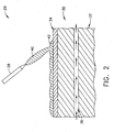
- FIG. 2 is a schematic representation of a high temperature additive manufacturing system comprising tooling system 30 suitable for use in conjunction with high temperature additive manufacturing of titanium and titanium alloys.
- tooling system 30 includes a mandrel 32, a metallic cladding 34, and at least one cooling channel 36 for use with a high temperature additive manufacturing device 38.
- Mandrel 32 can receive a metallic deposit 40 and can have a shape corresponding to the desired shape of MLE protective strip 28.
- Mandrel 32 can be single-use or reusable, and can be made from any metallic or nonmetallic material.
- mandrel 32 should have a thermal conductivity that is at least about two times the thermal conductivity of the metallic deposit. This difference in thermal conductivity can also allow mandrel 32 to serve as a heat sink, thereby providing a larger process window for making a sound deposit without fusion to the mandrel when compared to current practices.
- suitable "metallic materials” for mandrel 32 include, but should not be limited to, titanium, titanium alloy, molybdenum, tungsten, mild steel, and copper, while some examples of suitable nonmetallic materials include, but should not be limited to, graphite, silicon carbide, and carbon-carbon composite.
- Metallic cladding (or “cladding”) 34 comprises a thin layer of the titanium or titanium alloy in metallic deposit 40 applied to mandrel 32. Cladding 34 serves to further prevent contamination of metallic deposit 40. Cladding 34 can be applied to mandrel 32 by a variety of methods, including plasma spray, roll bonding, plasma transferred arc deposition, arc weld overlay (shielded metal arc welding (SMAW), gas metal arc welding (GMAW), gas tungsten arc welding (GTAW)), flame spray, and physical vapor deposition (PVD).
- the thickness of cladding 34 can range from about 2 microns to about 2mm, and in one embodiment, from about 2 microns to about 1mm. Conventional heat transfer modeling can be used to determine the optimized coating thickness for the particular cladding material being used.
- active cooling of mandrel 32 is desired to remove heat and further help prevent fusion of MLE protective strip 28 to mandrel 32 and cladding 34. Active cooling can also be used help control grain size of the deposit material and optimize the mechanical and corrosion performance of MLE protection strip 28. Active cooling is according to the present invention, accomplished through the use of at least one cooling channel 36 in association with mandrel 32. Such cooling channels 36 can be attached to mandrel 32, embedded into mandrel 32 (as shown in FIG. 2 ), machined into mandrel 32, or some combination thereof. An active cooling medium can then be passed through cooling channel 36 (as indicated by arrows) to remove heat from mandrel 32.
- the active cooling medium can be a liquid, such as water or glycol, or a gas, such as argon, nitrogen, air, or helium.
- high temperature additive manufacturing device 38 can be positioned above tooling system 30 for providing metallic deposit 40.
- the application of metallic (titanium or titanium alloy) deposit 40 to mandrel 32 can be accomplished using conventional techniques as described previously.
- the resulting near net shape MLE protective strip 28 can be processed further.
- MLE protective strip 28 may be finished to final dimensions using conventional methods (e.g. machining) before being removed from mandrel 32 and attached to airfoil leading edge 16. In another embodiment, any required finishing operations can be carried out after protective strip 28 is attached to airfoil leading edge 16.
- MLE protective strip 28 can then be operably connected to airfoil leading edge 16 using a variety of conventional methods.
- the embodiments herein offer benefits over conventional MLE protective strip manufacturing technologies. More particularly, additive manufacturing allows for the leading edge protective strip to be built up to near net shape, thereby reducing material input, material waste, and overall manufacturing time. Applying only the amount of material needed to complete the component conserves expensive raw materials, and material removal and finishing needs (e.g. machining) are drastically reduced. Moreover, additive manufacturing allows for flexibility in changing or updating the design of the MLE protective strip quickly and at a low cost when compared to conventional machining methods. Furthermore, utilizing additive manufacturing processes allows the MLE protective strip to be functionally graded in composition to tailor the properties and structure, thereby allowing advanced design capability.
Landscapes
- Engineering & Computer Science (AREA)
- Mechanical Engineering (AREA)
- Physics & Mathematics (AREA)
- Optics & Photonics (AREA)
- Plasma & Fusion (AREA)
- Chemical & Material Sciences (AREA)
- Manufacturing & Machinery (AREA)
- Materials Engineering (AREA)
- General Engineering & Computer Science (AREA)
- Chemical Kinetics & Catalysis (AREA)
- Organic Chemistry (AREA)
- Metallurgy (AREA)
- Structures Of Non-Positive Displacement Pumps (AREA)
- Turbine Rotor Nozzle Sealing (AREA)
- Other Surface Treatments For Metallic Materials (AREA)
- Welding Or Cutting Using Electron Beams (AREA)
- Coating By Spraying Or Casting (AREA)
- Pressure Welding/Diffusion-Bonding (AREA)
Description
- Embodiments described herein generally relate to a high temperature additive manufacturing system according to the preamble of claim 1, for making near net shape airfoil leading edge protection and tooling systems for use therewith.
- Many modem turbine engine airfoils, such as blades and vanes, are constructed of a composite laminate or molded fiber. Airfoil metal leading edge (herein "MLE") protective strips can be used to protect composite airfoils from impact and erosion damage that can often occur in the engine environment. In conventional practices, a v-shaped protective metallic strip is often wrapped around the leading edge and sides of the airfoil to provide such protection.
- While MLE protective strips can be made from a variety of materials, titanium and titanium alloys are often utilized due to their favorable weight and mechanical properties. However, hot forming methods must be used to fabricate these titanium components. Hot forming typically involves multiple steps with intermediate chemical milling or machining. This can lead to high tooling costs, high yield losses, and environmentally unfriendly processing. These drawbacks are especially true when fabricating thin, complex geometries, such as MLE protective strips.
- Additive manufacturing involves the buildup of a metal part or preform to make a net, or near net shape (NNS) component. This approach can make complex components from expensive materials for a reduced cost and with improved manufacturing efficiency. Generally, a freestanding component is built from a computer aided design (CAD) model. However, when the component has a thin and/or complex shape, it can be beneficial to build up the component on a tool for support.
- When a high temperature, melt-based process, such as plasma transferred arc or laser cladding, is used as the additive method to make a NNS component, the tool must perform several functions: it must give shape to the part, it must control heat input to provide a uniform microstructure over the entire length of the component with the desired grain size, and it must conduct heat away from the deposit rapidly enough to prevent fusion of the deposited component to the tool. Additionally, the tool must not cause any contamination of the metallic deposit, as contamination can have a disastrous affect on the physical and mechanical properties of the component. This is especially true when working with titanium and titanium alloys.
- More specifically, when titanium or titanium alloy is deposited, the risk of contamination of the deposit by the tooling is high due to the high melting point and reactive nature of titanium. Current practice utilizes a monolithic tool made from the same alloy that is being deposited (e.g. titanium or titanium alloy). While this approach helps mitigate the issue of contamination, it results in a very narrow process window for making a sound deposit without fusion of the deposit to the tool. This is because titanium is a relatively poor heat conductor when compared to other heat sink materials (e.g. refractory metals, mild steel, copper).
- Accordingly, there remains a need for manufacturing and tooling systems that address and overcome the previously discussed issues associated with current MLE protective strip manufacturing.
-
GB 2,245,514 US 4,782,206 discloses a method and apparatus for eliminating microfissure defects in shape melted austenitic components through close monitoring of a deposited weld bead shape. - The present invention provides a high temperature additive manufacturing system according to claim 1.
- Embodiments herein also generally relate to high temperature additive manufacturing systems comprising a high temperature additive manufacturing device for providing a metallic deposit; and a tooling system comprising: a mandrel for receiving, and providing shape to, the metallic deposit; a metallic cladding applied to the mandrel for reducing contamination of the metallic deposit; and at least one cooling channel associated with the mandrel for removing heat from the system.
- These and other features, aspects and advantages will become evident to those skilled in the art from the following disclosure.
- There follows a detailed description of embodiments of the invention by way of example only with reference to the accompanying drawings, in which:
-
FIG. 1 is a schematic representation of one embodiment of a composite fan blade for a gas turbine engine in accordance with the description herein; and -
FIG. 2 is a schematic cross-sectional representation of a portion of one embodiment of a high temperature additive manufacturing system in accordance with the description herein. - Embodiments described herein generally relate to high temperature additive manufacturing systems for making near net shape airfoil leading edge protective strips and tooling systems for use therewith.
-
FIG. 1 is acomposite fan blade 10 for a gas turbine engine having acomposite airfoil 12 generally extending in a chordwise direction C from a leadingedge 16 to atrailing edge 18. Airfoil 12 extends radially outward in a spanwise direction S from aroot 20 to atip 22 generally defining its span and having asuction side 24 and apressure side 26.Airfoil 12 can be constructed from plies of composite material as is known in the art. Embodiments herein describe methods and tooling for making a titanium or titanium alloy metal leading edge (MLE)protective strip 28 for adhesion toairfoil leading edge 16. Though embodiments herein focus on composite fan blades, the methods, tooling and MLE protective strips herein are suitable for use with any composite airfoil, including blades and vanes. - MLE
protective strip 28 can be made using high temperature additive manufacturing processes. As used herein, "high temperature additive manufacturing" refers to processes including plasma transferred arc deposition, laser cladding, gas metal arc welding, ultrasonic welding, electron beam free-from fabrication, shaped metal deposition, and the like. Such processes have operating temperatures in excess of about 3000°C, which in the present case, is well above the melting point of the titanium or titanium alloy metallic deposit. To overcome the previously described issues common to such processes when working with high melting point and/or reactive materials, unique tooling must be employed.FIG. 2 is a schematic representation of a high temperature additive manufacturing system comprising tooling system 30 suitable for use in conjunction with high temperature additive manufacturing of titanium and titanium alloys. - More particularly, tooling system 30 includes a
mandrel 32, ametallic cladding 34, and at least onecooling channel 36 for use with a high temperatureadditive manufacturing device 38. Mandrel 32 can receive ametallic deposit 40 and can have a shape corresponding to the desired shape of MLEprotective strip 28. Mandrel 32 can be single-use or reusable, and can be made from any metallic or nonmetallic material. To help prevent contamination ofmetallic deposit 40,mandrel 32 should have a thermal conductivity that is at least about two times the thermal conductivity of the metallic deposit. This difference in thermal conductivity can also allowmandrel 32 to serve as a heat sink, thereby providing a larger process window for making a sound deposit without fusion to the mandrel when compared to current practices. Some examples of suitable "metallic materials" formandrel 32 include, but should not be limited to, titanium, titanium alloy, molybdenum, tungsten, mild steel, and copper, while some examples of suitable nonmetallic materials include, but should not be limited to, graphite, silicon carbide, and carbon-carbon composite. - Metallic cladding (or "cladding") 34 comprises a thin layer of the titanium or titanium alloy in
metallic deposit 40 applied tomandrel 32. Cladding 34 serves to further prevent contamination ofmetallic deposit 40. Cladding 34 can be applied tomandrel 32 by a variety of methods, including plasma spray, roll bonding, plasma transferred arc deposition, arc weld overlay (shielded metal arc welding (SMAW), gas metal arc welding (GMAW), gas tungsten arc welding (GTAW)), flame spray, and physical vapor deposition (PVD). The thickness ofcladding 34 can range from about 2 microns to about 2mm, and in one embodiment, from about 2 microns to about 1mm. Conventional heat transfer modeling can be used to determine the optimized coating thickness for the particular cladding material being used. - In addition to cladding 34, active cooling of
mandrel 32 is desired to remove heat and further help prevent fusion of MLEprotective strip 28 tomandrel 32 and cladding 34. Active cooling can also be used help control grain size of the deposit material and optimize the mechanical and corrosion performance ofMLE protection strip 28. Active cooling is according to the present invention, accomplished through the use of at least onecooling channel 36 in association withmandrel 32.Such cooling channels 36 can be attached tomandrel 32, embedded into mandrel 32 (as shown inFIG. 2 ), machined intomandrel 32, or some combination thereof. An active cooling medium can then be passed through cooling channel 36 (as indicated by arrows) to remove heat frommandrel 32. The active cooling medium can be a liquid, such as water or glycol, or a gas, such as argon, nitrogen, air, or helium. - In use, high temperature
additive manufacturing device 38 can be positioned above tooling system 30 for providingmetallic deposit 40. The application of metallic (titanium or titanium alloy)deposit 40 tomandrel 32 can be accomplished using conventional techniques as described previously. Once cooled to about ambient temperatures, the resulting near net shape MLEprotective strip 28 can be processed further. In one embodiment, MLEprotective strip 28 may be finished to final dimensions using conventional methods (e.g. machining) before being removed frommandrel 32 and attached toairfoil leading edge 16. In another embodiment, any required finishing operations can be carried out afterprotective strip 28 is attached toairfoil leading edge 16. MLEprotective strip 28 can then be operably connected toairfoil leading edge 16 using a variety of conventional methods. - The embodiments herein offer benefits over conventional MLE protective strip manufacturing technologies. More particularly, additive manufacturing allows for the leading edge protective strip to be built up to near net shape, thereby reducing material input, material waste, and overall manufacturing time. Applying only the amount of material needed to complete the component conserves expensive raw materials, and material removal and finishing needs (e.g. machining) are drastically reduced. Moreover, additive manufacturing allows for flexibility in changing or updating the design of the MLE protective strip quickly and at a low cost when compared to conventional machining methods. Furthermore, utilizing additive manufacturing processes allows the MLE protective strip to be functionally graded in composition to tailor the properties and structure, thereby allowing advanced design capability.
- This written description uses examples to disclose the invention, including the best mode, and also to enable any person skilled in the art to make and use the invention. The patentable scope of the invention is defmed by the claims, and may include other examples that occur to those skilled in the art. Such other examples are intended to be within the scope of the claims.
Claims (8)
- A high temperature additive manufacturing system (29) for making a component comprising titanium or a titanium alloy, wherein the system (29) comprises:a metallic deposit (40) comprising titanium or a titanium alloy;a high temperature additive manufacturing device (38) for application of the metallic deposit (40); anda tooling system (30) comprising:a mandrel (32) for receiving the metallic deposit (40) from the high temperature additive manufacturing device (29), and providing shape to the metallic deposit (40);characterised in that the system (29) further comprises:at least one cooling channel (36) associated with the mandrel (32) for removing heat from the system (30); anda metallic cladding (34) is applied to the mandrel (32) and comprising the same material as the metallic deposit (40), for thereby reducing contamination of the metallic deposit (40).
- An additive manufacturing system (29) according to claim 1, wherein the mandrel (32) comprises a thermal conductivity at least two times greater than the thermal conductivity of the metallic deposit (40).
- An additive manufacturing system (29) according to either of claim 1 or 2, wherein the mandrel (32) comprises a metallic material selected from the group consisting of titanium, titanium alloy, molybdenum, tungsten, mild steel, and copper, or a nonmetallic material selected from the group consisting of graphite, silicon carbide, and carbon-carbon composite.
- An additive manufacturing system (29) according to any of claims 1 to 3, wherein the high temperature additive manufacturing device (38) is capable of carrying out a process selected from the group consisting of plasma transferred arc deposition, laser cladding, gas metal arc welding, ultrasonic welding, electron beam free-form fabrication, and shaped metal deposition.
- An additive manufacturing system (29) according to any of claims 1 to 4, wherein the high temperature additive manufacturing device (38) comprises an operating temperature above 3000°C.
- An additive manufacturing system (29) according to any of claims 1 to 5, wherein the metallic cladding (34) is applied to the mandrel (32) using a process selected from the group consisting of plasma spray, roll bonding, plasma transferred arc deposition, arc weld overlay, flame spray, and physical vapor deposition.
- An additive manufacturing system (29) according to any of claims 1 to 6, wherein the cladding (34) comprises a thickness of from 2 microns to 2mm.
- An additive manufacturing system (29) according to any of claims 1 to 7, comprising more than one cooling channel (36).
Applications Claiming Priority (1)
| Application Number | Priority Date | Filing Date | Title |
|---|---|---|---|
| US12/409,904 US20100242843A1 (en) | 2009-03-24 | 2009-03-24 | High temperature additive manufacturing systems for making near net shape airfoils leading edge protection, and tooling systems therewith |
Publications (2)
| Publication Number | Publication Date |
|---|---|
| EP2236235A1 EP2236235A1 (en) | 2010-10-06 |
| EP2236235B1 true EP2236235B1 (en) | 2015-05-20 |
Family
ID=42288964
Family Applications (1)
| Application Number | Title | Priority Date | Filing Date |
|---|---|---|---|
| EP20100157403 Active EP2236235B1 (en) | 2009-03-24 | 2010-03-23 | A high temperature additive manufacturing system for making near net shape airfoil leading edge protection with a cladded mandrel |
Country Status (4)
| Country | Link |
|---|---|
| US (1) | US20100242843A1 (en) |
| EP (1) | EP2236235B1 (en) |
| JP (1) | JP5926476B2 (en) |
| CA (1) | CA2697571C (en) |
Families Citing this family (53)
| Publication number | Priority date | Publication date | Assignee | Title |
|---|---|---|---|---|
| US8240046B2 (en) * | 2009-03-24 | 2012-08-14 | General Electric Company | Methods for making near net shape airfoil leading edge protection |
| US20110097213A1 (en) * | 2009-03-24 | 2011-04-28 | Peretti Michael W | Composite airfoils having leading edge protection made using high temperature additive manufacturing methods |
| WO2012061573A1 (en) * | 2010-11-05 | 2012-05-10 | Barnes Group Inc. | Hybrid metal leding edge part and method for making the same |
| GB2493537A (en) * | 2011-08-10 | 2013-02-13 | Bae Systems Plc | Forming a layered structure |
| GB2493538A (en) * | 2011-08-10 | 2013-02-13 | Bae Systems Plc | Forming a structure by added layer manufacture |
| US11000899B2 (en) | 2012-01-29 | 2021-05-11 | Raytheon Technologies Corporation | Hollow airfoil construction utilizing functionally graded materials |
| CN108500184A (en) | 2013-07-10 | 2018-09-07 | 奥科宁克有限公司 | Method for making forging product and other converted products |
| US9695697B2 (en) * | 2013-09-25 | 2017-07-04 | General Electric Company | Erosion shield, method of fabricating a shield, and method of fabricating an article having a shield |
| US10174621B2 (en) | 2013-10-07 | 2019-01-08 | United Technologies Corporation | Method of making an article with internal structure |
| CN104014912B (en) * | 2014-06-07 | 2016-02-17 | 中国人民解放军装甲兵工程学院 | The arc-welding of a kind of titanium or titanium alloy component increases material reproducing method |
| GB2546016B (en) | 2014-06-20 | 2018-11-28 | Velo3D Inc | Apparatuses, systems and methods for three-dimensional printing |
| FR3026033B1 (en) * | 2014-09-19 | 2017-03-24 | Snecma | METHOD FOR MANUFACTURING ATTACK EDGE SHIELD |
| CN107429570B (en) * | 2015-04-17 | 2020-06-09 | 三菱日立电力系统株式会社 | Steam turbine rotor blade and method for manufacturing steam turbine rotor blade |
| CN104942407B (en) * | 2015-06-16 | 2016-11-30 | 哈尔滨工业大学 | A kind of Tig Welding method of network structure titanium matrix composite |
| BE1023290B1 (en) * | 2015-07-22 | 2017-01-24 | Safran Aero Boosters S.A. | AUBE COMPOSITE COMPRESSOR OF AXIAL TURBOMACHINE |
| EP3352970A1 (en) * | 2015-09-25 | 2018-08-01 | Addifab ApS | Additive manufacturing device and system, modular build platform and build platform unit |
| JP2018535121A (en) | 2015-11-06 | 2018-11-29 | ヴェロ・スリー・ディー・インコーポレイテッド | Proficient 3D printing |
| US20170145586A1 (en) * | 2015-11-23 | 2017-05-25 | Hobart Brothers Company | System and method for single crystal growth with additive manufacturing |
| US10207454B2 (en) | 2015-12-10 | 2019-02-19 | Velo3D, Inc. | Systems for three-dimensional printing |
| CN108472712A (en) * | 2016-01-14 | 2018-08-31 | 奥科宁克公司 | Method for producing forging product and other converted products |
| US20170239891A1 (en) | 2016-02-18 | 2017-08-24 | Velo3D, Inc. | Accurate three-dimensional printing |
| US10677259B2 (en) | 2016-05-06 | 2020-06-09 | General Electric Company | Apparatus and system for composite fan blade with fused metal lead edge |
| US11691343B2 (en) | 2016-06-29 | 2023-07-04 | Velo3D, Inc. | Three-dimensional printing and three-dimensional printers |
| WO2018005439A1 (en) | 2016-06-29 | 2018-01-04 | Velo3D, Inc. | Three-dimensional printing and three-dimensional printers |
| US20180095450A1 (en) | 2016-09-30 | 2018-04-05 | Velo3D, Inc. | Three-dimensional objects and their formation |
| US10661341B2 (en) | 2016-11-07 | 2020-05-26 | Velo3D, Inc. | Gas flow in three-dimensional printing |
| US20180186080A1 (en) | 2017-01-05 | 2018-07-05 | Velo3D, Inc. | Optics in three-dimensional printing |
| WO2018160807A1 (en) | 2017-03-02 | 2018-09-07 | Velo3D, Inc. | Three-dimensional printing of three dimensional objects |
| US10449696B2 (en) | 2017-03-28 | 2019-10-22 | Velo3D, Inc. | Material manipulation in three-dimensional printing |
| US10471542B1 (en) * | 2017-06-27 | 2019-11-12 | United States Of America As Represented By The Administrator Of Nasa | Cladding and freeform deposition for coolant channel closeout |
| SG11202002484XA (en) * | 2017-10-10 | 2020-04-29 | Applied Materials Inc | Selective powder delivery for additive manufacturing |
| US10272525B1 (en) | 2017-12-27 | 2019-04-30 | Velo3D, Inc. | Three-dimensional printing systems and methods of their use |
| US10144176B1 (en) | 2018-01-15 | 2018-12-04 | Velo3D, Inc. | Three-dimensional printing systems and methods of their use |
| CN110605456A (en) * | 2018-06-15 | 2019-12-24 | 天津大学 | A kind of titanium alloy CMT-heat treatment composite additive manufacturing method |
| US11426818B2 (en) | 2018-08-10 | 2022-08-30 | The Research Foundation for the State University | Additive manufacturing processes and additively manufactured products |
| US11149558B2 (en) | 2018-10-16 | 2021-10-19 | General Electric Company | Frangible gas turbine engine airfoil with layup change |
| US11434781B2 (en) | 2018-10-16 | 2022-09-06 | General Electric Company | Frangible gas turbine engine airfoil including an internal cavity |
| US10746045B2 (en) | 2018-10-16 | 2020-08-18 | General Electric Company | Frangible gas turbine engine airfoil including a retaining member |
| US11111815B2 (en) | 2018-10-16 | 2021-09-07 | General Electric Company | Frangible gas turbine engine airfoil with fusion cavities |
| US10760428B2 (en) | 2018-10-16 | 2020-09-01 | General Electric Company | Frangible gas turbine engine airfoil |
| US10837286B2 (en) | 2018-10-16 | 2020-11-17 | General Electric Company | Frangible gas turbine engine airfoil with chord reduction |
| CA3148849A1 (en) | 2019-07-26 | 2021-02-04 | Velo3D, Inc. | Quality assurance in formation of three-dimensional objects |
| US12415229B2 (en) | 2020-07-29 | 2025-09-16 | Blue Origin Manufacturing, LLC | Friction stir welding systems and methods |
| US12116903B2 (en) | 2021-06-30 | 2024-10-15 | General Electric Company | Composite airfoils with frangible tips |
| US11674399B2 (en) | 2021-07-07 | 2023-06-13 | General Electric Company | Airfoil arrangement for a gas turbine engine utilizing a shape memory alloy |
| US11668317B2 (en) | 2021-07-09 | 2023-06-06 | General Electric Company | Airfoil arrangement for a gas turbine engine utilizing a shape memory alloy |
| KR20240035613A (en) * | 2021-08-25 | 2024-03-15 | 하이퍼썸, 인크. | Edge forming using material handling systems |
| US12246392B2 (en) | 2023-03-30 | 2025-03-11 | Blue Origin Manufacturing, LLC | Deposition head for friction stir additive manufacturing devices and methods |
| US12172229B2 (en) | 2023-03-30 | 2024-12-24 | Blue Origin, Llc | Friction stir additive manufacturing devices and methods for forming in-situ rivets |
| US12140109B2 (en) | 2023-03-30 | 2024-11-12 | Blue Origin, Llc | Transpiration-cooled systems having permeable and non-permeable portions |
| US12383975B2 (en) | 2023-08-03 | 2025-08-12 | Blue Origin Manufacturing, LLC | Friction stir additive manufacturing formed parts and structures with integrated passages |
| US12303994B2 (en) | 2023-08-03 | 2025-05-20 | Blue Origin Manufacturing, LLC | Friction stir additive manufacturing formed parts and structures with integrated passages |
| US20250187106A1 (en) | 2023-12-12 | 2025-06-12 | Blue Origin, Llc | Nosecones for friction stir additive manufacturing systems, devices, and methods |
Citations (23)
| Publication number | Priority date | Publication date | Assignee | Title |
|---|---|---|---|---|
| US4006999A (en) | 1975-07-17 | 1977-02-08 | The United States Of America As Represented By The Administrator Of The National Aeronautics And Space Administration | Leading edge protection for composite blades |
| US4237361A (en) | 1975-04-30 | 1980-12-02 | August Thyssen Aktiengesellschaft | Buildup welding of inclined surfaces |
| GB1599392A (en) | 1978-05-31 | 1981-09-30 | Osprey Metals Ltd | Method and apparatus for producing workable spray deposits |
| US4537742A (en) | 1983-10-28 | 1985-08-27 | General Electric Company | Method for controlling dimensions of RSPD articles |
| EP0188994A1 (en) | 1984-12-21 | 1986-07-30 | MANNESMANN Aktiengesellschaft | Process and device for producing a metallic block |
| US4782206A (en) | 1987-01-27 | 1988-11-01 | The Babcock & Wilcox Company | Method and apparatus for controlling weld bead shape to eliminate microfissure defects when shape melting austenitic materials |
| EP0358800A1 (en) | 1987-02-04 | 1990-03-21 | General Electric Company | Method for finishing the surface of plasma sprayed titanium-based alloy foils |
| US5012853A (en) | 1988-09-20 | 1991-05-07 | Sundstrand Corporation | Process for making articles with smooth complex internal geometries |
| US5074923A (en) | 1990-03-26 | 1991-12-24 | General Electric Company | Method for id sizing of filament reinforced annular objects |
| FR2663872A1 (en) | 1990-06-29 | 1992-01-03 | Gen Electric | MANUFACTURE OF TUBES USING A REUSABLE CHUCK. |
| US5165859A (en) | 1992-06-26 | 1992-11-24 | Hudson Products Corporation | Leading edge protection for fan blade |
| US5210946A (en) | 1992-06-26 | 1993-05-18 | Hudson Products Corporation | Leading edge protection for fan blade |
| US5449273A (en) | 1994-03-21 | 1995-09-12 | United Technologies Corporation | Composite airfoil leading edge protection |
| US5453329A (en) | 1992-06-08 | 1995-09-26 | Quantum Laser Corporation | Method for laser cladding thermally insulated abrasive particles to a substrate, and clad substrate formed thereby |
| US5785498A (en) | 1994-09-30 | 1998-07-28 | General Electric Company | Composite fan blade trailing edge reinforcement |
| JPH11256306A (en) | 1997-12-29 | 1999-09-21 | Ford Global Technol Inc | Spray forming method of insert |
| WO2000020146A1 (en) | 1998-10-08 | 2000-04-13 | Promet Technologies, Inc. | Nickel-titanium seamless tubes |
| US6063212A (en) | 1998-05-12 | 2000-05-16 | United Technologies Corporation | Heat treated, spray formed superalloy articles and method of making the same |
| US6168871B1 (en) | 1998-03-06 | 2001-01-02 | General Electric Company | Method of forming high-temperature components and components formed thereby |
| JP2005194599A (en) | 2004-01-09 | 2005-07-21 | Mitsubishi Heavy Ind Ltd | Plasma spraying apparatus and method for detecting temperature of spray particle in the apparatus |
| US20060248718A1 (en) | 2005-05-06 | 2006-11-09 | United Technologies Corporation | Superalloy repair methods and inserts |
| US20070243071A1 (en) | 1995-03-06 | 2007-10-18 | Mannava Seetha R | Laser shock peened gas turbine engine compressor airfoil edges |
| US20090025365A1 (en) | 2007-07-23 | 2009-01-29 | General Electric Company | Airfoil and method for protecting airfoil leading edge |
-
2009
- 2009-03-24 US US12/409,904 patent/US20100242843A1/en not_active Abandoned
-
2010
- 2010-03-23 CA CA2697571A patent/CA2697571C/en not_active Expired - Fee Related
- 2010-03-23 EP EP20100157403 patent/EP2236235B1/en active Active
- 2010-03-23 JP JP2010065577A patent/JP5926476B2/en not_active Expired - Fee Related
Patent Citations (27)
| Publication number | Priority date | Publication date | Assignee | Title |
|---|---|---|---|---|
| US4237361A (en) | 1975-04-30 | 1980-12-02 | August Thyssen Aktiengesellschaft | Buildup welding of inclined surfaces |
| US4006999A (en) | 1975-07-17 | 1977-02-08 | The United States Of America As Represented By The Administrator Of The National Aeronautics And Space Administration | Leading edge protection for composite blades |
| GB1599392A (en) | 1978-05-31 | 1981-09-30 | Osprey Metals Ltd | Method and apparatus for producing workable spray deposits |
| US4537742A (en) | 1983-10-28 | 1985-08-27 | General Electric Company | Method for controlling dimensions of RSPD articles |
| EP0188994A1 (en) | 1984-12-21 | 1986-07-30 | MANNESMANN Aktiengesellschaft | Process and device for producing a metallic block |
| US4782206A (en) | 1987-01-27 | 1988-11-01 | The Babcock & Wilcox Company | Method and apparatus for controlling weld bead shape to eliminate microfissure defects when shape melting austenitic materials |
| EP0358800A1 (en) | 1987-02-04 | 1990-03-21 | General Electric Company | Method for finishing the surface of plasma sprayed titanium-based alloy foils |
| US5012853A (en) | 1988-09-20 | 1991-05-07 | Sundstrand Corporation | Process for making articles with smooth complex internal geometries |
| US5074923A (en) | 1990-03-26 | 1991-12-24 | General Electric Company | Method for id sizing of filament reinforced annular objects |
| FR2663872A1 (en) | 1990-06-29 | 1992-01-03 | Gen Electric | MANUFACTURE OF TUBES USING A REUSABLE CHUCK. |
| GB2245514A (en) * | 1990-06-29 | 1992-01-08 | Gen Electric | Tube fabrication with reusable mandrel |
| US5453329A (en) | 1992-06-08 | 1995-09-26 | Quantum Laser Corporation | Method for laser cladding thermally insulated abrasive particles to a substrate, and clad substrate formed thereby |
| US5210946A (en) | 1992-06-26 | 1993-05-18 | Hudson Products Corporation | Leading edge protection for fan blade |
| US5165859A (en) | 1992-06-26 | 1992-11-24 | Hudson Products Corporation | Leading edge protection for fan blade |
| US5449273A (en) | 1994-03-21 | 1995-09-12 | United Technologies Corporation | Composite airfoil leading edge protection |
| US5785498A (en) | 1994-09-30 | 1998-07-28 | General Electric Company | Composite fan blade trailing edge reinforcement |
| US20070243071A1 (en) | 1995-03-06 | 2007-10-18 | Mannava Seetha R | Laser shock peened gas turbine engine compressor airfoil edges |
| JPH11256306A (en) | 1997-12-29 | 1999-09-21 | Ford Global Technol Inc | Spray forming method of insert |
| EP0927816B1 (en) | 1997-12-29 | 2003-08-13 | Ford Global Technologies, Inc. | Method of making spray-formed inserts |
| US6168871B1 (en) | 1998-03-06 | 2001-01-02 | General Electric Company | Method of forming high-temperature components and components formed thereby |
| US6063212A (en) | 1998-05-12 | 2000-05-16 | United Technologies Corporation | Heat treated, spray formed superalloy articles and method of making the same |
| WO2000020146A1 (en) | 1998-10-08 | 2000-04-13 | Promet Technologies, Inc. | Nickel-titanium seamless tubes |
| JP2005194599A (en) | 2004-01-09 | 2005-07-21 | Mitsubishi Heavy Ind Ltd | Plasma spraying apparatus and method for detecting temperature of spray particle in the apparatus |
| US20060248718A1 (en) | 2005-05-06 | 2006-11-09 | United Technologies Corporation | Superalloy repair methods and inserts |
| US20090025365A1 (en) | 2007-07-23 | 2009-01-29 | General Electric Company | Airfoil and method for protecting airfoil leading edge |
| EP2022942A1 (en) | 2007-07-23 | 2009-02-11 | General Electric Company | Airfoil and method for protecting airfoil leading edge |
| US20090053067A1 (en) | 2007-07-23 | 2009-02-26 | General Electric Company | Airfoil and method for protecting airfoil leading edge |
Also Published As
| Publication number | Publication date |
|---|---|
| EP2236235A1 (en) | 2010-10-06 |
| JP2010222705A (en) | 2010-10-07 |
| CA2697571C (en) | 2017-07-25 |
| US20100242843A1 (en) | 2010-09-30 |
| CA2697571A1 (en) | 2010-09-24 |
| JP5926476B2 (en) | 2016-05-25 |
Similar Documents
| Publication | Publication Date | Title |
|---|---|---|
| CA2697571C (en) | High temperature additive manufacturing systems for making near net shape airfoil leading edge protection, and tooling systems therewith | |
| US8240046B2 (en) | Methods for making near net shape airfoil leading edge protection | |
| US20110097213A1 (en) | Composite airfoils having leading edge protection made using high temperature additive manufacturing methods | |
| US5822852A (en) | Method for replacing blade tips of directionally solidified and single crystal turbine blades | |
| JP5757720B2 (en) | Abrasive single crystal turbine blade | |
| US20240082914A1 (en) | Method for repairing an ultra-thin structure by additive manufacturing | |
| EP1688211B1 (en) | Plasma arc weld repair of high nickel metal alloys | |
| US11655717B2 (en) | Turbine blade squealer tip including internal squealer tip cooling channel | |
| CA2823525C (en) | Method for producing a metal reinforcement | |
| JP7038545B2 (en) | Repairing brazed structure of difficult-to-weld superalloy parts using diffusion alloy inserts | |
| EP2684981B1 (en) | A coating/repairing process using electrospark with PSP rod | |
| EP2327812A1 (en) | Near net shape composite airfoil leading edge protective strips made using cold spray deposition | |
| CN104420896B (en) | Reforming technology and the product of transformation | |
| EP3332902B1 (en) | Systems and methods for making blade metal sheaths | |
| US20220324046A1 (en) | Method for Manufacturing Core Plug of Gas Turbine Vane Using Brazing | |
| JP6475701B2 (en) | Hollow metal part and manufacturing method thereof | |
| JP2018168851A5 (en) | ||
| WO2019014445A1 (en) | Method of repairing an article and associated article | |
| CN104451674A (en) | Erosion shield, method of fabricating a shield, and method of fabricating an article having a shield | |
| CN102811835A (en) | Method for reprocessing a turbine blade having at least one platform | |
| US7896221B2 (en) | Method of manufacturing an aerofoil | |
| Pathak et al. | Cold spray: its prominence as an additive manufacturing technology | |
| EP2236770B1 (en) | Gas turbine engine article having columnar microstructure | |
| EP2036650B1 (en) | Joining method | |
| EP4397788A1 (en) | Wear resistant article and method of making |
Legal Events
| Date | Code | Title | Description |
|---|---|---|---|
| PUAI | Public reference made under article 153(3) epc to a published international application that has entered the european phase |
Free format text: ORIGINAL CODE: 0009012 |
|
| AK | Designated contracting states |
Kind code of ref document: A1 Designated state(s): AT BE BG CH CY CZ DE DK EE ES FI FR GB GR HR HU IE IS IT LI LT LU LV MC MK MT NL NO PL PT RO SE SI SK SM TR |
|
| AX | Request for extension of the european patent |
Extension state: AL BA ME RS |
|
| 17P | Request for examination filed |
Effective date: 20110406 |
|
| 17Q | First examination report despatched |
Effective date: 20110906 |
|
| GRAP | Despatch of communication of intention to grant a patent |
Free format text: ORIGINAL CODE: EPIDOSNIGR1 |
|
| INTG | Intention to grant announced |
Effective date: 20150112 |
|
| GRAS | Grant fee paid |
Free format text: ORIGINAL CODE: EPIDOSNIGR3 |
|
| GRAA | (expected) grant |
Free format text: ORIGINAL CODE: 0009210 |
|
| AK | Designated contracting states |
Kind code of ref document: B1 Designated state(s): AT BE BG CH CY CZ DE DK EE ES FI FR GB GR HR HU IE IS IT LI LT LU LV MC MK MT NL NO PL PT RO SE SI SK SM TR |
|
| REG | Reference to a national code |
Ref country code: GB Ref legal event code: FG4D |
|
| REG | Reference to a national code |
Ref country code: CH Ref legal event code: EP |
|
| REG | Reference to a national code |
Ref country code: AT Ref legal event code: REF Ref document number: 727476 Country of ref document: AT Kind code of ref document: T Effective date: 20150615 |
|
| REG | Reference to a national code |
Ref country code: IE Ref legal event code: FG4D |
|
| REG | Reference to a national code |
Ref country code: DE Ref legal event code: R096 Ref document number: 602010024707 Country of ref document: DE |
|
| REG | Reference to a national code |
Ref country code: AT Ref legal event code: MK05 Ref document number: 727476 Country of ref document: AT Kind code of ref document: T Effective date: 20150520 |
|
| REG | Reference to a national code |
Ref country code: LT Ref legal event code: MG4D |
|
| REG | Reference to a national code |
Ref country code: NL Ref legal event code: MP Effective date: 20150520 |
|
| PG25 | Lapsed in a contracting state [announced via postgrant information from national office to epo] |
Ref country code: ES Free format text: LAPSE BECAUSE OF FAILURE TO SUBMIT A TRANSLATION OF THE DESCRIPTION OR TO PAY THE FEE WITHIN THE PRESCRIBED TIME-LIMIT Effective date: 20150520 Ref country code: HR Free format text: LAPSE BECAUSE OF FAILURE TO SUBMIT A TRANSLATION OF THE DESCRIPTION OR TO PAY THE FEE WITHIN THE PRESCRIBED TIME-LIMIT Effective date: 20150520 Ref country code: FI Free format text: LAPSE BECAUSE OF FAILURE TO SUBMIT A TRANSLATION OF THE DESCRIPTION OR TO PAY THE FEE WITHIN THE PRESCRIBED TIME-LIMIT Effective date: 20150520 Ref country code: NO Free format text: LAPSE BECAUSE OF FAILURE TO SUBMIT A TRANSLATION OF THE DESCRIPTION OR TO PAY THE FEE WITHIN THE PRESCRIBED TIME-LIMIT Effective date: 20150820 Ref country code: LT Free format text: LAPSE BECAUSE OF FAILURE TO SUBMIT A TRANSLATION OF THE DESCRIPTION OR TO PAY THE FEE WITHIN THE PRESCRIBED TIME-LIMIT Effective date: 20150520 Ref country code: PT Free format text: LAPSE BECAUSE OF FAILURE TO SUBMIT A TRANSLATION OF THE DESCRIPTION OR TO PAY THE FEE WITHIN THE PRESCRIBED TIME-LIMIT Effective date: 20150921 |
|
| PG25 | Lapsed in a contracting state [announced via postgrant information from national office to epo] |
Ref country code: IS Free format text: LAPSE BECAUSE OF FAILURE TO SUBMIT A TRANSLATION OF THE DESCRIPTION OR TO PAY THE FEE WITHIN THE PRESCRIBED TIME-LIMIT Effective date: 20150920 Ref country code: AT Free format text: LAPSE BECAUSE OF FAILURE TO SUBMIT A TRANSLATION OF THE DESCRIPTION OR TO PAY THE FEE WITHIN THE PRESCRIBED TIME-LIMIT Effective date: 20150520 Ref country code: GR Free format text: LAPSE BECAUSE OF FAILURE TO SUBMIT A TRANSLATION OF THE DESCRIPTION OR TO PAY THE FEE WITHIN THE PRESCRIBED TIME-LIMIT Effective date: 20150821 Ref country code: BG Free format text: LAPSE BECAUSE OF FAILURE TO SUBMIT A TRANSLATION OF THE DESCRIPTION OR TO PAY THE FEE WITHIN THE PRESCRIBED TIME-LIMIT Effective date: 20150820 Ref country code: LV Free format text: LAPSE BECAUSE OF FAILURE TO SUBMIT A TRANSLATION OF THE DESCRIPTION OR TO PAY THE FEE WITHIN THE PRESCRIBED TIME-LIMIT Effective date: 20150520 |
|
| PG25 | Lapsed in a contracting state [announced via postgrant information from national office to epo] |
Ref country code: DK Free format text: LAPSE BECAUSE OF FAILURE TO SUBMIT A TRANSLATION OF THE DESCRIPTION OR TO PAY THE FEE WITHIN THE PRESCRIBED TIME-LIMIT Effective date: 20150520 Ref country code: EE Free format text: LAPSE BECAUSE OF FAILURE TO SUBMIT A TRANSLATION OF THE DESCRIPTION OR TO PAY THE FEE WITHIN THE PRESCRIBED TIME-LIMIT Effective date: 20150520 |
|
| REG | Reference to a national code |
Ref country code: DE Ref legal event code: R026 Ref document number: 602010024707 Country of ref document: DE |
|
| PLBI | Opposition filed |
Free format text: ORIGINAL CODE: 0009260 |
|
| PG25 | Lapsed in a contracting state [announced via postgrant information from national office to epo] |
Ref country code: SK Free format text: LAPSE BECAUSE OF FAILURE TO SUBMIT A TRANSLATION OF THE DESCRIPTION OR TO PAY THE FEE WITHIN THE PRESCRIBED TIME-LIMIT Effective date: 20150520 Ref country code: CZ Free format text: LAPSE BECAUSE OF FAILURE TO SUBMIT A TRANSLATION OF THE DESCRIPTION OR TO PAY THE FEE WITHIN THE PRESCRIBED TIME-LIMIT Effective date: 20150520 Ref country code: PL Free format text: LAPSE BECAUSE OF FAILURE TO SUBMIT A TRANSLATION OF THE DESCRIPTION OR TO PAY THE FEE WITHIN THE PRESCRIBED TIME-LIMIT Effective date: 20150520 Ref country code: RO Free format text: LAPSE BECAUSE OF NON-PAYMENT OF DUE FEES Effective date: 20150520 |
|
| PLAX | Notice of opposition and request to file observation + time limit sent |
Free format text: ORIGINAL CODE: EPIDOSNOBS2 |
|
| 26 | Opposition filed |
Opponent name: SIEMENS AKTIENGESELLSCHAFT Effective date: 20160218 |
|
| PG25 | Lapsed in a contracting state [announced via postgrant information from national office to epo] |
Ref country code: IT Free format text: LAPSE BECAUSE OF FAILURE TO SUBMIT A TRANSLATION OF THE DESCRIPTION OR TO PAY THE FEE WITHIN THE PRESCRIBED TIME-LIMIT Effective date: 20150520 |
|
| PG25 | Lapsed in a contracting state [announced via postgrant information from national office to epo] |
Ref country code: SI Free format text: LAPSE BECAUSE OF FAILURE TO SUBMIT A TRANSLATION OF THE DESCRIPTION OR TO PAY THE FEE WITHIN THE PRESCRIBED TIME-LIMIT Effective date: 20150520 |
|
| PLAF | Information modified related to communication of a notice of opposition and request to file observations + time limit |
Free format text: ORIGINAL CODE: EPIDOSCOBS2 |
|
| PG25 | Lapsed in a contracting state [announced via postgrant information from national office to epo] |
Ref country code: BE Free format text: LAPSE BECAUSE OF FAILURE TO SUBMIT A TRANSLATION OF THE DESCRIPTION OR TO PAY THE FEE WITHIN THE PRESCRIBED TIME-LIMIT Effective date: 20150520 |
|
| PLBB | Reply of patent proprietor to notice(s) of opposition received |
Free format text: ORIGINAL CODE: EPIDOSNOBS3 |
|
| PG25 | Lapsed in a contracting state [announced via postgrant information from national office to epo] |
Ref country code: LU Free format text: LAPSE BECAUSE OF FAILURE TO SUBMIT A TRANSLATION OF THE DESCRIPTION OR TO PAY THE FEE WITHIN THE PRESCRIBED TIME-LIMIT Effective date: 20160323 Ref country code: MC Free format text: LAPSE BECAUSE OF FAILURE TO SUBMIT A TRANSLATION OF THE DESCRIPTION OR TO PAY THE FEE WITHIN THE PRESCRIBED TIME-LIMIT Effective date: 20150520 |
|
| REG | Reference to a national code |
Ref country code: CH Ref legal event code: PL |
|
| REG | Reference to a national code |
Ref country code: IE Ref legal event code: MM4A |
|
| REG | Reference to a national code |
Ref country code: FR Ref legal event code: ST Effective date: 20161130 |
|
| PG25 | Lapsed in a contracting state [announced via postgrant information from national office to epo] |
Ref country code: FR Free format text: LAPSE BECAUSE OF NON-PAYMENT OF DUE FEES Effective date: 20160331 Ref country code: CH Free format text: LAPSE BECAUSE OF NON-PAYMENT OF DUE FEES Effective date: 20160331 Ref country code: IE Free format text: LAPSE BECAUSE OF NON-PAYMENT OF DUE FEES Effective date: 20160323 Ref country code: LI Free format text: LAPSE BECAUSE OF NON-PAYMENT OF DUE FEES Effective date: 20160331 |
|
| PG25 | Lapsed in a contracting state [announced via postgrant information from national office to epo] |
Ref country code: NL Free format text: LAPSE BECAUSE OF FAILURE TO SUBMIT A TRANSLATION OF THE DESCRIPTION OR TO PAY THE FEE WITHIN THE PRESCRIBED TIME-LIMIT Effective date: 20150520 Ref country code: SE Free format text: LAPSE BECAUSE OF FAILURE TO SUBMIT A TRANSLATION OF THE DESCRIPTION OR TO PAY THE FEE WITHIN THE PRESCRIBED TIME-LIMIT Effective date: 20150520 |
|
| PG25 | Lapsed in a contracting state [announced via postgrant information from national office to epo] |
Ref country code: MT Free format text: LAPSE BECAUSE OF FAILURE TO SUBMIT A TRANSLATION OF THE DESCRIPTION OR TO PAY THE FEE WITHIN THE PRESCRIBED TIME-LIMIT Effective date: 20150520 |
|
| REG | Reference to a national code |
Ref country code: DE Ref legal event code: R100 Ref document number: 602010024707 Country of ref document: DE |
|
| PLCK | Communication despatched that opposition was rejected |
Free format text: ORIGINAL CODE: EPIDOSNREJ1 |
|
| PLAB | Opposition data, opponent's data or that of the opponent's representative modified |
Free format text: ORIGINAL CODE: 0009299OPPO |
|
| R26 | Opposition filed (corrected) |
Opponent name: SIEMENS AKTIENGESELLSCHAFT Effective date: 20160218 |
|
| PLBN | Opposition rejected |
Free format text: ORIGINAL CODE: 0009273 |
|
| STAA | Information on the status of an ep patent application or granted ep patent |
Free format text: STATUS: OPPOSITION REJECTED |
|
| 27O | Opposition rejected |
Effective date: 20171113 |
|
| PG25 | Lapsed in a contracting state [announced via postgrant information from national office to epo] |
Ref country code: HU Free format text: LAPSE BECAUSE OF FAILURE TO SUBMIT A TRANSLATION OF THE DESCRIPTION OR TO PAY THE FEE WITHIN THE PRESCRIBED TIME-LIMIT; INVALID AB INITIO Effective date: 20100323 Ref country code: SM Free format text: LAPSE BECAUSE OF FAILURE TO SUBMIT A TRANSLATION OF THE DESCRIPTION OR TO PAY THE FEE WITHIN THE PRESCRIBED TIME-LIMIT Effective date: 20150520 Ref country code: CY Free format text: LAPSE BECAUSE OF FAILURE TO SUBMIT A TRANSLATION OF THE DESCRIPTION OR TO PAY THE FEE WITHIN THE PRESCRIBED TIME-LIMIT Effective date: 20150520 |
|
| PG25 | Lapsed in a contracting state [announced via postgrant information from national office to epo] |
Ref country code: MT Free format text: LAPSE BECAUSE OF FAILURE TO SUBMIT A TRANSLATION OF THE DESCRIPTION OR TO PAY THE FEE WITHIN THE PRESCRIBED TIME-LIMIT Effective date: 20160331 Ref country code: TR Free format text: LAPSE BECAUSE OF FAILURE TO SUBMIT A TRANSLATION OF THE DESCRIPTION OR TO PAY THE FEE WITHIN THE PRESCRIBED TIME-LIMIT Effective date: 20150520 Ref country code: MK Free format text: LAPSE BECAUSE OF FAILURE TO SUBMIT A TRANSLATION OF THE DESCRIPTION OR TO PAY THE FEE WITHIN THE PRESCRIBED TIME-LIMIT Effective date: 20150520 |
|
| PGFP | Annual fee paid to national office [announced via postgrant information from national office to epo] |
Ref country code: DE Payment date: 20200218 Year of fee payment: 11 |
|
| REG | Reference to a national code |
Ref country code: DE Ref legal event code: R119 Ref document number: 602010024707 Country of ref document: DE |
|
| PG25 | Lapsed in a contracting state [announced via postgrant information from national office to epo] |
Ref country code: DE Free format text: LAPSE BECAUSE OF NON-PAYMENT OF DUE FEES Effective date: 20211001 |
|
| P01 | Opt-out of the competence of the unified patent court (upc) registered |
Effective date: 20230414 |
|
| PGFP | Annual fee paid to national office [announced via postgrant information from national office to epo] |
Ref country code: GB Payment date: 20260220 Year of fee payment: 17 |