EP2236205A2 - Honeycomb Catalyst article - Google Patents
Honeycomb Catalyst article Download PDFInfo
- Publication number
- EP2236205A2 EP2236205A2 EP10250436A EP10250436A EP2236205A2 EP 2236205 A2 EP2236205 A2 EP 2236205A2 EP 10250436 A EP10250436 A EP 10250436A EP 10250436 A EP10250436 A EP 10250436A EP 2236205 A2 EP2236205 A2 EP 2236205A2
- Authority
- EP
- European Patent Office
- Prior art keywords
- partition walls
- catalyst
- thickness
- partition wall
- partition
- Prior art date
- Legal status (The legal status is an assumption and is not a legal conclusion. Google has not performed a legal analysis and makes no representation as to the accuracy of the status listed.)
- Granted
Links
Images


Classifications
-
- F—MECHANICAL ENGINEERING; LIGHTING; HEATING; WEAPONS; BLASTING
- F01—MACHINES OR ENGINES IN GENERAL; ENGINE PLANTS IN GENERAL; STEAM ENGINES
- F01N—GAS-FLOW SILENCERS OR EXHAUST APPARATUS FOR MACHINES OR ENGINES IN GENERAL; GAS-FLOW SILENCERS OR EXHAUST APPARATUS FOR INTERNAL-COMBUSTION ENGINES
- F01N3/00—Exhaust or silencing apparatus having means for purifying, rendering innocuous, or otherwise treating exhaust
- F01N3/08—Exhaust or silencing apparatus having means for purifying, rendering innocuous, or otherwise treating exhaust for rendering innocuous
- F01N3/10—Exhaust or silencing apparatus having means for purifying, rendering innocuous, or otherwise treating exhaust for rendering innocuous by thermal or catalytic conversion of noxious components of exhaust
- F01N3/24—Exhaust or silencing apparatus having means for purifying, rendering innocuous, or otherwise treating exhaust for rendering innocuous by thermal or catalytic conversion of noxious components of exhaust characterised by constructional aspects of converting apparatus
- F01N3/28—Construction of catalytic reactors
- F01N3/2803—Construction of catalytic reactors characterised by structure, by material or by manufacturing of catalyst support
- F01N3/2825—Ceramics
- F01N3/2828—Ceramic multi-channel monoliths, e.g. honeycombs
-
- B—PERFORMING OPERATIONS; TRANSPORTING
- B01—PHYSICAL OR CHEMICAL PROCESSES OR APPARATUS IN GENERAL
- B01J—CHEMICAL OR PHYSICAL PROCESSES, e.g. CATALYSIS OR COLLOID CHEMISTRY; THEIR RELEVANT APPARATUS
- B01J35/00—Catalysts, in general, characterised by their form or physical properties
- B01J35/50—Catalysts, in general, characterised by their form or physical properties characterised by their shape or configuration
- B01J35/56—Foraminous structures having flow-through passages or channels, e.g. grids or three-dimensional [3D] monoliths
-
- B—PERFORMING OPERATIONS; TRANSPORTING
- B01—PHYSICAL OR CHEMICAL PROCESSES OR APPARATUS IN GENERAL
- B01D—SEPARATION
- B01D53/00—Separation of gases or vapours; Recovering vapours of volatile solvents from gases; Chemical or biological purification of waste gases, e.g. engine exhaust gases, smoke, fumes, flue gases, aerosols
- B01D53/34—Chemical or biological purification of waste gases
- B01D53/92—Chemical or biological purification of waste gases of engine exhaust gases
- B01D53/94—Chemical or biological purification of waste gases of engine exhaust gases by catalytic processes
- B01D53/9445—Simultaneously removing carbon monoxide, hydrocarbons or nitrogen oxides making use of three-way catalysts [TWC] or four-way-catalysts [FWC]
-
- B—PERFORMING OPERATIONS; TRANSPORTING
- B01—PHYSICAL OR CHEMICAL PROCESSES OR APPARATUS IN GENERAL
- B01D—SEPARATION
- B01D53/00—Separation of gases or vapours; Recovering vapours of volatile solvents from gases; Chemical or biological purification of waste gases, e.g. engine exhaust gases, smoke, fumes, flue gases, aerosols
- B01D53/34—Chemical or biological purification of waste gases
- B01D53/92—Chemical or biological purification of waste gases of engine exhaust gases
- B01D53/94—Chemical or biological purification of waste gases of engine exhaust gases by catalytic processes
- B01D53/9445—Simultaneously removing carbon monoxide, hydrocarbons or nitrogen oxides making use of three-way catalysts [TWC] or four-way-catalysts [FWC]
- B01D53/9454—Simultaneously removing carbon monoxide, hydrocarbons or nitrogen oxides making use of three-way catalysts [TWC] or four-way-catalysts [FWC] characterised by a specific device
-
- F—MECHANICAL ENGINEERING; LIGHTING; HEATING; WEAPONS; BLASTING
- F01—MACHINES OR ENGINES IN GENERAL; ENGINE PLANTS IN GENERAL; STEAM ENGINES
- F01N—GAS-FLOW SILENCERS OR EXHAUST APPARATUS FOR MACHINES OR ENGINES IN GENERAL; GAS-FLOW SILENCERS OR EXHAUST APPARATUS FOR INTERNAL-COMBUSTION ENGINES
- F01N3/00—Exhaust or silencing apparatus having means for purifying, rendering innocuous, or otherwise treating exhaust
- F01N3/02—Exhaust or silencing apparatus having means for purifying, rendering innocuous, or otherwise treating exhaust for cooling, or for removing solid constituents of, exhaust
- F01N3/021—Exhaust or silencing apparatus having means for purifying, rendering innocuous, or otherwise treating exhaust for cooling, or for removing solid constituents of, exhaust by means of filters
- F01N3/022—Exhaust or silencing apparatus having means for purifying, rendering innocuous, or otherwise treating exhaust for cooling, or for removing solid constituents of, exhaust by means of filters characterised by specially adapted filtering structure, e.g. honeycomb, mesh or fibrous
- F01N3/0222—Exhaust or silencing apparatus having means for purifying, rendering innocuous, or otherwise treating exhaust for cooling, or for removing solid constituents of, exhaust by means of filters characterised by specially adapted filtering structure, e.g. honeycomb, mesh or fibrous the structure being monolithic, e.g. honeycombs
-
- F—MECHANICAL ENGINEERING; LIGHTING; HEATING; WEAPONS; BLASTING
- F01—MACHINES OR ENGINES IN GENERAL; ENGINE PLANTS IN GENERAL; STEAM ENGINES
- F01N—GAS-FLOW SILENCERS OR EXHAUST APPARATUS FOR MACHINES OR ENGINES IN GENERAL; GAS-FLOW SILENCERS OR EXHAUST APPARATUS FOR INTERNAL-COMBUSTION ENGINES
- F01N3/00—Exhaust or silencing apparatus having means for purifying, rendering innocuous, or otherwise treating exhaust
- F01N3/08—Exhaust or silencing apparatus having means for purifying, rendering innocuous, or otherwise treating exhaust for rendering innocuous
- F01N3/10—Exhaust or silencing apparatus having means for purifying, rendering innocuous, or otherwise treating exhaust for rendering innocuous by thermal or catalytic conversion of noxious components of exhaust
- F01N3/105—General auxiliary catalysts, e.g. upstream or downstream of the main catalyst
- F01N3/106—Auxiliary oxidation catalysts
-
- B—PERFORMING OPERATIONS; TRANSPORTING
- B01—PHYSICAL OR CHEMICAL PROCESSES OR APPARATUS IN GENERAL
- B01D—SEPARATION
- B01D2258/00—Sources of waste gases
- B01D2258/01—Engine exhaust gases
- B01D2258/012—Diesel engines and lean burn gasoline engines
-
- B—PERFORMING OPERATIONS; TRANSPORTING
- B01—PHYSICAL OR CHEMICAL PROCESSES OR APPARATUS IN GENERAL
- B01D—SEPARATION
- B01D2258/00—Sources of waste gases
- B01D2258/01—Engine exhaust gases
- B01D2258/014—Stoichiometric gasoline engines
-
- F—MECHANICAL ENGINEERING; LIGHTING; HEATING; WEAPONS; BLASTING
- F01—MACHINES OR ENGINES IN GENERAL; ENGINE PLANTS IN GENERAL; STEAM ENGINES
- F01N—GAS-FLOW SILENCERS OR EXHAUST APPARATUS FOR MACHINES OR ENGINES IN GENERAL; GAS-FLOW SILENCERS OR EXHAUST APPARATUS FOR INTERNAL-COMBUSTION ENGINES
- F01N2260/00—Exhaust treating devices having provisions not otherwise provided for
- F01N2260/08—Exhaust treating devices having provisions not otherwise provided for for preventing heat loss or temperature drop, using other means than layers of heat-insulating material
-
- F—MECHANICAL ENGINEERING; LIGHTING; HEATING; WEAPONS; BLASTING
- F01—MACHINES OR ENGINES IN GENERAL; ENGINE PLANTS IN GENERAL; STEAM ENGINES
- F01N—GAS-FLOW SILENCERS OR EXHAUST APPARATUS FOR MACHINES OR ENGINES IN GENERAL; GAS-FLOW SILENCERS OR EXHAUST APPARATUS FOR INTERNAL-COMBUSTION ENGINES
- F01N2330/00—Structure of catalyst support or particle filter
- F01N2330/30—Honeycomb supports characterised by their structural details
- F01N2330/48—Honeycomb supports characterised by their structural details characterised by the number of flow passages, e.g. cell density
-
- F—MECHANICAL ENGINEERING; LIGHTING; HEATING; WEAPONS; BLASTING
- F01—MACHINES OR ENGINES IN GENERAL; ENGINE PLANTS IN GENERAL; STEAM ENGINES
- F01N—GAS-FLOW SILENCERS OR EXHAUST APPARATUS FOR MACHINES OR ENGINES IN GENERAL; GAS-FLOW SILENCERS OR EXHAUST APPARATUS FOR INTERNAL-COMBUSTION ENGINES
- F01N2330/00—Structure of catalyst support or particle filter
- F01N2330/60—Discontinuous, uneven properties of filter material, e.g. different material thickness along the longitudinal direction; Higher filter capacity upstream than downstream in same housing
-
- F—MECHANICAL ENGINEERING; LIGHTING; HEATING; WEAPONS; BLASTING
- F01—MACHINES OR ENGINES IN GENERAL; ENGINE PLANTS IN GENERAL; STEAM ENGINES
- F01N—GAS-FLOW SILENCERS OR EXHAUST APPARATUS FOR MACHINES OR ENGINES IN GENERAL; GAS-FLOW SILENCERS OR EXHAUST APPARATUS FOR INTERNAL-COMBUSTION ENGINES
- F01N2510/00—Surface coverings
- F01N2510/06—Surface coverings for exhaust purification, e.g. catalytic reaction
- F01N2510/065—Surface coverings for exhaust purification, e.g. catalytic reaction for reducing soot ignition temperature
-
- F—MECHANICAL ENGINEERING; LIGHTING; HEATING; WEAPONS; BLASTING
- F01—MACHINES OR ENGINES IN GENERAL; ENGINE PLANTS IN GENERAL; STEAM ENGINES
- F01N—GAS-FLOW SILENCERS OR EXHAUST APPARATUS FOR MACHINES OR ENGINES IN GENERAL; GAS-FLOW SILENCERS OR EXHAUST APPARATUS FOR INTERNAL-COMBUSTION ENGINES
- F01N3/00—Exhaust or silencing apparatus having means for purifying, rendering innocuous, or otherwise treating exhaust
- F01N3/02—Exhaust or silencing apparatus having means for purifying, rendering innocuous, or otherwise treating exhaust for cooling, or for removing solid constituents of, exhaust
- F01N3/021—Exhaust or silencing apparatus having means for purifying, rendering innocuous, or otherwise treating exhaust for cooling, or for removing solid constituents of, exhaust by means of filters
- F01N3/023—Exhaust or silencing apparatus having means for purifying, rendering innocuous, or otherwise treating exhaust for cooling, or for removing solid constituents of, exhaust by means of filters using means for regenerating the filters, e.g. by burning trapped particles
- F01N3/0231—Exhaust or silencing apparatus having means for purifying, rendering innocuous, or otherwise treating exhaust for cooling, or for removing solid constituents of, exhaust by means of filters using means for regenerating the filters, e.g. by burning trapped particles using special exhaust apparatus upstream of the filter for producing nitrogen dioxide, e.g. for continuous filter regeneration systems [CRT]
-
- F—MECHANICAL ENGINEERING; LIGHTING; HEATING; WEAPONS; BLASTING
- F01—MACHINES OR ENGINES IN GENERAL; ENGINE PLANTS IN GENERAL; STEAM ENGINES
- F01N—GAS-FLOW SILENCERS OR EXHAUST APPARATUS FOR MACHINES OR ENGINES IN GENERAL; GAS-FLOW SILENCERS OR EXHAUST APPARATUS FOR INTERNAL-COMBUSTION ENGINES
- F01N3/00—Exhaust or silencing apparatus having means for purifying, rendering innocuous, or otherwise treating exhaust
- F01N3/08—Exhaust or silencing apparatus having means for purifying, rendering innocuous, or otherwise treating exhaust for rendering innocuous
- F01N3/10—Exhaust or silencing apparatus having means for purifying, rendering innocuous, or otherwise treating exhaust for rendering innocuous by thermal or catalytic conversion of noxious components of exhaust
- F01N3/18—Exhaust or silencing apparatus having means for purifying, rendering innocuous, or otherwise treating exhaust for rendering innocuous by thermal or catalytic conversion of noxious components of exhaust characterised by methods of operation; Control
- F01N3/20—Exhaust or silencing apparatus having means for purifying, rendering innocuous, or otherwise treating exhaust for rendering innocuous by thermal or catalytic conversion of noxious components of exhaust characterised by methods of operation; Control specially adapted for catalytic conversion
- F01N3/206—Adding periodically or continuously substances to exhaust gases for promoting purification, e.g. catalytic material in liquid form, NOx reducing agents
- F01N3/2066—Selective catalytic reduction [SCR]
-
- Y—GENERAL TAGGING OF NEW TECHNOLOGICAL DEVELOPMENTS; GENERAL TAGGING OF CROSS-SECTIONAL TECHNOLOGIES SPANNING OVER SEVERAL SECTIONS OF THE IPC; TECHNICAL SUBJECTS COVERED BY FORMER USPC CROSS-REFERENCE ART COLLECTIONS [XRACs] AND DIGESTS
- Y02—TECHNOLOGIES OR APPLICATIONS FOR MITIGATION OR ADAPTATION AGAINST CLIMATE CHANGE
- Y02T—CLIMATE CHANGE MITIGATION TECHNOLOGIES RELATED TO TRANSPORTATION
- Y02T10/00—Road transport of goods or passengers
- Y02T10/10—Internal combustion engine [ICE] based vehicles
- Y02T10/12—Improving ICE efficiencies
Definitions
- the present invention relates to a honeycomb catalyst article. More specifically, the present invention relates to a honeycomb catalyst article satisfying both quick temperature-rising ability and high thermal capacity at the same time and capable of effectively purifying exhaust gas discharged from a diesel engine or the like.
- a diesel particulate filter for trapping particulate matter (PM) contained in exhaust gas from a diesel engine.
- PM particulate matter
- a honeycomb structure having a catalyst coated thereon is mounted in a front portion of the DPF.
- NO 2 NO contained in exhaust gas
- post injection is conducted to oxidize uncombusted fuel and raise exhaust gas temperature, thereby combusting PM deposited in the DPF for regeneration of the DPF.
- JP-A-2007-289924 a honeycomb structure constituted of partition walls having two or more kinds of thickness.
- the honeycomb structure disclosed in JP-A-2007-289924 solves the antinomy problem of difficulty in satisfying both the quick temperature-rising ability and the high temperature capacity at the same time and can smoothly complete the combustion of the PM trapped in the filter and effectively purify exhaust gas by mounting the honeycomb structure in a front portion of the filter for trapping particulate matter (PM) discharged from a diesel engine.
- PM particulate matter
- exhaust gas temperature is low at the time of engine start or in a low load condition to sometimes become lower than the catalyst activation temperature. That is, though it is necessary to lengthen the time that the catalyst coated on the honeycomb structure is at activation temperature in order to keep high purification rate by the contact of exhaust gas with the catalyst, there caused depression in purification rate because of the temperature not reaching the catalyst activation temperature.
- the thickness of the partition walls is decreased, they are easily cooled due to decrease in thermal capacity. When the thickness of the partition walls is increased, the temperature rise performance is deteriorated.
- JP-A-2007-289924 and WO02/011884 there are shown the effect of increasing heat retaining ability due to large thermal capacity in a portion having thick partition walls and the effect of a fast temperature rise performance due to small thermal capacity in a portion having thin partition walls.
- a honeycomb catalyst article where the time that the catalyst coated on the honeycomb structure is at activation temperature is lengthened with better temperature rise performance and heat retaining ability.
- the present invention has been made in view of the aforementioned problems and aims to provide a honeycomb catalyst article satisfying both quick temperature-rising ability and high thermal capacity at the same time and capable of effectively purifying exhaust gas discharged from a diesel engine or the like.
- honeycomb catalyst article there is provided the following honeycomb catalyst article.
- a honeycomb catalyst article having a plurality of cells extending though in parallel with one another between two end faces and formed by a plurality of partition walls, wherein the cells are formed by the partition walls formed of ceramic and including first partition walls having a first thickness and second partition walls having a second thickness smaller than the first thickness, an inner peripheral portion of the honeycomb catalyst article is constituted of the second partition walls, an outer peripheral portion surrounding the inner peripheral portion of the honeycomb catalyst article is constituted of the first partition walls, a ratio of a first partition wall region area constituted of the first partition walls to a second partition wall region area constituted of the second partition walls (first partition wall region area /second partition wall area) in a cross section perpendicular to a cell extension direction is 1 to 30, and a larger amount of catalyst is loaded on the first partition walls than on the second partition walls.
- honeycomb catalyst article according to any one of [1] to [3], wherein the honeycomb catalyst has a circular cross section perpendicular to the cell extension direction, and the second partition wall region has a circular shape with the central axis of the honeycomb catalyst article as the center thereof.
- the first partition walls in the outer peripheral portion has large thermal capacity, and the cells surrounded by the first partition walls have improved heat retaining ability, while the second partition walls in the inner peripheral portion (central portion) has low thermal capacity to improve temperature rise performance. Since a larger amount of catalyst is loaded on the first partition walls than on the second partition walls, when it is used for exhaust gas purification of a diesel-powered automobile or the like, the catalyst is activated soon to be able to effectively purify exhaust gas even in the case of frequently repeating the engine stop, start, and run.
- Fig. 1 is a perspective view showing an embodiment of a honeycomb structure of the present invention.
- Fig. 2 is an explanatory view showing the embodiment 1 on the end face on one side of a honeycomb structure.
- Fig. 3 is an explanatory view showing a relation between the radius R of a honeycomb structure and the radius r of the second partition wall region area.
- Fig. 4 is an explanatory view showing the embodiment 2 on the end face on one side of a honeycomb structure.
- Fig. 5 is an explanatory view showing the embodiment 3 on the end face on one side of a honeycomb structure.
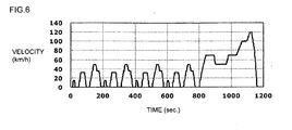
- Fig. 6 is a view showing a NEDC operation mode.
- partition wall 1: partition wall, 1a: first partition wall (thick wall), 1b: second partition wall (thin wall), 2: cell, 10: honeycomb catalyst article
- Fig. 1 is a perspective view showing an embodiment of a honeycomb catalyst article of the present invention
- Fig. 2 is an explanatory view showing the embodiment 1 on the end face on one side of the honeycomb catalyst article shown in Fig. 1
- the honeycomb catalyst article of the present embodiment is a honeycomb catalyst article 10 having a plurality of cells 2 formed of a plurality of partition walls 1 and extending through in parallel with one another between the two end faces S1 and S2.
- the partition walls 1 are formed of ceramic and the cells 2 are formed by the partition walls 1 including both the first partition walls 1a having the first thickness and the second partition walls 1b having the second thickness smaller than the first thickness.
- the inner peripheral portion of the honeycomb catalyst article 10 is constituted of the second partition walls 1b, and the outer peripheral portion surrounding the inner peripheral portion of the honeycomb catalyst article 10 is constituted of the first partition walls 1a.
- the ratio of the first partition wall region area constituted of the first partition walls 1a to the second partition wall region area constituted of the second partition walls 1b (first partition wall region area / second partition wall area) in a cross section perpendicular to a cell extension direction is 1 to 30, and a larger amount of catalyst is loaded on the first partition walls 1a than on the second partition walls 1b.
- the first partition wall region area is preferably larger than the second partition wall region area.
- the first partition wall region area / second partition wall area ratio is preferably 1 to 30, more preferably 1.7 to 8.
- the second partition wall region area becomes larger, temperature rises more easily. However, when the engine is stopped, temperature easily falls.
- the first partition wall region area (thick partition wall region) increases, it becomes harder to raise temperature, and temperature hardly falls when the engine is stopped. Therefore, a balance between temperature fall performance and temperature rise performance is important, and the aforementioned range is preferable.
- the first partition wall 1a in the outer peripheral portion has large thermal capacity, and the gas flow rate is low in the cells 2 surrounded by the first partition walls 1a to have slow temperature fall due to heat transfer, which improves heat retaining ability.
- the second partition walls 1b in the inner peripheral portion (central portion) has small thermal capacity, and the gas flow rate is high in the cells 2 surrounded by the second partition walls 1b to have fast temperature rise due to heat transfer, which improves temperature rise performance.
- the catalyst Since a larger amount of catalyst is loaded on the first partition walls 1a than on the second partition walls 1b, when it is used for exhaust gas purification of a diesel-powered automobile or the like, the catalyst is activated soon to be able to effectively purify exhaust gas even in the case of repeating the engine stop, start, and run. Further, since exhaust gas tends to flow more in the center of the honeycomb catalyst article 10, by having the second partition walls 1b (thin walls) in the central portion and the first partition walls 1a (thick walls) in the outer peripheral portion, the catalyst is easily activated soon after the engine is started.
- the thin partition wall 1b portion is first heated upon heating, and the temperature of the catalyst coated on the honeycomb catalyst article 10 quickly reaches the activation temperature.
- cooling of the thick partition walls 1a portions becomes slow to be able to lengthen the time that temperature of the catalyst is in the catalyst activation temperature range.
- the first partition walls 1a before loading of the catalyst, preferably have a thickness of 0.127 to 0.229 mm, and the second partition walls preferably have a thickness of 0.05 to 0.127 mm; and after loading of the catalyst, the first partition walls 1a preferably have a thickness of 0.19 to 0.282, and the second partition walls 1b preferably have a thickness of 0.081 to 0.166 mm.
- the thin walls become thinner, temperature rises more easily. However, when the engine is stopped, temperature easily falls. As the thick walls become thicker, it becomes more difficult to raise temperature. However, when the engine is stopped, temperature hardly falls. Therefore, a balance between the temperature fall performance and temperature rise performance is important, and the aforementioned ranges are preferable.
- the ratio of the thickness of the first partition walls 1a to the thickness of the second partition walls 1b is preferably 1.5 to 4.0.
- the ratio is below 1.5, the honeycomb catalyst article is close to a conventional honeycomb catalyst article having uniform partition wall thickness, and an effect in improving the temperature rise performance and the heat retaining ability is hardly obtained.
- the ratio is above 4,0, pressure loss in the cells 2 formed by the first partition walls 1a increases, and a pressure loss difference from the thin wall portion increases to make gas permeation region to a carrier uneven.
- the ratio of the thickness of the first partition walls to the thickness of the second partition walls (first partition wall thickness / second partition wall thickness) after the catalyst is loaded thereon is preferably 1 to 2.
- the honeycomb catalyst article 10 has a circular cross section perpendicular to the cell extension direction, and the second partition wall region has a circular shape with the central axis of the honeycomb catalyst article 10 as the center thereof.
- the area ratio ( ⁇ R 2 - ⁇ r 2 )/ ⁇ r 2 i.e., (R 2 -r 2 )/r 2 is preferably 1 to 30.
- the partition walls 1 constituting the honeycomb catalyst article 10 is constituted of at least one kind of ceramic selected from the group consisting of cordierite, alumina, mullite, and lithium aluminosilicate (LAS).
- the catalyst examples include an oxidation catalyst, a NOx adsorber reduction catalyst, a SCR catalyst, and a ternary catalyst.
- the catalyst coating amount is large in the thick wall portion (first partition walls 1a) of the outer peripheral portion and small in the thin wall portion (second partition walls 1b) of the inner peripheral portion. This increases heat generation due to the reactions of the following (1) and (2) in the portion having a large catalyst coating amount in comparison with that in the portion having a small catalyst coating amount to reduce the demerit of low temperature rise performance due to high thermal capacity in the thick wall portion.
- the catalyst layer may be made thinner than that of the general case. By such appropriate disposition of the catalyst, it contributes to reduction in the catalyst amount.
- the difference in the catalyst coat amount depending on the portion in the honeycomb can easily be obtained by varying the number of times of coating. For example, after the coating is first performed on the whole, a cover made of a rubber plate is arranged on a portion corresponding to the thinner wall portion of the inner peripheral portion, and the catalyst is coated on the remaining portion (portion corresponding to the thick wall portion of the outer peripheral portion) to obtain the difference in the coat amount.
- the catalyst used for coating enters inside the honeycomb, and, at the same time, the catalyst layer itself obtains a porous structure. In the thick coated catalyst layer, noble metal particles is held more on the porous surface per unit surface area of the honeycomb surface than in a portion where the coating is not thick.
- the catalyst coat amount is preferably 150 to 300 g/L. When it is below 150 g/L, the effect in improving the heat retaining ability and the temperature rise performance can not be obtained sufficiently. When it is above 300 g/L, clogging may easily be caused by the catalyst coat, or the noble metal may easily aggregate.
- the thin walls 1b are excellent in temperature rise performance to enable the temperature to quickly reach the catalyst activation temperature, and, during driving, since the thick walls 1a are excellent in heat retaining ability, it is possible to maintain the temperature in the catalyst activation region even in the case of frequent stop during a street run.
- Fig. 4 shows a honeycomb catalyst article 10 of the embodiment 2.
- the honeycomb catalyst article 10 of the embodiment 2 has a circular cross section perpendicular to the cell extension direction with the radius R, and the second partition wall region is formed to have a quadrangular shape with the central axis of the honeycomb catalyst article 10 as the center thereof. This constitution makes forming easy.
- Fig. 5 shows a honeycomb catalyst article 10 of the embodiment 3.
- the honeycomb catalyst article 10 of the embodiment 3 has an egg-shaped cross section perpendicular to the cell extension direction, and the second partition wall region is formed to have an egg shape in the inner peripheral portion of the honeycomb catalyst article 10 in a similar manner. This constitution enables temperature to uniformly transfer from the center.
- any of the honeycomb catalyst articles 10 described above can be used as a purification apparatus disposed in a former portion of the filter.
- it can be used as a honeycomb for a DOC (Diesel Oxidation Catalyst) by being disposed in a former portion of the filter of the purification apparatus of a diesel-powered automobile. Since the exhaust gas temperature of a diesel-powered automobile is low, there is a case that the catalyst loaded on the DOC does not work effectively.
- a technique to improve it a technique to realize early temperature rise and slow temperature fall is important, and a honeycomb catalyst article 10 of the present invention can quickly rise temperature and has heat retaining ability.
- a ternary catalyst used for a gasoline-powered automobile since early temperature rise and slow temperature fall can be realized, by the use of it as a purification apparatus for a gasoline-powered automobile, further exhaust gas cleaning can be realized.
- the temperature of the thin wall portion can quickly reach the catalyst activation temperature at engine start because the thin wall portion is excellent in temperature rising performance. This is because (1) the thin wall portion has a low gas inflow resistance to easily induce more combustion gas having heat than in a common article and (2) the thermal capacity is small because of the thinness to have excellent temperature rise in comparison with a common article. On the other hand, the thick wall portion has low inflow of combustion gas and relatively low temperature rise effect due to heat transfer from the gas. However, because of the large catalyst amount, the aforementioned decomposition reaction heat, also, can be used for temperature rise, which reduce the demerit of just thick walls having only large thermal capacity. Since the thin wall portion has a great merit due to the thinness, the required catalyst amount is not as much as in the thick wall portion, and the amount of the catalyst of noble metal can be reduced significantly.
- the thick wall portion is excellent in isothermal holding, even in the case of frequent stop during a street run (though gas temperature is low while idling, even while idling at a velocity of 0 after the start of driving in Fig. 6 ), the catalyst activation temperature can be maintained in a thick wall portion. This is the same phenomenon as the aforementioned case.
- the low temperature gas having a temperature fall effect hardly flows into the thick wall portion to have a low heat release effect, and heat generated by the aforementioned decomposition reaction of the components in the low temperature gas can effectively be used for maintaining the temperature because of the large catalyst amount.
- raw materials such as talc, kaolin, alumina, and silica were blended at a predetermined compounding ratio, and a binder, a surfactant, and water were added to them at a predetermined compounding ratio, followed by mixing them together to obtain kneaded clay.
- a binder, a surfactant, and water were added to them at a predetermined compounding ratio, followed by mixing them together to obtain kneaded clay.
- the particle size, the components, and the like finally influence onporosity, thermal expansion coefficient, and the like, they can suitably be selected by a person of ordinary skill in the art, and also the binder and the surfactant can suitably determined.
- Example 1 is an evaluation carrier where the inner peripheral portion is formed of the partition walls 1b (thin walls), while the outer peripheral portion surrounding the inner peripheral portion is formed of the partition walls 1a (thick walls).
- Table 1 shows the radius R of the honeycomb structure (catalyst article) and the radius r of the partition wall 1b portion (R and r respectively show a proportion the length. See Fig. 3 ). Further, Table 1 shows the ratio of the area of the partition walls 1a to the area of the partition walls 1b (first partition wall region area / second partition wall region area). Table 1 furthermore shows thickness of each of the partition walls and the ratio of the thickness of the partition walls 1a to the thickness of the partition walls 1b before loading of the catalyst (honeycomb structure) and after loading of the catalyst (honeycomb catalyst article 10).
- Comparative Examples 1 to 3 were manufactured with the R and the r shown in Table 1. Incidentally, each of Comparative Examples 1 and 2 was a honeycomb structure (catalyst article) having a uniform partition wall thickness. For example, “3 mil / 600 cpsi" of Comparative Example 1 shows that the partition wall thickness is 3 mil and that the cell density is 600 cpsi.
- the honeycomb catalyst article of each of Examples and Comparative Examples was disposed in an exhaust gas system of a 2 liter gasoline engine automobile, and, by the use of the gasoline engine automobile, driving was performed in NEDC operation mode shown in Fig. 6 to measure emission of harmful components contained in exhaust gas discharged for 1 mile run.
- As the harmful components hydrocarbon (HC) and nitrogen monoxide (NO) amounts (g) in the exhaust gas were measured.
- Example 3 and 4 were preferable because they had both the heat retaining ability and the temperature rise performance. That is, as the second partition wall region area (thin wall region) becomes larger, the temperature more easily rises and more easily falls. Inversely, as the first partition wall region area (thick wall region) becomes larger, the temperature more hardly rises and more hardly falls. Therefore, Examples 3 and 4, which had the best balance between the heat retaining ability and the temperature rise performance, showed the best purification efficiency.
- the ratio of the first partition wall thickness to the second partition wall thickness after loading of the catalyst is preferably 1 to 2.
- the ratio of the first partition wall thickness to the second partition wall thickness after loading of the catalyst is preferably 1.1 or more.
- increase of the catalyst thickness increases the amount of noble metal to be used, at the saturation point or more, where no further improvement in purification performance is shown, it is no use raising the ratio, and it is preferably 1.7 or less.
- a honeycomb catalyst article of the present invention is particularly effective for purifying exhaust gas from diesel engine, where exhaust gas temperature is relatively low and can effectively used as a substrate for a SCR (selective catalytic reduction) catalyst for purifying NOx in exhaust gas and as a diesel oxidation catalyst besides a honeycomb catalyst article for being disposed in a DPF former portion.
- SCR selective catalytic reduction
Landscapes
- Chemical & Material Sciences (AREA)
- Engineering & Computer Science (AREA)
- Chemical Kinetics & Catalysis (AREA)
- Combustion & Propulsion (AREA)
- Health & Medical Sciences (AREA)
- Materials Engineering (AREA)
- Mechanical Engineering (AREA)
- General Engineering & Computer Science (AREA)
- Biomedical Technology (AREA)
- Toxicology (AREA)
- Ceramic Engineering (AREA)
- Organic Chemistry (AREA)
- Environmental & Geological Engineering (AREA)
- Analytical Chemistry (AREA)
- General Chemical & Material Sciences (AREA)
- Oil, Petroleum & Natural Gas (AREA)
- Catalysts (AREA)
- Exhaust Gas Treatment By Means Of Catalyst (AREA)
- Exhaust Gas After Treatment (AREA)
Abstract
Description
- The present invention relates to a honeycomb catalyst article. More specifically, the present invention relates to a honeycomb catalyst article satisfying both quick temperature-rising ability and high thermal capacity at the same time and capable of effectively purifying exhaust gas discharged from a diesel engine or the like.
- In accordance with tightening of exhaust gas regulations regarding a diesel engine, there have been proposed various methods using a diesel particulate filter (DPF) for trapping particulate matter (PM) contained in exhaust gas from a diesel engine. Generally, there is employed a method where a catalyst for oxidizing PM is coated on a DPF, and a honeycomb structure having a catalyst coated thereon is mounted in a front portion of the DPF. In the honeycomb structure, by changing NO contained in exhaust gas to NO2, PM deposited in the DPF is combusted, or, by engine control, post injection is conducted to oxidize uncombusted fuel and raise exhaust gas temperature, thereby combusting PM deposited in the DPF for regeneration of the DPF.
- In order to smoothly combust PM deposited in a DPF for regeneration of the DPF, it is necessary to lengthen the time that the aforementioned catalyst coated on the honeycomb structure is at activation temperature as much as possible. However, a diesel engine has low exhaust gas temperature, and temperature of a honeycomb structure does not reach catalyst activation temperature in a low load condition. Even after high load driving, upon drastic transition to low load, temperature of the honeycomb structure rapidly falls and sometimes becomes lower than the catalyst activation temperature, which causes a problem of hindering combustion of PM and/or a problem of incompletion of compulsory regeneration.
- In view of the aforementioned problems, there has generally been performed quick raise of the temperature to the catalyst activation temperature by thinning the cell partition walls of the honeycomb structure, raising porosity, or the like, to decrease thermal capacity of the honeycomb structure and improve a temperature rise characteristic of the substrate.
- However, though decrease in thermal capacity of the substrate can improve the temperature rise characteristic and make temperature of the catalyst coated on the substrate rapidly reach the catalyst activation temperature, the temperature of the catalyst rapidly becomes lower than the catalyst activation temperature when exhaust gas temperature falls down. In addition, when the thermal capacity of the substrate is increased in order to inhibit temperature fall of the substrate upon the exhaust gas temperature fall, the temperature rise characteristic is deteriorated. Thus, a mutually incompatible relation is shown. That is, it has been difficult to lengthen the time that the catalyst coated on the honeycomb structure is at activation temperature only by changing the partition wall thickness or the porosity of the substrate simply to change the thermal capacity.
- In such circumstances, there is disclosed a honeycomb structure constituted of partition walls having two or more kinds of thickness (
JP-A-2007-289924 JP-A-2007-289924 - In addition, there is disclosed a honeycomb structure where the partition wall thickness of the cells from the outermost periphery to a predetermined position is different from that of the remaining cells located inside the aforementioned cells (Republication Patent
WO02/011884 - However, heretofore, exhaust gas temperature is low at the time of engine start or in a low load condition to sometimes become lower than the catalyst activation temperature. That is, though it is necessary to lengthen the time that the catalyst coated on the honeycomb structure is at activation temperature in order to keep high purification rate by the contact of exhaust gas with the catalyst, there caused depression in purification rate because of the temperature not reaching the catalyst activation temperature. When the thickness of the partition walls is decreased, they are easily cooled due to decrease in thermal capacity. When the thickness of the partition walls is increased, the temperature rise performance is deteriorated.
- In
JP-A-2007-289924 WO02/011884 - The present invention has been made in view of the aforementioned problems and aims to provide a honeycomb catalyst article satisfying both quick temperature-rising ability and high thermal capacity at the same time and capable of effectively purifying exhaust gas discharged from a diesel engine or the like.
- According to the present invention, there is provided the following honeycomb catalyst article.
- [1] A honeycomb catalyst article having a plurality of cells extending though in parallel with one another between two end faces and formed by a plurality of partition walls, wherein the cells are formed by the partition walls formed of ceramic and including first partition walls having a first thickness and second partition walls having a second thickness smaller than the first thickness, an inner peripheral portion of the honeycomb catalyst article is constituted of the second partition walls, an outer peripheral portion surrounding the inner peripheral portion of the honeycomb catalyst article is constituted of the first partition walls, a ratio of a first partition wall region area constituted of the first partition walls to a second partition wall region area constituted of the second partition walls (first partition wall region area /second partition wall area) in a cross section perpendicular to a cell extension direction is 1 to 30, and a larger amount of catalyst is loaded on the first partition walls than on the second partition walls.
- [2] The honeycomb catalyst article according to [1], wherein, before loading of the catalyst, the first partition walls have a thickness of 0.127 to 0.229 mm, and the second partition walls have a thickness of 0.05 to 0.127 mm.
- [3] The honeycomb catalyst article according to [1] or [2], wherein a ratio of the thickness of the first partition walls to the thickness of the second partition walls (first partition wall thickness / second partition wall thickness), both having the catalyst loaded thereon, is 1 to 2.
- [4] The honeycomb catalyst article according to any one of [1] to [3], wherein the honeycomb catalyst has a circular cross section perpendicular to the cell extension direction, and the second partition wall region has a circular shape with the central axis of the honeycomb catalyst article as the center thereof.
- In a honeycomb catalyst article of the present invention, the first partition walls in the outer peripheral portion has large thermal capacity, and the cells surrounded by the first partition walls have improved heat retaining ability, while the second partition walls in the inner peripheral portion (central portion) has low thermal capacity to improve temperature rise performance. Since a larger amount of catalyst is loaded on the first partition walls than on the second partition walls, when it is used for exhaust gas purification of a diesel-powered automobile or the like, the catalyst is activated soon to be able to effectively purify exhaust gas even in the case of frequently repeating the engine stop, start, and run.
- [
Fig. 1] Fig. 1 is a perspective view showing an embodiment of a honeycomb structure of the present invention. - [
Fig. 2] Fig. 2 is an explanatory view showing theembodiment 1 on the end face on one side of a honeycomb structure. - [
Fig. 3] Fig. 3 is an explanatory view showing a relation between the radius R of a honeycomb structure and the radius r of the second partition wall region area. - [
Fig. 4] Fig. 4 is an explanatory view showing theembodiment 2 on the end face on one side of a honeycomb structure. - [
Fig. 5] Fig. 5 is an explanatory view showing the embodiment 3 on the end face on one side of a honeycomb structure. - [
Fig. 6] Fig. 6 is a view showing a NEDC operation mode. - 1: partition wall, 1a: first partition wall (thick wall), 1b: second partition wall (thin wall), 2: cell, 10: honeycomb catalyst article
- Hereinbelow, embodiments of the present invention will be described with referring to drawings. However, the present invention is by no means limited to the following embodiments, and changes, modifications, and improvements may be made as long as they do not deviate from the scope of the invention.
-
Fig. 1 is a perspective view showing an embodiment of a honeycomb catalyst article of the present invention, andFig. 2 is an explanatory view showing theembodiment 1 on the end face on one side of the honeycomb catalyst article shown inFig. 1 . As shown inFig. 1 , the honeycomb catalyst article of the present embodiment is ahoneycomb catalyst article 10 having a plurality ofcells 2 formed of a plurality ofpartition walls 1 and extending through in parallel with one another between the two end faces S1 and S2. Thepartition walls 1 are formed of ceramic and thecells 2 are formed by thepartition walls 1 including both thefirst partition walls 1a having the first thickness and thesecond partition walls 1b having the second thickness smaller than the first thickness. The inner peripheral portion of thehoneycomb catalyst article 10 is constituted of thesecond partition walls 1b, and the outer peripheral portion surrounding the inner peripheral portion of thehoneycomb catalyst article 10 is constituted of thefirst partition walls 1a. The ratio of the first partition wall region area constituted of thefirst partition walls 1a to the second partition wall region area constituted of thesecond partition walls 1b (first partition wall region area / second partition wall area) in a cross section perpendicular to a cell extension direction is 1 to 30, and a larger amount of catalyst is loaded on thefirst partition walls 1a than on thesecond partition walls 1b. - The first partition wall region area is preferably larger than the second partition wall region area. Specifically, the first partition wall region area / second partition wall area ratio is preferably 1 to 30, more preferably 1.7 to 8. As the second partition wall region area (thin partition wall region) becomes larger, temperature rises more easily. However, when the engine is stopped, temperature easily falls. In addition, as the first partition wall region area (thick partition wall region) increases, it becomes harder to raise temperature, and temperature hardly falls when the engine is stopped. Therefore, a balance between temperature fall performance and temperature rise performance is important, and the aforementioned range is preferable.
- By such constitution, the
first partition wall 1a in the outer peripheral portion has large thermal capacity, and the gas flow rate is low in thecells 2 surrounded by thefirst partition walls 1a to have slow temperature fall due to heat transfer, which improves heat retaining ability. In addition, thesecond partition walls 1b in the inner peripheral portion (central portion) has small thermal capacity, and the gas flow rate is high in thecells 2 surrounded by thesecond partition walls 1b to have fast temperature rise due to heat transfer, which improves temperature rise performance. Since a larger amount of catalyst is loaded on thefirst partition walls 1a than on thesecond partition walls 1b, when it is used for exhaust gas purification of a diesel-powered automobile or the like, the catalyst is activated soon to be able to effectively purify exhaust gas even in the case of repeating the engine stop, start, and run. Further, since exhaust gas tends to flow more in the center of thehoneycomb catalyst article 10, by having thesecond partition walls 1b (thin walls) in the central portion and thefirst partition walls 1a (thick walls) in the outer peripheral portion, the catalyst is easily activated soon after the engine is started. - Therefore, by the constitution as described above, the
thin partition wall 1b portion is first heated upon heating, and the temperature of the catalyst coated on thehoneycomb catalyst article 10 quickly reaches the activation temperature. When the exhaust gas temperature falls, cooling of thethick partition walls 1a portions becomes slow to be able to lengthen the time that temperature of the catalyst is in the catalyst activation temperature range. - In a
honeycomb catalyst article 10 of the present invention, before loading of the catalyst, thefirst partition walls 1a preferably have a thickness of 0.127 to 0.229 mm, and the second partition walls preferably have a thickness of 0.05 to 0.127 mm; and after loading of the catalyst, thefirst partition walls 1a preferably have a thickness of 0.19 to 0.282, and thesecond partition walls 1b preferably have a thickness of 0.081 to 0.166 mm. As the thin walls become thinner, temperature rises more easily. However, when the engine is stopped, temperature easily falls. As the thick walls become thicker, it becomes more difficult to raise temperature. However, when the engine is stopped, temperature hardly falls. Therefore, a balance between the temperature fall performance and temperature rise performance is important, and the aforementioned ranges are preferable. - In a
honeycomb catalyst article 10 of the present invention, before loading of the catalyst, the ratio of the thickness of thefirst partition walls 1a to the thickness of thesecond partition walls 1b (first partition wall thickness / second partition wall thickness) is preferably 1.5 to 4.0. When the ratio is below 1.5, the honeycomb catalyst article is close to a conventional honeycomb catalyst article having uniform partition wall thickness, and an effect in improving the temperature rise performance and the heat retaining ability is hardly obtained. On the other hand, when the ratio is above 4,0, pressure loss in thecells 2 formed by thefirst partition walls 1a increases, and a pressure loss difference from the thin wall portion increases to make gas permeation region to a carrier uneven. In addition, the ratio of the thickness of the first partition walls to the thickness of the second partition walls (first partition wall thickness / second partition wall thickness) after the catalyst is loaded thereon is preferably 1 to 2. - The
honeycomb catalyst article 10 has a circular cross section perpendicular to the cell extension direction, and the second partition wall region has a circular shape with the central axis of thehoneycomb catalyst article 10 as the center thereof. As shown inFig. 3 , with the radius R of the circularhoneycomb catalyst article 10 and the radius r of the second partition wall region, the area ratio (πR2-πr2)/πr2, i.e., (R2-r2)/r2 is preferably 1 to 30. - In the present embodiment, the
partition walls 1 constituting thehoneycomb catalyst article 10 is constituted of at least one kind of ceramic selected from the group consisting of cordierite, alumina, mullite, and lithium aluminosilicate (LAS). - Examples of the catalyst include an oxidation catalyst, a NOx adsorber reduction catalyst, a SCR catalyst, and a ternary catalyst. The catalyst coating amount is large in the thick wall portion (
first partition walls 1a) of the outer peripheral portion and small in the thin wall portion (second partition walls 1b) of the inner peripheral portion. This increases heat generation due to the reactions of the following (1) and (2) in the portion having a large catalyst coating amount in comparison with that in the portion having a small catalyst coating amount to reduce the demerit of low temperature rise performance due to high thermal capacity in the thick wall portion. In addition, in the thin wall portion of the inner peripheral portion, since time spent for reaching the catalyst activity temperature range is short because of high temperature rise performance, the catalyst layer may be made thinner than that of the general case. By such appropriate disposition of the catalyst, it contributes to reduction in the catalyst amount. -


- The difference in the catalyst coat amount depending on the portion in the honeycomb can easily be obtained by varying the number of times of coating. For example, after the coating is first performed on the whole, a cover made of a rubber plate is arranged on a portion corresponding to the thinner wall portion of the inner peripheral portion, and the catalyst is coated on the remaining portion (portion corresponding to the thick wall portion of the outer peripheral portion) to obtain the difference in the coat amount. The catalyst used for coating enters inside the honeycomb, and, at the same time, the catalyst layer itself obtains a porous structure. In the thick coated catalyst layer, noble metal particles is held more on the porous surface per unit surface area of the honeycomb surface than in a portion where the coating is not thick.
- The catalyst coat amount is preferably 150 to 300 g/L. When it is below 150 g/L, the effect in improving the heat retaining ability and the temperature rise performance can not be obtained sufficiently. When it is above 300 g/L, clogging may easily be caused by the catalyst coat, or the noble metal may easily aggregate.
- By such constitution, at the engine start, the
thin walls 1b are excellent in temperature rise performance to enable the temperature to quickly reach the catalyst activation temperature, and, during driving, since thethick walls 1a are excellent in heat retaining ability, it is possible to maintain the temperature in the catalyst activation region even in the case of frequent stop during a street run. -
Fig. 4 shows ahoneycomb catalyst article 10 of theembodiment 2. Thehoneycomb catalyst article 10 of theembodiment 2 has a circular cross section perpendicular to the cell extension direction with the radius R, and the second partition wall region is formed to have a quadrangular shape with the central axis of thehoneycomb catalyst article 10 as the center thereof. This constitution makes forming easy. -
Fig. 5 shows ahoneycomb catalyst article 10 of the embodiment 3. Thehoneycomb catalyst article 10 of the embodiment 3 has an egg-shaped cross section perpendicular to the cell extension direction, and the second partition wall region is formed to have an egg shape in the inner peripheral portion of thehoneycomb catalyst article 10 in a similar manner. This constitution enables temperature to uniformly transfer from the center. - In addition, any of the
honeycomb catalyst articles 10 described above can be used as a purification apparatus disposed in a former portion of the filter. Specifically, it can be used as a honeycomb for a DOC (Diesel Oxidation Catalyst) by being disposed in a former portion of the filter of the purification apparatus of a diesel-powered automobile. Since the exhaust gas temperature of a diesel-powered automobile is low, there is a case that the catalyst loaded on the DOC does not work effectively. As a technique to improve it, a technique to realize early temperature rise and slow temperature fall is important, and ahoneycomb catalyst article 10 of the present invention can quickly rise temperature and has heat retaining ability. Also, in a ternary catalyst used for a gasoline-powered automobile, since early temperature rise and slow temperature fall can be realized, by the use of it as a purification apparatus for a gasoline-powered automobile, further exhaust gas cleaning can be realized. - The temperature of the thin wall portion can quickly reach the catalyst activation temperature at engine start because the thin wall portion is excellent in temperature rising performance. This is because (1) the thin wall portion has a low gas inflow resistance to easily induce more combustion gas having heat than in a common article and (2) the thermal capacity is small because of the thinness to have excellent temperature rise in comparison with a common article. On the other hand, the thick wall portion has low inflow of combustion gas and relatively low temperature rise effect due to heat transfer from the gas. However, because of the large catalyst amount, the aforementioned decomposition reaction heat, also, can be used for temperature rise, which reduce the demerit of just thick walls having only large thermal capacity. Since the thin wall portion has a great merit due to the thinness, the required catalyst amount is not as much as in the thick wall portion, and the amount of the catalyst of noble metal can be reduced significantly.
- In addition, since the thick wall portion is excellent in isothermal holding, even in the case of frequent stop during a street run (though gas temperature is low while idling, even while idling at a velocity of 0 after the start of driving in
Fig. 6 ), the catalyst activation temperature can be maintained in a thick wall portion. This is the same phenomenon as the aforementioned case. The low temperature gas having a temperature fall effect hardly flows into the thick wall portion to have a low heat release effect, and heat generated by the aforementioned decomposition reaction of the components in the low temperature gas can effectively be used for maintaining the temperature because of the large catalyst amount. Therefore, when driving is started after idling, temperature of the thin wall portion reaches the catalyst activation temperature very quickly, and the thick wall portion maintains relatively high temperature even during idling. Therefore, the function over the whole honeycomb catalyst article is exhibited in a very short period of time in comparison with a general article. - Hereinbelow, the present invention will be described in more detail on the basis of Examples. However, the present invention is by no means limited to the Examples.
- To obtain cordierite after firing, raw materials such as talc, kaolin, alumina, and silica were blended at a predetermined compounding ratio, and a binder, a surfactant, and water were added to them at a predetermined compounding ratio, followed by mixing them together to obtain kneaded clay. Regarding the cordierite forming raw material, though the particle size, the components, and the like finally influence onporosity, thermal expansion coefficient, and the like, they can suitably be selected by a person of ordinary skill in the art, and also the binder and the surfactant can suitably determined. The kneaded clay was subjected to extrusion forming using an extruder having a die where the slit width was adjusted in consideration of the shrinkage ratio in the drying and firing stages so as to obtain the cell structure shown in Table 1 after firing. Thus, there was manufactured a honeycomb structure having a diameter of 100 mm, a length of 120 mm, and an almost
square cell 2 shape after drying and firing (seeFig. 1 ). A ternary catalyst was loaded as the catalyst. Example 1 is an evaluation carrier where the inner peripheral portion is formed of thepartition walls 1b (thin walls), while the outer peripheral portion surrounding the inner peripheral portion is formed of thepartition walls 1a (thick walls). Table 1 shows the radius R of the honeycomb structure (catalyst article) and the radius r of thepartition wall 1b portion (R and r respectively show a proportion the length. SeeFig. 3 ). Further, Table 1 shows the ratio of the area of thepartition walls 1a to the area of thepartition walls 1b (first partition wall region area / second partition wall region area). Table 1 furthermore shows thickness of each of the partition walls and the ratio of the thickness of thepartition walls 1a to the thickness of thepartition walls 1b before loading of the catalyst (honeycomb structure) and after loading of the catalyst (honeycomb catalyst article 10). - Examples 2 to 6 and Comparative Examples 1 to 3 were manufactured with the R and the r shown in Table 1. Incidentally, each of Comparative Examples 1 and 2 was a honeycomb structure (catalyst article) having a uniform partition wall thickness. For example, "3 mil / 600 cpsi" of Comparative Example 1 shows that the partition wall thickness is 3 mil and that the cell density is 600 cpsi.
-
Table 1 - 1 Radius ratio Area ratio Before loading of catalyst R r First partition wall region area /second partition wall region area Thickness b of partition wall 1bThickness a of partition wall 1aRatio (a/b) (mm) (mm) Example 1 4 2.83 1.00 0.102 0.152 1.50 Example 2 5 3 1.78 0.102 0.152 1.50 Example 3 2 1 3.00 0.102 0.152 1.50 Example 4 3 1 8.00 0.102 0.152 1.50 Example 5 5 1 24.00 0.102 0.152 1.50 Comp. Ex. 1 1 1 0.00 3mil/600cpsi (0.0762mm/600cpsi) Comp. Ex. 2 1 1 0.00 4mil/600cpsi (0.1016mm/600cpsi) Comp. Ex. 3 10 9 0.23 0.102 0.152 1.50 Comp. Ex. 4 10 1 99.00 0.102 0.152 1.50 Table 1 - 2 After loading of catalyst Purification performance (g/mile) Thickness b of partition wall 1b (including catalyst layer)Thickness cb of catalyst layer on partition wall 1bThickness a of partition wall 1a (including catalyst layer)Thickness ca of catalyst partition layer on partition wall 1aRatio of wall thickness (a/b) HC NOx (mm) (mm) (mm) (mm) Example 1 0.137 0.036 0.193 0.041 1.41 0.22 0.46 Example 2 0.137 0.036 0.193 0.041 1.41 0.15 0.38 Example 3 0.137 0.036 0.193 0.041 1.41 0.1 0.31 Example 4 0.137 0.036 0.193 0.041 1.41 0.12 0.34 Example 5 0.137 0.036 0.193 0.041 1.41 0.26 0.43 Comp. Ex. 1 0.114 0.038 0.3 0.48 Comp. Ex. 2 0.140 0.038 0.35 0.54 Comp. Ex. 3 0.137 0.036 0.193 0.041 1.41 0.28 0.47 Comp. Ex. 4 0.137 0.036 0.193 0.041 1.41 0.33 0.46 - For the measurement of harmful component emission, the honeycomb catalyst article of each of Examples and Comparative Examples was disposed in an exhaust gas system of a 2 liter gasoline engine automobile, and, by the use of the gasoline engine automobile, driving was performed in NEDC operation mode shown in
Fig. 6 to measure emission of harmful components contained in exhaust gas discharged for 1 mile run. As the harmful components, hydrocarbon (HC) and nitrogen monoxide (NO) amounts (g) in the exhaust gas were measured. - The amounts of NOx and HC (uncombusted hydrocarbon) discharged from an engine of each of the evaluation carrier obtained by carrying out automobile evaluation are shown in Table 1 . The lower these values are, the higher the purification rates are. As shown in Table 1, Examples 3 and 4 were preferable because they had both the heat retaining ability and the temperature rise performance. That is, as the second partition wall region area (thin wall region) becomes larger, the temperature more easily rises and more easily falls. Inversely, as the first partition wall region area (thick wall region) becomes larger, the temperature more hardly rises and more hardly falls. Therefore, Examples 3 and 4, which had the best balance between the heat retaining ability and the temperature rise performance, showed the best purification efficiency.
- Next, in each of Examples 3 and 4, there was produced an evaluation carrier where the ratio of the radius R to the radius r was fixed, that is, the ratio of the area of the
partition walls 1a and the area of thepartition walls 1b (the first partition wall region area to the second partition wall region area) was fixed with changing the partition wall thickness. Table 2 shows R, r, and the partition wall thickness of each evaluation carrier. -
Table 2 - 1 Ratio of radius Area ratio Before loading of catalyst R r First partition wall region area / second partition wall region area Thickness b of partition wall 1bThickness a of partition wall 1aRatio (a/b) (mm) (mm) Example 1-1 4 2.83 1.00 0.051 0.203 4.00 Example 1-2 0.076 0.178 2.33 Example 1-3 0.102 0.152 1.50 Example 3-1 2 1 3.00 0.051 0.203 4.00 Example 3-2 0.076 0.178 2.33 Example 3-3 0.102 0.152 1.50 Example 3-4 0.127 0.152 1.20 Example 4-1 3 1 8.00 0.051 0.229 4.50 Example 4-2 0.051 0.203 4.00 Example 4-3 0.076 0.178 2.33 Example 4-4 0.102 0.152 1.50 Example 4-5 0.127 0.152 1.20 Comp. Ex. 1 1 1 3 mil / 600 cpsi (0.0762 mm / 600 cpsi) Comp. Ex. 2 1 1 4 mil / 600 cpsi (0.1016 mm / 600 cpsi) Table 2-2 After loading of catalyst Purification performance (g/mile) Thickness b of partition wall 1b (including catalyst layer)Thickness cb of catalyst layer on partition wall 1bThickness a of partition wall 1a (including catalyst layer)Thickness ca of catalyst layer on partition wall 1aRatio of partition wall thickness (a/b) Ratio of catalyst layer (ca/cb) HC NOx (mm) (mm) (mm) (mm) Example 1-1 0.081 0.031 0.25 0.048 3.093 1.58 0.21 0.47 Example 1-2 0.109 0.033 0.22 0.046 2.047 1.38 0.22 0.46 Example 1-3 0.137 0.036 0.19 0.041 1.407 1.14 0.25 0.48 Example 3-1 0.081 0.031 0.25 0.048 3.093 1.58 0.07 0.29 Example 3-2 0.109 0.033 0.22 0.046 20.47 1.38 0.10 0.31 Example 3-3 0.137 0.036 0.19 0.041 1.407 1.14 0.15 0.35 Example 3-4 0.165 0.038 0.19 0.041 1.169 1.07 0.26 0.41 Example 4-1 0.081 0.031 0.28 0.053 3.467 1.75 0.16 0.38 Example 4-2 0.081 0.031 0.25 0.048 3.093 1.58 0.17 0.38 Example 4-3 0.109 0.033 0.22 0.046 2.047 1.38 0.12 0.34 Example 4-4 0.137 0.036 0.19 0.041 1.407 1.14 0.18 0.39 Example 4-5 0.165 0.038 0.19 0.041 1.169 1.07 0.27 0.43 Comp. Ex. 1 0.114 0.038 0.30 0.48 Comp. Ex. 2 0.140 0.038 0.35 0.54 - The results of carrying out the automobile evaluation using these evaluation carriers are shown in Table 2. As the second partition wall region area (thin wall region) becomes larger, or as the thin wall becomes thinner, temperature more easily rises and more easily falls. Inversely, as the first partition wall region area (thick wall region) becomes larger, or the thick wall becomes thicker, temperature more hardly rises and more hardly falls. High purification efficiency was shown in Examples 3-1 to 3-3 and 4-1 to 4-4, which have a good balance between the heat retaining ability and the temperature rise performance. From these results, the ratio of the first partition wall thickness to the second partition wall thickness after loading of the catalyst is preferably 1 to 2. Further, since the implication of improvement is lacked unless the purification performance is higher by at least about 10% than that of common articles (Comparative Examples 1 and 2), the ratio of the first partition wall thickness to the second partition wall thickness after loading of the catalyst is preferably 1.1 or more. On the other hand, since increase of the catalyst thickness increases the amount of noble metal to be used, at the saturation point or more, where no further improvement in purification performance is shown, it is no use raising the ratio, and it is preferably 1.7 or less.
- A honeycomb catalyst article of the present invention is particularly effective for purifying exhaust gas from diesel engine, where exhaust gas temperature is relatively low and can effectively used as a substrate for a SCR (selective catalytic reduction) catalyst for purifying NOx in exhaust gas and as a diesel oxidation catalyst besides a honeycomb catalyst article for being disposed in a DPF former portion. In addition, also in a gasoline engine, where exhaust gas temperature is relatively high, it is effectively used for dealing with exhaust gas.
Claims (4)
- A honeycomb catalyst article having a plurality of cells extending though in parallel with one another between two end faces and formed by a plurality of partition walls,
wherein the cells are formed by the partition walls formed of ceramic and including first partition walls having a first thickness and second partition walls having a second thickness smaller than the first thickness,
an inner peripheral portion of the honeycomb catalyst article is constituted of the second partition walls,
an outer peripheral portion surrounding the inner peripheral portion of the honeycomb catalyst article is constituted of the first partition walls,
a ratio of a first partition wall region area constituted of the first partition walls to a second partition wall region area constituted of the second partition walls (first partition wall region area /second partition wall area) in a cross section perpendicular to a cell extension direction is 1 to 30, and
a larger amount of catalyst is loaded on the first partition walls than on the second partition walls. - The honeycomb catalyst article according to Claim 1, wherein, before loading of the catalyst, the first partition walls have a thickness of 0.127 to 0.229 mm, and the second partition walls have a thickness of 0.05 to 0.127 mm.
- The honeycomb catalyst article according to Claim 1 or 2, wherein a ratio of the thickness of the first partition walls to the thickness of the second partition walls (first partition wall thickness / second partition wall thickness), both having the catalyst loaded thereon, is 1 to 2.
- The honeycomb catalyst article according to any one of Claims 1 to 3, wherein the honeycomb catalyst has a circular cross section perpendicular to the cell extension direction, and the second partition wall region has a circular shape with the central axis of the honeycomb catalyst article as the center thereof.
Applications Claiming Priority (1)
| Application Number | Priority Date | Filing Date | Title |
|---|---|---|---|
| JP2009086950A JP5639343B2 (en) | 2009-03-31 | 2009-03-31 | Honeycomb catalyst body |
Publications (3)
| Publication Number | Publication Date |
|---|---|
| EP2236205A2 true EP2236205A2 (en) | 2010-10-06 |
| EP2236205A3 EP2236205A3 (en) | 2013-01-02 |
| EP2236205B1 EP2236205B1 (en) | 2018-04-25 |
Family
ID=42340657
Family Applications (1)
| Application Number | Title | Priority Date | Filing Date |
|---|---|---|---|
| EP10250436.2A Active EP2236205B1 (en) | 2009-03-31 | 2010-03-10 | Honeycomb Catalyst article |
Country Status (2)
| Country | Link |
|---|---|
| EP (1) | EP2236205B1 (en) |
| JP (1) | JP5639343B2 (en) |
Cited By (6)
| Publication number | Priority date | Publication date | Assignee | Title |
|---|---|---|---|---|
| EP2419212A4 (en) * | 2009-04-17 | 2014-06-18 | Basf Corp | MULTIZONE CATALYST COMPOSITIONS |
| EP2853708A1 (en) * | 2013-09-26 | 2015-04-01 | NGK Insulators, Ltd. | Honeycomb structure |
| US9447716B2 (en) | 2012-03-30 | 2016-09-20 | Ngk Insulators, Ltd. | Honeycomb structure |
| CN109944662A (en) * | 2019-03-25 | 2019-06-28 | 山东国瓷功能材料股份有限公司 | Honeycomb Structure Body and Honeycomb Structure Filter |
| GB2581776B (en) * | 2019-02-19 | 2022-08-17 | Jaguar Land Rover Ltd | Catalytic converter core having first and second regions with different thermal inertia |
| US11911723B2 (en) | 2019-03-25 | 2024-02-27 | Shandong Sinocera Functional Material Co., Ltd | Honeycomb structure body, honeycomb structure filter, and extrusion molding die |
Families Citing this family (8)
| Publication number | Priority date | Publication date | Assignee | Title |
|---|---|---|---|---|
| WO2011114511A1 (en) * | 2010-03-19 | 2011-09-22 | イビデン株式会社 | Honeycomb structure |
| JP5478309B2 (en) * | 2010-03-23 | 2014-04-23 | 日本碍子株式会社 | Honeycomb structure |
| JP5730631B2 (en) * | 2011-03-23 | 2015-06-10 | 日本碍子株式会社 | Honeycomb structure |
| JP6174500B2 (en) * | 2014-02-04 | 2017-08-02 | 日本碍子株式会社 | Honeycomb structure |
| JP6792489B2 (en) * | 2017-03-07 | 2020-11-25 | 日本碍子株式会社 | Honeycomb structure |
| JP6570678B2 (en) * | 2018-02-27 | 2019-09-04 | 本田技研工業株式会社 | Filter carrier |
| JP2021133283A (en) * | 2020-02-25 | 2021-09-13 | 日本碍子株式会社 | Honeycomb filter |
| WO2025258401A1 (en) * | 2024-06-10 | 2025-12-18 | 日本碍子株式会社 | Honeycomb structure and gas recovery device |
Citations (2)
| Publication number | Priority date | Publication date | Assignee | Title |
|---|---|---|---|---|
| WO2002011884A1 (en) | 2000-08-03 | 2002-02-14 | Ngk Insulators, Ltd. | Ceramic honeycomb structure |
| JP2007289924A (en) | 2006-03-29 | 2007-11-08 | Ngk Insulators Ltd | Honeycomb structure |
Family Cites Families (8)
| Publication number | Priority date | Publication date | Assignee | Title |
|---|---|---|---|---|
| DE3912915C1 (en) * | 1989-04-20 | 1990-12-13 | Degussa Ag, 6000 Frankfurt, De | |
| JPH0813337B2 (en) * | 1989-11-04 | 1996-02-14 | 日本碍子株式会社 | Ceramic honeycomb structure and method for manufacturing the same |
| JPH04231614A (en) * | 1990-12-27 | 1992-08-20 | Toyota Autom Loom Works Ltd | Exhaust gas purifying device of diesel engine |
| JP3526084B2 (en) * | 1993-12-28 | 2004-05-10 | 日本碍子株式会社 | Adsorption / catalyst for exhaust gas purification, adsorbent, exhaust gas purification system and exhaust gas purification method |
| JP2002177794A (en) * | 2000-09-29 | 2002-06-25 | Denso Corp | Ceramic catalyst body and ceramic carrier |
| JP4459476B2 (en) * | 2001-05-01 | 2010-04-28 | 日本碍子株式会社 | Porous honeycomb structure and manufacturing method thereof |
| JP5052717B2 (en) * | 2001-05-02 | 2012-10-17 | 日本碍子株式会社 | Honeycomb structure, and honeycomb filter and converter system using the same |
| JP2003010616A (en) * | 2001-06-29 | 2003-01-14 | Ngk Insulators Ltd | Honeycomb structure |
-
2009
- 2009-03-31 JP JP2009086950A patent/JP5639343B2/en active Active
-
2010
- 2010-03-10 EP EP10250436.2A patent/EP2236205B1/en active Active
Patent Citations (2)
| Publication number | Priority date | Publication date | Assignee | Title |
|---|---|---|---|---|
| WO2002011884A1 (en) | 2000-08-03 | 2002-02-14 | Ngk Insulators, Ltd. | Ceramic honeycomb structure |
| JP2007289924A (en) | 2006-03-29 | 2007-11-08 | Ngk Insulators Ltd | Honeycomb structure |
Cited By (7)
| Publication number | Priority date | Publication date | Assignee | Title |
|---|---|---|---|---|
| EP2419212A4 (en) * | 2009-04-17 | 2014-06-18 | Basf Corp | MULTIZONE CATALYST COMPOSITIONS |
| US9447716B2 (en) | 2012-03-30 | 2016-09-20 | Ngk Insulators, Ltd. | Honeycomb structure |
| EP2853708A1 (en) * | 2013-09-26 | 2015-04-01 | NGK Insulators, Ltd. | Honeycomb structure |
| US9663408B2 (en) | 2013-09-26 | 2017-05-30 | Ngk Insulators, Ltd. | Honeycomb structure |
| GB2581776B (en) * | 2019-02-19 | 2022-08-17 | Jaguar Land Rover Ltd | Catalytic converter core having first and second regions with different thermal inertia |
| CN109944662A (en) * | 2019-03-25 | 2019-06-28 | 山东国瓷功能材料股份有限公司 | Honeycomb Structure Body and Honeycomb Structure Filter |
| US11911723B2 (en) | 2019-03-25 | 2024-02-27 | Shandong Sinocera Functional Material Co., Ltd | Honeycomb structure body, honeycomb structure filter, and extrusion molding die |
Also Published As
| Publication number | Publication date |
|---|---|
| EP2236205B1 (en) | 2018-04-25 |
| JP5639343B2 (en) | 2014-12-10 |
| JP2010234316A (en) | 2010-10-21 |
| EP2236205A3 (en) | 2013-01-02 |
Similar Documents
| Publication | Publication Date | Title |
|---|---|---|
| EP2236205A2 (en) | Honeycomb Catalyst article | |
| JP5368959B2 (en) | Exhaust gas treatment equipment | |
| EP2324904B1 (en) | Catalyst-carrying filter and exhaust gas purification system | |
| US7204965B2 (en) | Filter catalyst for purifying exhaust gases | |
| EP2176534B1 (en) | Regeneration method for ceramic honeycomb structures | |
| KR102292153B1 (en) | Three-way catalytic converter | |
| US20080311340A1 (en) | Honeycomb structure and production method thereof | |
| EP1840347A1 (en) | Honeycomb structure | |
| EP1870573B1 (en) | Diesel particulate filter having improved thermal durability | |
| EP2692406A1 (en) | Sealed honeycomb structure, and exhaust gas purification device | |
| US8721978B2 (en) | Catalyst carrier | |
| US7429416B2 (en) | Honeycomb structure | |
| EP1820946A2 (en) | Honeycomb filter | |
| US7572497B2 (en) | Honeycomb structure | |
| US10105696B2 (en) | Honeycomb structure | |
| EP2221098B2 (en) | Honeycomb structure | |
| US8137637B2 (en) | Particulate filter and method of making | |
| EP2246107B1 (en) | Honeycomb structure | |
| EP2368621B1 (en) | Honeycomb structure | |
| JP7321258B2 (en) | Honeycomb body having a series of passages with different hydraulic diameters and its manufacturing method | |
| EP2626123A1 (en) | Plugged honeycomb structure and honeycomb catalyst body using the same | |
| JP5478309B2 (en) | Honeycomb structure | |
| JP4803480B2 (en) | Ceramic honeycomb filter | |
| WO2020101966A1 (en) | Honeycomb bodies having an array of through channels with a range of hydraulic diameters | |
| JPWO2002084085A1 (en) | Particulate filter and particulate removal method |
Legal Events
| Date | Code | Title | Description |
|---|---|---|---|
| PUAI | Public reference made under article 153(3) epc to a published international application that has entered the european phase |
Free format text: ORIGINAL CODE: 0009012 |
|
| AK | Designated contracting states |
Kind code of ref document: A2 Designated state(s): AT BE BG CH CY CZ DE DK EE ES FI FR GB GR HR HU IE IS IT LI LT LU LV MC MK MT NL NO PL PT RO SE SI SK SM TR |
|
| AX | Request for extension of the european patent |
Extension state: AL BA ME RS |
|
| PUAL | Search report despatched |
Free format text: ORIGINAL CODE: 0009013 |
|
| AK | Designated contracting states |
Kind code of ref document: A3 Designated state(s): AT BE BG CH CY CZ DE DK EE ES FI FR GB GR HR HU IE IS IT LI LT LU LV MC MK MT NL NO PL PT RO SE SI SK SM TR |
|
| AX | Request for extension of the european patent |
Extension state: AL BA ME RS |
|
| RIC1 | Information provided on ipc code assigned before grant |
Ipc: B01J 35/04 20060101AFI20121129BHEP Ipc: F01N 3/022 20060101ALI20121129BHEP Ipc: F01N 3/28 20060101ALI20121129BHEP Ipc: B01D 53/94 20060101ALI20121129BHEP Ipc: F01N 3/10 20060101ALI20121129BHEP |
|
| 17P | Request for examination filed |
Effective date: 20130621 |
|
| RBV | Designated contracting states (corrected) |
Designated state(s): AT BE BG CH CY CZ DE DK EE ES FI FR GB GR HR HU IE IS IT LI LT LU LV MC MK MT NL NO PL PT RO SE SI SK SM TR |
|
| 17Q | First examination report despatched |
Effective date: 20130917 |
|
| GRAP | Despatch of communication of intention to grant a patent |
Free format text: ORIGINAL CODE: EPIDOSNIGR1 |
|
| STAA | Information on the status of an ep patent application or granted ep patent |
Free format text: STATUS: GRANT OF PATENT IS INTENDED |
|
| INTG | Intention to grant announced |
Effective date: 20171006 |
|
| GRAS | Grant fee paid |
Free format text: ORIGINAL CODE: EPIDOSNIGR3 |
|
| GRAA | (expected) grant |
Free format text: ORIGINAL CODE: 0009210 |
|
| STAA | Information on the status of an ep patent application or granted ep patent |
Free format text: STATUS: THE PATENT HAS BEEN GRANTED |
|
| AK | Designated contracting states |
Kind code of ref document: B1 Designated state(s): AT BE BG CH CY CZ DE DK EE ES FI FR GB GR HR HU IE IS IT LI LT LU LV MC MK MT NL NO PL PT RO SE SI SK SM TR |
|
| REG | Reference to a national code |
Ref country code: GB Ref legal event code: FG4D |
|
| REG | Reference to a national code |
Ref country code: CH Ref legal event code: EP |
|
| REG | Reference to a national code |
Ref country code: AT Ref legal event code: REF Ref document number: 992303 Country of ref document: AT Kind code of ref document: T Effective date: 20180515 |
|
| REG | Reference to a national code |
Ref country code: IE Ref legal event code: FG4D |
|
| REG | Reference to a national code |
Ref country code: DE Ref legal event code: R096 Ref document number: 602010050155 Country of ref document: DE |
|
| REG | Reference to a national code |
Ref country code: NL Ref legal event code: MP Effective date: 20180425 |
|
| REG | Reference to a national code |
Ref country code: LT Ref legal event code: MG4D |
|
| PG25 | Lapsed in a contracting state [announced via postgrant information from national office to epo] |
Ref country code: NL Free format text: LAPSE BECAUSE OF FAILURE TO SUBMIT A TRANSLATION OF THE DESCRIPTION OR TO PAY THE FEE WITHIN THE PRESCRIBED TIME-LIMIT Effective date: 20180425 |
|
| PG25 | Lapsed in a contracting state [announced via postgrant information from national office to epo] |
Ref country code: BG Free format text: LAPSE BECAUSE OF FAILURE TO SUBMIT A TRANSLATION OF THE DESCRIPTION OR TO PAY THE FEE WITHIN THE PRESCRIBED TIME-LIMIT Effective date: 20180725 Ref country code: NO Free format text: LAPSE BECAUSE OF FAILURE TO SUBMIT A TRANSLATION OF THE DESCRIPTION OR TO PAY THE FEE WITHIN THE PRESCRIBED TIME-LIMIT Effective date: 20180725 Ref country code: FI Free format text: LAPSE BECAUSE OF FAILURE TO SUBMIT A TRANSLATION OF THE DESCRIPTION OR TO PAY THE FEE WITHIN THE PRESCRIBED TIME-LIMIT Effective date: 20180425 Ref country code: SE Free format text: LAPSE BECAUSE OF FAILURE TO SUBMIT A TRANSLATION OF THE DESCRIPTION OR TO PAY THE FEE WITHIN THE PRESCRIBED TIME-LIMIT Effective date: 20180425 Ref country code: PL Free format text: LAPSE BECAUSE OF FAILURE TO SUBMIT A TRANSLATION OF THE DESCRIPTION OR TO PAY THE FEE WITHIN THE PRESCRIBED TIME-LIMIT Effective date: 20180425 Ref country code: LT Free format text: LAPSE BECAUSE OF FAILURE TO SUBMIT A TRANSLATION OF THE DESCRIPTION OR TO PAY THE FEE WITHIN THE PRESCRIBED TIME-LIMIT Effective date: 20180425 Ref country code: ES Free format text: LAPSE BECAUSE OF FAILURE TO SUBMIT A TRANSLATION OF THE DESCRIPTION OR TO PAY THE FEE WITHIN THE PRESCRIBED TIME-LIMIT Effective date: 20180425 |
|
| PG25 | Lapsed in a contracting state [announced via postgrant information from national office to epo] |
Ref country code: LV Free format text: LAPSE BECAUSE OF FAILURE TO SUBMIT A TRANSLATION OF THE DESCRIPTION OR TO PAY THE FEE WITHIN THE PRESCRIBED TIME-LIMIT Effective date: 20180425 Ref country code: HR Free format text: LAPSE BECAUSE OF FAILURE TO SUBMIT A TRANSLATION OF THE DESCRIPTION OR TO PAY THE FEE WITHIN THE PRESCRIBED TIME-LIMIT Effective date: 20180425 Ref country code: GR Free format text: LAPSE BECAUSE OF FAILURE TO SUBMIT A TRANSLATION OF THE DESCRIPTION OR TO PAY THE FEE WITHIN THE PRESCRIBED TIME-LIMIT Effective date: 20180726 |
|
| REG | Reference to a national code |
Ref country code: AT Ref legal event code: MK05 Ref document number: 992303 Country of ref document: AT Kind code of ref document: T Effective date: 20180425 |
|
| PG25 | Lapsed in a contracting state [announced via postgrant information from national office to epo] |
Ref country code: PT Free format text: LAPSE BECAUSE OF FAILURE TO SUBMIT A TRANSLATION OF THE DESCRIPTION OR TO PAY THE FEE WITHIN THE PRESCRIBED TIME-LIMIT Effective date: 20180827 |
|
| REG | Reference to a national code |
Ref country code: DE Ref legal event code: R097 Ref document number: 602010050155 Country of ref document: DE |
|
| PG25 | Lapsed in a contracting state [announced via postgrant information from national office to epo] |
Ref country code: AT Free format text: LAPSE BECAUSE OF FAILURE TO SUBMIT A TRANSLATION OF THE DESCRIPTION OR TO PAY THE FEE WITHIN THE PRESCRIBED TIME-LIMIT Effective date: 20180425 Ref country code: DK Free format text: LAPSE BECAUSE OF FAILURE TO SUBMIT A TRANSLATION OF THE DESCRIPTION OR TO PAY THE FEE WITHIN THE PRESCRIBED TIME-LIMIT Effective date: 20180425 Ref country code: CZ Free format text: LAPSE BECAUSE OF FAILURE TO SUBMIT A TRANSLATION OF THE DESCRIPTION OR TO PAY THE FEE WITHIN THE PRESCRIBED TIME-LIMIT Effective date: 20180425 Ref country code: RO Free format text: LAPSE BECAUSE OF FAILURE TO SUBMIT A TRANSLATION OF THE DESCRIPTION OR TO PAY THE FEE WITHIN THE PRESCRIBED TIME-LIMIT Effective date: 20180425 Ref country code: EE Free format text: LAPSE BECAUSE OF FAILURE TO SUBMIT A TRANSLATION OF THE DESCRIPTION OR TO PAY THE FEE WITHIN THE PRESCRIBED TIME-LIMIT Effective date: 20180425 Ref country code: SK Free format text: LAPSE BECAUSE OF FAILURE TO SUBMIT A TRANSLATION OF THE DESCRIPTION OR TO PAY THE FEE WITHIN THE PRESCRIBED TIME-LIMIT Effective date: 20180425 |
|
| PG25 | Lapsed in a contracting state [announced via postgrant information from national office to epo] |
Ref country code: SM Free format text: LAPSE BECAUSE OF FAILURE TO SUBMIT A TRANSLATION OF THE DESCRIPTION OR TO PAY THE FEE WITHIN THE PRESCRIBED TIME-LIMIT Effective date: 20180425 Ref country code: IT Free format text: LAPSE BECAUSE OF FAILURE TO SUBMIT A TRANSLATION OF THE DESCRIPTION OR TO PAY THE FEE WITHIN THE PRESCRIBED TIME-LIMIT Effective date: 20180425 |
|
| PLBE | No opposition filed within time limit |
Free format text: ORIGINAL CODE: 0009261 |
|
| STAA | Information on the status of an ep patent application or granted ep patent |
Free format text: STATUS: NO OPPOSITION FILED WITHIN TIME LIMIT |
|
| 26N | No opposition filed |
Effective date: 20190128 |
|
| PG25 | Lapsed in a contracting state [announced via postgrant information from national office to epo] |
Ref country code: SI Free format text: LAPSE BECAUSE OF FAILURE TO SUBMIT A TRANSLATION OF THE DESCRIPTION OR TO PAY THE FEE WITHIN THE PRESCRIBED TIME-LIMIT Effective date: 20180425 |
|
| PG25 | Lapsed in a contracting state [announced via postgrant information from national office to epo] |
Ref country code: MC Free format text: LAPSE BECAUSE OF FAILURE TO SUBMIT A TRANSLATION OF THE DESCRIPTION OR TO PAY THE FEE WITHIN THE PRESCRIBED TIME-LIMIT Effective date: 20180425 |
|
| REG | Reference to a national code |
Ref country code: CH Ref legal event code: PL |
|
| GBPC | Gb: european patent ceased through non-payment of renewal fee |
Effective date: 20190310 |
|
| PG25 | Lapsed in a contracting state [announced via postgrant information from national office to epo] |
Ref country code: LU Free format text: LAPSE BECAUSE OF NON-PAYMENT OF DUE FEES Effective date: 20190310 |
|
| REG | Reference to a national code |
Ref country code: BE Ref legal event code: MM Effective date: 20190331 |
|
| PG25 | Lapsed in a contracting state [announced via postgrant information from national office to epo] |
Ref country code: GB Free format text: LAPSE BECAUSE OF NON-PAYMENT OF DUE FEES Effective date: 20190310 Ref country code: CH Free format text: LAPSE BECAUSE OF NON-PAYMENT OF DUE FEES Effective date: 20190331 Ref country code: LI Free format text: LAPSE BECAUSE OF NON-PAYMENT OF DUE FEES Effective date: 20190331 Ref country code: IE Free format text: LAPSE BECAUSE OF NON-PAYMENT OF DUE FEES Effective date: 20190310 |
|
| PG25 | Lapsed in a contracting state [announced via postgrant information from national office to epo] |
Ref country code: BE Free format text: LAPSE BECAUSE OF NON-PAYMENT OF DUE FEES Effective date: 20190331 Ref country code: FR Free format text: LAPSE BECAUSE OF NON-PAYMENT OF DUE FEES Effective date: 20190331 |
|
| PG25 | Lapsed in a contracting state [announced via postgrant information from national office to epo] |
Ref country code: TR Free format text: LAPSE BECAUSE OF FAILURE TO SUBMIT A TRANSLATION OF THE DESCRIPTION OR TO PAY THE FEE WITHIN THE PRESCRIBED TIME-LIMIT Effective date: 20180425 |
|
| PG25 | Lapsed in a contracting state [announced via postgrant information from national office to epo] |
Ref country code: MT Free format text: LAPSE BECAUSE OF NON-PAYMENT OF DUE FEES Effective date: 20190310 |
|
| PG25 | Lapsed in a contracting state [announced via postgrant information from national office to epo] |
Ref country code: CY Free format text: LAPSE BECAUSE OF FAILURE TO SUBMIT A TRANSLATION OF THE DESCRIPTION OR TO PAY THE FEE WITHIN THE PRESCRIBED TIME-LIMIT Effective date: 20180425 |
|
| PG25 | Lapsed in a contracting state [announced via postgrant information from national office to epo] |
Ref country code: IS Free format text: LAPSE BECAUSE OF FAILURE TO SUBMIT A TRANSLATION OF THE DESCRIPTION OR TO PAY THE FEE WITHIN THE PRESCRIBED TIME-LIMIT Effective date: 20180825 |
|
| PG25 | Lapsed in a contracting state [announced via postgrant information from national office to epo] |
Ref country code: HU Free format text: LAPSE BECAUSE OF FAILURE TO SUBMIT A TRANSLATION OF THE DESCRIPTION OR TO PAY THE FEE WITHIN THE PRESCRIBED TIME-LIMIT; INVALID AB INITIO Effective date: 20100310 |
|
| PG25 | Lapsed in a contracting state [announced via postgrant information from national office to epo] |
Ref country code: MK Free format text: LAPSE BECAUSE OF FAILURE TO SUBMIT A TRANSLATION OF THE DESCRIPTION OR TO PAY THE FEE WITHIN THE PRESCRIBED TIME-LIMIT Effective date: 20180425 |
|
| REG | Reference to a national code |
Ref country code: DE Ref legal event code: R079 Ref document number: 602010050155 Country of ref document: DE Free format text: PREVIOUS MAIN CLASS: B01J0035040000 Ipc: B01J0035560000 |
|
| PGFP | Annual fee paid to national office [announced via postgrant information from national office to epo] |
Ref country code: DE Payment date: 20260128 Year of fee payment: 17 |