EP2236066A2 - Adjustable solar-power unit for a dispenser - Google Patents
Adjustable solar-power unit for a dispenser Download PDFInfo
- Publication number
- EP2236066A2 EP2236066A2 EP10158441A EP10158441A EP2236066A2 EP 2236066 A2 EP2236066 A2 EP 2236066A2 EP 10158441 A EP10158441 A EP 10158441A EP 10158441 A EP10158441 A EP 10158441A EP 2236066 A2 EP2236066 A2 EP 2236066A2
- Authority
- EP
- European Patent Office
- Prior art keywords
- dispenser
- holder
- solar
- power
- sections
- Prior art date
- Legal status (The legal status is an assumption and is not a legal conclusion. Google has not performed a legal analysis and makes no representation as to the accuracy of the status listed.)
- Granted
Links
Images




Classifications
-
- H—ELECTRICITY
- H02—GENERATION; CONVERSION OR DISTRIBUTION OF ELECTRIC POWER
- H02S—GENERATION OF ELECTRIC POWER BY CONVERSION OF INFRARED RADIATION, VISIBLE LIGHT OR ULTRAVIOLET LIGHT, e.g. USING PHOTOVOLTAIC [PV] MODULES
- H02S20/00—Supporting structures for PV modules
- H02S20/30—Supporting structures being movable or adjustable, e.g. for angle adjustment
-
- A—HUMAN NECESSITIES
- A47—FURNITURE; DOMESTIC ARTICLES OR APPLIANCES; COFFEE MILLS; SPICE MILLS; SUCTION CLEANERS IN GENERAL
- A47K—SANITARY EQUIPMENT; ACCESSORIES THEREFOR, e.g. TOILET ACCESSORIES
- A47K5/00—Holders or dispensers for soap, toothpaste or the like
- A47K5/06—Dispensers for soap
- A47K5/12—Dispensers for soap for liquid or pasty soap
-
- F—MECHANICAL ENGINEERING; LIGHTING; HEATING; WEAPONS; BLASTING
- F24—HEATING; RANGES; VENTILATING
- F24S—SOLAR HEAT COLLECTORS; SOLAR HEAT SYSTEMS
- F24S30/00—Arrangements for moving or orienting solar heat collector modules
- F24S30/40—Arrangements for moving or orienting solar heat collector modules for rotary movement
- F24S30/42—Arrangements for moving or orienting solar heat collector modules for rotary movement with only one rotation axis
- F24S30/425—Horizontal axis
-
- H—ELECTRICITY
- H02—GENERATION; CONVERSION OR DISTRIBUTION OF ELECTRIC POWER
- H02S—GENERATION OF ELECTRIC POWER BY CONVERSION OF INFRARED RADIATION, VISIBLE LIGHT OR ULTRAVIOLET LIGHT, e.g. USING PHOTOVOLTAIC [PV] MODULES
- H02S20/00—Supporting structures for PV modules
- H02S20/20—Supporting structures directly fixed to an immovable object
-
- H—ELECTRICITY
- H02—GENERATION; CONVERSION OR DISTRIBUTION OF ELECTRIC POWER
- H02S—GENERATION OF ELECTRIC POWER BY CONVERSION OF INFRARED RADIATION, VISIBLE LIGHT OR ULTRAVIOLET LIGHT, e.g. USING PHOTOVOLTAIC [PV] MODULES
- H02S40/00—Components or accessories in combination with PV modules, not provided for in groups H02S10/00 - H02S30/00
- H02S40/30—Electrical components
- H02S40/38—Energy storage means, e.g. batteries, structurally associated with PV modules
-
- Y—GENERAL TAGGING OF NEW TECHNOLOGICAL DEVELOPMENTS; GENERAL TAGGING OF CROSS-SECTIONAL TECHNOLOGIES SPANNING OVER SEVERAL SECTIONS OF THE IPC; TECHNICAL SUBJECTS COVERED BY FORMER USPC CROSS-REFERENCE ART COLLECTIONS [XRACs] AND DIGESTS
- Y02—TECHNOLOGIES OR APPLICATIONS FOR MITIGATION OR ADAPTATION AGAINST CLIMATE CHANGE
- Y02E—REDUCTION OF GREENHOUSE GAS [GHG] EMISSIONS, RELATED TO ENERGY GENERATION, TRANSMISSION OR DISTRIBUTION
- Y02E10/00—Energy generation through renewable energy sources
- Y02E10/40—Solar thermal energy, e.g. solar towers
- Y02E10/46—Conversion of thermal power into mechanical power, e.g. Rankine, Stirling or solar thermal engines
-
- Y—GENERAL TAGGING OF NEW TECHNOLOGICAL DEVELOPMENTS; GENERAL TAGGING OF CROSS-SECTIONAL TECHNOLOGIES SPANNING OVER SEVERAL SECTIONS OF THE IPC; TECHNICAL SUBJECTS COVERED BY FORMER USPC CROSS-REFERENCE ART COLLECTIONS [XRACs] AND DIGESTS
- Y02—TECHNOLOGIES OR APPLICATIONS FOR MITIGATION OR ADAPTATION AGAINST CLIMATE CHANGE
- Y02E—REDUCTION OF GREENHOUSE GAS [GHG] EMISSIONS, RELATED TO ENERGY GENERATION, TRANSMISSION OR DISTRIBUTION
- Y02E10/00—Energy generation through renewable energy sources
- Y02E10/40—Solar thermal energy, e.g. solar towers
- Y02E10/47—Mountings or tracking
-
- Y—GENERAL TAGGING OF NEW TECHNOLOGICAL DEVELOPMENTS; GENERAL TAGGING OF CROSS-SECTIONAL TECHNOLOGIES SPANNING OVER SEVERAL SECTIONS OF THE IPC; TECHNICAL SUBJECTS COVERED BY FORMER USPC CROSS-REFERENCE ART COLLECTIONS [XRACs] AND DIGESTS
- Y02—TECHNOLOGIES OR APPLICATIONS FOR MITIGATION OR ADAPTATION AGAINST CLIMATE CHANGE
- Y02E—REDUCTION OF GREENHOUSE GAS [GHG] EMISSIONS, RELATED TO ENERGY GENERATION, TRANSMISSION OR DISTRIBUTION
- Y02E10/00—Energy generation through renewable energy sources
- Y02E10/50—Photovoltaic [PV] energy
-
- Y—GENERAL TAGGING OF NEW TECHNOLOGICAL DEVELOPMENTS; GENERAL TAGGING OF CROSS-SECTIONAL TECHNOLOGIES SPANNING OVER SEVERAL SECTIONS OF THE IPC; TECHNICAL SUBJECTS COVERED BY FORMER USPC CROSS-REFERENCE ART COLLECTIONS [XRACs] AND DIGESTS
- Y02—TECHNOLOGIES OR APPLICATIONS FOR MITIGATION OR ADAPTATION AGAINST CLIMATE CHANGE
- Y02E—REDUCTION OF GREENHOUSE GAS [GHG] EMISSIONS, RELATED TO ENERGY GENERATION, TRANSMISSION OR DISTRIBUTION
- Y02E70/00—Other energy conversion or management systems reducing GHG emissions
- Y02E70/30—Systems combining energy storage with energy generation of non-fossil origin
Definitions
- the present invention relates to dispensers for dispensing material.
- the present invention is directed to solar-powered dispensers.
- the present invention is directed to an adjustable solar-power unit for a dispenser in which the angle of the solar elements may be adjusted to enhance the capture of solar energy.
- Touch-free and other automatic dispensers require electrical power in order to dispense material from a refill container.
- soap is automatically dispensed upon the detection of a user's hand via an IR (infrared) sensor.
- IR infrared
- touch-free or automatic dispensers utilize a portable power source, such as a battery, thereby allowing the dispenser to be mounted in any desired location.
- an adjustable solar-power unit that is configured to be integral with a dispenser.
- an adjustable solar-power unit that may be mounted in a remote location separate from a dispenser.
- an adjustable solar-power unit that is manufactured as a flat section and then folded via living hinges, so as to reduce manufacturing costs.
- an adjustable solar-power unit having a holder to adjust the position of a solar element with respect to ambient light.
- An adjustable solar-power unit to power a dispenser comprising a support housing having a pair of opposed retainers; a holder maintaining a pair of opposed pivots extending therefrom that are rotatably retained by said retainers; and at least one solar element carried by said holder and adapted to be electrically coupled to the dispenser, wherein said holder is rotatably moved to adjust the angle of said at least one solar element with respect to incoming ambient light received thereby, in order to generate power for the dispenser.
- a dispenser for dispensing material comprising a housing maintaining a pair of opposed retainers; a holder having a pair of opposed pivots extending therefrom that are rotatably retained by said retainers; at least one solar element carried by said holder; a dispenser controller electrically coupled to said solar element; a pump coupled to said dispenser controller, said pump adapted to dispense said material from said dispenser; and an actuator coupled to said dispenser controller, wherein said solar element is rotatably adjusted to position said solar element to adjust the amount of ambient light received thereby to power said dispenser controller, such that said pump dispenses material from the dispenser when said actuator is engaged.
- Solar-powered dispensers are configured with various solar panels or solar cells that are affixed to the dispenser housing to capture and convert the solar energy from the ambient light that is incident thereon into electrical power. The converted electrical power is then used to directly power the dispenser or to charge a rechargeable battery or capacitor maintained within the dispenser housing. However, the angle in which light is incident upon the surface of the solar panel or solar cells directly affects the amount of electrical power that is converted by the solar panels.
- dispensers may be configured with various solar panels and solar cells positioned in a predetermined and standard position in relation to the ambient light source and may provide sufficient power for full or supplemental power to the dispenser.
- the placement of the solar panels at a predetermined angle in relation to the ambient light source may not be sufficient to generate adequate energy. That is, due to the various locations in which a dispenser may be mounted, the angle in which ambient light is incident upon the solar panel or solar cells is often not optimal for the efficient generation of electrical power.
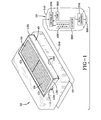
- An adjustable solar-power unit to energize a dispenser 10 is generally referred to by the numeral 20, as shown in Fig. 1 of the drawings.
- the adjustable solar-power unit 20, as shown in Fig. 1 maintains a support housing 30 that rotatably retains a holder 40 that includes one or more solar elements 50.
- solar element is defined as any solar panel, solar cell, photovoltaic device, or portion thereof that is capable of converting solar energy into electrical power.
- the solar elements 50 are electrically coupled to the dispenser 10 to provide operational power thereto.
- the rotatable holder 40 allows the one or more solar elements 50 to be positioned so that they are optimally oriented to capture the maximum amount of incoming ambient light.
- the adjustable solar-power unit 20 may be mounted at any desired location that is in the proximity of a light source 60, as shown in Fig.
- any other fixture 70 including but not limited to: automatic faucets; automatic toilets; dispensers of viscous material, such as soap, sanitizer, and lotion; towel dispensers; tablet dispensers; wipe dispensers; personal-hygiene object dispensers; automatic-flush toilet systems; automatic faucets; and automatic air-deodorant spray systems.
- the support housing 30 of the adjustable solar-panel unit 20 includes a receiving aperture 100 that is sized and dimensioned to receive the holder 40 therein.
- the support housing 30 also maintains a pair of opposed retainers 110 that receive and pivotably retain corresponding cylindrical pivots 120 that extend from each end 130 and 132 of the holder 40, thus allowing the holder 40 to be rotated to any desired position.
- the support housing 30 may be formed from any suitable material, such as plastic or metal.
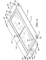
- the holder 40 is configured so that it can be manufactured as a substantially flat section, having an interior surface 150 and an exterior surface 152, that is folded in a manner to form the operative holder 40 that is able to pivot or rotate within the support housing 30.
- the holder 40 comprises a central section 202 that is surrounded by opposed lateral support sections 210 and 212 and opposed pivot sections 220 and 222, which maintain one of the pivots 120.
- the holder 40 may comprise a unitary section of material, such as plastic or aluminum.
- folding the lateral support sections 210,212 and the pivot sections 220,222 with respect to the central section 202 results in a plurality of foldable living hinges being formed at the interface between the central section 202 and each of the lateral support sections 210,212 and pivot sections 220,222.
- living hinges 230,232 are respectively formed at the interface between the central section 202 and the lateral support sections 210,212
- living hinges 240,242 are respectively formed at the interface between the central section 202 and the pivot sections 220,222.
- the living hinges 230,232,240,242 allow the holder 40 to be formed from a flat section of material, such as plastic, and then later configured as the finished operative holder 40, shown in Figs. 6 and 7 .
- the lateral support sections 210,212 and the pivot sections 220,222 fold about respective living hinges 230,232 and 240,242 so that they are oriented at a substantially right angle to that of the central section 202 once folded.
- the lateral support sections 210,212 may be configured to have an arcuate or curved profile to facilitate their rotating movement within the receiving aperture 100 of the support housing 30.
- the lateral support sections 210,212 include respective pairs of locking tabs 250 and 252 at each of their ends 254,256, while the pivot sections 220,222 include a pair of attachment apertures 260,262 at each of their ends 264,266.
- the attachment apertures 260,262 receive locking tabs 250,252, respectively, which co-act to retain the sections 210,212,220,222 at a substantially right angle to the central section 202.
- the lateral support sections 210,212 and the pivot sections 220,222 may be retained to one another via any other suitable means, including adhesive, rivets, screws, or the like.
- the solar elements 50 are attached to the exterior surface 152 of the central section 202 using any suitable means of fixation, such as adhesive for example.
- a power connector 280 Disposed upon the interior surface 150 of the central section 202 of the holder 40 is a power connector 280 that electrically couples the dispenser 10 to the solar elements 50 via a removable power line 300.
- the power line 300 may be removably attached to the power connector 280, it is also contemplated that the power line 300 may be directly coupled to the solar elements 50, thereby foregoing the need of the power connector 280.
- the power line 300 supplies power to the dispenser 10 to enable its operation of dispensing various material or items therefrom in a manner to be discussed.
- the dispenser 10 includes a housing 340, which may be comprised of any suitable material, such as plastic or metal for example.
- the housing 340 carries a controller 350, which comprises the necessary hardware and/or software needed to carry out the functions to be discussed.
- Coupled to the controller 350 is a pump 360 that is in operative communication with a replaceable refill container 370, which maintains any suitable material or item to be dispensed, such as soap.
- An actuator 380 coupled to the controller 150 initiates a dispensing cycle of an amount of material from a nozzle 390.
- the actuator 380 may comprise a manually-actuated button, lever, or other device that when physically engaged, prompts the controller 350 to actuate the pump 360, so as to dispense material from the refill container 370.
- the dispenser 100 may be configured to enable touch-free operation, such that the actuator 380 is configured as a proximity sensor, such as an IR (infrared) sensor, whereupon the presence of the user's hand initiates the dispensement of material from the refill container 110.
- IR infrared
- the adjustable solar-power unit 20 may be placed in a region that receives solar energy but is remotely located from the dispenser 10, which is beneficial, as it allows power to be supplied to one or more dispensers 10 that may not be placed in regions with adequate ambient light to enable the operation of the solar elements 50.
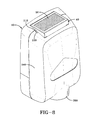
- the holder 40 of the adjustable solar-power unit 20 may be made integral with the housing 340 that maintains the components of the dispenser 10, such as a manually-operated dispenser or a touch-free dispenser, as shown in Fig. 8 .
- the dispenser 10 is mounted in a region having a suitable amount of ambient light that allows the solar elements 50 to generate sufficient power therefrom to operate the dispenser 10.
- the holder 40 may be made with any other fixture, as previously discussed, where such a configuration is desirable.
- the dispenser 10 may be configured so that it is directly powered by the power generated by the solar panels 50.
- the dispenser 10 may include a rechargeable power source 400, such as a rechargeable battery or capacitor (not shown), which is recharged by the power supplied by the solar panels 50, thus allowing uninterrupted operation of the dispenser 10 when ambient lighting is available or not available.
- an adjustable solar-power unit provides an adjustable holder that can be positioned to allow the solar elements carried thereby to be positioned to enhance that amount of electrical power generated therefrom to power a dispenser.
- the adjustable solar-power unit may be located remotely from the dispenser.
- the adjustable solar-power unit may form a housing in which the components of the dispenser are maintained.
- the holder may be formed as a plurality of flat sections that are rotated via living hinges to form the holder.
Landscapes
- Engineering & Computer Science (AREA)
- Health & Medical Sciences (AREA)
- Public Health (AREA)
- Mechanical Engineering (AREA)
- Sustainable Energy (AREA)
- Thermal Sciences (AREA)
- Chemical & Material Sciences (AREA)
- Combustion & Propulsion (AREA)
- Physics & Mathematics (AREA)
- General Engineering & Computer Science (AREA)
- Sustainable Development (AREA)
- Life Sciences & Earth Sciences (AREA)
- Photovoltaic Devices (AREA)
- Devices For Dispensing Beverages (AREA)
- Containers And Packaging Bodies Having A Special Means To Remove Contents (AREA)
- Charge And Discharge Circuits For Batteries Or The Like (AREA)
Abstract
Description
- Generally, the present invention relates to dispensers for dispensing material.
In particular, the present invention is directed to solar-powered dispensers. More particularly, the present invention is directed to an adjustable solar-power unit for a dispenser in which the angle of the solar elements may be adjusted to enhance the capture of solar energy. - Touch-free and other automatic dispensers require electrical power in order to dispense material from a refill container. For example, in the case of touch-free soap dispensers, soap is automatically dispensed upon the detection of a user's hand via an IR (infrared) sensor. While some dispensers may utilize a wired power source, such as a wall outlet, this restricts the location at which the dispenser may be mounted to those areas where such outlets are available. To overcome this, many touch-free or automatic dispensers utilize a portable power source, such as a battery, thereby allowing the dispenser to be mounted in any desired location.
- Batteries, however, require frequent replacement, which is costly, and as such, dispensers that utilize solar power would be beneficial. Furthermore, there is a need for an adjustable solar-power unit that is configured to be integral with a dispenser. Additionally, there is a need for an adjustable solar-power unit that may be mounted in a remote location separate from a dispenser. Still yet, there is a need for an adjustable solar-power unit that is manufactured as a flat section and then folded via living hinges, so as to reduce manufacturing costs. In addition, there is a need for an adjustable solar-power unit having a holder to adjust the position of a solar element with respect to ambient light.
- An adjustable solar-power unit to power a dispenser comprising a support housing having a pair of opposed retainers; a holder maintaining a pair of opposed pivots extending therefrom that are rotatably retained by said retainers; and at least one solar element carried by said holder and adapted to be electrically coupled to the dispenser, wherein said holder is rotatably moved to adjust the angle of said at least one solar element with respect to incoming ambient light received thereby, in order to generate power for the dispenser.
- A dispenser for dispensing material comprising a housing maintaining a pair of opposed retainers; a holder having a pair of opposed pivots extending therefrom that are rotatably retained by said retainers; at least one solar element carried by said holder; a dispenser controller electrically coupled to said solar element; a pump coupled to said dispenser controller, said pump adapted to dispense said material from said dispenser; and an actuator coupled to said dispenser controller, wherein said solar element is rotatably adjusted to position said solar element to adjust the amount of ambient light received thereby to power said dispenser controller, such that said pump dispenses material from the dispenser when said actuator is engaged.
- These and other features and advantages of the present invention will become better understood with regard to the following description, appended claims, and accompanying drawings wherein:
-
Fig. 1 is a perspective view of a dispenser remotely coupled to a support housing provided by an adjustable solar-power unit in accordance with the concepts of the present invention; -
Fig. 2 is a perspective view of an adjustable solar-power unit remotely coupled to a dispenser and to a fixture in accordance with the concepts of the present invention; -
Fig. 3 is a top plan view of the adjustable solar-power unit in accordance with the concepts of the present invention; -
Fig. 4 is a perspective view of the exterior surface of a holder maintained by the adjustable solar-power unit in accordance with the concepts of the present invention; -
Fig. 5 is a perspective view of the interior surface of the holder carried by the support housing in accordance with the concepts of the present invention; -
Fig. 6 is a top perspective view of the assembled holder in accordance with the concepts of the present invention; -
Fig. 7 is a bottom perspective view of the assembled holder in accordance with the concepts of the present invention; and -
Fig. 8 is a perspective view of the holder when made integral with a dispenser housing in accordance with the concepts of the present invention. - Solar-powered dispensers are configured with various solar panels or solar cells that are affixed to the dispenser housing to capture and convert the solar energy from the ambient light that is incident thereon into electrical power. The converted electrical power is then used to directly power the dispenser or to charge a rechargeable battery or capacitor maintained within the dispenser housing. However, the angle in which light is incident upon the surface of the solar panel or solar cells directly affects the amount of electrical power that is converted by the solar panels.
- For example, in certain scenarios, dispensers may be configured with various solar panels and solar cells positioned in a predetermined and standard position in relation to the ambient light source and may provide sufficient power for full or supplemental power to the dispenser. However, due to many factors, including but not limited to the reduced size and surface area provided for placement of solar panels on many dispensers, the often low levels of ambient light from sunlight and/or artificial light within a room, and the placement of dispensers on or near walls or near other shadow-causing objects, the placement of the solar panels at a predetermined angle in relation to the ambient light source may not be sufficient to generate adequate energy. That is, due to the various locations in which a dispenser may be mounted, the angle in which ambient light is incident upon the solar panel or solar cells is often not optimal for the efficient generation of electrical power. As such, it is foreseen that many solar-powered dispensers generate an insufficient amount of electrical power in which to adequately power the dispenser, thus leading to unsatisfactory dispenser performance. Thus, therefore there is a need to provide a solar unit for a dispenser, whereby a rotating solar unit allows for the adjustment of the angle between the solar panel or solar cell and the light incident thereon that is provided by an ambient light source within the area in which the dispenser is placed.
- An adjustable solar-power unit to energize a
dispenser 10 is generally referred to by thenumeral 20, as shown inFig. 1 of the drawings. The adjustable solar-power unit 20, as shown inFig. 1 , maintains asupport housing 30 that rotatably retains aholder 40 that includes one or moresolar elements 50. For the purposes of the following discussion, the term "solar element" is defined as any solar panel, solar cell, photovoltaic device, or portion thereof that is capable of converting solar energy into electrical power. Thesolar elements 50 are electrically coupled to thedispenser 10 to provide operational power thereto. Therotatable holder 40 allows the one or moresolar elements 50 to be positioned so that they are optimally oriented to capture the maximum amount of incoming ambient light. For example, by rotating theholder 40 to a position whereby thesolar elements 50 are oriented perpendicular to incident ambient light, thesolar elements 50 are allowed to operate at their highest level of power output, which allows thedispenser 10 that is coupled thereto to be optimally powered. As such, the adjustable solar-power unit 20 may be mounted at any desired location that is in the proximity of alight source 60, as shown inFig. 2 , to thereby remotely power thedispenser 10, as well as anyother fixture 70, including but not limited to: automatic faucets; automatic toilets; dispensers of viscous material, such as soap, sanitizer, and lotion; towel dispensers; tablet dispensers; wipe dispensers; personal-hygiene object dispensers; automatic-flush toilet systems; automatic faucets; and automatic air-deodorant spray systems. - Continuing to
Fig. 3 , the support housing 30 of the adjustable solar-panel unit 20 includes a receivingaperture 100 that is sized and dimensioned to receive theholder 40 therein. In addition, thesupport housing 30 also maintains a pair ofopposed retainers 110 that receive and pivotably retain correspondingcylindrical pivots 120 that extend from eachend holder 40, thus allowing theholder 40 to be rotated to any desired position. It should be appreciated that thesupport housing 30 may be formed from any suitable material, such as plastic or metal. - As shown in
Figs. 4-5 , theholder 40 is configured so that it can be manufactured as a substantially flat section, having aninterior surface 150 and anexterior surface 152, that is folded in a manner to form theoperative holder 40 that is able to pivot or rotate within thesupport housing 30. As such, theholder 40 comprises acentral section 202 that is surrounded by opposedlateral support sections pivot sections pivots 120. In one aspect, theholder 40 may comprise a unitary section of material, such as plastic or aluminum. Thus, folding the lateral support sections 210,212 and the pivot sections 220,222 with respect to thecentral section 202 results in a plurality of foldable living hinges being formed at the interface between thecentral section 202 and each of the lateral support sections 210,212 and pivot sections 220,222. Specifically, living hinges 230,232 are respectively formed at the interface between thecentral section 202 and the lateral support sections 210,212, while living hinges 240,242 are respectively formed at the interface between thecentral section 202 and the pivot sections 220,222. The living hinges 230,232,240,242 allow theholder 40 to be formed from a flat section of material, such as plastic, and then later configured as the finishedoperative holder 40, shown inFigs. 6 and7 . As such, the lateral support sections 210,212 and the pivot sections 220,222 fold about respective living hinges 230,232 and 240,242 so that they are oriented at a substantially right angle to that of thecentral section 202 once folded. It should be appreciated that the lateral support sections 210,212 may be configured to have an arcuate or curved profile to facilitate their rotating movement within the receivingaperture 100 of thesupport housing 30. - In order to maintain the orientation of the lateral support sections 210,212 and the pivot sections 220,222 with respect to the
central section 202 when folded, the lateral support sections 210,212 include respective pairs oflocking tabs holder 40 are folded so as to be at a substantially right angle to thecentral section 202, the attachment apertures 260,262 receive locking tabs 250,252, respectively, which co-act to retain the sections 210,212,220,222 at a substantially right angle to thecentral section 202. Alternatively, the lateral support sections 210,212 and the pivot sections 220,222 may be retained to one another via any other suitable means, including adhesive, rivets, screws, or the like. - Continuing, the
solar elements 50 are attached to theexterior surface 152 of thecentral section 202 using any suitable means of fixation, such as adhesive for example. Disposed upon theinterior surface 150 of thecentral section 202 of theholder 40 is apower connector 280 that electrically couples thedispenser 10 to thesolar elements 50 via aremovable power line 300. While thepower line 300 may be removably attached to thepower connector 280, it is also contemplated that thepower line 300 may be directly coupled to thesolar elements 50, thereby foregoing the need of thepower connector 280. As such, thepower line 300 supplies power to thedispenser 10 to enable its operation of dispensing various material or items therefrom in a manner to be discussed. - Returning to
Fig. 1 , thedispenser 10 includes ahousing 340, which may be comprised of any suitable material, such as plastic or metal for example. Thehousing 340 carries acontroller 350, which comprises the necessary hardware and/or software needed to carry out the functions to be discussed. Coupled to thecontroller 350 is apump 360 that is in operative communication with areplaceable refill container 370, which maintains any suitable material or item to be dispensed, such as soap. Anactuator 380 coupled to thecontroller 150 initiates a dispensing cycle of an amount of material from anozzle 390. Theactuator 380 may comprise a manually-actuated button, lever, or other device that when physically engaged, prompts thecontroller 350 to actuate thepump 360, so as to dispense material from therefill container 370. Alternatively, thedispenser 100 may be configured to enable touch-free operation, such that theactuator 380 is configured as a proximity sensor, such as an IR (infrared) sensor, whereupon the presence of the user's hand initiates the dispensement of material from therefill container 110. Thus, to energize thecontroller 350 and the other components of thedispenser 10 to enable its operation, power generated by thesolar elements 50 is delivered to thecontroller 350 via thepower line 300, where the power is formatted in a manner compatible for the operation of thedispenser 10. - Thus, the adjustable solar-
power unit 20 may be placed in a region that receives solar energy but is remotely located from thedispenser 10, which is beneficial, as it allows power to be supplied to one ormore dispensers 10 that may not be placed in regions with adequate ambient light to enable the operation of thesolar elements 50. - In another embodiment, the
holder 40 of the adjustable solar-power unit 20 may be made integral with thehousing 340 that maintains the components of thedispenser 10, such as a manually-operated dispenser or a touch-free dispenser, as shown inFig. 8 . Such a configuration is beneficial when thedispenser 10 is mounted in a region having a suitable amount of ambient light that allows thesolar elements 50 to generate sufficient power therefrom to operate thedispenser 10. Furthermore, theholder 40 may be made with any other fixture, as previously discussed, where such a configuration is desirable. - It should be appreciated that the
dispenser 10 may be configured so that it is directly powered by the power generated by thesolar panels 50. Or thedispenser 10 may include arechargeable power source 400, such as a rechargeable battery or capacitor (not shown), which is recharged by the power supplied by thesolar panels 50, thus allowing uninterrupted operation of thedispenser 10 when ambient lighting is available or not available. - It will, therefore, be appreciated that one advantage of one or more embodiments of the present invention is that an adjustable solar-power unit provides an adjustable holder that can be positioned to allow the solar elements carried thereby to be positioned to enhance that amount of electrical power generated therefrom to power a dispenser. Another advantage of the present invention is that the adjustable solar-power unit may be located remotely from the dispenser. Yet another advantage of the present invention is that the adjustable solar-power unit may form a housing in which the components of the dispenser are maintained. Still another advantage of the present invention is that the holder may be formed as a plurality of flat sections that are rotated via living hinges to form the holder.
- Although the present invention has been described in considerable detail with reference to certain embodiments, other embodiments are possible. Therefore, the spirit and scope of the appended claims should not be limited to the description of the embodiments contained herein.
Claims (15)
- An adjustable solar-power unit to power a dispenser comprising:a support housing having a pair of opposed retainers;a holder maintaining a pair of opposed pivots extending therefrom that are rotatably retained by said retainers; andat least one solar element carried by said holder and adapted to be electrically coupled to the dispenser;wherein said holder is rotatably moved to adjust the angle of said at least one solar element with respect to incoming ambient light received thereby, in order to generate power for the dispenser.
- The adjustable solar-power unit of claim 1, further comprising:a receiving aperture disposed within said support housing to receive said holder therewithin.
- The adjustable solar-power unit of claim 1, wherein said holder comprises a central section carrying said at least one solar element, said holder including a pair of pivot sections, one of which is attached at each end of said central section,
wherein each said pivot section maintains one of said pivots. - The adjustable solar-power unit of claim 3, wherein said holder further comprises a pair of lateral support sections attached to said central section between said pivot sections.
- The adjustable solar-power unit of claim 4, wherein said pivot sections and said lateral support sections are attached to said central section via respective living hinges.
- The adjustable solar-power unit of claim 4, wherein said lateral support sections each maintain at least one locking tab at each end, and said pivot sections maintain at least one attachment aperture at each end to receive and retain said locking tabs therein.
- The adjustable solar-power unit of claim 1, wherein at least one solar element is electrically coupled to a power connector maintained by said holder, said power connector adapted to be removably coupled to the dispenser.
- A dispenser for dispensing material comprising:a housing maintaining a pair of opposed retainers;a holder having a pair of opposed pivots extending therefrom that are rotatably retained by said retainers;at least one solar element carried by said holder;a dispenser controller electrically coupled to said solar element;a pump coupled to said dispenser controller, said pump adapted to dispense said material from said dispenser; andan actuator coupled to said dispenser controller;wherein said solar element is rotatably adjusted to position said solar element to adjust the amount of ambient light received thereby to power said dispenser controller, such that said pump dispenses material from the dispenser when said actuator is engaged.
- The dispenser of claim 8, wherein said holder comprises a central section carrying said at least one solar element, said holder including a pair of pivot sections, one of which is attached at each end of said central section, wherein each said pivot section maintains one of said pivots.
- The dispenser of claim 9, wherein said holder further comprises a pair of lateral support sections attached to said central section between said pivot sections.
- The dispenser of claim 10, wherein said pivot sections and said lateral support sections are attached to said central section via respective living hinges.
- The dispenser of claim 10, wherein said lateral support sections each maintain at least one locking tab at each end, and said pivot sections maintain at least one attachment aperture at each end to receive and retain said locking tabs therein.
- The dispenser of claim 9, wherein at least one solar element is electrically coupled to a power connector maintained by said holder, said power connector adapted to be removably coupled to said dispenser controller.
- The dispenser of claim 8, further comprising a rechargeable power source coupled to said dispenser controller, wherein said power generated by said at least one solar element charges said rechargeable power source.
- The dispenser of claim 8, further comprising:a receiving aperture disposed within said housing to receive said holder therewithin.
Applications Claiming Priority (1)
| Application Number | Priority Date | Filing Date | Title |
|---|---|---|---|
| US12/416,416 US9241600B2 (en) | 2009-04-01 | 2009-04-01 | Adjustable solar-power unit for a dispenser |
Publications (3)
| Publication Number | Publication Date |
|---|---|
| EP2236066A2 true EP2236066A2 (en) | 2010-10-06 |
| EP2236066A3 EP2236066A3 (en) | 2013-08-21 |
| EP2236066B1 EP2236066B1 (en) | 2016-10-19 |
Family
ID=42289598
Family Applications (1)
| Application Number | Title | Priority Date | Filing Date |
|---|---|---|---|
| EP10158441.5A Not-in-force EP2236066B1 (en) | 2009-04-01 | 2010-03-30 | Dispenser with and adjustable solar-power unit |
Country Status (10)
| Country | Link |
|---|---|
| US (1) | US9241600B2 (en) |
| EP (1) | EP2236066B1 (en) |
| JP (2) | JP5864081B2 (en) |
| KR (1) | KR20100109862A (en) |
| CN (1) | CN101857113A (en) |
| AU (1) | AU2010201259B2 (en) |
| BR (1) | BRPI1000867A2 (en) |
| CA (1) | CA2698015C (en) |
| MY (1) | MY152479A (en) |
| TW (1) | TWI479110B (en) |
Cited By (3)
| Publication number | Priority date | Publication date | Assignee | Title |
|---|---|---|---|---|
| EP2939579A1 (en) * | 2014-05-01 | 2015-11-04 | OP-Hygiene IP GmbH | Solar powered dispenser system |
| US10040660B1 (en) | 2017-07-17 | 2018-08-07 | Gpcp Ip Holdings Llc | Power device for a product dispenser |
| US11788518B1 (en) * | 2023-05-26 | 2023-10-17 | David H. Henry | Low-profile solar-powered flood control device |
Families Citing this family (7)
| Publication number | Priority date | Publication date | Assignee | Title |
|---|---|---|---|---|
| US9241600B2 (en) * | 2009-04-01 | 2016-01-26 | Gojo Industries, Inc. | Adjustable solar-power unit for a dispenser |
| WO2011130158A1 (en) * | 2010-04-16 | 2011-10-20 | Gojo Industries, Inc. | Taggant keying system for dispensing systems |
| US8816536B2 (en) | 2010-11-24 | 2014-08-26 | Georgia-Pacific Consumer Products Lp | Apparatus and method for wirelessly powered dispensing |
| KR102154812B1 (en) * | 2014-09-29 | 2020-09-11 | 박진우 | Bag with solar charging and Advertise |
| US9701508B2 (en) | 2015-02-06 | 2017-07-11 | Georgia-Pacific Consumer Products Lp | Hybrid dispenser systems |
| US12016960B2 (en) * | 2020-09-02 | 2024-06-25 | Sloan Valve Company | Ultraviolet hand sanitizer |
| US11638770B2 (en) * | 2020-12-09 | 2023-05-02 | Boguslaw Kolakowski | Ultraviolet sanitizing apparatus |
Family Cites Families (24)
| Publication number | Priority date | Publication date | Assignee | Title |
|---|---|---|---|---|
| US2400776A (en) * | 1945-01-01 | 1946-05-21 | Package Service Company | Tape dispenser |
| JPS5554030Y2 (en) | 1976-05-28 | 1980-12-15 | ||
| US4773944A (en) * | 1987-09-08 | 1988-09-27 | Energy Conversion Devices, Inc. | Large area, low voltage, high current photovoltaic modules and method of fabricating same |
| US5772291A (en) | 1996-02-16 | 1998-06-30 | Mosinee Paper Corporation | Hands-free paper towel dispensers |
| US6695246B1 (en) | 1996-02-16 | 2004-02-24 | Bay West Paper Corporation | Microprocessor controlled hands-free paper towel dispenser |
| US6293486B1 (en) | 1998-02-16 | 2001-09-25 | Mosinee Paper Corporation | Hands-free paper towel dispensers |
| US6201181B1 (en) * | 1998-12-08 | 2001-03-13 | Ase Americas, Inc. | Portable solar module cart |
| US6209752B1 (en) * | 1999-03-10 | 2001-04-03 | Kimberly-Clark Worldwide, Inc. | Automatic soap dispenser |
| JP3062864U (en) * | 1999-03-29 | 1999-10-15 | ジャスト技研株式会社 | Ventilation fan for exhausting indoor air using solar cells |
| US6263674B1 (en) | 2000-09-15 | 2001-07-24 | Stephen Fileman | Solar-powered, mobile vending apparatus |
| CN1531404A (en) | 2000-12-19 | 2004-09-22 | - | Self-contained viscous liquid dispenser |
| DE10103890A1 (en) | 2001-01-30 | 2002-08-08 | Hartmut J Schneider | Dispenser for a hand-cleaning product comprises a sensor powered by a solar cell and opening when approached by a hand a valve connected in series with the liquid container and dispensing cleaning product |
| US6870087B1 (en) | 2001-09-14 | 2005-03-22 | Patrick Gallagher | Assembly method and apparatus for photovoltaic module |
| WO2004036124A1 (en) | 2002-10-17 | 2004-04-29 | Michael Terrence Patterson | Solar tracking apparatus |
| JP2005249268A (en) * | 2004-03-03 | 2005-09-15 | Sanyo Electric Co Ltd | Power generation device of separator type air conditioner |
| US7182222B2 (en) | 2004-05-29 | 2007-02-27 | Prabucki Robert W | Solar panel and water dispenser |
| CA2477584C (en) | 2004-08-12 | 2011-07-26 | Hygiene-Technik Inc. | Disposable dispenser |
| CA2505812C (en) * | 2004-08-12 | 2013-04-09 | Gotohti.Com Inc. | Cantilevered spring |
| US20060090789A1 (en) * | 2004-10-29 | 2006-05-04 | Thompson Daniel S | Floating support structure for a solar panel array |
| WO2007084517A2 (en) * | 2006-01-17 | 2007-07-26 | Soliant Energy, Inc. | Concentrating solar panel and related systems and methods |
| WO2008051973A1 (en) | 2006-10-24 | 2008-05-02 | Bradley Fixtures Corporation | Capacitive sensing for washroom fixture |
| JP2008113210A (en) * | 2006-10-30 | 2008-05-15 | Aiphone Co Ltd | Mount for interphone slave machine |
| WO2008124642A2 (en) | 2007-04-04 | 2008-10-16 | Thompson Technology Industries, Inc. | Adjustable tilt slar panel support system |
| US9241600B2 (en) * | 2009-04-01 | 2016-01-26 | Gojo Industries, Inc. | Adjustable solar-power unit for a dispenser |
-
2009
- 2009-04-01 US US12/416,416 patent/US9241600B2/en active Active
-
2010
- 2010-03-30 AU AU2010201259A patent/AU2010201259B2/en not_active Ceased
- 2010-03-30 CA CA2698015A patent/CA2698015C/en active Active
- 2010-03-30 EP EP10158441.5A patent/EP2236066B1/en not_active Not-in-force
- 2010-03-31 BR BRPI1000867-5A patent/BRPI1000867A2/en not_active IP Right Cessation
- 2010-03-31 JP JP2010080626A patent/JP5864081B2/en not_active Expired - Fee Related
- 2010-03-31 MY MYPI2010001445 patent/MY152479A/en unknown
- 2010-03-31 TW TW099109931A patent/TWI479110B/en active
- 2010-03-31 KR KR1020100028974A patent/KR20100109862A/en not_active Ceased
- 2010-04-01 CN CN201010141611A patent/CN101857113A/en active Pending
-
2015
- 2015-07-31 JP JP2015152240A patent/JP2016021860A/en not_active Ceased
Non-Patent Citations (1)
| Title |
|---|
| None |
Cited By (4)
| Publication number | Priority date | Publication date | Assignee | Title |
|---|---|---|---|---|
| EP2939579A1 (en) * | 2014-05-01 | 2015-11-04 | OP-Hygiene IP GmbH | Solar powered dispenser system |
| US9756989B2 (en) | 2014-05-01 | 2017-09-12 | Op-Hygiene Ip Gmbh | Solar powered dispenser system |
| US10040660B1 (en) | 2017-07-17 | 2018-08-07 | Gpcp Ip Holdings Llc | Power device for a product dispenser |
| US11788518B1 (en) * | 2023-05-26 | 2023-10-17 | David H. Henry | Low-profile solar-powered flood control device |
Also Published As
| Publication number | Publication date |
|---|---|
| JP2016021860A (en) | 2016-02-04 |
| TWI479110B (en) | 2015-04-01 |
| JP5864081B2 (en) | 2016-02-17 |
| US20100252569A1 (en) | 2010-10-07 |
| EP2236066B1 (en) | 2016-10-19 |
| CA2698015A1 (en) | 2010-10-01 |
| JP2010245529A (en) | 2010-10-28 |
| MY152479A (en) | 2014-10-15 |
| CA2698015C (en) | 2018-08-21 |
| TW201100733A (en) | 2011-01-01 |
| AU2010201259B2 (en) | 2012-06-28 |
| KR20100109862A (en) | 2010-10-11 |
| CN101857113A (en) | 2010-10-13 |
| EP2236066A3 (en) | 2013-08-21 |
| BRPI1000867A2 (en) | 2011-03-22 |
| US9241600B2 (en) | 2016-01-26 |
| AU2010201259A1 (en) | 2010-10-21 |
Similar Documents
| Publication | Publication Date | Title |
|---|---|---|
| AU2010201259B2 (en) | Adjustable solar-power unit for a dispenser | |
| CA2850835C (en) | Solar powered dispenser system | |
| US6209752B1 (en) | Automatic soap dispenser | |
| US8353427B2 (en) | Automatic dispenser for hand-sanitizer lotion | |
| US20100237096A1 (en) | Wirelessly-powered dispenser system | |
| US7952233B2 (en) | Lavatory system | |
| US20040055627A1 (en) | Umbrella and kit therefor | |
| MX2008015772A (en) | Power supply systems for dispensers and methods of powering dispensers. | |
| CN104930360A (en) | Lighting device and manufacturing method thereof | |
| US11290052B2 (en) | Solar ultra-light operated battery and the method thereof | |
| JP2009016785A (en) | Solar photovoltaic portable generation unit | |
| CN105555323A (en) | Kit that converts a battery-powered automatic aroma sprayer into a solar-powered kit | |
| US20190161952A1 (en) | Portable bidet module | |
| US20160377069A1 (en) | Liquid pumping device with solar panel | |
| US20050213326A1 (en) | Modular lighting device | |
| HK1143725A (en) | Adjustable solar-power unit for a dispenser | |
| EP3210499B1 (en) | Structure for a sunbed, deckchair, telescopic tripod or tanning and refreshing platform | |
| US10103567B2 (en) | Photovoltaic cell accessory for a battery powered device | |
| EP3064115A1 (en) | A kit for converting a battery-powered automatic towel dispenser to solar power | |
| CN118490089A (en) | Portable multifunctional tissue box | |
| HK1143050A (en) | Wirelessly-powered dispenser system | |
| JP2003017734A (en) | Solar parasol |
Legal Events
| Date | Code | Title | Description |
|---|---|---|---|
| PUAI | Public reference made under article 153(3) epc to a published international application that has entered the european phase |
Free format text: ORIGINAL CODE: 0009012 |
|
| AK | Designated contracting states |
Kind code of ref document: A2 Designated state(s): AT BE BG CH CY CZ DE DK EE ES FI FR GB GR HR HU IE IS IT LI LT LU LV MC MK MT NL NO PL PT RO SE SI SK SM TR |
|
| AX | Request for extension of the european patent |
Extension state: AL BA ME RS |
|
| REG | Reference to a national code |
Ref country code: HK Ref legal event code: DE Ref document number: 1143725 Country of ref document: HK |
|
| PUAL | Search report despatched |
Free format text: ORIGINAL CODE: 0009013 |
|
| AK | Designated contracting states |
Kind code of ref document: A3 Designated state(s): AT BE BG CH CY CZ DE DK EE ES FI FR GB GR HR HU IE IS IT LI LT LU LV MC MK MT NL NO PL PT RO SE SI SK SM TR |
|
| AX | Request for extension of the european patent |
Extension state: AL BA ME RS |
|
| RIC1 | Information provided on ipc code assigned before grant |
Ipc: A47K 5/12 20060101AFI20130717BHEP Ipc: F24J 2/54 20060101ALI20130717BHEP |
|
| 17P | Request for examination filed |
Effective date: 20140214 |
|
| RBV | Designated contracting states (corrected) |
Designated state(s): AT BE BG CH CY CZ DE DK EE ES FI FR GB GR HR HU IE IS IT LI LT LU LV MC MK MT NL NO PL PT RO SE SI SK SM TR |
|
| GRAP | Despatch of communication of intention to grant a patent |
Free format text: ORIGINAL CODE: EPIDOSNIGR1 |
|
| INTG | Intention to grant announced |
Effective date: 20160503 |
|
| GRAS | Grant fee paid |
Free format text: ORIGINAL CODE: EPIDOSNIGR3 |
|
| GRAA | (expected) grant |
Free format text: ORIGINAL CODE: 0009210 |
|
| AK | Designated contracting states |
Kind code of ref document: B1 Designated state(s): AT BE BG CH CY CZ DE DK EE ES FI FR GB GR HR HU IE IS IT LI LT LU LV MC MK MT NL NO PL PT RO SE SI SK SM TR |
|
| REG | Reference to a national code |
Ref country code: GB Ref legal event code: FG4D |
|
| REG | Reference to a national code |
Ref country code: HK Ref legal event code: WD Ref document number: 1143725 Country of ref document: HK |
|
| REG | Reference to a national code |
Ref country code: CH Ref legal event code: EP |
|
| REG | Reference to a national code |
Ref country code: AT Ref legal event code: REF Ref document number: 837589 Country of ref document: AT Kind code of ref document: T Effective date: 20161115 |
|
| REG | Reference to a national code |
Ref country code: IE Ref legal event code: FG4D |
|
| REG | Reference to a national code |
Ref country code: DE Ref legal event code: R096 Ref document number: 602010037261 Country of ref document: DE |
|
| REG | Reference to a national code |
Ref country code: NL Ref legal event code: MP Effective date: 20161019 |
|
| REG | Reference to a national code |
Ref country code: LT Ref legal event code: MG4D |
|
| PG25 | Lapsed in a contracting state [announced via postgrant information from national office to epo] |
Ref country code: LV Free format text: LAPSE BECAUSE OF FAILURE TO SUBMIT A TRANSLATION OF THE DESCRIPTION OR TO PAY THE FEE WITHIN THE PRESCRIBED TIME-LIMIT Effective date: 20161019 |
|
| REG | Reference to a national code |
Ref country code: AT Ref legal event code: MK05 Ref document number: 837589 Country of ref document: AT Kind code of ref document: T Effective date: 20161019 |
|
| REG | Reference to a national code |
Ref country code: FR Ref legal event code: PLFP Year of fee payment: 8 |
|
| PG25 | Lapsed in a contracting state [announced via postgrant information from national office to epo] |
Ref country code: NO Free format text: LAPSE BECAUSE OF FAILURE TO SUBMIT A TRANSLATION OF THE DESCRIPTION OR TO PAY THE FEE WITHIN THE PRESCRIBED TIME-LIMIT Effective date: 20170119 Ref country code: GR Free format text: LAPSE BECAUSE OF FAILURE TO SUBMIT A TRANSLATION OF THE DESCRIPTION OR TO PAY THE FEE WITHIN THE PRESCRIBED TIME-LIMIT Effective date: 20170120 Ref country code: SE Free format text: LAPSE BECAUSE OF FAILURE TO SUBMIT A TRANSLATION OF THE DESCRIPTION OR TO PAY THE FEE WITHIN THE PRESCRIBED TIME-LIMIT Effective date: 20161019 Ref country code: LT Free format text: LAPSE BECAUSE OF FAILURE TO SUBMIT A TRANSLATION OF THE DESCRIPTION OR TO PAY THE FEE WITHIN THE PRESCRIBED TIME-LIMIT Effective date: 20161019 |
|
| PG25 | Lapsed in a contracting state [announced via postgrant information from national office to epo] |
Ref country code: PL Free format text: LAPSE BECAUSE OF FAILURE TO SUBMIT A TRANSLATION OF THE DESCRIPTION OR TO PAY THE FEE WITHIN THE PRESCRIBED TIME-LIMIT Effective date: 20161019 Ref country code: BE Free format text: LAPSE BECAUSE OF FAILURE TO SUBMIT A TRANSLATION OF THE DESCRIPTION OR TO PAY THE FEE WITHIN THE PRESCRIBED TIME-LIMIT Effective date: 20161019 Ref country code: ES Free format text: LAPSE BECAUSE OF FAILURE TO SUBMIT A TRANSLATION OF THE DESCRIPTION OR TO PAY THE FEE WITHIN THE PRESCRIBED TIME-LIMIT Effective date: 20161019 Ref country code: AT Free format text: LAPSE BECAUSE OF FAILURE TO SUBMIT A TRANSLATION OF THE DESCRIPTION OR TO PAY THE FEE WITHIN THE PRESCRIBED TIME-LIMIT Effective date: 20161019 Ref country code: PT Free format text: LAPSE BECAUSE OF FAILURE TO SUBMIT A TRANSLATION OF THE DESCRIPTION OR TO PAY THE FEE WITHIN THE PRESCRIBED TIME-LIMIT Effective date: 20170220 Ref country code: FI Free format text: LAPSE BECAUSE OF FAILURE TO SUBMIT A TRANSLATION OF THE DESCRIPTION OR TO PAY THE FEE WITHIN THE PRESCRIBED TIME-LIMIT Effective date: 20161019 Ref country code: IS Free format text: LAPSE BECAUSE OF FAILURE TO SUBMIT A TRANSLATION OF THE DESCRIPTION OR TO PAY THE FEE WITHIN THE PRESCRIBED TIME-LIMIT Effective date: 20170219 Ref country code: HR Free format text: LAPSE BECAUSE OF FAILURE TO SUBMIT A TRANSLATION OF THE DESCRIPTION OR TO PAY THE FEE WITHIN THE PRESCRIBED TIME-LIMIT Effective date: 20161019 Ref country code: NL Free format text: LAPSE BECAUSE OF FAILURE TO SUBMIT A TRANSLATION OF THE DESCRIPTION OR TO PAY THE FEE WITHIN THE PRESCRIBED TIME-LIMIT Effective date: 20161019 |
|
| REG | Reference to a national code |
Ref country code: DE Ref legal event code: R097 Ref document number: 602010037261 Country of ref document: DE |
|
| PG25 | Lapsed in a contracting state [announced via postgrant information from national office to epo] |
Ref country code: RO Free format text: LAPSE BECAUSE OF FAILURE TO SUBMIT A TRANSLATION OF THE DESCRIPTION OR TO PAY THE FEE WITHIN THE PRESCRIBED TIME-LIMIT Effective date: 20161019 Ref country code: SK Free format text: LAPSE BECAUSE OF FAILURE TO SUBMIT A TRANSLATION OF THE DESCRIPTION OR TO PAY THE FEE WITHIN THE PRESCRIBED TIME-LIMIT Effective date: 20161019 Ref country code: CZ Free format text: LAPSE BECAUSE OF FAILURE TO SUBMIT A TRANSLATION OF THE DESCRIPTION OR TO PAY THE FEE WITHIN THE PRESCRIBED TIME-LIMIT Effective date: 20161019 Ref country code: EE Free format text: LAPSE BECAUSE OF FAILURE TO SUBMIT A TRANSLATION OF THE DESCRIPTION OR TO PAY THE FEE WITHIN THE PRESCRIBED TIME-LIMIT Effective date: 20161019 Ref country code: DK Free format text: LAPSE BECAUSE OF FAILURE TO SUBMIT A TRANSLATION OF THE DESCRIPTION OR TO PAY THE FEE WITHIN THE PRESCRIBED TIME-LIMIT Effective date: 20161019 |
|
| PLBE | No opposition filed within time limit |
Free format text: ORIGINAL CODE: 0009261 |
|
| STAA | Information on the status of an ep patent application or granted ep patent |
Free format text: STATUS: NO OPPOSITION FILED WITHIN TIME LIMIT |
|
| PG25 | Lapsed in a contracting state [announced via postgrant information from national office to epo] |
Ref country code: SM Free format text: LAPSE BECAUSE OF FAILURE TO SUBMIT A TRANSLATION OF THE DESCRIPTION OR TO PAY THE FEE WITHIN THE PRESCRIBED TIME-LIMIT Effective date: 20161019 Ref country code: IT Free format text: LAPSE BECAUSE OF FAILURE TO SUBMIT A TRANSLATION OF THE DESCRIPTION OR TO PAY THE FEE WITHIN THE PRESCRIBED TIME-LIMIT Effective date: 20161019 Ref country code: BG Free format text: LAPSE BECAUSE OF FAILURE TO SUBMIT A TRANSLATION OF THE DESCRIPTION OR TO PAY THE FEE WITHIN THE PRESCRIBED TIME-LIMIT Effective date: 20170119 |
|
| 26N | No opposition filed |
Effective date: 20170720 |
|
| REG | Reference to a national code |
Ref country code: CH Ref legal event code: PL |
|
| PG25 | Lapsed in a contracting state [announced via postgrant information from national office to epo] |
Ref country code: SI Free format text: LAPSE BECAUSE OF FAILURE TO SUBMIT A TRANSLATION OF THE DESCRIPTION OR TO PAY THE FEE WITHIN THE PRESCRIBED TIME-LIMIT Effective date: 20161019 Ref country code: MC Free format text: LAPSE BECAUSE OF FAILURE TO SUBMIT A TRANSLATION OF THE DESCRIPTION OR TO PAY THE FEE WITHIN THE PRESCRIBED TIME-LIMIT Effective date: 20161019 |
|
| REG | Reference to a national code |
Ref country code: IE Ref legal event code: MM4A |
|
| PG25 | Lapsed in a contracting state [announced via postgrant information from national office to epo] |
Ref country code: LU Free format text: LAPSE BECAUSE OF NON-PAYMENT OF DUE FEES Effective date: 20170330 |
|
| PG25 | Lapsed in a contracting state [announced via postgrant information from national office to epo] |
Ref country code: IE Free format text: LAPSE BECAUSE OF NON-PAYMENT OF DUE FEES Effective date: 20170330 Ref country code: CH Free format text: LAPSE BECAUSE OF NON-PAYMENT OF DUE FEES Effective date: 20170331 Ref country code: LI Free format text: LAPSE BECAUSE OF NON-PAYMENT OF DUE FEES Effective date: 20170331 |
|
| REG | Reference to a national code |
Ref country code: FR Ref legal event code: PLFP Year of fee payment: 9 |
|
| PG25 | Lapsed in a contracting state [announced via postgrant information from national office to epo] |
Ref country code: MT Free format text: LAPSE BECAUSE OF NON-PAYMENT OF DUE FEES Effective date: 20170330 |
|
| PG25 | Lapsed in a contracting state [announced via postgrant information from national office to epo] |
Ref country code: HU Free format text: LAPSE BECAUSE OF FAILURE TO SUBMIT A TRANSLATION OF THE DESCRIPTION OR TO PAY THE FEE WITHIN THE PRESCRIBED TIME-LIMIT; INVALID AB INITIO Effective date: 20100330 |
|
| PG25 | Lapsed in a contracting state [announced via postgrant information from national office to epo] |
Ref country code: CY Free format text: LAPSE BECAUSE OF NON-PAYMENT OF DUE FEES Effective date: 20161019 |
|
| PG25 | Lapsed in a contracting state [announced via postgrant information from national office to epo] |
Ref country code: MK Free format text: LAPSE BECAUSE OF FAILURE TO SUBMIT A TRANSLATION OF THE DESCRIPTION OR TO PAY THE FEE WITHIN THE PRESCRIBED TIME-LIMIT Effective date: 20161019 |
|
| PG25 | Lapsed in a contracting state [announced via postgrant information from national office to epo] |
Ref country code: TR Free format text: LAPSE BECAUSE OF FAILURE TO SUBMIT A TRANSLATION OF THE DESCRIPTION OR TO PAY THE FEE WITHIN THE PRESCRIBED TIME-LIMIT Effective date: 20161019 |
|
| PGFP | Annual fee paid to national office [announced via postgrant information from national office to epo] |
Ref country code: GB Payment date: 20220328 Year of fee payment: 13 Ref country code: DE Payment date: 20220329 Year of fee payment: 13 |
|
| PGFP | Annual fee paid to national office [announced via postgrant information from national office to epo] |
Ref country code: FR Payment date: 20220325 Year of fee payment: 13 |
|
| REG | Reference to a national code |
Ref country code: DE Ref legal event code: R119 Ref document number: 602010037261 Country of ref document: DE |
|
| GBPC | Gb: european patent ceased through non-payment of renewal fee |
Effective date: 20230330 |
|
| PG25 | Lapsed in a contracting state [announced via postgrant information from national office to epo] |
Ref country code: GB Free format text: LAPSE BECAUSE OF NON-PAYMENT OF DUE FEES Effective date: 20230330 |
|
| PG25 | Lapsed in a contracting state [announced via postgrant information from national office to epo] |
Ref country code: GB Free format text: LAPSE BECAUSE OF NON-PAYMENT OF DUE FEES Effective date: 20230330 Ref country code: FR Free format text: LAPSE BECAUSE OF NON-PAYMENT OF DUE FEES Effective date: 20230331 Ref country code: DE Free format text: LAPSE BECAUSE OF NON-PAYMENT OF DUE FEES Effective date: 20231003 |