EP2236050A1 - Sports footwear, particularly for motorcycling - Google Patents
Sports footwear, particularly for motorcycling Download PDFInfo
- Publication number
- EP2236050A1 EP2236050A1 EP10158099A EP10158099A EP2236050A1 EP 2236050 A1 EP2236050 A1 EP 2236050A1 EP 10158099 A EP10158099 A EP 10158099A EP 10158099 A EP10158099 A EP 10158099A EP 2236050 A1 EP2236050 A1 EP 2236050A1
- Authority
- EP
- European Patent Office
- Prior art keywords
- footwear
- portions
- protection element
- region
- slit
- Prior art date
- Legal status (The legal status is an assumption and is not a legal conclusion. Google has not performed a legal analysis and makes no representation as to the accuracy of the status listed.)
- Granted
Links
Images

Classifications
-
- A—HUMAN NECESSITIES
- A43—FOOTWEAR
- A43B—CHARACTERISTIC FEATURES OF FOOTWEAR; PARTS OF FOOTWEAR
- A43B5/00—Footwear for sporting purposes
- A43B5/14—Shoes for cyclists
- A43B5/145—Boots for motorcyclists
-
- A—HUMAN NECESSITIES
- A43—FOOTWEAR
- A43C—FASTENINGS OR ATTACHMENTS OF FOOTWEAR; LACES IN GENERAL
- A43C13/00—Wear-resisting attachments
-
- A—HUMAN NECESSITIES
- A43—FOOTWEAR
- A43C—FASTENINGS OR ATTACHMENTS OF FOOTWEAR; LACES IN GENERAL
- A43C13/00—Wear-resisting attachments
- A43C13/06—Attachments for edges of soles, especially for ski boots
- A43C13/08—Attachments for edges of soles, especially for ski boots with rubber, plastics, leather, felt or like parts
Definitions
- the present invention relates to sports footwear, particularly for motorcycling, having the features set out in the preamble of the main claim.
- a protection element fitted on an outer lateral region of the toe of the footwear.
- That protection element which is commonly referred to as a "slide”
- a member of substantially rigid material whose function is to protect the upper and the sole from any abrasions caused by the footwear sliding over the road-bed, which situation is fairly common in sporting competitions when travelling round bends. For that reason, the protection element is fitted releasably on the footwear so as to be readily able to be replaced when necessary.
- the region of the footwear involved is inevitably made more rigid owing to the provision of the protection element and this impedes the natural walking movement of the user because that region also extends in the region of the metatarsal articulation of the foot.
- this protection element further involves more complex and numerous processing steps with respect to conventional protection elements, with a resultant negative influence on the production costs.
- the problem addressed by the present invention is to produce sports footwear which is structurally and functionally configured to overcome the limits set out above with reference to the prior art mentioned.
- an object of the invention is to realize sports footwear which is provided with a protection element which provides for simple and inexpensive production steps.
- an item of sports footwear which is particularly suitable for motorcycling and competitive motorcycling and which is constructed in accordance with the present invention, is generally designated 1.
- the footwear 1 which is in the form of a boot, comprises a sole 2, to which there is fixed an upper 3 in accordance with methods which are conventional per se.
- an upper 3 in accordance with methods which are conventional per se.
- tread surface 2a of the footwear 1 and an edge 2b which extends peripherally from the tread surface towards the upper 3.
- edge 2b which extends peripherally from the tread surface towards the upper 3.
- toe region 4 and opposing lateral sides which are defined as the inner side and outer side, respectively, the outer side being designated 5.
- the footwear 1 comprises a protection element 10 which is releasably fitted on a portion of the upper 3, for protection of it and the sole 2, in the region of an outer lateral region 6 of the footwear 1 extending from the toe region 4 along the outer side 5.
- the protection element 10 comprises a first and a second portion which are designated 11 and 12, respectively, which are substantially rigid and between which there extends a highly deformable region 13 which is firmly connected thereto to allow a pivoting movement of the first portion 11 relative to the second portion 12 about an axis which is substantially coincident with the axis of metatarsal articulation of the foot of a user of the footwear 1.
- the protection element 10 is preferably a unitary body which is produced in one piece by means of a process for injection-moulding and pressing polymer material.
- the polymer material may be selected from any one of the materials used in the sector for this purpose, although it is preferred to use thermoplastic polyurethanes (TPU) or polyamides, also charged with reinforcement fibres.
- the protection element 10 is preferably fixed to the upper 3 by means of a screw 25 which acts on the first portion 11 and a pair of screws 26 and 27 which act on the second portion 12.
- first portion 11 there is formed in the first portion 11 a through-hole 28 whilst there is preferably formed in the second portion 12 a pair of through-slots 29 and 30 in order to allow adjustment of the position of the second portion 12 both with respect to the upper 3 and with respect to the first portion 11.
- slot 29 and the respective screw 26 are protected by a cover element 31 which is engagingly received in a seat 32, which is defined in the second portion 12, by way of engagement means 33.
- the highly deformable region 13 comprises a slit 16 for partial separation between the first portion 11 and the second portion 12, which slit 16 extends from the upper side 14 of the protection element 10, where it opens outwards, towards the lower side 15, but without acting on it directly.
- the highly deformable region 13 further comprises a bridge portion 17 which extends between the first portion 11 and the second portion 12 and which is defined between the slit 16 and the lower side 15 of the protection element 10.
- the bridge portion 17 advantageously has a thickness which is substantially similar to that of the first and second portions 11, 12.
- the bridge portion 17 is constructed from the same material as the portions 11 and 12, therefore having the same mechanical characteristics. Owing to the reduced section thereof, however, it is sufficiently deformable to allow a pivoting movement of the first portion 11 relative to the second portion 12.
- the slit 16 is delimited by opposing surfaces 18 and 19 which are defined on the first and second portions 11, 12, respectively, which are connected in the region of a closed end 20 of the slit 16. In the region of the closed end 20, the profile of the slit 16 is substantially semi-circular.
- the profile of the slit 16 takes up a substantially semi-circular formation at a region 21 thereof adjacent to the bridge portion 17. That arrangement allows the distribution in a more uniform manner of any stresses resulting from the pivoting movement of the first and second portions 11, 12 in the region of the bridge portion 17 and the region of the first portion 11 between the slit 16 and the lower side 15.
- the surfaces 18, 19 constitute means for limiting the pivoting movement of the first portion 11 with respect to the second portion 12 and the spacing between them, when the slit 16 is dimensioned, is advantageously defined in accordance with the maximum pivoting movement required.
- This feature advantageously allows prevention of excessive flexion behind the toe region 4 of the footwear 1, thereby safeguarding the integrity of the front portion of the foot.
- Means for guiding the pivoting movement are further provided between the first and the second portion 11 and 12.
- those guide means comprise an appendage 22 extending from the surface 18 of the first portion 11 towards the second portion 12, as well as a seat 23 which is formed in the second portion 12 in order to house the appendage 22 for sliding engagement.
- the seat 23 comprises a recess which is formed in the second portion 12 on the side facing the upper 3 so that the appendage 22 is guided for sliding between the second portion 12 and the upper 3.
- first portion 11 and the second portion 12 are maintained substantially so as to be complanate both when remote from and when near each other following the pivoting movement.
- the footwear 1 moves from a first operative configuration, in which the first portion 11 and the second portion 12 are pivoted away from each other ( Figures 1 and 2 ), into a second operative configuration, in which the first portion 11 and the second portion 12 are pivoted towards each other, as far as mutual contact in the region of the surfaces 18, 19 ( Figure 3 ), respectively.
- the present invention solves the problem set out above with reference to the prior art mentioned, simultaneously providing a number of other advantages, including the fact that the thickness of the protection element can advantageously be kept small in the region of the articulation between the two rigid portions, and consequently the axis of articulation of the protection element can be positioned in the region of the axis of metatarsal articulation of the foot.
- protection element whose surface can be advantageously and correctly dimensioned so as to protect the entire region of the upper and the sole that is potentially exposed to abrasions.
- the protection element is advantageously formed by means of a single injection-moulding and pressing operation which is relatively simple and inexpensive per se.
Landscapes
- Health & Medical Sciences (AREA)
- General Health & Medical Sciences (AREA)
- Physical Education & Sports Medicine (AREA)
- Footwear And Its Accessory, Manufacturing Method And Apparatuses (AREA)
- Insulation, Fastening Of Motor, Generator Windings (AREA)
Abstract
Description
- The present invention relates to sports footwear, particularly for motorcycling, having the features set out in the preamble of the main claim.
- Items of sports footwear used in motorcycling are generally provided with a protection element fitted on an outer lateral region of the toe of the footwear. That protection element, which is commonly referred to as a "slide", is formed by a member of substantially rigid material whose function is to protect the upper and the sole from any abrasions caused by the footwear sliding over the road-bed, which situation is fairly common in sporting competitions when travelling round bends. For that reason, the protection element is fitted releasably on the footwear so as to be readily able to be replaced when necessary.
- However, the region of the footwear involved is inevitably made more rigid owing to the provision of the protection element and this impedes the natural walking movement of the user because that region also extends in the region of the metatarsal articulation of the foot. In order not to excessively inhibit the walking comfort of the user, therefore, it is often preferred to use smaller protection elements which are substantially confined to the toe region of the footwear, but which involves incomplete protection of the upper and the sole along the side of the footwear itself.
- A first solution to that problem is provided by Italian patent application no.
TV2001A000043 - However, that solution is limited because the provision of a pin type articulation requires that the thicknesses of the two members in the region thereof be greater than a specific minimum value so as to ensure adequate mechanical resistance. This involves relative thickening of the protection element which may also involve a need to provide the pin type articulation at a position along the side of the footwear that is relatively withdrawn with respect to the optimum position defined by the metatarsal articulation, thereby also losing part of the advantage which is potentially provided by the solution incorporated in the new protection element.
- The construction of this protection element further involves more complex and numerous processing steps with respect to conventional protection elements, with a resultant negative influence on the production costs.
- The problem addressed by the present invention is to produce sports footwear which is structurally and functionally configured to overcome the limits set out above with reference to the prior art mentioned.
- In the context of the above problem, an object of the invention is to realize sports footwear which is provided with a protection element which provides for simple and inexpensive production steps.
- That problem is solved and this object is achieved by the present invention by means of sports footwear realized in accordance with the appended claims.
- The features and advantages of the invention will be better appreciated from the detailed description of one preferred embodiment thereof, which is illustrated by way of non-limiting example with reference to the appended drawings, in which:
-
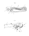
Figure 1 is a side elevation view of an item of sports footwear constructed in accordance with the present invention, -
Figure 2 is a schematic front perspective view of a protection element of the footwear ofFigure 1 , in a first operating condition, -
Figure 3 is a schematic front perspective view of the protection element ofFigure 2 , in a second operating condition; -
Figure 4 is a schematic exploded view of the protection element ofFigure 2 . - In the appended Figures, an item of sports footwear which is particularly suitable for motorcycling and competitive motorcycling and which is constructed in accordance with the present invention, is generally designated 1.
- The footwear 1, which is in the form of a boot, comprises a sole 2, to which there is fixed an upper 3 in accordance with methods which are conventional per se. There are defined on the sole 2 a tread surface 2a of the footwear 1 and an edge 2b which extends peripherally from the tread surface towards the upper 3. There is further identified on the footwear 1 a toe region 4 and opposing lateral sides which are defined as the inner side and outer side, respectively, the outer side being designated 5.
- The footwear 1 comprises a
protection element 10 which is releasably fitted on a portion of the upper 3, for protection of it and the sole 2, in the region of an outer lateral region 6 of the footwear 1 extending from the toe region 4 along the outer side 5. - The
protection element 10 comprises a first and a second portion which are designated 11 and 12, respectively, which are substantially rigid and between which there extends a highly deformable region 13 which is firmly connected thereto to allow a pivoting movement of the first portion 11 relative to thesecond portion 12 about an axis which is substantially coincident with the axis of metatarsal articulation of the foot of a user of the footwear 1. - The
protection element 10 is preferably a unitary body which is produced in one piece by means of a process for injection-moulding and pressing polymer material. The polymer material may be selected from any one of the materials used in the sector for this purpose, although it is preferred to use thermoplastic polyurethanes (TPU) or polyamides, also charged with reinforcement fibres. - The
protection element 10 is preferably fixed to the upper 3 by means of a screw 25 which acts on the first portion 11 and a pair ofscrews 26 and 27 which act on thesecond portion 12. - To that end, there is formed in the first portion 11 a through-
hole 28 whilst there is preferably formed in the second portion 12 a pair of through-slots second portion 12 both with respect to the upper 3 and with respect to the first portion 11. - It is further preferable for the
slot 29 and the respective screw 26 to be protected by a cover element 31 which is engagingly received in aseat 32, which is defined in thesecond portion 12, by way of engagement means 33. - There are further identified on the
protection element 10 anupper side 14 and alower side 15, which extend in a generally parallel manner in a position remote from and near the tread surface 2a of the sole 2, respectively. - The highly deformable region 13 comprises a
slit 16 for partial separation between the first portion 11 and thesecond portion 12, whichslit 16 extends from theupper side 14 of theprotection element 10, where it opens outwards, towards thelower side 15, but without acting on it directly. - The highly deformable region 13 further comprises a
bridge portion 17 which extends between the first portion 11 and thesecond portion 12 and which is defined between theslit 16 and thelower side 15 of theprotection element 10. - The
bridge portion 17 advantageously has a thickness which is substantially similar to that of the first andsecond portions 11, 12. - Since the
protection element 10 is advantageously a unitary body, thebridge portion 17 is constructed from the same material as theportions 11 and 12, therefore having the same mechanical characteristics. Owing to the reduced section thereof, however, it is sufficiently deformable to allow a pivoting movement of the first portion 11 relative to thesecond portion 12. - The
slit 16 is delimited byopposing surfaces second portions 11, 12, respectively, which are connected in the region of a closedend 20 of theslit 16. In the region of the closedend 20, the profile of theslit 16 is substantially semi-circular. - Similarly, the profile of the
slit 16 takes up a substantially semi-circular formation at aregion 21 thereof adjacent to thebridge portion 17. That arrangement allows the distribution in a more uniform manner of any stresses resulting from the pivoting movement of the first andsecond portions 11, 12 in the region of thebridge portion 17 and the region of the first portion 11 between theslit 16 and thelower side 15. - It will further be appreciated that, at a predetermined value of angular movement of the first portion 11 with respect to the
second portion 12, thesurfaces surfaces second portion 12 and the spacing between them, when theslit 16 is dimensioned, is advantageously defined in accordance with the maximum pivoting movement required. - This feature advantageously allows prevention of excessive flexion behind the toe region 4 of the footwear 1, thereby safeguarding the integrity of the front portion of the foot.
- Means for guiding the pivoting movement are further provided between the first and the
second portion 11 and 12. - Preferably, those guide means comprise an
appendage 22 extending from thesurface 18 of the first portion 11 towards thesecond portion 12, as well as aseat 23 which is formed in thesecond portion 12 in order to house theappendage 22 for sliding engagement. - The
seat 23 comprises a recess which is formed in thesecond portion 12 on the side facing the upper 3 so that theappendage 22 is guided for sliding between thesecond portion 12 and the upper 3. - In this manner, it is possible for the first portion 11 and the
second portion 12 to be maintained substantially so as to be complanate both when remote from and when near each other following the pivoting movement. - During the walking movement of the user, the footwear 1 moves from a first operative configuration, in which the first portion 11 and the
second portion 12 are pivoted away from each other (Figures 1 and 2 ), into a second operative configuration, in which the first portion 11 and thesecond portion 12 are pivoted towards each other, as far as mutual contact in the region of thesurfaces 18, 19 (Figure 3 ), respectively. - Therefore, the present invention solves the problem set out above with reference to the prior art mentioned, simultaneously providing a number of other advantages, including the fact that the thickness of the protection element can advantageously be kept small in the region of the articulation between the two rigid portions, and consequently the axis of articulation of the protection element can be positioned in the region of the axis of metatarsal articulation of the foot.
- This also allows, in addition to a more natural walking action, greater sensitivity to be achieved when changing the gears of the motorcycle.
- Another advantage is provided by the extent of the protection element, whose surface can be advantageously and correctly dimensioned so as to protect the entire region of the upper and the sole that is potentially exposed to abrasions.
- Furthermore, the protection element is advantageously formed by means of a single injection-moulding and pressing operation which is relatively simple and inexpensive per se.
Claims (11)
- Sports footwear (1), particularly for motorcycling, comprising a protection element (10) which is fitted on a lateral toe region (6) of the footwear and includes a first portion (11) and a second portion (12) which are substantially rigid and are associated with one another, characterized in that a region (13) with a high degree of deformability is defined in the protection element, extending between the first and second portions, and is connected firmly thereto to allow a pivoting movement of the first portion relative to the second portion.
- Footwear according to Claim 1 in which the protection element (10) is a unitary body.
- Footwear according to Claim 1 or Claim 2 in which the region (13) with a high degree of deformability comprises a slit (16) which separates the first and second portions and which extends from an upper side (14) of the protection element remote from a tread surface (2a) of the footwear towards a lower side (15) of the protection element in the vicinity of the tread surface, as well as a bridge portion (17) which extends between the first and second portions and is defined between the slit and the lower side of the protection element.
- Footwear according to Claim 3 in which the slit (16) has a substantially semicircular profile (21) in the region of the bridge portion.
- Footwear according to Claim 3 or Claim 4 in which the slit (16) has a substantially semicircular profile in the region of a closed end (20) thereof remote from the upper side (14).
- Footwear according to any one of Claims 3 to 5 in which the opposed surfaces (18, 19) of the first and second portions (11, 12) which delimit the slit (16) define means for limiting the pivoting movement.
- Footwear according to any one of the preceding claims in which guide means for the pivoting movement are provided between the first and second portions.
- Footwear according to Claim 7 in which the guide means comprise an appendage (22) extending from one of the first and second portions towards the other of the first and second portions and a seat (23) formed in the other of the first and second portions to house the appendage slidingly.
- Footwear according to Claim 8 in which the seat (23) comprises a recess which is formed in the other of the first and second portions on the side facing an upper (3) of the footwear so that the appendage (22) is guided for sliding between the other of the first and second portions and the upper.
- Footwear according to any one of the preceding claims in which the first and second portions (11, 12) are connected, separately and releasably, to the lateral toe region of the footwear.
- A protection element (10) for sports footwear, particularly for motorcycling, which can be fitted on a lateral toe region (6) of the footwear and includes a first portion (11) and a second portion (12) which are substantially rigid and are associated with one another, characterized in that a region (13) with a high degree of deformability is defined in the protection element between the first and second portions, and is connected firmly thereto to allow a pivoting movement of the first portion relative to the second portion.
Applications Claiming Priority (1)
| Application Number | Priority Date | Filing Date | Title |
|---|---|---|---|
| ITPD2009A000074A IT1393726B1 (en) | 2009-03-31 | 2009-03-31 | SPORTS FOOTWEAR, PARTICULARLY FOR THE PRACTICE OF MOTORCYCLING |
Publications (2)
| Publication Number | Publication Date |
|---|---|
| EP2236050A1 true EP2236050A1 (en) | 2010-10-06 |
| EP2236050B1 EP2236050B1 (en) | 2017-05-24 |
Family
ID=41426977
Family Applications (1)
| Application Number | Title | Priority Date | Filing Date |
|---|---|---|---|
| EP10158099.1A Active EP2236050B1 (en) | 2009-03-31 | 2010-03-29 | Sports footwear, particularly for motorcycling |
Country Status (3)
| Country | Link |
|---|---|
| EP (1) | EP2236050B1 (en) |
| ES (1) | ES2638040T3 (en) |
| IT (1) | IT1393726B1 (en) |
Cited By (1)
| Publication number | Priority date | Publication date | Assignee | Title |
|---|---|---|---|---|
| ITTV20120186A1 (en) * | 2012-09-28 | 2014-03-29 | Alpinestars Res Srl | SPORTS FOOTWEAR |
Citations (3)
| Publication number | Priority date | Publication date | Assignee | Title |
|---|---|---|---|---|
| DE3643057A1 (en) * | 1986-12-17 | 1988-06-30 | Bayerische Motoren Werke Ag | Motorcycle boot |
| GB2363969A (en) * | 2000-06-28 | 2002-01-16 | Stilma Srl | Guard attachment with projecting inserts |
| US6820354B1 (en) * | 2002-06-19 | 2004-11-23 | Jolly Scarpe S.P.A. | Sport shoe provided with a device to control the flexion of the toe |
-
2009
- 2009-03-31 IT ITPD2009A000074A patent/IT1393726B1/en active
-
2010
- 2010-03-29 EP EP10158099.1A patent/EP2236050B1/en active Active
- 2010-03-29 ES ES10158099.1T patent/ES2638040T3/en active Active
Patent Citations (3)
| Publication number | Priority date | Publication date | Assignee | Title |
|---|---|---|---|---|
| DE3643057A1 (en) * | 1986-12-17 | 1988-06-30 | Bayerische Motoren Werke Ag | Motorcycle boot |
| GB2363969A (en) * | 2000-06-28 | 2002-01-16 | Stilma Srl | Guard attachment with projecting inserts |
| US6820354B1 (en) * | 2002-06-19 | 2004-11-23 | Jolly Scarpe S.P.A. | Sport shoe provided with a device to control the flexion of the toe |
Cited By (5)
| Publication number | Priority date | Publication date | Assignee | Title |
|---|---|---|---|---|
| ITTV20120186A1 (en) * | 2012-09-28 | 2014-03-29 | Alpinestars Res Srl | SPORTS FOOTWEAR |
| WO2014049535A1 (en) * | 2012-09-28 | 2014-04-03 | Alpinestars Research Srl | Sports footwear |
| CN104684428A (en) * | 2012-09-28 | 2015-06-03 | 阿尔皮纳塔尔研究公司 | Sports footwear |
| AU2013322174B2 (en) * | 2012-09-28 | 2017-05-11 | Alpinestars Research S.p.A. | Sports footwear |
| US9675138B2 (en) | 2012-09-28 | 2017-06-13 | Alpinestars Research Srl | Sports footwear |
Also Published As
| Publication number | Publication date |
|---|---|
| ITPD20090074A1 (en) | 2010-10-01 |
| EP2236050B1 (en) | 2017-05-24 |
| IT1393726B1 (en) | 2012-05-08 |
| ES2638040T3 (en) | 2017-10-18 |
Similar Documents
| Publication | Publication Date | Title |
|---|---|---|
| US10575585B2 (en) | Supporting element for shoes | |
| CN101756419B (en) | Sole | |
| EP1954154B1 (en) | Flexible shank for an article of footwear | |
| CN102026595A (en) | Leg support | |
| CA3055740C (en) | Hockey skate | |
| US7818900B2 (en) | Inner boot, particularly for a sports shoe | |
| EP2925174B1 (en) | Tuning elements for footwear | |
| US3408752A (en) | Sports boot | |
| EP2833752B1 (en) | Ski boot | |
| US7140127B2 (en) | Body for a skate boot | |
| EP0471447B1 (en) | Footwear sole | |
| EP2236050B1 (en) | Sports footwear, particularly for motorcycling | |
| US4570364A (en) | Article of athletic footwear, especially a ski boot | |
| EP2777415B1 (en) | Skate boot having a tendon guard with a recess | |
| CN109805493A (en) | A kind of diabetes shoes of socks vamp | |
| US20120186108A1 (en) | Device for adjusting the position of the bootleg with respect to the shell, particularly for ski boots | |
| CA2809462C (en) | Skate boot having a tendon guard with a recess | |
| US20140361514A1 (en) | Safety ski binding system | |
| EP2710911B1 (en) | Ski boots with a device for adjusting the position of the bootleg with respect to the shell | |
| WO2006085345A1 (en) | Sport shoe with a movable insert located inside the sole and suitable for changing the features of the latter when it hits the ground | |
| CN201813917U (en) | Metallic shoe | |
| US7984570B2 (en) | Sports shoe, such as a ski boot, snowboarding boot, trekking boot or suchlike | |
| JP5438932B2 (en) | Shoe toe | |
| WO2013078483A1 (en) | Gumboot with integral metatarsal guard | |
| EP3735853A1 (en) | Rear entry sports footwear, more particularly rear entry ski boot |
Legal Events
| Date | Code | Title | Description |
|---|---|---|---|
| PUAI | Public reference made under article 153(3) epc to a published international application that has entered the european phase |
Free format text: ORIGINAL CODE: 0009012 |
|
| AK | Designated contracting states |
Kind code of ref document: A1 Designated state(s): AT BE BG CH CY CZ DE DK EE ES FI FR GB GR HR HU IE IS IT LI LT LU LV MC MK MT NL NO PL PT RO SE SI SK SM TR |
|
| AX | Request for extension of the european patent |
Extension state: AL BA ME RS |
|
| 17P | Request for examination filed |
Effective date: 20110324 |
|
| RAP1 | Party data changed (applicant data changed or rights of an application transferred) |
Owner name: TCX S.R.L. |
|
| GRAP | Despatch of communication of intention to grant a patent |
Free format text: ORIGINAL CODE: EPIDOSNIGR1 |
|
| INTG | Intention to grant announced |
Effective date: 20170103 |
|
| GRAS | Grant fee paid |
Free format text: ORIGINAL CODE: EPIDOSNIGR3 |
|
| GRAA | (expected) grant |
Free format text: ORIGINAL CODE: 0009210 |
|
| AK | Designated contracting states |
Kind code of ref document: B1 Designated state(s): AT BE BG CH CY CZ DE DK EE ES FI FR GB GR HR HU IE IS IT LI LT LU LV MC MK MT NL NO PL PT RO SE SI SK SM TR |
|
| REG | Reference to a national code |
Ref country code: GB Ref legal event code: FG4D |
|
| REG | Reference to a national code |
Ref country code: CH Ref legal event code: EP |
|
| REG | Reference to a national code |
Ref country code: IE Ref legal event code: FG4D |
|
| REG | Reference to a national code |
Ref country code: AT Ref legal event code: REF Ref document number: 895558 Country of ref document: AT Kind code of ref document: T Effective date: 20170615 |
|
| REG | Reference to a national code |
Ref country code: DE Ref legal event code: R096 Ref document number: 602010042518 Country of ref document: DE |
|
| REG | Reference to a national code |
Ref country code: NL Ref legal event code: MP Effective date: 20170524 |
|
| REG | Reference to a national code |
Ref country code: LT Ref legal event code: MG4D |
|
| REG | Reference to a national code |
Ref country code: ES Ref legal event code: FG2A Ref document number: 2638040 Country of ref document: ES Kind code of ref document: T3 Effective date: 20171018 |
|
| PG25 | Lapsed in a contracting state [announced via postgrant information from national office to epo] |
Ref country code: FI Free format text: LAPSE BECAUSE OF FAILURE TO SUBMIT A TRANSLATION OF THE DESCRIPTION OR TO PAY THE FEE WITHIN THE PRESCRIBED TIME-LIMIT Effective date: 20170524 Ref country code: HR Free format text: LAPSE BECAUSE OF FAILURE TO SUBMIT A TRANSLATION OF THE DESCRIPTION OR TO PAY THE FEE WITHIN THE PRESCRIBED TIME-LIMIT Effective date: 20170524 Ref country code: GR Free format text: LAPSE BECAUSE OF FAILURE TO SUBMIT A TRANSLATION OF THE DESCRIPTION OR TO PAY THE FEE WITHIN THE PRESCRIBED TIME-LIMIT Effective date: 20170825 Ref country code: NO Free format text: LAPSE BECAUSE OF FAILURE TO SUBMIT A TRANSLATION OF THE DESCRIPTION OR TO PAY THE FEE WITHIN THE PRESCRIBED TIME-LIMIT Effective date: 20170824 Ref country code: LT Free format text: LAPSE BECAUSE OF FAILURE TO SUBMIT A TRANSLATION OF THE DESCRIPTION OR TO PAY THE FEE WITHIN THE PRESCRIBED TIME-LIMIT Effective date: 20170524 |
|
| PG25 | Lapsed in a contracting state [announced via postgrant information from national office to epo] |
Ref country code: BG Free format text: LAPSE BECAUSE OF FAILURE TO SUBMIT A TRANSLATION OF THE DESCRIPTION OR TO PAY THE FEE WITHIN THE PRESCRIBED TIME-LIMIT Effective date: 20170824 Ref country code: IS Free format text: LAPSE BECAUSE OF FAILURE TO SUBMIT A TRANSLATION OF THE DESCRIPTION OR TO PAY THE FEE WITHIN THE PRESCRIBED TIME-LIMIT Effective date: 20170924 Ref country code: LV Free format text: LAPSE BECAUSE OF FAILURE TO SUBMIT A TRANSLATION OF THE DESCRIPTION OR TO PAY THE FEE WITHIN THE PRESCRIBED TIME-LIMIT Effective date: 20170524 Ref country code: SE Free format text: LAPSE BECAUSE OF FAILURE TO SUBMIT A TRANSLATION OF THE DESCRIPTION OR TO PAY THE FEE WITHIN THE PRESCRIBED TIME-LIMIT Effective date: 20170524 Ref country code: NL Free format text: LAPSE BECAUSE OF FAILURE TO SUBMIT A TRANSLATION OF THE DESCRIPTION OR TO PAY THE FEE WITHIN THE PRESCRIBED TIME-LIMIT Effective date: 20170524 |
|
| PG25 | Lapsed in a contracting state [announced via postgrant information from national office to epo] |
Ref country code: CZ Free format text: LAPSE BECAUSE OF FAILURE TO SUBMIT A TRANSLATION OF THE DESCRIPTION OR TO PAY THE FEE WITHIN THE PRESCRIBED TIME-LIMIT Effective date: 20170524 Ref country code: EE Free format text: LAPSE BECAUSE OF FAILURE TO SUBMIT A TRANSLATION OF THE DESCRIPTION OR TO PAY THE FEE WITHIN THE PRESCRIBED TIME-LIMIT Effective date: 20170524 Ref country code: RO Free format text: LAPSE BECAUSE OF FAILURE TO SUBMIT A TRANSLATION OF THE DESCRIPTION OR TO PAY THE FEE WITHIN THE PRESCRIBED TIME-LIMIT Effective date: 20170524 Ref country code: DK Free format text: LAPSE BECAUSE OF FAILURE TO SUBMIT A TRANSLATION OF THE DESCRIPTION OR TO PAY THE FEE WITHIN THE PRESCRIBED TIME-LIMIT Effective date: 20170524 Ref country code: SK Free format text: LAPSE BECAUSE OF FAILURE TO SUBMIT A TRANSLATION OF THE DESCRIPTION OR TO PAY THE FEE WITHIN THE PRESCRIBED TIME-LIMIT Effective date: 20170524 |
|
| REG | Reference to a national code |
Ref country code: DE Ref legal event code: R097 Ref document number: 602010042518 Country of ref document: DE |
|
| PG25 | Lapsed in a contracting state [announced via postgrant information from national office to epo] |
Ref country code: PL Free format text: LAPSE BECAUSE OF FAILURE TO SUBMIT A TRANSLATION OF THE DESCRIPTION OR TO PAY THE FEE WITHIN THE PRESCRIBED TIME-LIMIT Effective date: 20170524 Ref country code: SM Free format text: LAPSE BECAUSE OF FAILURE TO SUBMIT A TRANSLATION OF THE DESCRIPTION OR TO PAY THE FEE WITHIN THE PRESCRIBED TIME-LIMIT Effective date: 20170524 |
|
| REG | Reference to a national code |
Ref country code: FR Ref legal event code: PLFP Year of fee payment: 9 |
|
| PLBE | No opposition filed within time limit |
Free format text: ORIGINAL CODE: 0009261 |
|
| STAA | Information on the status of an ep patent application or granted ep patent |
Free format text: STATUS: NO OPPOSITION FILED WITHIN TIME LIMIT |
|
| 26N | No opposition filed |
Effective date: 20180227 |
|
| PG25 | Lapsed in a contracting state [announced via postgrant information from national office to epo] |
Ref country code: SI Free format text: LAPSE BECAUSE OF FAILURE TO SUBMIT A TRANSLATION OF THE DESCRIPTION OR TO PAY THE FEE WITHIN THE PRESCRIBED TIME-LIMIT Effective date: 20170524 |
|
| PG25 | Lapsed in a contracting state [announced via postgrant information from national office to epo] |
Ref country code: MC Free format text: LAPSE BECAUSE OF FAILURE TO SUBMIT A TRANSLATION OF THE DESCRIPTION OR TO PAY THE FEE WITHIN THE PRESCRIBED TIME-LIMIT Effective date: 20170524 |
|
| REG | Reference to a national code |
Ref country code: IE Ref legal event code: MM4A |
|
| PG25 | Lapsed in a contracting state [announced via postgrant information from national office to epo] |
Ref country code: LU Free format text: LAPSE BECAUSE OF NON-PAYMENT OF DUE FEES Effective date: 20180329 |
|
| PG25 | Lapsed in a contracting state [announced via postgrant information from national office to epo] |
Ref country code: IE Free format text: LAPSE BECAUSE OF NON-PAYMENT OF DUE FEES Effective date: 20180329 |
|
| PG25 | Lapsed in a contracting state [announced via postgrant information from national office to epo] |
Ref country code: MT Free format text: LAPSE BECAUSE OF NON-PAYMENT OF DUE FEES Effective date: 20180329 |
|
| REG | Reference to a national code |
Ref country code: AT Ref legal event code: UEP Ref document number: 895558 Country of ref document: AT Kind code of ref document: T Effective date: 20170524 |
|
| PG25 | Lapsed in a contracting state [announced via postgrant information from national office to epo] |
Ref country code: TR Free format text: LAPSE BECAUSE OF FAILURE TO SUBMIT A TRANSLATION OF THE DESCRIPTION OR TO PAY THE FEE WITHIN THE PRESCRIBED TIME-LIMIT Effective date: 20170524 |
|
| PG25 | Lapsed in a contracting state [announced via postgrant information from national office to epo] |
Ref country code: PT Free format text: LAPSE BECAUSE OF FAILURE TO SUBMIT A TRANSLATION OF THE DESCRIPTION OR TO PAY THE FEE WITHIN THE PRESCRIBED TIME-LIMIT Effective date: 20170524 Ref country code: HU Free format text: LAPSE BECAUSE OF FAILURE TO SUBMIT A TRANSLATION OF THE DESCRIPTION OR TO PAY THE FEE WITHIN THE PRESCRIBED TIME-LIMIT; INVALID AB INITIO Effective date: 20100329 |
|
| PG25 | Lapsed in a contracting state [announced via postgrant information from national office to epo] |
Ref country code: MK Free format text: LAPSE BECAUSE OF NON-PAYMENT OF DUE FEES Effective date: 20170524 Ref country code: CY Free format text: LAPSE BECAUSE OF FAILURE TO SUBMIT A TRANSLATION OF THE DESCRIPTION OR TO PAY THE FEE WITHIN THE PRESCRIBED TIME-LIMIT Effective date: 20170524 |
|
| REG | Reference to a national code |
Ref country code: DE Ref legal event code: R081 Ref document number: 602010042518 Country of ref document: DE Owner name: DAINESE S.P.A., COLCERESA, IT Free format text: FORMER OWNER: TCX S.R.L., MONTEBELLUNA, IT |
|
| REG | Reference to a national code |
Ref country code: GB Ref legal event code: 732E Free format text: REGISTERED BETWEEN 20220303 AND 20220309 |
|
| REG | Reference to a national code |
Ref country code: BE Ref legal event code: PD Owner name: DIANESE S.P.A.; IT Free format text: DETAILS ASSIGNMENT: CHANGE OF OWNER(S), ASSIGNMENT; FORMER OWNER NAME: TCX S.R.L. Effective date: 20220316 Ref country code: BE Ref legal event code: PD Owner name: DIANESE S.P.A.; IT Free format text: DETAILS ASSIGNMENT: CHANGE OF OWNER(S), ASSIGNMENT Effective date: 20220316 |
|
| REG | Reference to a national code |
Ref country code: BE Ref legal event code: PD Owner name: DIANESE S.P.A.; IT Free format text: DETAILS ASSIGNMENT: CHANGE OF OWNER(S), ASSIGNMENT; FORMER OWNER NAME: TCX S.R.L. Effective date: 20220316 |
|
| REG | Reference to a national code |
Ref country code: AT Ref legal event code: PC Ref document number: 895558 Country of ref document: AT Kind code of ref document: T Owner name: DAINESE S.P.A., IT Effective date: 20220419 |
|
| REG | Reference to a national code |
Ref country code: ES Ref legal event code: PC2A Owner name: DAINESE S.P.A. Effective date: 20220712 |
|
| PGFP | Annual fee paid to national office [announced via postgrant information from national office to epo] |
Ref country code: AT Payment date: 20230331 Year of fee payment: 14 |
|
| PGFP | Annual fee paid to national office [announced via postgrant information from national office to epo] |
Ref country code: GB Payment date: 20230324 Year of fee payment: 14 Ref country code: BE Payment date: 20230330 Year of fee payment: 14 |
|
| PGFP | Annual fee paid to national office [announced via postgrant information from national office to epo] |
Ref country code: ES Payment date: 20230420 Year of fee payment: 14 Ref country code: CH Payment date: 20230401 Year of fee payment: 14 |
|
| REG | Reference to a national code |
Ref country code: CH Ref legal event code: PL |
|
| REG | Reference to a national code |
Ref country code: AT Ref legal event code: MM01 Ref document number: 895558 Country of ref document: AT Kind code of ref document: T Effective date: 20240329 |
|
| GBPC | Gb: european patent ceased through non-payment of renewal fee |
Effective date: 20240329 |
|
| REG | Reference to a national code |
Ref country code: BE Ref legal event code: MM Effective date: 20240331 |
|
| PG25 | Lapsed in a contracting state [announced via postgrant information from national office to epo] |
Ref country code: BE Free format text: LAPSE BECAUSE OF NON-PAYMENT OF DUE FEES Effective date: 20240331 |
|
| PG25 | Lapsed in a contracting state [announced via postgrant information from national office to epo] |
Ref country code: GB Free format text: LAPSE BECAUSE OF NON-PAYMENT OF DUE FEES Effective date: 20240329 |
|
| PG25 | Lapsed in a contracting state [announced via postgrant information from national office to epo] |
Ref country code: AT Free format text: LAPSE BECAUSE OF NON-PAYMENT OF DUE FEES Effective date: 20240329 |
|
| PG25 | Lapsed in a contracting state [announced via postgrant information from national office to epo] |
Ref country code: GB Free format text: LAPSE BECAUSE OF NON-PAYMENT OF DUE FEES Effective date: 20240329 Ref country code: BE Free format text: LAPSE BECAUSE OF NON-PAYMENT OF DUE FEES Effective date: 20240331 Ref country code: AT Free format text: LAPSE BECAUSE OF NON-PAYMENT OF DUE FEES Effective date: 20240329 Ref country code: CH Free format text: LAPSE BECAUSE OF NON-PAYMENT OF DUE FEES Effective date: 20240331 |
|
| REG | Reference to a national code |
Ref country code: ES Ref legal event code: FD2A Effective date: 20250508 |
|
| PGFP | Annual fee paid to national office [announced via postgrant information from national office to epo] |
Ref country code: DE Payment date: 20250408 Year of fee payment: 16 |
|
| PG25 | Lapsed in a contracting state [announced via postgrant information from national office to epo] |
Ref country code: ES Free format text: LAPSE BECAUSE OF NON-PAYMENT OF DUE FEES Effective date: 20240330 |
|
| PGFP | Annual fee paid to national office [announced via postgrant information from national office to epo] |
Ref country code: IT Payment date: 20250331 Year of fee payment: 16 |
|
| PGFP | Annual fee paid to national office [announced via postgrant information from national office to epo] |
Ref country code: FR Payment date: 20250408 Year of fee payment: 16 |