EP2235378B1 - A fluid-mechanical machine, in particular a centrifugal fan - Google Patents
A fluid-mechanical machine, in particular a centrifugal fan Download PDFInfo
- Publication number
- EP2235378B1 EP2235378B1 EP08862665A EP08862665A EP2235378B1 EP 2235378 B1 EP2235378 B1 EP 2235378B1 EP 08862665 A EP08862665 A EP 08862665A EP 08862665 A EP08862665 A EP 08862665A EP 2235378 B1 EP2235378 B1 EP 2235378B1
- Authority
- EP
- European Patent Office
- Prior art keywords
- machine
- flow
- fluid
- ducts
- section
- Prior art date
- Legal status (The legal status is an assumption and is not a legal conclusion. Google has not performed a legal analysis and makes no representation as to the accuracy of the status listed.)
- Active
Links
- 239000012530 fluid Substances 0.000 claims abstract description 17
- 239000002250 absorbent Substances 0.000 description 1
- 230000030279 gene silencing Effects 0.000 description 1
- 238000010438 heat treatment Methods 0.000 description 1
- 239000000463 material Substances 0.000 description 1
- 238000005259 measurement Methods 0.000 description 1
- 239000000203 mixture Substances 0.000 description 1
- 238000011144 upstream manufacturing Methods 0.000 description 1
Images


Classifications
-
- F—MECHANICAL ENGINEERING; LIGHTING; HEATING; WEAPONS; BLASTING
- F04—POSITIVE - DISPLACEMENT MACHINES FOR LIQUIDS; PUMPS FOR LIQUIDS OR ELASTIC FLUIDS
- F04D—NON-POSITIVE-DISPLACEMENT PUMPS
- F04D29/00—Details, component parts, or accessories
- F04D29/40—Casings; Connections of working fluid
- F04D29/42—Casings; Connections of working fluid for radial or helico-centrifugal pumps
- F04D29/4206—Casings; Connections of working fluid for radial or helico-centrifugal pumps especially adapted for elastic fluid pumps
- F04D29/4226—Fan casings
- F04D29/4253—Fan casings with axial entry and discharge
-
- F—MECHANICAL ENGINEERING; LIGHTING; HEATING; WEAPONS; BLASTING
- F04—POSITIVE - DISPLACEMENT MACHINES FOR LIQUIDS; PUMPS FOR LIQUIDS OR ELASTIC FLUIDS
- F04D—NON-POSITIVE-DISPLACEMENT PUMPS
- F04D17/00—Radial-flow pumps, e.g. centrifugal pumps; Helico-centrifugal pumps
- F04D17/08—Centrifugal pumps
- F04D17/16—Centrifugal pumps for displacing without appreciable compression
- F04D17/165—Axial entry and discharge
-
- F—MECHANICAL ENGINEERING; LIGHTING; HEATING; WEAPONS; BLASTING
- F04—POSITIVE - DISPLACEMENT MACHINES FOR LIQUIDS; PUMPS FOR LIQUIDS OR ELASTIC FLUIDS
- F04D—NON-POSITIVE-DISPLACEMENT PUMPS
- F04D29/00—Details, component parts, or accessories
- F04D29/40—Casings; Connections of working fluid
- F04D29/42—Casings; Connections of working fluid for radial or helico-centrifugal pumps
- F04D29/426—Casings; Connections of working fluid for radial or helico-centrifugal pumps especially adapted for liquid pumps
-
- F—MECHANICAL ENGINEERING; LIGHTING; HEATING; WEAPONS; BLASTING
- F04—POSITIVE - DISPLACEMENT MACHINES FOR LIQUIDS; PUMPS FOR LIQUIDS OR ELASTIC FLUIDS
- F04D—NON-POSITIVE-DISPLACEMENT PUMPS
- F04D29/00—Details, component parts, or accessories
- F04D29/40—Casings; Connections of working fluid
- F04D29/42—Casings; Connections of working fluid for radial or helico-centrifugal pumps
- F04D29/44—Fluid-guiding means, e.g. diffusers
- F04D29/441—Fluid-guiding means, e.g. diffusers especially adapted for elastic fluid pumps
-
- F—MECHANICAL ENGINEERING; LIGHTING; HEATING; WEAPONS; BLASTING
- F04—POSITIVE - DISPLACEMENT MACHINES FOR LIQUIDS; PUMPS FOR LIQUIDS OR ELASTIC FLUIDS
- F04D—NON-POSITIVE-DISPLACEMENT PUMPS
- F04D29/00—Details, component parts, or accessories
- F04D29/40—Casings; Connections of working fluid
- F04D29/42—Casings; Connections of working fluid for radial or helico-centrifugal pumps
- F04D29/44—Fluid-guiding means, e.g. diffusers
- F04D29/441—Fluid-guiding means, e.g. diffusers especially adapted for elastic fluid pumps
- F04D29/444—Bladed diffusers
-
- F—MECHANICAL ENGINEERING; LIGHTING; HEATING; WEAPONS; BLASTING
- F04—POSITIVE - DISPLACEMENT MACHINES FOR LIQUIDS; PUMPS FOR LIQUIDS OR ELASTIC FLUIDS
- F04D—NON-POSITIVE-DISPLACEMENT PUMPS
- F04D29/00—Details, component parts, or accessories
- F04D29/40—Casings; Connections of working fluid
- F04D29/42—Casings; Connections of working fluid for radial or helico-centrifugal pumps
- F04D29/44—Fluid-guiding means, e.g. diffusers
- F04D29/445—Fluid-guiding means, e.g. diffusers especially adapted for liquid pumps
-
- F—MECHANICAL ENGINEERING; LIGHTING; HEATING; WEAPONS; BLASTING
- F04—POSITIVE - DISPLACEMENT MACHINES FOR LIQUIDS; PUMPS FOR LIQUIDS OR ELASTIC FLUIDS
- F04D—NON-POSITIVE-DISPLACEMENT PUMPS
- F04D29/00—Details, component parts, or accessories
- F04D29/40—Casings; Connections of working fluid
- F04D29/42—Casings; Connections of working fluid for radial or helico-centrifugal pumps
- F04D29/44—Fluid-guiding means, e.g. diffusers
- F04D29/445—Fluid-guiding means, e.g. diffusers especially adapted for liquid pumps
- F04D29/448—Fluid-guiding means, e.g. diffusers especially adapted for liquid pumps bladed diffusers
Definitions
- the present invention relates to a fluid-mechanical machine having the characteristics set out in the preamble to main Claim 1.
- a fluid-mechanical machine having the features outlined above is known from US 3289695 (closest prior art).
- FR-A-2422053 and DE-A-3842826 are also prior art to the present invention.
- Fluid-mechanical machines of the type indicated are typically provided with a bladed rotor which is supported rotatably in a manifold in which an inlet section and an output section are defined for the operative fluid processed by the machine. Compressors, fans and pumps are given as examples of operative machines. These fluid-mechanical machines are distinguished by fluid intake and delivery sections that are far apart and in general are arranged in the region of the rotation axis of the rotor and in a radial position remote from the axis, respectively, according to whether they are operative or power machines.
- a principal object of the invention is to provide a fluid-mechanical machine which is devised structurally and functionally to achieve an improvement in functional capacity in terms of efficiency in the processing of the operative fluid output from or entering the machine, prior to the supply of the flow to other operative stages that are provided for downstream of the fluid-mechanical machine in specific applications.
- an example of a fluid-mechanical machine according to the invention is constructed as an operative machine and is designed, in particular, as a centrifugal fan arranged for processing an aeriform fluid.
- a typical application may be that of a centrifugal fan for the pre-mixing of an air-gas mixture to be supplied to a gas burner which is arranged downstream of the fan with respect to the direction of the flow.
- the fan comprises a bladed rotor 2 with a rotor-housing manifold 3 in which an intake section 4 and a delivery section 5 of the fan are formed.
- the rotor 2 can be rotated about a rotation axis X by a drive means (not shown), for example, an electric motor onto the drive shaft of which the rotor is keyed.
- a drive means for example, an electric motor onto the drive shaft of which the rotor is keyed.
- the intake section 4 is provided in the region of the axis X and comprises an opening 4a coaxial with the axis X.
- the delivery section 5, is defined in the region of a circumferential profile located downstream of the outside diameter of the rotor and can be approximated to a cylindrical lateral surface the circular base of which is defined by the above-mentioned circumferential profile.
- the fan unit contains first diverter means, indicated 10, for diverting the fluid that is delivered through the delivery section 5 of the fan and second, separate and distinct diverter means, indicated 11, for diverting the flow of operative fluid drawn in from outside the fan towards the intake section 4.
- the diverter means 10, 11 are selected to have an extent and shape such that the flow at the delivery section 5 of the fan crosses the flow of fluid directed towards the intake section 4, as shown schematically in Figure 3 , in which the flows are directed separately and distinctly from one another by the first and second diverter means.
- the first diverter means 10 comprise a respective plurality of ducts, all indicated 12, which extend in the region of the delivery section 5 of the fan, beyond the outside diameter of the rotor 2, to connect the delivery section with the area outside the fan.
- each duct 12 is distributed circumferentially, downstream of the delivery section 5, at preselected angular intervals, in particular at regular angular intervals. Moreover, each duct 12 has, at one of its ends with respect to the direction of the flow, an inlet opening 12a for the fluid (supplied by the delivery section of the fan) in which the flow has a predominant radial component, and an output opening 12b at the opposite end, in which the flow has a predominant axial component.
- the second diverter means 11 in turn comprise a respective plurality of ducts, all indicated 13, which are positioned alternately with the ducts 12 so that, in the region M in which the flows cross, a duct 13 is interposed between a pair of adjacent ducts 12.
- each duct 13 has an inlet opening 13a which is open to the area outside the fan for the admission of the fluid thereto, and an opposed outlet opening 13b communicating with a chamber 15 which in turn is connected to the intake section 4 of the fan.
- Stator blades, indicated 20, are also formed in the chamber 15 for suitably diverting the flow of the operative fluid towards the intake section 4; optionally, the stator blades 20 can impart to the flow a pre-rotation component which is produced by the curved profiles of the stator blades.
- the ducts 13 are also preferably distributed along a circumferential profile which is concentric with the rotor axis and is located downstream of the delivery section 5. Moreover, a distribution of ducts at regular angular intervals is preferred.
- the inlet opening 13a of each duct is such as to impart a predominant axial component to the flow which is subsequently deflected to reach the outlet opening 13b where it has a predominant radial component at the inlet to the chamber 15, through which it is conveyed to the intake section 4 of the fan.
- the intake section 4 advantageously comprises the opening 4a which is coaxial with the rotor axis X.
- Figure 1 shows a preferred configuration of ducts 13 of which the openings 13a for the admission of the fluid to the fan are visible.
- One of the main advantages of the invention lies in the fact that, the provision of diverter means in the fan for bringing about crossing of the intake and delivery flows permits further processing of the flow output from the fan, improving the efficiency thereof, that is, improving the fluid-mechanical characteristics prior to the supply of the flow to further operative stages of the preselected application.
- the delivery flow can be cooled by virtue of the cross-over with the intake flow owing to the respective heat-exchange, which is particularly advantageous in air-air pre-heating devices.
- Another advantage is that of improving the operative conditions at the intake in terms of a quieter flow by virtue of the presence of the stator flow-straightener device arranged upstream of the intake section.
- Another advantage lies in the fact that, in a fluid-mechanical machine according to the invention, a flow-rate measurement can be obtained by providing a pressure sensor in the intake chamber.
- Another advantage is that further possible silencing can be achieved by the provision of sound-absorbent material on the walls of the intake chamber.
- Yet another advantage is connected with the greater compactness that can be achieved by the invention in comparison with machines with similar performance characteristics.
- a further advantage lies in a lower cost in comparison with known solutions since the invention incorporates within it several functions for each component.
- the invention thus achieves the objects proposed, affording the above-mentioned advantages over known solutions.
Landscapes
- Engineering & Computer Science (AREA)
- Mechanical Engineering (AREA)
- General Engineering & Computer Science (AREA)
- Structures Of Non-Positive Displacement Pumps (AREA)
Abstract
Description
- The present invention relates to a fluid-mechanical machine having the characteristics set out in the preamble to main
Claim 1. - A fluid-mechanical machine having the features outlined above is known from
US 3289695 (closest prior art).FR-A-2422053 DE-A-3842826 are also prior art to the present invention. - Fluid-mechanical machines of the type indicated, whether they be operative machines or power machines, are typically provided with a bladed rotor which is supported rotatably in a manifold in which an inlet section and an output section are defined for the operative fluid processed by the machine. Compressors, fans and pumps are given as examples of operative machines. These fluid-mechanical machines are distinguished by fluid intake and delivery sections that are far apart and in general are arranged in the region of the rotation axis of the rotor and in a radial position remote from the axis, respectively, according to whether they are operative or power machines.
- A principal object of the invention is to provide a fluid-mechanical machine which is devised structurally and functionally to achieve an improvement in functional capacity in terms of efficiency in the processing of the operative fluid output from or entering the machine, prior to the supply of the flow to other operative stages that are provided for downstream of the fluid-mechanical machine in specific applications.
- This object is achieved by a fluid-mechanical machine constructed in accordance with the appended claims.
- Further characteristics and advantages of the invention will become clearer from the following detailed description of a preferred embodiment thereof which is described by way of non-limiting example with reference to the appended drawings, in which:
-
Figures 1 and2 are partially-sectioned, perspective views of a fluid-mechanical machine constructed in accordance with the present invention, -
Figure 3 is an axial section through the machine ofFigure 1 , and -
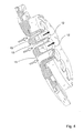
Figure 4 is a further partially-sectioned, perspective view of the invention. - With reference to the drawings mentioned, an example of a fluid-mechanical machine according to the invention, generally indicated 1, is constructed as an operative machine and is designed, in particular, as a centrifugal fan arranged for processing an aeriform fluid. A typical application may be that of a centrifugal fan for the pre-mixing of an air-gas mixture to be supplied to a gas burner which is arranged downstream of the fan with respect to the direction of the flow.
- The fan comprises a
bladed rotor 2 with a rotor-housing manifold 3 in which anintake section 4 and adelivery section 5 of the fan are formed. - The
rotor 2 can be rotated about a rotation axis X by a drive means (not shown), for example, an electric motor onto the drive shaft of which the rotor is keyed. - The
intake section 4 is provided in the region of the axis X and comprises an opening 4a coaxial with the axis X. Thedelivery section 5, on the other hand, is defined in the region of a circumferential profile located downstream of the outside diameter of the rotor and can be approximated to a cylindrical lateral surface the circular base of which is defined by the above-mentioned circumferential profile. - According to the invention, the fan unit contains first diverter means, indicated 10, for diverting the fluid that is delivered through the
delivery section 5 of the fan and second, separate and distinct diverter means, indicated 11, for diverting the flow of operative fluid drawn in from outside the fan towards theintake section 4. - Moreover, the diverter means 10, 11 are selected to have an extent and shape such that the flow at the
delivery section 5 of the fan crosses the flow of fluid directed towards theintake section 4, as shown schematically inFigure 3 , in which the flows are directed separately and distinctly from one another by the first and second diverter means. - In
Figure 3 , the directions of the above-mentioned flows, which cross in a region indicated M, are marked by white-filled arrows (intake flow) and by black arrows (delivery flow), respectively. - More particularly, the first diverter means 10 comprise a respective plurality of ducts, all indicated 12, which extend in the region of the
delivery section 5 of the fan, beyond the outside diameter of therotor 2, to connect the delivery section with the area outside the fan. - The
ducts 12 are distributed circumferentially, downstream of thedelivery section 5, at preselected angular intervals, in particular at regular angular intervals. Moreover, eachduct 12 has, at one of its ends with respect to the direction of the flow, an inlet opening 12a for the fluid (supplied by the delivery section of the fan) in which the flow has a predominant radial component, and an output opening 12b at the opposite end, in which the flow has a predominant axial component. - The second diverter means 11 in turn comprise a respective plurality of ducts, all indicated 13, which are positioned alternately with the
ducts 12 so that, in the region M in which the flows cross, aduct 13 is interposed between a pair ofadjacent ducts 12. - Moreover, with respect to the direction of the flow, each
duct 13 has an inlet opening 13a which is open to the area outside the fan for the admission of the fluid thereto, and an opposed outlet opening 13b communicating with achamber 15 which in turn is connected to theintake section 4 of the fan. Stator blades, indicated 20, are also formed in thechamber 15 for suitably diverting the flow of the operative fluid towards theintake section 4; optionally, thestator blades 20 can impart to the flow a pre-rotation component which is produced by the curved profiles of the stator blades. - The
ducts 13 are also preferably distributed along a circumferential profile which is concentric with the rotor axis and is located downstream of thedelivery section 5. Moreover, a distribution of ducts at regular angular intervals is preferred. The inlet opening 13a of each duct is such as to impart a predominant axial component to the flow which is subsequently deflected to reach the outlet opening 13b where it has a predominant radial component at the inlet to thechamber 15, through which it is conveyed to theintake section 4 of the fan. Theintake section 4 advantageously comprises theopening 4a which is coaxial with the rotor axis X. -
Figure 1 shows a preferred configuration ofducts 13 of which theopenings 13a for the admission of the fluid to the fan are visible. - One of the main advantages of the invention lies in the fact that, the provision of diverter means in the fan for bringing about crossing of the intake and delivery flows permits further processing of the flow output from the fan, improving the efficiency thereof, that is, improving the fluid-mechanical characteristics prior to the supply of the flow to further operative stages of the preselected application. For example, the delivery flow can be cooled by virtue of the cross-over with the intake flow owing to the respective heat-exchange, which is particularly advantageous in air-air pre-heating devices.
- Another advantage is that of improving the operative conditions at the intake in terms of a quieter flow by virtue of the presence of the stator flow-straightener device arranged upstream of the intake section.
- Another advantage lies in the fact that, in a fluid-mechanical machine according to the invention, a flow-rate measurement can be obtained by providing a pressure sensor in the intake chamber.
- Another advantage is that further possible silencing can be achieved by the provision of sound-absorbent material on the walls of the intake chamber.
- Yet another advantage is connected with the greater compactness that can be achieved by the invention in comparison with machines with similar performance characteristics.
- A further advantage lies in a lower cost in comparison with known solutions since the invention incorporates within it several functions for each component. The invention thus achieves the objects proposed, affording the above-mentioned advantages over known solutions.
Claims (6)
- A fluid-mechanical machine comprising a bladed rotor (2) which can be rotated about a rotation axis (X) and which can be housed in a manifold (3) in which an inlet section (4) and a delivery section (5) are defined for the operative fluid processed by the machine, said machine further comprising first and second diverter means (10, 11) for diverting the flow at the inlet to the machine and the flow supplied at the output of the machine, respectively, the first and second diverter means (10, 11) having an extent and shape such that the flow of the fluid at the output of the machine crosses the flow of fluid directed towards the inlet section of the machine, the flows being directed separately and distinctly from one another by the first and second diverter means, characterized in that- the inlet section (4) comprises an axial intake section extending in the region of the rotation axis of the rotor, in that- the delivery section (5) is a radial delivery section, and in that- the first and second diverter means (10, 11) comprise, respectively, a first plurality of ducts (12) and a second plurality of ducts (13) which are arranged alternately so that, in the region (M) in which the flows cross, a duct of one of the pluralities is interposed between a pair of ducts of the other plurality, the ducts (12) of the first plurality being defined in a stator flow-straightener device in which the corresponding ducts are in flow communication with a chamber connecting the ducts to the intake section (4) and the ducts (13) of the second plurality put the delivery section into communication with a common output section extending downstream of the region of crossed flows.
- A fluid-mechanical machine according to Claim 1, characterized in that it is a centrifugal machine.
- A machine according to Claim 1 or Claim 2, characterized in that it is an operative centrifugal machine.
- A machine according to Claim 3, characterized in that it is a fan.
- A machine according to Claim 1, in which the ducts (13) of the second plurality are distributed along a circumferential profile which is concentric with the rotor axis (X) and is located downstream of the delivery section (5), with respect to the direction of the flow.
- A machine according to Claim 5 in which the ducts (13) of the second plurality are arranged at regular angular intervals along the circumferential profile.
Priority Applications (1)
| Application Number | Priority Date | Filing Date | Title |
|---|---|---|---|
| PL08862665T PL2235378T3 (en) | 2007-12-19 | 2008-12-12 | A fluid-mechanical machine, in particular a centrifugal fan |
Applications Claiming Priority (2)
| Application Number | Priority Date | Filing Date | Title |
|---|---|---|---|
| IT000416A ITPD20070416A1 (en) | 2007-12-19 | 2007-12-19 | FLUID DYNAMIC MACHINE, IN PARTICULAR FAN OF CENTRIFUGAL TYPE |
| PCT/EP2008/067434 WO2009077455A1 (en) | 2007-12-19 | 2008-12-12 | A fluid-mechanical machine, in particular a centrifugal fan |
Publications (2)
| Publication Number | Publication Date |
|---|---|
| EP2235378A1 EP2235378A1 (en) | 2010-10-06 |
| EP2235378B1 true EP2235378B1 (en) | 2011-05-18 |
Family
ID=40315750
Family Applications (1)
| Application Number | Title | Priority Date | Filing Date |
|---|---|---|---|
| EP08862665A Active EP2235378B1 (en) | 2007-12-19 | 2008-12-12 | A fluid-mechanical machine, in particular a centrifugal fan |
Country Status (6)
| Country | Link |
|---|---|
| EP (1) | EP2235378B1 (en) |
| AT (1) | ATE510132T1 (en) |
| IT (1) | ITPD20070416A1 (en) |
| PL (1) | PL2235378T3 (en) |
| PT (1) | PT2235378E (en) |
| WO (1) | WO2009077455A1 (en) |
Families Citing this family (2)
| Publication number | Priority date | Publication date | Assignee | Title |
|---|---|---|---|---|
| IT1391676B1 (en) * | 2008-11-07 | 2012-01-17 | Sit La Precisa Spa Con Socio Unico | GAS BURNER UNIT WITH PRE-MIXING |
| RU2397374C1 (en) * | 2009-03-24 | 2010-08-20 | Федеральное государственное унитарное предприятие "Государственный космический научно-производственный центр имени М.В. Хруничева" (ФГУП "ГКНПЦ им. М.В. Хруничева") | Inlet device of negative displacement pump |
Family Cites Families (4)
| Publication number | Priority date | Publication date | Assignee | Title |
|---|---|---|---|---|
| US3289695A (en) | 1964-11-16 | 1966-12-06 | Waterous Co | Centrifugal pump transfer valve |
| FR2039477A5 (en) * | 1969-04-04 | 1971-01-15 | Alsthom | |
| BE865619A (en) | 1978-04-03 | 1978-10-03 | Acec | IMPROVEMENTS TO CENTRIFUGAL PUMPS IN DOUBLE WHEEL TANK |
| DE3842826C2 (en) | 1988-12-20 | 1997-01-23 | Klein Schanzlin & Becker Ag | Centrifugal pump with double-flow suction stage |
-
2007
- 2007-12-19 IT IT000416A patent/ITPD20070416A1/en unknown
-
2008
- 2008-12-12 EP EP08862665A patent/EP2235378B1/en active Active
- 2008-12-12 AT AT08862665T patent/ATE510132T1/en not_active IP Right Cessation
- 2008-12-12 PL PL08862665T patent/PL2235378T3/en unknown
- 2008-12-12 WO PCT/EP2008/067434 patent/WO2009077455A1/en not_active Ceased
- 2008-12-12 PT PT08862665T patent/PT2235378E/en unknown
Also Published As
| Publication number | Publication date |
|---|---|
| ITPD20070416A1 (en) | 2009-06-20 |
| WO2009077455A1 (en) | 2009-06-25 |
| EP2235378A1 (en) | 2010-10-06 |
| PT2235378E (en) | 2011-08-25 |
| ATE510132T1 (en) | 2011-06-15 |
| PL2235378T3 (en) | 2011-12-30 |
Similar Documents
| Publication | Publication Date | Title |
|---|---|---|
| CN209959503U (en) | Diagonal fan | |
| KR100984445B1 (en) | Centrifugal compressor | |
| CN101868629B (en) | Compressor | |
| CN103717905B (en) | Side channel blower having a plurality of feed channels distributed over the circumference | |
| US20170023001A1 (en) | Centrifugal fan | |
| JP4659389B2 (en) | Centrifugal blower | |
| EP2235378A1 (en) | A fluid-mechanical machine, in particular a centrifugal fan | |
| ATE252688T1 (en) | ARRANGEMENT OF A MULTI-STAGE HEAT PUMP SYSTEM | |
| WO2017094064A1 (en) | Multi-stage centrifugal compressor | |
| KR101607502B1 (en) | Centrifugal pump | |
| JP2010236401A (en) | Centrifugal fluid machine | |
| US11965514B2 (en) | Axial and downstream compressor assembly | |
| US11499569B2 (en) | Mixed-flow compressor with counter-rotating diffuser | |
| RU2003134011A (en) | EXHAUST FAN | |
| WO2024241824A1 (en) | Uniaxial multistage centrifugal fluid machine | |
| WO2009077426A1 (en) | A centrifugal fan | |
| EP1624191A1 (en) | Side channel blower | |
| JP6258237B2 (en) | Centrifugal compressor | |
| KR20150137483A (en) | Centrifugal impeller having backward airfoil suction surface type | |
| CN210033892U (en) | Diagonal fan | |
| MY153165A (en) | Multi-vane fans for automotive air conditioning apparatus | |
| EP2235442B1 (en) | Fan unit for gas-burners with pre-mixing and burner apparatus including said fan | |
| CN107165866B (en) | Reflux device and compressor with same | |
| KR100487378B1 (en) | Spiral Fan Assembly | |
| JP7434220B2 (en) | Axial compressor and diffuser for axial compressor |
Legal Events
| Date | Code | Title | Description |
|---|---|---|---|
| PUAI | Public reference made under article 153(3) epc to a published international application that has entered the european phase |
Free format text: ORIGINAL CODE: 0009012 |
|
| 17P | Request for examination filed |
Effective date: 20100715 |
|
| AK | Designated contracting states |
Kind code of ref document: A1 Designated state(s): AT BE BG CH CY CZ DE DK EE ES FI FR GB GR HR HU IE IS IT LI LT LU LV MC MT NL NO PL PT RO SE SI SK TR |
|
| AX | Request for extension of the european patent |
Extension state: AL BA MK RS |
|
| GRAP | Despatch of communication of intention to grant a patent |
Free format text: ORIGINAL CODE: EPIDOSNIGR1 |
|
| DAX | Request for extension of the european patent (deleted) | ||
| GRAS | Grant fee paid |
Free format text: ORIGINAL CODE: EPIDOSNIGR3 |
|
| GRAA | (expected) grant |
Free format text: ORIGINAL CODE: 0009210 |
|
| REG | Reference to a national code |
Ref country code: GB Ref legal event code: FG4D |
|
| REG | Reference to a national code |
Ref country code: CH Ref legal event code: EP |
|
| REG | Reference to a national code |
Ref country code: IE Ref legal event code: FG4D |
|
| REG | Reference to a national code |
Ref country code: DE Ref legal event code: R096 Ref document number: 602008007116 Country of ref document: DE Effective date: 20110630 |
|
| REG | Reference to a national code |
Ref country code: NL Ref legal event code: T3 |
|
| REG | Reference to a national code |
Ref country code: PT Ref legal event code: SC4A Free format text: AVAILABILITY OF NATIONAL TRANSLATION Effective date: 20110811 |
|
| PG25 | Lapsed in a contracting state [announced via postgrant information from national office to epo] |
Ref country code: NO Free format text: LAPSE BECAUSE OF FAILURE TO SUBMIT A TRANSLATION OF THE DESCRIPTION OR TO PAY THE FEE WITHIN THE PRESCRIBED TIME-LIMIT Effective date: 20110818 Ref country code: LT Free format text: LAPSE BECAUSE OF FAILURE TO SUBMIT A TRANSLATION OF THE DESCRIPTION OR TO PAY THE FEE WITHIN THE PRESCRIBED TIME-LIMIT Effective date: 20110518 Ref country code: SE Free format text: LAPSE BECAUSE OF FAILURE TO SUBMIT A TRANSLATION OF THE DESCRIPTION OR TO PAY THE FEE WITHIN THE PRESCRIBED TIME-LIMIT Effective date: 20110518 Ref country code: HR Free format text: LAPSE BECAUSE OF FAILURE TO SUBMIT A TRANSLATION OF THE DESCRIPTION OR TO PAY THE FEE WITHIN THE PRESCRIBED TIME-LIMIT Effective date: 20110518 |
|
| PG25 | Lapsed in a contracting state [announced via postgrant information from national office to epo] |
Ref country code: IS Free format text: LAPSE BECAUSE OF FAILURE TO SUBMIT A TRANSLATION OF THE DESCRIPTION OR TO PAY THE FEE WITHIN THE PRESCRIBED TIME-LIMIT Effective date: 20110918 Ref country code: LV Free format text: LAPSE BECAUSE OF FAILURE TO SUBMIT A TRANSLATION OF THE DESCRIPTION OR TO PAY THE FEE WITHIN THE PRESCRIBED TIME-LIMIT Effective date: 20110518 Ref country code: FI Free format text: LAPSE BECAUSE OF FAILURE TO SUBMIT A TRANSLATION OF THE DESCRIPTION OR TO PAY THE FEE WITHIN THE PRESCRIBED TIME-LIMIT Effective date: 20110518 Ref country code: GR Free format text: LAPSE BECAUSE OF FAILURE TO SUBMIT A TRANSLATION OF THE DESCRIPTION OR TO PAY THE FEE WITHIN THE PRESCRIBED TIME-LIMIT Effective date: 20110819 Ref country code: CY Free format text: LAPSE BECAUSE OF FAILURE TO SUBMIT A TRANSLATION OF THE DESCRIPTION OR TO PAY THE FEE WITHIN THE PRESCRIBED TIME-LIMIT Effective date: 20110518 Ref country code: AT Free format text: LAPSE BECAUSE OF FAILURE TO SUBMIT A TRANSLATION OF THE DESCRIPTION OR TO PAY THE FEE WITHIN THE PRESCRIBED TIME-LIMIT Effective date: 20110518 Ref country code: BE Free format text: LAPSE BECAUSE OF FAILURE TO SUBMIT A TRANSLATION OF THE DESCRIPTION OR TO PAY THE FEE WITHIN THE PRESCRIBED TIME-LIMIT Effective date: 20110518 Ref country code: SI Free format text: LAPSE BECAUSE OF FAILURE TO SUBMIT A TRANSLATION OF THE DESCRIPTION OR TO PAY THE FEE WITHIN THE PRESCRIBED TIME-LIMIT Effective date: 20110518 Ref country code: ES Free format text: LAPSE BECAUSE OF FAILURE TO SUBMIT A TRANSLATION OF THE DESCRIPTION OR TO PAY THE FEE WITHIN THE PRESCRIBED TIME-LIMIT Effective date: 20110829 |
|
| REG | Reference to a national code |
Ref country code: PL Ref legal event code: T3 |
|
| PG25 | Lapsed in a contracting state [announced via postgrant information from national office to epo] |
Ref country code: EE Free format text: LAPSE BECAUSE OF FAILURE TO SUBMIT A TRANSLATION OF THE DESCRIPTION OR TO PAY THE FEE WITHIN THE PRESCRIBED TIME-LIMIT Effective date: 20110518 |
|
| PG25 | Lapsed in a contracting state [announced via postgrant information from national office to epo] |
Ref country code: SK Free format text: LAPSE BECAUSE OF FAILURE TO SUBMIT A TRANSLATION OF THE DESCRIPTION OR TO PAY THE FEE WITHIN THE PRESCRIBED TIME-LIMIT Effective date: 20110518 Ref country code: RO Free format text: LAPSE BECAUSE OF FAILURE TO SUBMIT A TRANSLATION OF THE DESCRIPTION OR TO PAY THE FEE WITHIN THE PRESCRIBED TIME-LIMIT Effective date: 20110518 Ref country code: DK Free format text: LAPSE BECAUSE OF FAILURE TO SUBMIT A TRANSLATION OF THE DESCRIPTION OR TO PAY THE FEE WITHIN THE PRESCRIBED TIME-LIMIT Effective date: 20110518 |
|
| PLBE | No opposition filed within time limit |
Free format text: ORIGINAL CODE: 0009261 |
|
| STAA | Information on the status of an ep patent application or granted ep patent |
Free format text: STATUS: NO OPPOSITION FILED WITHIN TIME LIMIT |
|
| 26N | No opposition filed |
Effective date: 20120221 |
|
| REG | Reference to a national code |
Ref country code: DE Ref legal event code: R097 Ref document number: 602008007116 Country of ref document: DE Effective date: 20120221 |
|
| PG25 | Lapsed in a contracting state [announced via postgrant information from national office to epo] |
Ref country code: MC Free format text: LAPSE BECAUSE OF NON-PAYMENT OF DUE FEES Effective date: 20111231 |
|
| REG | Reference to a national code |
Ref country code: IE Ref legal event code: MM4A |
|
| PG25 | Lapsed in a contracting state [announced via postgrant information from national office to epo] |
Ref country code: IE Free format text: LAPSE BECAUSE OF NON-PAYMENT OF DUE FEES Effective date: 20111212 |
|
| PG25 | Lapsed in a contracting state [announced via postgrant information from national office to epo] |
Ref country code: MT Free format text: LAPSE BECAUSE OF FAILURE TO SUBMIT A TRANSLATION OF THE DESCRIPTION OR TO PAY THE FEE WITHIN THE PRESCRIBED TIME-LIMIT Effective date: 20110518 |
|
| PG25 | Lapsed in a contracting state [announced via postgrant information from national office to epo] |
Ref country code: LU Free format text: LAPSE BECAUSE OF NON-PAYMENT OF DUE FEES Effective date: 20111212 |
|
| PG25 | Lapsed in a contracting state [announced via postgrant information from national office to epo] |
Ref country code: BG Free format text: LAPSE BECAUSE OF FAILURE TO SUBMIT A TRANSLATION OF THE DESCRIPTION OR TO PAY THE FEE WITHIN THE PRESCRIBED TIME-LIMIT Effective date: 20110818 |
|
| REG | Reference to a national code |
Ref country code: CH Ref legal event code: PL |
|
| PG25 | Lapsed in a contracting state [announced via postgrant information from national office to epo] |
Ref country code: CH Free format text: LAPSE BECAUSE OF NON-PAYMENT OF DUE FEES Effective date: 20121231 Ref country code: LI Free format text: LAPSE BECAUSE OF NON-PAYMENT OF DUE FEES Effective date: 20121231 Ref country code: HU Free format text: LAPSE BECAUSE OF FAILURE TO SUBMIT A TRANSLATION OF THE DESCRIPTION OR TO PAY THE FEE WITHIN THE PRESCRIBED TIME-LIMIT Effective date: 20110518 |
|
| REG | Reference to a national code |
Ref country code: DE Ref legal event code: R082 Ref document number: 602008007116 Country of ref document: DE Representative=s name: DREISS PATENTANWAELTE PARTG MBB, DE |
|
| REG | Reference to a national code |
Ref country code: GB Ref legal event code: 732E Free format text: REGISTERED BETWEEN 20150122 AND 20150128 |
|
| REG | Reference to a national code |
Ref country code: PT Ref legal event code: PC4A Owner name: SIT S.P.A., IT Effective date: 20150122 |
|
| REG | Reference to a national code |
Ref country code: DE Ref legal event code: R082 Ref document number: 602008007116 Country of ref document: DE Representative=s name: DREISS PATENTANWAELTE PARTG MBB, DE Effective date: 20150213 Ref country code: DE Ref legal event code: R081 Ref document number: 602008007116 Country of ref document: DE Owner name: SIT S.P.A., IT Free format text: FORMER OWNER: LN 2 S.R.L. A SOCIO UNICO, 62010 MONTECASSIANO, IT Effective date: 20150213 |
|
| REG | Reference to a national code |
Ref country code: FR Ref legal event code: GC Effective date: 20150223 Ref country code: FR Ref legal event code: TP Owner name: SIT S.P.A., IT Effective date: 20150223 |
|
| REG | Reference to a national code |
Ref country code: NL Ref legal event code: SD Effective date: 20150602 Ref country code: NL Ref legal event code: TD Effective date: 20150602 |
|
| REG | Reference to a national code |
Ref country code: FR Ref legal event code: PLFP Year of fee payment: 8 |
|
| REG | Reference to a national code |
Ref country code: FR Ref legal event code: PLFP Year of fee payment: 9 |
|
| REG | Reference to a national code |
Ref country code: NL Ref legal event code: RF Free format text: RIGHT OF PLEDGE, REMOVED Effective date: 20171121 |
|
| REG | Reference to a national code |
Ref country code: FR Ref legal event code: PLFP Year of fee payment: 10 |
|
| REG | Reference to a national code |
Ref country code: FR Ref legal event code: RG Effective date: 20180202 |
|
| PGFP | Annual fee paid to national office [announced via postgrant information from national office to epo] |
Ref country code: PT Payment date: 20191121 Year of fee payment: 12 Ref country code: CZ Payment date: 20191210 Year of fee payment: 12 |
|
| PGFP | Annual fee paid to national office [announced via postgrant information from national office to epo] |
Ref country code: PL Payment date: 20191122 Year of fee payment: 12 |
|
| PGFP | Annual fee paid to national office [announced via postgrant information from national office to epo] |
Ref country code: GB Payment date: 20201223 Year of fee payment: 13 Ref country code: FR Payment date: 20201223 Year of fee payment: 13 |
|
| PG25 | Lapsed in a contracting state [announced via postgrant information from national office to epo] |
Ref country code: PT Free format text: LAPSE BECAUSE OF NON-PAYMENT OF DUE FEES Effective date: 20210614 Ref country code: CZ Free format text: LAPSE BECAUSE OF NON-PAYMENT OF DUE FEES Effective date: 20201212 |
|
| PGFP | Annual fee paid to national office [announced via postgrant information from national office to epo] |
Ref country code: DE Payment date: 20211210 Year of fee payment: 14 |
|
| PGFP | Annual fee paid to national office [announced via postgrant information from national office to epo] |
Ref country code: IT Payment date: 20211119 Year of fee payment: 14 |
|
| PGFP | Annual fee paid to national office [announced via postgrant information from national office to epo] |
Ref country code: NL Payment date: 20211221 Year of fee payment: 14 |
|
| GBPC | Gb: european patent ceased through non-payment of renewal fee |
Effective date: 20211212 |
|
| PG25 | Lapsed in a contracting state [announced via postgrant information from national office to epo] |
Ref country code: GB Free format text: LAPSE BECAUSE OF NON-PAYMENT OF DUE FEES Effective date: 20211212 |
|
| PG25 | Lapsed in a contracting state [announced via postgrant information from national office to epo] |
Ref country code: PL Free format text: LAPSE BECAUSE OF NON-PAYMENT OF DUE FEES Effective date: 20201212 Ref country code: FR Free format text: LAPSE BECAUSE OF NON-PAYMENT OF DUE FEES Effective date: 20211231 |
|
| REG | Reference to a national code |
Ref country code: DE Ref legal event code: R119 Ref document number: 602008007116 Country of ref document: DE |
|
| REG | Reference to a national code |
Ref country code: NL Ref legal event code: MM Effective date: 20230101 |
|
| PG25 | Lapsed in a contracting state [announced via postgrant information from national office to epo] |
Ref country code: NL Free format text: LAPSE BECAUSE OF NON-PAYMENT OF DUE FEES Effective date: 20230101 |
|
| PG25 | Lapsed in a contracting state [announced via postgrant information from national office to epo] |
Ref country code: DE Free format text: LAPSE BECAUSE OF NON-PAYMENT OF DUE FEES Effective date: 20230701 |
|
| PG25 | Lapsed in a contracting state [announced via postgrant information from national office to epo] |
Ref country code: IT Free format text: LAPSE BECAUSE OF NON-PAYMENT OF DUE FEES Effective date: 20221212 |
|
| PGFP | Annual fee paid to national office [announced via postgrant information from national office to epo] |
Ref country code: TR Payment date: 20231211 Year of fee payment: 16 |