EP2235081B1 - Block polymer - Google Patents
Block polymer Download PDFInfo
- Publication number
- EP2235081B1 EP2235081B1 EP08870864A EP08870864A EP2235081B1 EP 2235081 B1 EP2235081 B1 EP 2235081B1 EP 08870864 A EP08870864 A EP 08870864A EP 08870864 A EP08870864 A EP 08870864A EP 2235081 B1 EP2235081 B1 EP 2235081B1
- Authority
- EP
- European Patent Office
- Prior art keywords
- block
- transporting
- polymer
- electron
- block polymer
- Prior art date
- Legal status (The legal status is an assumption and is not a legal conclusion. Google has not performed a legal analysis and makes no representation as to the accuracy of the status listed.)
- Not-in-force
Links
- 229920000642 polymer Polymers 0.000 title claims abstract description 59
- HSFWRNGVRCDJHI-UHFFFAOYSA-N alpha-acetylene Natural products C#C HSFWRNGVRCDJHI-UHFFFAOYSA-N 0.000 claims abstract description 23
- 229920001197 polyacetylene Polymers 0.000 claims abstract description 22
- YXFVVABEGXRONW-UHFFFAOYSA-N Toluene Chemical compound CC1=CC=CC=C1 YXFVVABEGXRONW-UHFFFAOYSA-N 0.000 description 30
- 125000000524 functional group Chemical group 0.000 description 14
- 239000000463 material Substances 0.000 description 13
- 239000000758 substrate Substances 0.000 description 9
- 239000000243 solution Substances 0.000 description 8
- XLYOFNOQVPJJNP-UHFFFAOYSA-N water Substances O XLYOFNOQVPJJNP-UHFFFAOYSA-N 0.000 description 8
- IJGRMHOSHXDMSA-UHFFFAOYSA-N Atomic nitrogen Chemical compound N#N IJGRMHOSHXDMSA-UHFFFAOYSA-N 0.000 description 7
- 239000010410 layer Substances 0.000 description 7
- 239000000178 monomer Substances 0.000 description 7
- 238000006116 polymerization reaction Methods 0.000 description 7
- PBEXVWXHXPEARD-UHFFFAOYSA-N 1-ethynyl-2,3,4,5,6-pentafluorobenzene Chemical group FC1=C(F)C(F)=C(C#C)C(F)=C1F PBEXVWXHXPEARD-UHFFFAOYSA-N 0.000 description 6
- OKKJLVBELUTLKV-UHFFFAOYSA-N Methanol Chemical compound OC OKKJLVBELUTLKV-UHFFFAOYSA-N 0.000 description 6
- 238000000034 method Methods 0.000 description 6
- 230000008569 process Effects 0.000 description 6
- ASBDHAOKWPWQMZ-UHFFFAOYSA-N 3-ethynylquinoline Chemical compound C1=CC=CC2=CC(C#C)=CN=C21 ASBDHAOKWPWQMZ-UHFFFAOYSA-N 0.000 description 5
- 125000000217 alkyl group Chemical group 0.000 description 5
- 125000003118 aryl group Chemical group 0.000 description 5
- 230000006870 function Effects 0.000 description 5
- QDYFCLVSLUZDHB-UHFFFAOYSA-N 4-ethynyl-n,n-diphenylaniline Chemical group C1=CC(C#C)=CC=C1N(C=1C=CC=CC=1)C1=CC=CC=C1 QDYFCLVSLUZDHB-UHFFFAOYSA-N 0.000 description 4
- 230000015572 biosynthetic process Effects 0.000 description 4
- 238000006243 chemical reaction Methods 0.000 description 4
- 238000005868 electrolysis reaction Methods 0.000 description 4
- 239000011259 mixed solution Substances 0.000 description 4
- 229910052757 nitrogen Inorganic materials 0.000 description 4
- 238000003786 synthesis reaction Methods 0.000 description 4
- ZMANZCXQSJIPKH-UHFFFAOYSA-N Triethylamine Chemical compound CCN(CC)CC ZMANZCXQSJIPKH-UHFFFAOYSA-N 0.000 description 3
- 125000002534 ethynyl group Chemical group [H]C#C* 0.000 description 3
- 238000004519 manufacturing process Methods 0.000 description 3
- 238000005442 molecular electronic Methods 0.000 description 3
- 230000006798 recombination Effects 0.000 description 3
- 238000005215 recombination Methods 0.000 description 3
- 125000001424 substituent group Chemical group 0.000 description 3
- -1 triazole derivatives Chemical class 0.000 description 3
- 229910021642 ultra pure water Inorganic materials 0.000 description 3
- 239000012498 ultrapure water Substances 0.000 description 3
- CFNMUZCFSDMZPQ-GHXNOFRVSA-N 7-[(z)-3-methyl-4-(4-methyl-5-oxo-2h-furan-2-yl)but-2-enoxy]chromen-2-one Chemical compound C=1C=C2C=CC(=O)OC2=CC=1OC/C=C(/C)CC1OC(=O)C(C)=C1 CFNMUZCFSDMZPQ-GHXNOFRVSA-N 0.000 description 2
- JJIQKIUIIVFHAN-UHFFFAOYSA-N 9-(4-ethynylphenyl)carbazole Chemical group C1=CC(C#C)=CC=C1N1C2=CC=CC=C2C2=CC=CC=C21 JJIQKIUIIVFHAN-UHFFFAOYSA-N 0.000 description 2
- QGZKDVFQNNGYKY-UHFFFAOYSA-N Ammonia Chemical compound N QGZKDVFQNNGYKY-UHFFFAOYSA-N 0.000 description 2
- OKTJSMMVPCPJKN-UHFFFAOYSA-N Carbon Chemical group [C] OKTJSMMVPCPJKN-UHFFFAOYSA-N 0.000 description 2
- HEDRZPFGACZZDS-UHFFFAOYSA-N Chloroform Chemical compound ClC(Cl)Cl HEDRZPFGACZZDS-UHFFFAOYSA-N 0.000 description 2
- LFQSCWFLJHTTHZ-UHFFFAOYSA-N Ethanol Chemical compound CCO LFQSCWFLJHTTHZ-UHFFFAOYSA-N 0.000 description 2
- MHAJPDPJQMAIIY-UHFFFAOYSA-N Hydrogen peroxide Chemical compound OO MHAJPDPJQMAIIY-UHFFFAOYSA-N 0.000 description 2
- QIELHOOPLIAKEO-UHFFFAOYSA-K [Cl-].C12=CC=C(CC1)C2.[Rh+3].[Cl-].[Cl-] Chemical compound [Cl-].C12=CC=C(CC1)C2.[Rh+3].[Cl-].[Cl-] QIELHOOPLIAKEO-UHFFFAOYSA-K 0.000 description 2
- 239000007864 aqueous solution Substances 0.000 description 2
- 230000004888 barrier function Effects 0.000 description 2
- 230000008901 benefit Effects 0.000 description 2
- 150000001716 carbazoles Chemical class 0.000 description 2
- 150000001875 compounds Chemical class 0.000 description 2
- 229920000547 conjugated polymer Polymers 0.000 description 2
- 238000010276 construction Methods 0.000 description 2
- 238000011161 development Methods 0.000 description 2
- 230000018109 developmental process Effects 0.000 description 2
- 239000000539 dimer Substances 0.000 description 2
- 238000001914 filtration Methods 0.000 description 2
- 238000005227 gel permeation chromatography Methods 0.000 description 2
- 239000011521 glass Substances 0.000 description 2
- 229920001519 homopolymer Polymers 0.000 description 2
- 230000000977 initiatory effect Effects 0.000 description 2
- 239000002346 layers by function Substances 0.000 description 2
- 238000002360 preparation method Methods 0.000 description 2
- 238000010926 purge Methods 0.000 description 2
- 150000003248 quinolines Chemical class 0.000 description 2
- 230000009467 reduction Effects 0.000 description 2
- 229910052703 rhodium Inorganic materials 0.000 description 2
- 239000010948 rhodium Substances 0.000 description 2
- MHOVAHRLVXNVSD-UHFFFAOYSA-N rhodium atom Chemical compound [Rh] MHOVAHRLVXNVSD-UHFFFAOYSA-N 0.000 description 2
- 239000002904 solvent Substances 0.000 description 2
- 238000012360 testing method Methods 0.000 description 2
- 238000012546 transfer Methods 0.000 description 2
- RIOQSEWOXXDEQQ-UHFFFAOYSA-N triphenylphosphine Chemical compound C1=CC=CC=C1P(C=1C=CC=CC=1)C1=CC=CC=C1 RIOQSEWOXXDEQQ-UHFFFAOYSA-N 0.000 description 2
- 238000005160 1H NMR spectroscopy Methods 0.000 description 1
- DDTHMESPCBONDT-UHFFFAOYSA-N 4-(4-oxocyclohexa-2,5-dien-1-ylidene)cyclohexa-2,5-dien-1-one Chemical class C1=CC(=O)C=CC1=C1C=CC(=O)C=C1 DDTHMESPCBONDT-UHFFFAOYSA-N 0.000 description 1
- ZAZGCFIWMBUKDD-UHFFFAOYSA-N 7-ethyl-1-(3-ethynylhexyl)-9h-carbazole Chemical compound N1C2=CC(CC)=CC=C2C2=C1C(CCC(CCC)C#C)=CC=C2 ZAZGCFIWMBUKDD-UHFFFAOYSA-N 0.000 description 1
- NZGXEUWGGSDALJ-UHFFFAOYSA-N C1=CC=CC=C1C1=NC=CC=C1[Ir](C=1C(=NC=CC=1)C=1C=CC=CC=1)C1=CC=CN=C1C1=CC=CC=C1 Chemical compound C1=CC=CC=C1C1=NC=CC=C1[Ir](C=1C(=NC=CC=1)C=1C=CC=CC=1)C1=CC=CN=C1C1=CC=CC=C1 NZGXEUWGGSDALJ-UHFFFAOYSA-N 0.000 description 1
- 239000007983 Tris buffer Substances 0.000 description 1
- 238000010521 absorption reaction Methods 0.000 description 1
- 229910052782 aluminium Inorganic materials 0.000 description 1
- 125000003368 amide group Chemical group 0.000 description 1
- 229910021529 ammonia Inorganic materials 0.000 description 1
- 229940027991 antiseptic and disinfectant quinoline derivative Drugs 0.000 description 1
- 150000004982 aromatic amines Chemical class 0.000 description 1
- 150000004696 coordination complex Chemical class 0.000 description 1
- 238000013461 design Methods 0.000 description 1
- 229910001873 dinitrogen Inorganic materials 0.000 description 1
- 239000012776 electronic material Substances 0.000 description 1
- VXAWCKIQYKXJMD-UHFFFAOYSA-N ethynamine Chemical group NC#C VXAWCKIQYKXJMD-UHFFFAOYSA-N 0.000 description 1
- 230000005284 excitation Effects 0.000 description 1
- 230000001747 exhibiting effect Effects 0.000 description 1
- 230000002349 favourable effect Effects 0.000 description 1
- 150000008376 fluorenones Chemical class 0.000 description 1
- 125000003983 fluorenyl group Chemical class C1(=CC=CC=2C3=CC=CC=C3CC12)* 0.000 description 1
- PCHJSUWPFVWCPO-UHFFFAOYSA-N gold Chemical compound [Au] PCHJSUWPFVWCPO-UHFFFAOYSA-N 0.000 description 1
- 239000010931 gold Substances 0.000 description 1
- 229910052737 gold Inorganic materials 0.000 description 1
- 230000005525 hole transport Effects 0.000 description 1
- 239000001257 hydrogen Substances 0.000 description 1
- 229910052739 hydrogen Inorganic materials 0.000 description 1
- 230000005660 hydrophilic surface Effects 0.000 description 1
- 125000002887 hydroxy group Chemical group [H]O* 0.000 description 1
- 150000002460 imidazoles Chemical class 0.000 description 1
- 230000006872 improvement Effects 0.000 description 1
- 238000002347 injection Methods 0.000 description 1
- 239000007924 injection Substances 0.000 description 1
- 229910010272 inorganic material Inorganic materials 0.000 description 1
- 239000011147 inorganic material Substances 0.000 description 1
- 238000011835 investigation Methods 0.000 description 1
- 229910052744 lithium Inorganic materials 0.000 description 1
- 230000007774 longterm Effects 0.000 description 1
- 230000015654 memory Effects 0.000 description 1
- 125000001434 methanylylidene group Chemical group [H]C#[*] 0.000 description 1
- 238000002156 mixing Methods 0.000 description 1
- 125000004433 nitrogen atom Chemical group N* 0.000 description 1
- 239000011368 organic material Substances 0.000 description 1
- 150000004866 oxadiazoles Chemical class 0.000 description 1
- 150000007978 oxazole derivatives Chemical class 0.000 description 1
- NRNFFDZCBYOZJY-UHFFFAOYSA-N p-quinodimethane Chemical class C=C1C=CC(=C)C=C1 NRNFFDZCBYOZJY-UHFFFAOYSA-N 0.000 description 1
- 125000001997 phenyl group Chemical group [H]C1=C([H])C([H])=C(*)C([H])=C1[H] 0.000 description 1
- 150000004986 phenylenediamines Chemical class 0.000 description 1
- IEQIEDJGQAUEQZ-UHFFFAOYSA-N phthalocyanine Chemical class N1C(N=C2C3=CC=CC=C3C(N=C3C4=CC=CC=C4C(=N4)N3)=N2)=C(C=CC=C2)C2=C1N=C1C2=CC=CC=C2C4=N1 IEQIEDJGQAUEQZ-UHFFFAOYSA-N 0.000 description 1
- 229920006254 polymer film Polymers 0.000 description 1
- 230000000379 polymerizing effect Effects 0.000 description 1
- 150000004033 porphyrin derivatives Chemical class 0.000 description 1
- 150000003216 pyrazines Chemical class 0.000 description 1
- 150000003222 pyridines Chemical class 0.000 description 1
- 229940083082 pyrimidine derivative acting on arteriolar smooth muscle Drugs 0.000 description 1
- 150000003230 pyrimidines Chemical class 0.000 description 1
- 230000001105 regulatory effect Effects 0.000 description 1
- 238000011160 research Methods 0.000 description 1
- 239000011347 resin Substances 0.000 description 1
- 229920005989 resin Polymers 0.000 description 1
- 239000011369 resultant mixture Substances 0.000 description 1
- 239000004065 semiconductor Substances 0.000 description 1
- 238000000926 separation method Methods 0.000 description 1
- 230000003595 spectral effect Effects 0.000 description 1
- PJANXHGTPQOBST-UHFFFAOYSA-N stilbene Chemical class C=1C=CC=CC=1C=CC1=CC=CC=C1 PJANXHGTPQOBST-UHFFFAOYSA-N 0.000 description 1
- QAOWNCQODCNURD-UHFFFAOYSA-N sulfuric acid Substances OS(O)(=O)=O QAOWNCQODCNURD-UHFFFAOYSA-N 0.000 description 1
- 229940042055 systemic antimycotics triazole derivative Drugs 0.000 description 1
- 150000003512 tertiary amines Chemical class 0.000 description 1
- FHCPAXDKURNIOZ-UHFFFAOYSA-N tetrathiafulvalene Chemical class S1C=CSC1=C1SC=CS1 FHCPAXDKURNIOZ-UHFFFAOYSA-N 0.000 description 1
- 150000004867 thiadiazoles Chemical class 0.000 description 1
- 150000007979 thiazole derivatives Chemical class 0.000 description 1
- 125000003396 thiol group Chemical group [H]S* 0.000 description 1
- 150000003852 triazoles Chemical class 0.000 description 1
- 125000006617 triphenylamine group Chemical group 0.000 description 1
- 125000000391 vinyl group Chemical group [H]C([*])=C([H])[H] 0.000 description 1
- 229920002554 vinyl polymer Polymers 0.000 description 1
Images


Classifications
-
- C—CHEMISTRY; METALLURGY
- C08—ORGANIC MACROMOLECULAR COMPOUNDS; THEIR PREPARATION OR CHEMICAL WORKING-UP; COMPOSITIONS BASED THEREON
- C08F—MACROMOLECULAR COMPOUNDS OBTAINED BY REACTIONS ONLY INVOLVING CARBON-TO-CARBON UNSATURATED BONDS
- C08F297/00—Macromolecular compounds obtained by successively polymerising different monomer systems using a catalyst of the ionic or coordination type without deactivating the intermediate polymer
-
- H—ELECTRICITY
- H10—SEMICONDUCTOR DEVICES; ELECTRIC SOLID-STATE DEVICES NOT OTHERWISE PROVIDED FOR
- H10K—ORGANIC ELECTRIC SOLID-STATE DEVICES
- H10K85/00—Organic materials used in the body or electrodes of devices covered by this subclass
- H10K85/10—Organic polymers or oligomers
- H10K85/141—Organic polymers or oligomers comprising aliphatic or olefinic chains, e.g. poly N-vinylcarbazol, PVC or PTFE
- H10K85/143—Polyacetylene; Derivatives thereof
-
- H—ELECTRICITY
- H10—SEMICONDUCTOR DEVICES; ELECTRIC SOLID-STATE DEVICES NOT OTHERWISE PROVIDED FOR
- H10K—ORGANIC ELECTRIC SOLID-STATE DEVICES
- H10K50/00—Organic light-emitting devices
- H10K50/10—OLEDs or polymer light-emitting diodes [PLED]
- H10K50/11—OLEDs or polymer light-emitting diodes [PLED] characterised by the electroluminescent [EL] layers
-
- H—ELECTRICITY
- H10—SEMICONDUCTOR DEVICES; ELECTRIC SOLID-STATE DEVICES NOT OTHERWISE PROVIDED FOR
- H10K—ORGANIC ELECTRIC SOLID-STATE DEVICES
- H10K50/00—Organic light-emitting devices
- H10K50/10—OLEDs or polymer light-emitting diodes [PLED]
- H10K50/14—Carrier transporting layers
Definitions
- the present invention relates a novel block polymer.
- the novel block polymer according to the present invention can be applied to a light-emitting layer of a light-emitting device, and a transistor.
- organic electronic devices such as transistors and light-emitting devices using an organic material.
- the organic electronic device has a merit of permitting the device itself to be bent.
- an electronic device using a conjugated polymer can be fabricated from a solution and thus can be fabricated at low cost.
- the device has a merit of permitting its area to be easily enlarged.
- the conjugated polymer permits of realizing highly integrated devices such as monomolecular devices and molecular electronic devices.
- An organic electronic device is generally comprised of a layer device structure with several functional layers stacked on one another, which layers have their respective functions such as electron transport and hole transport.
- the functional layers can be freely combined, whereas a problem arises on injection of electrons or holes due to presence of an interface between layers.
- substituted helical polyacetylene has been proposed as a molecular electronic material of a conjugated system, which is expected to solve the above problems.
- the substituted helical polyacetylene is disclosed in Japanese Patent Application Laid-Open No. 2004-115628 and Japanese Patent Application Laid-Open No. 2004-027182 .
- Polyacetylene having a pseudo-hexagonal structure and a super-helical conjugated structure due to ⁇ electrons based on a double bond is disclosed in Japanese Patent Application Laid-Open No.
- novel block polymers applicable to light-emitting layers of light-emitting devices can be provided, and development of novel devices becomes feasible.
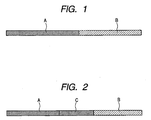
- FIG. 1 illustrates a block polymer according to the present invention.
- the block polymer has a block A described as 'A' and a block B described as 'B'.
- the block B becomes a hole-transporting block when the block A is an electron-transporting block.
- the block B exhibits P-type conductivity.
- the block polymer may be so formed that a block C is sandwiched between the block A and the block B.
- the block C is a luminescent block or a block exhibiting I-type conductivity.
- the backbone of the block polymer is a carbon chain, and it is possible to provide a block polymer having functionality as illustrated in FIG. 1 by using the function of a side chain thereof.
- a polyacetylene backbone that is a carbon chain of a conjugated system is used The functionality is imparted by varying a side chain.
- the backbone becomes a continuous polymer chain, whereby a block polymer having an electron-transporting block and a hole-transporting block can be provided, which means that one having no interface can be provided.
- Such a construction has an advantage that the transport of an electron or a hole is efficiently conducted.
- FIGS. 3 and 4 illustrate cases where the structure of the main chain backbone is of the helical type.
- a main chain 301 is an acetylene backbone and forms a helix.
- An electron-transporting block 302 formed with pentafluorophenylacetylene and a hole- transporting block 303 formed with 4-diphenyl-aminophenylacetylene are formed on side chains of the helical acetylene backbone to provide a block polymer.
- FIG. 4 is a Y-Z plan view of FIG. 3 .
- the plan views of the compound illustrated in FIGS. 3 and 4 are FIG. 5 and FIG. 6 . It is inferred from FIGS.
- the electron-transporting block and the hole-transporting block are separated by the luminescent block therebetween, whereby recombination of an electron and a hole is inhibited, and an electron transferred in the electron-transporting block and a hole transferred in the hole-transporting block are recombined in the luminescent block to effectively emit light.
- FIG. 7 An example of the construction of a light-emitting device using such a rod-like helical block polymer is illustrated in FIG. 7 .
- a lower electrode 705 is located on a substrate 706, and a rod-like helical block polymer 702 is arranged on the lower electrode 705.
- a hole-transporting block 704 is arranged on the side of the lower electrode 705, and an electron-transporting block 703 is arranged on the side of an upper electrode 701. This is determined depending on the correlation with a molecule to which a thiol group is easily introduced upon preparation of a molecule on an electrode. Since the molecule is in the form of a rod, and the transporting directions of the electron and hole are regulated to the helical axis direction of the molecular chain, recombination of the electron and the hole is liable to be accelerated, and improvement in luminous efficiency can be expected.
- a functional group having high insulating property also referred to as an insulating functional group
- an alkyl group is high in insulating property
- the outside of the block polymer can be caused to function as an insulating layer by introducing the alkyl group in the terminal of the side chain.
- the alkyl group may also be selectively introduced, thereby forming an insulating cover portion in a part of the molecule.
- a part of a P-type or N-type block is exposed for bringing both terminals into contact with respective electrodes, and a central part is covered with an insulating cover portion.
- An alkyl chain may be provided at a terminal of the side chain, thereby covering the outside of the molecule with the insulating cover portion to control the electron and hole so as to transfer only within the molecule.
- a conductive molecule with intermolecular recombination of an electron and a hole inhibited by insulating the molecule with the insulating cover portion can be provided.
- molecule design is easy because a range of selection of the side chain is wide, and so a possibility that a device is fabricated according to a desired plan becomes high.
- a block is formed by polymerizing the same monomer.
- plural kinds of monomers may be used so far as a block formed by polymerization exhibits electron-transporting property or hole-transporting property, as described above. At least 10 units are necessary as one block. Fifty units or more and less than 1,000 units are favorable. Since the upper limit thereof varies according to uses, the units may be suitably selected according to uses.
- the synthesis may be conducted by first using a monomer high in electron-transporting property and mixing a small amount of a monomer low in electron-transporting property in the middle of the synthesis. The synthesis is conducted in this manner, thereby permitting making a difference in electron-transporting property even in a block.
- a monomer easy to be introduced taking into account the circumstances of a compound or functional group to be introduced into a side chain in said another block.
- a monomer having a hydrogen-bonding functional group such as a hydroxyl group or amide group
- the bonding between blocks becomes firm due to hydrogen bonding between the functional groups, so that the block is easy to be prepared.
- a side chain to be introduced into a block is selected according to functions.
- an electron-transporting block it is only necessary to introduce an electron-transporting material into a side chain of the block.
- the electron-transporting side chain is only required to contain the structure of the electron-transporting material.
- a structure derived from an electron-transporting material or a substituent of a side-chain type electron-transporting polymeric material may also be used.
- the hole-transporting side chain is only required to contain the structure of the hole-transporting material.
- a structure derived from a hole-transporting material or a substituent of a side-chain type hole-transporting polymeric material may also be used.
- the luminescent side chain is only required to contain the structure of a fluorescent material or electroluminescent material.
- a structure derived from a fluorescent material or electroluminescent material or a substituent of a side-chain type polymeric luminescent material may also be used.
- the block polymer composed of the electron-transporting block and the hole-transporting block which is the block polymer according to the present invention, can be used as a light-emitting layer of a light-emitting device, as described above. However, the following application may also be considered.
- the block polymer When the block polymer is irradiated with light, charges are generated in electrons of the block polymer, and then the charges are gathered at both terminals of the block polymer molecule, thereby generating a potential difference between both terminals of the block polymer molecule.
- the thus-generated potential difference can be utilized. Since electrolysis is caused when water is brought into contact, the potential difference can be used for conducting electrolysis of water.
- the wavelength of excitation light can be changed by adjusting the side chain of the block polymer molecule, and so a wide variety of light from ultraviolet light to visible light can be utilized.
- a contact area between a water molecule and both terminals of the polymer molecule, which correspond to electrode parts, can be greatly increased to conduct the electrolysis of water with high efficiency.
- a preparation process of a substituted polyacetylene block polymer in the present invention and a fabrication process of a device structure of the substituted polyacetylene block polymer and electrodes will hereinafter be described.
- a test tube closed after subjected to pressure reduction and purging with nitrogen is charged with 30 mg (6.5 ⁇ 10 -6 mol) of a dimer of rhodium (norbornadiene) chloride, and is evacuated under reduced pressure and purged with nitrogen after closely sealed with a septum cap. Thereafter, 100 mg (1.19 ⁇ 10 -3 mol) of triethylamine as a promoter and 10 ml of toluene as a solvent are put therein, and the contents are stirred for 30 minutes at 30°C.
- a mixed solution of 1.25 g (6.5 ⁇ 10 -3 mol) of pentafluorophenylacetylene represented by Formula 1 and 2.0 ml of toluene is poured into the thus-obtained toluene solution of the rhodium complex, thereby initiating a polymerization reaction.
- the reaction is conducted for 1 hour at 30°C, and a mixed solution of 1.75 g (6.5 ⁇ 10 -3 mol) of 4-diphenylaminophenylacetylene represented by Formula 2 and 2.0 ml of toluene is poured therein after polymerization is allowed to sufficiently progress.
- the polymerization reaction is further conducted.
- the reaction is conducted for 2 hours at 30°C, and the resultant polymer is washed with a largely excess amount of methanol, separated by filtration and then vacuum-dried for 24 hours, thereby obtaining a polyacetylene block polymer [poly((pentafluorophenylacetylene)-co-(4-diphenylamino-phenylacetylene))] illustrated in FIG. 4 .
- a test tube closed after subjected to pressure reduction and purging with nitrogen is charged with 12.0 mg (2.5 ⁇ 10 -5 mol) of a dimer of rhodium (norbornadiene) chloride and 10 ml of toluene. After the contents are stirred for 15 minutes at 0°C, a toluene solution of 0.1 mol/l of 1,1,2-triphenylvinyl-lithium is poured therein, and the resultant mixture is stirred for 10 minutes. Further, 1.6 ml of a toluene solution of 0.1 mol/l of triphenylphosphine as a promoter is poured, and the contents are stirred for 20 minutes.
- a mixed solution of 1.25 g (6.5 ⁇ 10 -3 mol) of pentafluorophenylacetylene and 2.0 ml of toluene is poured into the above-obtained toluene solution of the rhodium complex, thereby initiating a polymerization reaction.
- the reaction is conducted for 1 hour at 30°C, and a mixed solution of 0.175g (6.5 ⁇ 10 -3 mol) of 4-diphenylaminophenylacetylene and 2.0 ml of toluene is poured therein after polymerization is allowed to sufficiently progress, thereby further conducting the polymerization reaction.
- the reaction is conducted for 2 hours at 30°C, and the resultant polymer is washed with a largely excess amount of methanol, separated by filtration and then vacuum-dried for 24 hours, thereby obtaining the intended polyacetylene block polymer [poly((pentafluorophenylacetylene)-co-(4-diphenylaminophenylacetylene))].
- Pentafluorophenylacetylene is polymerized with 4-(N-carbazolyl)phenylacetylene represented by Formula 3 according to the same process as in Example 2, thereby obtaining the intended polyacetylene block polymer [poly((4-(N-carbazolyl)phenylacetylene)-co-(4-pentafluorophenylacetylene))].
- 3-Ethynylquinoline represented by Formula 4 is polymerized with 3-ethynyl-7-ethylhexylcarbazole represented by Formula 5 according to the same process as in Example 2, thereby obtaining the intended polyacetylene block polymer [poly((3-ethynylquinoline)-co-(3-ethynyl-7-ethylhexylcarbazole))].
- 3-Ethynylquinoline represented by Formula 4 is polymerized with 4-di(3,4-ethylenedioxyphenyl)-aminoacetylene represented by Formula 6 according to the same process as in Example 2, thereby obtaining the intended polyacetylene block polymer [poly((3-ethynylquinoline)-co-(4-di(3,4-ethylenedioxyphenyl)-aminoacetylene))].
- a device in this example can be fabricated in the following manner.
- an ITO substrate is ultrasonically washed for 15 minutes in ethanol, the substrate is dried and immersed for 20 minutes in concentrated sulfuric acid. After the substrate is then washed with ultrapure water, the substrate is immersed for 15 minutes in a 1:1 solution of a 30% aqueous solution of hydrogen peroxide and a 28% aqueous solution of ammonia at 80°C, further washed with ultrapure water and dried with nitrogen gas.
- An ITO substrate having a hydrophilic surface is obtained in the above-described manner.
- the poly((3-ethynylquinoline)-co-(4-di(3,4-ethylenedioxyphenyl)aminoacetylene)) obtained by the process in Example 5 is dissolved in chloroform to prepare a solution having a concentration of 0.5 mg/mL.
- This solution 500 ⁇ L is added dropwise at a rate of 2 ⁇ L/sec to the surface of ultrapure water filled in a water vessel 801 (width: 40 cm) illustrated in FIGS. 8A and 8B and having an initial surface area of 2,700 cm 2 when a moving barrier 803 is located at the left end.
- the moving barrier 803 is moved in a direction of an arrow 806 to control it such that the value of a film pressure gauge 802 reaches 25 mN/m, thereby forming a developed film 805 of the helical substituted polyacetylene on the water surface.
- the ITO substrate 804 subjected to the hydrophilization treatment according to the process described above is placed under the developed film 805 on the water surface in the water vessel 801 in advance and is caused to rise at a rate of 0.3 mm/sec, thereby transferring the developed film 805 on the glass substrate 804 to obtain a polymer film vertically oriented on the glass substrate.
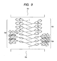
- Gold is vapor-deposited on the thus-obtained polyacetylene film, whereby a device of the polyacetylene film sandwiched between two electrodes as shown in FIG. 9 can be fabricated.
Landscapes
- Chemical & Material Sciences (AREA)
- Engineering & Computer Science (AREA)
- Materials Engineering (AREA)
- Inorganic Chemistry (AREA)
- Health & Medical Sciences (AREA)
- Chemical Kinetics & Catalysis (AREA)
- Medicinal Chemistry (AREA)
- Polymers & Plastics (AREA)
- Organic Chemistry (AREA)
- Graft Or Block Polymers (AREA)
- Addition Polymer Or Copolymer, Post-Treatments, Or Chemical Modifications (AREA)
- Polyoxymethylene Polymers And Polymers With Carbon-To-Carbon Bonds (AREA)
Abstract
Description
- The present invention relates a novel block polymer. The novel block polymer according to the present invention can be applied to a light-emitting layer of a light-emitting device, and a transistor.
- At present, attention is paid to organic electronic devices, such as transistors and light-emitting devices using an organic material. The organic electronic device has a merit of permitting the device itself to be bent. Among others, an electronic device using a conjugated polymer can be fabricated from a solution and thus can be fabricated at low cost. In addition, the device has a merit of permitting its area to be easily enlarged.
- The conjugated polymer permits of realizing highly integrated devices such as monomolecular devices and molecular electronic devices.
- An organic electronic device is generally comprised of a layer device structure with several functional layers stacked on one another, which layers have their respective functions such as electron transport and hole transport. In such a device structure, the functional layers can be freely combined, whereas a problem arises on injection of electrons or holes due to presence of an interface between layers.
- Molecular electronic devices are expected to be applied to memories and sensors, (see, for instance,
US7,105,374 ). However, it is difficult to achieve electric contact between an electrode and a molecule, and it is considered that long-term fundamental researches are required of realization thereof. - Under such circumstances, substituted helical polyacetylene has been proposed as a molecular electronic material of a conjugated system, which is expected to solve the above problems. The substituted helical polyacetylene is disclosed in Japanese Patent Application Laid-Open No.
2004-115628 2004-027182 2004-115628 2004-027182 - A method for producing a stereoregular poly(substituted acetylene) is disclosed in
JP 2004-051684 - However, the substituted polyacetylene disclosed in Japanese Patent Application Laid-Open No.
2004-115628 2004-027182 - An extensive investigation has been carried out repeatedly in view of the above problems, whereby leading to an invention of a block polymer as defined in claim 1. The other claims relate to further developments.
- According to the present invention, novel block polymers applicable to light-emitting layers of light-emitting devices can be provided, and development of novel devices becomes feasible.
- Further features of the present invention will become apparent from the following description of exemplary embodiments with reference to the attached drawings.
-
-
FIG. 1 illustrates an embodiment of the present invention. -
FIG. 2 illustrates another embodiment of the present invention. -
FIG. 3 illustrates the molecular structure of polyacetylene according to an embodiment of the present invention. -
FIG. 4 illustrates the molecular structure of polyacetylene according to the embodiment of the present invention. -
FIG. 5 illustrates the molecular structure of polyacetylene according to the embodiment of the present invention. -
FIG. 6 illustrates the molecular structure of polyacetylene according to the embodiment of the present invention. -
FIG. 7 illustrates a device using a polymer according to an embodiment of the present invention. -
FIGS. 8A and 8B illustrate a production process of a device using a polymer. -
FIG. 9 illustrates a device using a polymer according to another embodiment of the present invention. - The outline of the present invention is described with reference to
FIG. 1 -
FIG. 1 illustrates a block polymer according to the present invention. As illustrated inFIG. 1 , the block polymer has a block A described as 'A' and a block B described as 'B'. In the present invention, the block B becomes a hole-transporting block when the block A is an electron-transporting block. When the block A exhibits N-type conductivity of semiconductors, the block B exhibits P-type conductivity. As illustrated inFIG. 2 , the block polymer may be so formed that a block C is sandwiched between the block A and the block B. In this case, the block C is a luminescent block or a block exhibiting I-type conductivity. - The backbone of the block polymer is a carbon chain, and it is possible to provide a block polymer having functionality as illustrated in
FIG. 1 by using the function of a side chain thereof. A polyacetylene backbone that is a carbon chain of a conjugated system is used The functionality is imparted by varying a side chain. In other words, the backbone becomes a continuous polymer chain, whereby a block polymer having an electron-transporting block and a hole-transporting block can be provided, which means that one having no interface can be provided. Such a construction has an advantage that the transport of an electron or a hole is efficiently conducted. - The backbone structure of a main chain is then described.
FIGS. 3 and4 illustrate cases where the structure of the main chain backbone is of the helical type. InFIG. 3 , amain chain 301 is an acetylene backbone and forms a helix. An electron-transporting block 302 formed with pentafluorophenylacetylene and a hole- transportingblock 303 formed with 4-diphenyl-aminophenylacetylene are formed on side chains of the helical acetylene backbone to provide a block polymer.FIG. 4 is a Y-Z plan view ofFIG. 3 . The plan views of the compound illustrated inFIGS. 3 and4 areFIG. 5 andFIG. 6 . It is inferred fromFIGS. 5 and6 that since no interface is present in the main chain backbone, the transfer of an electron or a hole is efficiently conducted. The molecular chain length is further elongated by synthesis, whereby the molecule becomes a linear rod. This rod is harder than a simple polymer but has higher flexibility than inorganic materials. Therefore, handling of the molecule becomes simple. For example, in a block polymer having an electron-transporting block and a hole-transporting block, both blocks can be sterically separated to reduce unnecessary contact of an electron-transporting portion with a hole-transporting portion compared with a random coil molecule. Therefore, it can be easily inferred that a linear molecule is excellent in light-emitting property and charge separation property compared with an ordinary polymer form. For example, in the case of a light-emitting device having a block polymer with an electron-transporting block, a luminescent block and a hole-transporting block ranging in this order, the electron-transporting block and the hole-transporting block are separated by the luminescent block therebetween, whereby recombination of an electron and a hole is inhibited, and an electron transferred in the electron-transporting block and a hole transferred in the hole-transporting block are recombined in the luminescent block to effectively emit light. An example of the construction of a light-emitting device using such a rod-like helical block polymer is illustrated inFIG. 7 . Alower electrode 705 is located on asubstrate 706, and a rod-likehelical block polymer 702 is arranged on thelower electrode 705. InFIG. 7 , a hole-transporting block 704 is arranged on the side of thelower electrode 705, and an electron-transporting block 703 is arranged on the side of anupper electrode 701. This is determined depending on the correlation with a molecule to which a thiol group is easily introduced upon preparation of a molecule on an electrode. Since the molecule is in the form of a rod, and the transporting directions of the electron and hole are regulated to the helical axis direction of the molecular chain, recombination of the electron and the hole is liable to be accelerated, and improvement in luminous efficiency can be expected. - Other addable constitutions include provision of a functional group having high insulating property (also referred to as an insulating functional group), such as an alkyl group, on a terminal of a side chain. Since the alkyl group is high in insulating property, the outside of the block polymer can be caused to function as an insulating layer by introducing the alkyl group in the terminal of the side chain. This permits the molecule itself to take such a constitution that a conductive wire is covered with an insulating vinyl resin like an electric wiring. The alkyl group may also be selectively introduced, thereby forming an insulating cover portion in a part of the molecule. For example, it is also possible that a part of a P-type or N-type block is exposed for bringing both terminals into contact with respective electrodes, and a central part is covered with an insulating cover portion. Quite naturally, only one terminal may be exposed, and it is also considered that an intermediate part of the block polymer is exposed to bring it into contact with another block polymer. An alkyl chain may be provided at a terminal of the side chain, thereby covering the outside of the molecule with the insulating cover portion to control the electron and hole so as to transfer only within the molecule. In other words, a conductive molecule with intermolecular recombination of an electron and a hole inhibited by insulating the molecule with the insulating cover portion can be provided. In addition, molecule design is easy because a range of selection of the side chain is wide, and so a possibility that a device is fabricated according to a desired plan becomes high.
- A block is formed by polymerizing the same monomer. However, plural kinds of monomers may be used so far as a block formed by polymerization exhibits electron-transporting property or hole-transporting property, as described above. At least 10 units are necessary as one block. Fifty units or more and less than 1,000 units are favorable. Since the upper limit thereof varies according to uses, the units may be suitably selected according to uses. For example, when an electron-transporting block is synthesized with plural kinds of monomers, the synthesis may be conducted by first using a monomer high in electron-transporting property and mixing a small amount of a monomer low in electron-transporting property in the middle of the synthesis. The synthesis is conducted in this manner, thereby permitting making a difference in electron-transporting property even in a block. When another block is prepared, it is also possible to select a monomer easy to be introduced taking into account the circumstances of a compound or functional group to be introduced into a side chain in said another block. For example, when a monomer having a hydrogen-bonding functional group such as a hydroxyl group or amide group is selected for a block also having a hydrogen-bonding functional group, the bonding between blocks becomes firm due to hydrogen bonding between the functional groups, so that the block is easy to be prepared.
- A side chain to be introduced into a block is selected according to functions.
- For example, for an electron-transporting block, it is only necessary to introduce an electron-transporting material into a side chain of the block. The electron-transporting side chain is only required to contain the structure of the electron-transporting material. A structure derived from an electron-transporting material or a substituent of a side-chain type electron-transporting polymeric material may also be used.
- Specific examples thereof include the following functional groups:
- Functional groups having an sp2 nitrogen atom, such as pyridine derivatives, pyrimidine derivatives, pyrazine derivatives, quinoline derivatives, triazole derivatives, oxazole derivatives, oxadiazole derivatives, thiazole derivatives and thiadiazole derivatives; and functional groups containing a fluorenone derivative, anthraquinonedimethane derivative, quinodimethane derivative, diphenoquinone derivative, coumarin derivative, cyanated aromatic derivative or fluorinated aromatic derivative.
- The hole-transporting side chain is only required to contain the structure of the hole-transporting material. A structure derived from a hole-transporting material or a substituent of a side-chain type hole-transporting polymeric material may also be used.
- Specific examples thereof include the following functional groups:
- Functional groups containing a tertiary amine such as a triphenylamine derivative, carbazole derivative, imidazole derivative or phenylenediamine derivative; and functional groups containing an oligothiophene derivative, tetrathiafulvalene derivative, porphyrin derivative, phthalocyanine derivative, stilbene derivative or fused aromatic derivative.
- For a luminescent block, it is only necessary to introduce a luminescent material into a side chain. The luminescent side chain is only required to contain the structure of a fluorescent material or electroluminescent material. A structure derived from a fluorescent material or electroluminescent material or a substituent of a side-chain type polymeric luminescent material may also be used.
- Specific examples thereof include the following functional groups:
- Functional groups containing a carbazole derivative, fluorene derivative, quinoline derivative, coumarin derivative, triazole derivative, aromatic amine derivative, fused aromatic derivative, completely fluorinated aromatic derivative, tris(8-hydroquinoline)-aluminum complex, tris(2-phenylpyridyl)iridium complex or any other luminescent metal complex.
- The block polymer composed of the electron-transporting block and the hole-transporting block, which is the block polymer according to the present invention, can be used as a light-emitting layer of a light-emitting device, as described above. However, the following application may also be considered.
- When the block polymer is irradiated with light, charges are generated in electrons of the block polymer, and then the charges are gathered at both terminals of the block polymer molecule, thereby generating a potential difference between both terminals of the block polymer molecule. The thus-generated potential difference can be utilized. Since electrolysis is caused when water is brought into contact, the potential difference can be used for conducting electrolysis of water.
- In addition, the wavelength of excitation light can be changed by adjusting the side chain of the block polymer molecule, and so a wide variety of light from ultraviolet light to visible light can be utilized. A contact area between a water molecule and both terminals of the polymer molecule, which correspond to electrode parts, can be greatly increased to conduct the electrolysis of water with high efficiency.
- A preparation process of a substituted polyacetylene block polymer in the present invention and a fabrication process of a device structure of the substituted polyacetylene block polymer and electrodes will hereinafter be described.
- A test tube closed after subjected to pressure reduction and purging with nitrogen is charged with 30 mg (6.5 × 10⁻⁶ mol) of a dimer of rhodium (norbornadiene) chloride, and is evacuated under reduced pressure and purged with nitrogen after closely sealed with a septum cap. Thereafter, 100 mg (1.19 × 10⁻³ mol) of triethylamine as a promoter and 10 ml of toluene as a solvent are put therein, and the contents are stirred for 30 minutes at 30°C. A mixed solution of 1.25 g (6.5 × 10⁻³ mol) of pentafluorophenylacetylene represented by Formula 1 and 2.0 ml of toluene is poured into the thus-obtained toluene solution of the rhodium complex, thereby initiating a polymerization reaction. The reaction is conducted for 1 hour at 30°C, and a mixed solution of 1.75 g (6.5 × 10⁻³ mol) of 4-diphenylaminophenylacetylene represented by Formula 2 and 2.0 ml of toluene is poured therein after polymerization is allowed to sufficiently progress. The polymerization reaction is further conducted. The reaction is conducted for 2 hours at 30°C, and the resultant polymer is washed with a largely excess amount of methanol, separated by filtration and then vacuum-dried for 24 hours, thereby obtaining a polyacetylene block polymer [poly((pentafluorophenylacetylene)-co-(4-diphenylamino-phenylacetylene))] illustrated in
FIG. 4 . - Whether the intended product was obtained or not was confirmed by measuring 1H-NMR of the block polymer and homopolymers to measure signals of the phenyl group and the methine group of the main chain. The molecular weights of the block polymer and homopolymers were measured by gel permeation chromatography (GPC, solvent: THF) to confirm that two blocks are bonded to form a block polymer, since the molecular weight changed in accordance with the calculated value.


- A test tube closed after subjected to pressure reduction and purging with nitrogen is charged with 12.0 mg (2.5 × 10⁻⁵ mol) of a dimer of rhodium (norbornadiene) chloride and 10 ml of toluene. After the contents are stirred for 15 minutes at 0°C, a toluene solution of 0.1 mol/l of 1,1,2-triphenylvinyl-lithium is poured therein, and the resultant mixture is stirred for 10 minutes. Further, 1.6 ml of a toluene solution of 0.1 mol/l of triphenylphosphine as a promoter is poured, and the contents are stirred for 20 minutes.
- A mixed solution of 1.25 g (6.5 × 10⁻³ mol) of pentafluorophenylacetylene and 2.0 ml of toluene is poured into the above-obtained toluene solution of the rhodium complex, thereby initiating a polymerization reaction. The reaction is conducted for 1 hour at 30°C, and a mixed solution of 0.175g (6.5 × 10⁻³ mol) of 4-diphenylaminophenylacetylene and 2.0 ml of toluene is poured therein after polymerization is allowed to sufficiently progress, thereby further conducting the polymerization reaction. The reaction is conducted for 2 hours at 30°C, and the resultant polymer is washed with a largely excess amount of methanol, separated by filtration and then vacuum-dried for 24 hours, thereby obtaining the intended polyacetylene block polymer [poly((pentafluorophenylacetylene)-co-(4-diphenylaminophenylacetylene))].
- Pentafluorophenylacetylene is polymerized with 4-(N-carbazolyl)phenylacetylene represented by Formula 3 according to the same process as in Example 2, thereby obtaining the intended polyacetylene block polymer [poly((4-(N-carbazolyl)phenylacetylene)-co-(4-pentafluorophenylacetylene))].


- 3-Ethynylquinoline represented by Formula 4 is polymerized with 3-ethynyl-7-ethylhexylcarbazole represented by Formula 5 according to the same process as in Example 2, thereby obtaining the intended polyacetylene block polymer [poly((3-ethynylquinoline)-co-(3-ethynyl-7-ethylhexylcarbazole))].


- 3-Ethynylquinoline represented by Formula 4 is polymerized with 4-di(3,4-ethylenedioxyphenyl)-aminoacetylene represented by Formula 6 according to the same process as in Example 2, thereby obtaining the intended polyacetylene block polymer [poly((3-ethynylquinoline)-co-(4-di(3,4-ethylenedioxyphenyl)-aminoacetylene))].

- As described above, various kinds of novel block polymers can be provided.
- A device in this example can be fabricated in the following manner.
- After an ITO substrate is ultrasonically washed for 15 minutes in ethanol, the substrate is dried and immersed for 20 minutes in concentrated sulfuric acid. After the substrate is then washed with ultrapure water, the substrate is immersed for 15 minutes in a 1:1 solution of a 30% aqueous solution of hydrogen peroxide and a 28% aqueous solution of ammonia at 80°C, further washed with ultrapure water and dried with nitrogen gas. An ITO substrate having a hydrophilic surface is obtained in the above-described manner.
- The poly((3-ethynylquinoline)-co-(4-di(3,4-ethylenedioxyphenyl)aminoacetylene)) obtained by the process in Example 5 is dissolved in chloroform to prepare a solution having a concentration of 0.5 mg/mL. This solution (500 µL) is added dropwise at a rate of 2 µL/sec to the surface of ultrapure water filled in a water vessel 801 (width: 40 cm) illustrated in
FIGS. 8A and 8B and having an initial surface area of 2,700 cm2 when a moving barrier 803 is located at the left end. After completion of the drop addition, the moving barrier 803 is moved in a direction of anarrow 806 to control it such that the value of afilm pressure gauge 802 reaches 25 mN/m, thereby forming adeveloped film 805 of the helical substituted polyacetylene on the water surface. - The
ITO substrate 804 subjected to the hydrophilization treatment according to the process described above is placed under thedeveloped film 805 on the water surface in thewater vessel 801 in advance and is caused to rise at a rate of 0.3 mm/sec, thereby transferring thedeveloped film 805 on theglass substrate 804 to obtain a polymer film vertically oriented on the glass substrate. - Gold is vapor-deposited on the thus-obtained polyacetylene film, whereby a device of the polyacetylene film sandwiched between two electrodes as shown in
FIG. 9 can be fabricated. - While the present invention has been described with reference to exemplary embodiments, it is to be understood that the invention is not limited to the disclosed exemplary embodiments.
- This application claims the benefit of Japanese Patent Application No.
2008-006930, filed January 16, 2008
Claims (3)
- A block polymer of which a main chain (301) backbone is helical polyacetylene,
wherein each block of the polymer has at least 10 repeating units, characterized in that the block polymer comprises an electron-transporting block (A, 302) and a hole-transporting block (B, 303). - The block polymer according to claim 1, which has a luminescent block (C) between the electron-transporting block and the hole-transporting block.
- The block polymer according to claim 1, wherein the block polymer has an insulating cover portion in at least a part thereof.
Applications Claiming Priority (2)
| Application Number | Priority Date | Filing Date | Title |
|---|---|---|---|
| JP2008006930A JP5473225B2 (en) | 2008-01-16 | 2008-01-16 | Block polymer |
| PCT/JP2008/073889 WO2009090852A1 (en) | 2008-01-16 | 2008-12-19 | Block polymer |
Publications (2)
| Publication Number | Publication Date |
|---|---|
| EP2235081A1 EP2235081A1 (en) | 2010-10-06 |
| EP2235081B1 true EP2235081B1 (en) | 2011-09-07 |
Family
ID=40518599
Family Applications (1)
| Application Number | Title | Priority Date | Filing Date |
|---|---|---|---|
| EP08870864A Not-in-force EP2235081B1 (en) | 2008-01-16 | 2008-12-19 | Block polymer |
Country Status (5)
| Country | Link |
|---|---|
| US (1) | US8697809B2 (en) |
| EP (1) | EP2235081B1 (en) |
| JP (1) | JP5473225B2 (en) |
| AT (1) | ATE523534T1 (en) |
| WO (1) | WO2009090852A1 (en) |
Families Citing this family (3)
| Publication number | Priority date | Publication date | Assignee | Title |
|---|---|---|---|---|
| JP5596912B2 (en) * | 2007-08-31 | 2014-09-24 | キヤノン株式会社 | Block polymers and devices |
| EP2492294A1 (en) * | 2011-02-28 | 2012-08-29 | Canon Kabushiki Kaisha | Helical-polyacetylene and device having the helical-polyacetylene |
| JP5980659B2 (en) * | 2012-11-13 | 2016-08-31 | 国立大学法人京都大学 | Polymer having carbazole group, monomer and compound having carbazole group |
Family Cites Families (8)
| Publication number | Priority date | Publication date | Assignee | Title |
|---|---|---|---|---|
| JPH09157329A (en) * | 1995-12-07 | 1997-06-17 | Kagaku Gijutsu Shinko Jigyodan | Method for producing substituted acetylene polymer |
| US6291606B1 (en) * | 1997-03-21 | 2001-09-18 | The Hong Kong University Of Science And Technology | Highly stereoregular polyacetylenes from organorhodium catalysts in aqueous media |
| JP2004027182A (en) | 2002-02-28 | 2004-01-29 | Masayoshi Tabata | Polymer and polymeric composition of which shape and peak position of absorption/emission spectrum change reversibly |
| JP2004051684A (en) * | 2002-07-17 | 2004-02-19 | Idemitsu Petrochem Co Ltd | Production method for stereoregular poly(substituted acetylene) |
| JP3903176B2 (en) | 2002-09-25 | 2007-04-11 | 独立行政法人産業技術総合研究所 | Method for producing black polyacetylene compound and method for regenerating yellow polyacetylene compound |
| US7105374B1 (en) * | 2005-01-12 | 2006-09-12 | Spansion Llc | Memory cell containing copolymer containing diarylacetylene portion |
| JP5111024B2 (en) * | 2007-08-31 | 2012-12-26 | キヤノン株式会社 | Block polymers, metal and block polymer composites and devices |
| JP5596912B2 (en) * | 2007-08-31 | 2014-09-24 | キヤノン株式会社 | Block polymers and devices |
-
2008
- 2008-01-16 JP JP2008006930A patent/JP5473225B2/en not_active Expired - Fee Related
- 2008-12-19 WO PCT/JP2008/073889 patent/WO2009090852A1/en not_active Ceased
- 2008-12-19 US US12/744,211 patent/US8697809B2/en not_active Expired - Fee Related
- 2008-12-19 EP EP08870864A patent/EP2235081B1/en not_active Not-in-force
- 2008-12-19 AT AT08870864T patent/ATE523534T1/en not_active IP Right Cessation
Also Published As
| Publication number | Publication date |
|---|---|
| JP5473225B2 (en) | 2014-04-16 |
| WO2009090852A1 (en) | 2009-07-23 |
| US8697809B2 (en) | 2014-04-15 |
| US20100286336A1 (en) | 2010-11-11 |
| JP2009167293A (en) | 2009-07-30 |
| ATE523534T1 (en) | 2011-09-15 |
| EP2235081A1 (en) | 2010-10-06 |
Similar Documents
| Publication | Publication Date | Title |
|---|---|---|
| Chen et al. | A Family of Electroluminescent Silyl-Substituted Poly (p-phenylenevinylene) s: Synthesis, Characterization, and Structure− Property Relationships | |
| US6399224B1 (en) | Conjugated polymers with tunable charge injection ability | |
| Frampton et al. | Insulated molecular wires | |
| JP7021948B2 (en) | Organic luminescent polymers containing luminescent repeating units in the polymer backbone and devices using them | |
| Lu et al. | Polyfluorene-based light-emitting rod− coil block copolymers | |
| US20080015269A1 (en) | Hybrid polymer light-emitting devices | |
| KR102136186B1 (en) | Charge transporting semi-conducting material and semi-conducting device | |
| Egbe et al. | Investigation of the Photophysical and Electrochemical Properties of Alkoxy-Substituted Arylene− Ethynylene/Arylene− Vinylene Hybrid Polymers | |
| Usluer et al. | Fluorene‐carbazole dendrimers: Synthesis, thermal, photophysical and electroluminescent device properties | |
| Tsai et al. | Single-component polyfluorene electrolytes bearing different counterions for white light-emitting electrochemical cells | |
| Kang et al. | Highly bright and efficient electroluminescence of new PPV derivatives containing polyhedral oligomeric silsesquioxanes (POSSs) and their blends | |
| Cho et al. | Synthesis of Diphenylamine‐Substituted Phenylazomethine Dendrimers and the Performance of Organic Light‐Emitting Diodes | |
| US8697809B2 (en) | Block polymer | |
| Son et al. | Synthesis of polymers for hole and electron transport materials in organic electroluminescent devices | |
| Yang et al. | Synthesis and electroluminescent properties of disubstituted polyacetylene derivatives containing multi‐fluorophenyl and cyclohexylphenyl side groups | |
| TW200916474A (en) | Phosphorescent polymer compounds and organic electroluminescent devices manufactured therewith | |
| US8450724B2 (en) | Electrical device containing helical substituted polyacetylene | |
| Chen et al. | Poly (2, 3-diphenyl-1, 4-phenylenevinylene)(DP-PPV) derivatives: Synthesis, properties, and their applications in polymer light-emitting diodes | |
| Li et al. | Synthesis and optical properties of dendronized porphyrin polymers | |
| Vellis et al. | Carbazolevinylene‐based polymers and model compounds with oxadiazole and triphenylamine segments: Synthesis, photophysics, and electroluminescence | |
| Yu et al. | Multifunctional hyperbranched oligo (fluorene vinylene) containing pendant crown ether: synthesis, chemosensory, and electroluminescent properties | |
| Ha et al. | Synthesis and characterization of novel light-emitting copolymers containing triphenylamine derivatives | |
| Wang et al. | Synthesis, characterization and nanoaggregates of alkyl and triethylene glycol substituted 3, 6-carbazolevinylenes homopolymers and block copolymers | |
| Yang et al. | A novel mesogen‐jacketed liquid crystalline electroluminescent polymer with both thiophene and oxadiazole in conjugated side chain | |
| Mahbub et al. | Beads on a chain fluorescent oligomeric materials: Interactions of conjugated organic cross-linkers with silsesquioxane cages |
Legal Events
| Date | Code | Title | Description |
|---|---|---|---|
| PUAI | Public reference made under article 153(3) epc to a published international application that has entered the european phase |
Free format text: ORIGINAL CODE: 0009012 |
|
| 17P | Request for examination filed |
Effective date: 20100723 |
|
| AK | Designated contracting states |
Kind code of ref document: A1 Designated state(s): AT BE BG CH CY CZ DE DK EE ES FI FR GB GR HR HU IE IS IT LI LT LU LV MC MT NL NO PL PT RO SE SI SK TR |
|
| AX | Request for extension of the european patent |
Extension state: AL BA MK RS |
|
| GRAP | Despatch of communication of intention to grant a patent |
Free format text: ORIGINAL CODE: EPIDOSNIGR1 |
|
| DAX | Request for extension of the european patent (deleted) | ||
| GRAS | Grant fee paid |
Free format text: ORIGINAL CODE: EPIDOSNIGR3 |
|
| GRAA | (expected) grant |
Free format text: ORIGINAL CODE: 0009210 |
|
| REG | Reference to a national code |
Ref country code: GB Ref legal event code: FG4D |
|
| REG | Reference to a national code |
Ref country code: CH Ref legal event code: EP |
|
| REG | Reference to a national code |
Ref country code: IE Ref legal event code: FG4D |
|
| REG | Reference to a national code |
Ref country code: DE Ref legal event code: R096 Ref document number: 602008009677 Country of ref document: DE Effective date: 20111110 |
|
| REG | Reference to a national code |
Ref country code: NL Ref legal event code: VDEP Effective date: 20110907 |
|
| PG25 | Lapsed in a contracting state [announced via postgrant information from national office to epo] |
Ref country code: HR Free format text: LAPSE BECAUSE OF FAILURE TO SUBMIT A TRANSLATION OF THE DESCRIPTION OR TO PAY THE FEE WITHIN THE PRESCRIBED TIME-LIMIT Effective date: 20110907 Ref country code: FI Free format text: LAPSE BECAUSE OF FAILURE TO SUBMIT A TRANSLATION OF THE DESCRIPTION OR TO PAY THE FEE WITHIN THE PRESCRIBED TIME-LIMIT Effective date: 20110907 Ref country code: LT Free format text: LAPSE BECAUSE OF FAILURE TO SUBMIT A TRANSLATION OF THE DESCRIPTION OR TO PAY THE FEE WITHIN THE PRESCRIBED TIME-LIMIT Effective date: 20110907 Ref country code: NO Free format text: LAPSE BECAUSE OF FAILURE TO SUBMIT A TRANSLATION OF THE DESCRIPTION OR TO PAY THE FEE WITHIN THE PRESCRIBED TIME-LIMIT Effective date: 20111207 Ref country code: SE Free format text: LAPSE BECAUSE OF FAILURE TO SUBMIT A TRANSLATION OF THE DESCRIPTION OR TO PAY THE FEE WITHIN THE PRESCRIBED TIME-LIMIT Effective date: 20110907 |
|
| LTIE | Lt: invalidation of european patent or patent extension |
Effective date: 20110907 |
|
| PG25 | Lapsed in a contracting state [announced via postgrant information from national office to epo] |
Ref country code: SI Free format text: LAPSE BECAUSE OF FAILURE TO SUBMIT A TRANSLATION OF THE DESCRIPTION OR TO PAY THE FEE WITHIN THE PRESCRIBED TIME-LIMIT Effective date: 20110907 Ref country code: CY Free format text: LAPSE BECAUSE OF FAILURE TO SUBMIT A TRANSLATION OF THE DESCRIPTION OR TO PAY THE FEE WITHIN THE PRESCRIBED TIME-LIMIT Effective date: 20110907 Ref country code: AT Free format text: LAPSE BECAUSE OF FAILURE TO SUBMIT A TRANSLATION OF THE DESCRIPTION OR TO PAY THE FEE WITHIN THE PRESCRIBED TIME-LIMIT Effective date: 20110907 Ref country code: LV Free format text: LAPSE BECAUSE OF FAILURE TO SUBMIT A TRANSLATION OF THE DESCRIPTION OR TO PAY THE FEE WITHIN THE PRESCRIBED TIME-LIMIT Effective date: 20110907 Ref country code: GR Free format text: LAPSE BECAUSE OF FAILURE TO SUBMIT A TRANSLATION OF THE DESCRIPTION OR TO PAY THE FEE WITHIN THE PRESCRIBED TIME-LIMIT Effective date: 20111208 |
|
| REG | Reference to a national code |
Ref country code: AT Ref legal event code: MK05 Ref document number: 523534 Country of ref document: AT Kind code of ref document: T Effective date: 20110907 |
|
| PG25 | Lapsed in a contracting state [announced via postgrant information from national office to epo] |
Ref country code: BE Free format text: LAPSE BECAUSE OF FAILURE TO SUBMIT A TRANSLATION OF THE DESCRIPTION OR TO PAY THE FEE WITHIN THE PRESCRIBED TIME-LIMIT Effective date: 20110907 |
|
| PG25 | Lapsed in a contracting state [announced via postgrant information from national office to epo] |
Ref country code: IS Free format text: LAPSE BECAUSE OF FAILURE TO SUBMIT A TRANSLATION OF THE DESCRIPTION OR TO PAY THE FEE WITHIN THE PRESCRIBED TIME-LIMIT Effective date: 20120107 Ref country code: SK Free format text: LAPSE BECAUSE OF FAILURE TO SUBMIT A TRANSLATION OF THE DESCRIPTION OR TO PAY THE FEE WITHIN THE PRESCRIBED TIME-LIMIT Effective date: 20110907 Ref country code: CZ Free format text: LAPSE BECAUSE OF FAILURE TO SUBMIT A TRANSLATION OF THE DESCRIPTION OR TO PAY THE FEE WITHIN THE PRESCRIBED TIME-LIMIT Effective date: 20110907 |
|
| PG25 | Lapsed in a contracting state [announced via postgrant information from national office to epo] |
Ref country code: RO Free format text: LAPSE BECAUSE OF FAILURE TO SUBMIT A TRANSLATION OF THE DESCRIPTION OR TO PAY THE FEE WITHIN THE PRESCRIBED TIME-LIMIT Effective date: 20110907 Ref country code: PT Free format text: LAPSE BECAUSE OF FAILURE TO SUBMIT A TRANSLATION OF THE DESCRIPTION OR TO PAY THE FEE WITHIN THE PRESCRIBED TIME-LIMIT Effective date: 20120109 Ref country code: EE Free format text: LAPSE BECAUSE OF FAILURE TO SUBMIT A TRANSLATION OF THE DESCRIPTION OR TO PAY THE FEE WITHIN THE PRESCRIBED TIME-LIMIT Effective date: 20110907 Ref country code: IT Free format text: LAPSE BECAUSE OF FAILURE TO SUBMIT A TRANSLATION OF THE DESCRIPTION OR TO PAY THE FEE WITHIN THE PRESCRIBED TIME-LIMIT Effective date: 20110907 Ref country code: NL Free format text: LAPSE BECAUSE OF FAILURE TO SUBMIT A TRANSLATION OF THE DESCRIPTION OR TO PAY THE FEE WITHIN THE PRESCRIBED TIME-LIMIT Effective date: 20110907 Ref country code: PL Free format text: LAPSE BECAUSE OF FAILURE TO SUBMIT A TRANSLATION OF THE DESCRIPTION OR TO PAY THE FEE WITHIN THE PRESCRIBED TIME-LIMIT Effective date: 20110907 |
|
| PLBE | No opposition filed within time limit |
Free format text: ORIGINAL CODE: 0009261 |
|
| STAA | Information on the status of an ep patent application or granted ep patent |
Free format text: STATUS: NO OPPOSITION FILED WITHIN TIME LIMIT |
|
| PG25 | Lapsed in a contracting state [announced via postgrant information from national office to epo] |
Ref country code: DK Free format text: LAPSE BECAUSE OF FAILURE TO SUBMIT A TRANSLATION OF THE DESCRIPTION OR TO PAY THE FEE WITHIN THE PRESCRIBED TIME-LIMIT Effective date: 20110907 Ref country code: MC Free format text: LAPSE BECAUSE OF NON-PAYMENT OF DUE FEES Effective date: 20111231 |
|
| 26N | No opposition filed |
Effective date: 20120611 |
|
| REG | Reference to a national code |
Ref country code: IE Ref legal event code: MM4A |
|
| REG | Reference to a national code |
Ref country code: DE Ref legal event code: R097 Ref document number: 602008009677 Country of ref document: DE Effective date: 20120611 |
|
| PG25 | Lapsed in a contracting state [announced via postgrant information from national office to epo] |
Ref country code: IE Free format text: LAPSE BECAUSE OF NON-PAYMENT OF DUE FEES Effective date: 20111219 |
|
| PG25 | Lapsed in a contracting state [announced via postgrant information from national office to epo] |
Ref country code: MT Free format text: LAPSE BECAUSE OF FAILURE TO SUBMIT A TRANSLATION OF THE DESCRIPTION OR TO PAY THE FEE WITHIN THE PRESCRIBED TIME-LIMIT Effective date: 20110907 |
|
| PG25 | Lapsed in a contracting state [announced via postgrant information from national office to epo] |
Ref country code: ES Free format text: LAPSE BECAUSE OF FAILURE TO SUBMIT A TRANSLATION OF THE DESCRIPTION OR TO PAY THE FEE WITHIN THE PRESCRIBED TIME-LIMIT Effective date: 20111218 |
|
| PG25 | Lapsed in a contracting state [announced via postgrant information from national office to epo] |
Ref country code: LU Free format text: LAPSE BECAUSE OF NON-PAYMENT OF DUE FEES Effective date: 20111219 |
|
| PG25 | Lapsed in a contracting state [announced via postgrant information from national office to epo] |
Ref country code: BG Free format text: LAPSE BECAUSE OF FAILURE TO SUBMIT A TRANSLATION OF THE DESCRIPTION OR TO PAY THE FEE WITHIN THE PRESCRIBED TIME-LIMIT Effective date: 20111207 |
|
| REG | Reference to a national code |
Ref country code: CH Ref legal event code: PL |
|
| PG25 | Lapsed in a contracting state [announced via postgrant information from national office to epo] |
Ref country code: TR Free format text: LAPSE BECAUSE OF FAILURE TO SUBMIT A TRANSLATION OF THE DESCRIPTION OR TO PAY THE FEE WITHIN THE PRESCRIBED TIME-LIMIT Effective date: 20110907 |
|
| PG25 | Lapsed in a contracting state [announced via postgrant information from national office to epo] |
Ref country code: LI Free format text: LAPSE BECAUSE OF NON-PAYMENT OF DUE FEES Effective date: 20121231 Ref country code: HU Free format text: LAPSE BECAUSE OF FAILURE TO SUBMIT A TRANSLATION OF THE DESCRIPTION OR TO PAY THE FEE WITHIN THE PRESCRIBED TIME-LIMIT Effective date: 20110907 Ref country code: CH Free format text: LAPSE BECAUSE OF NON-PAYMENT OF DUE FEES Effective date: 20121231 |
|
| REG | Reference to a national code |
Ref country code: FR Ref legal event code: PLFP Year of fee payment: 8 |
|
| PGFP | Annual fee paid to national office [announced via postgrant information from national office to epo] |
Ref country code: GB Payment date: 20151218 Year of fee payment: 8 |
|
| PGFP | Annual fee paid to national office [announced via postgrant information from national office to epo] |
Ref country code: FR Payment date: 20151223 Year of fee payment: 8 |
|
| PGFP | Annual fee paid to national office [announced via postgrant information from national office to epo] |
Ref country code: DE Payment date: 20151231 Year of fee payment: 8 |
|
| REG | Reference to a national code |
Ref country code: DE Ref legal event code: R119 Ref document number: 602008009677 Country of ref document: DE |
|
| GBPC | Gb: european patent ceased through non-payment of renewal fee |
Effective date: 20161219 |
|
| REG | Reference to a national code |
Ref country code: FR Ref legal event code: ST Effective date: 20170831 |
|
| PG25 | Lapsed in a contracting state [announced via postgrant information from national office to epo] |
Ref country code: FR Free format text: LAPSE BECAUSE OF NON-PAYMENT OF DUE FEES Effective date: 20170102 |
|
| PG25 | Lapsed in a contracting state [announced via postgrant information from national office to epo] |
Ref country code: DE Free format text: LAPSE BECAUSE OF NON-PAYMENT OF DUE FEES Effective date: 20170701 Ref country code: GB Free format text: LAPSE BECAUSE OF NON-PAYMENT OF DUE FEES Effective date: 20161219 |