EP2234845B1 - A vehicle safety system - Google Patents
A vehicle safety system Download PDFInfo
- Publication number
- EP2234845B1 EP2234845B1 EP08705367.4A EP08705367A EP2234845B1 EP 2234845 B1 EP2234845 B1 EP 2234845B1 EP 08705367 A EP08705367 A EP 08705367A EP 2234845 B1 EP2234845 B1 EP 2234845B1
- Authority
- EP
- European Patent Office
- Prior art keywords
- vehicle
- sensors
- deployment algorithm
- driving lane
- entering
- Prior art date
- Legal status (The legal status is an assumption and is not a legal conclusion. Google has not performed a legal analysis and makes no representation as to the accuracy of the status listed.)
- Not-in-force
Links
Images
Classifications
-
- B—PERFORMING OPERATIONS; TRANSPORTING
- B60—VEHICLES IN GENERAL
- B60R—VEHICLES, VEHICLE FITTINGS, OR VEHICLE PARTS, NOT OTHERWISE PROVIDED FOR
- B60R21/00—Arrangements or fittings on vehicles for protecting or preventing injuries to occupants or pedestrians in case of accidents or other traffic risks
- B60R21/01—Electrical circuits for triggering passive safety arrangements, e.g. airbags, safety belt tighteners, in case of vehicle accidents or impending vehicle accidents
- B60R21/013—Electrical circuits for triggering passive safety arrangements, e.g. airbags, safety belt tighteners, in case of vehicle accidents or impending vehicle accidents including means for detecting collisions, impending collisions or roll-over
- B60R21/0136—Electrical circuits for triggering passive safety arrangements, e.g. airbags, safety belt tighteners, in case of vehicle accidents or impending vehicle accidents including means for detecting collisions, impending collisions or roll-over responsive to actual contact with an obstacle, e.g. to vehicle deformation, bumper displacement or bumper velocity relative to the vehicle
-
- B—PERFORMING OPERATIONS; TRANSPORTING
- B60—VEHICLES IN GENERAL
- B60R—VEHICLES, VEHICLE FITTINGS, OR VEHICLE PARTS, NOT OTHERWISE PROVIDED FOR
- B60R21/00—Arrangements or fittings on vehicles for protecting or preventing injuries to occupants or pedestrians in case of accidents or other traffic risks
- B60R2021/0002—Type of accident
- B60R2021/0006—Lateral collision
-
- B—PERFORMING OPERATIONS; TRANSPORTING
- B60—VEHICLES IN GENERAL
- B60R—VEHICLES, VEHICLE FITTINGS, OR VEHICLE PARTS, NOT OTHERWISE PROVIDED FOR
- B60R21/00—Arrangements or fittings on vehicles for protecting or preventing injuries to occupants or pedestrians in case of accidents or other traffic risks
- B60R21/01—Electrical circuits for triggering passive safety arrangements, e.g. airbags, safety belt tighteners, in case of vehicle accidents or impending vehicle accidents
- B60R21/013—Electrical circuits for triggering passive safety arrangements, e.g. airbags, safety belt tighteners, in case of vehicle accidents or impending vehicle accidents including means for detecting collisions, impending collisions or roll-over
- B60R21/0132—Electrical circuits for triggering passive safety arrangements, e.g. airbags, safety belt tighteners, in case of vehicle accidents or impending vehicle accidents including means for detecting collisions, impending collisions or roll-over responsive to vehicle motion parameters, e.g. to vehicle longitudinal or transversal deceleration or speed value
- B60R2021/01327—Angular velocity or angular acceleration
-
- B—PERFORMING OPERATIONS; TRANSPORTING
- B60—VEHICLES IN GENERAL
- B60R—VEHICLES, VEHICLE FITTINGS, OR VEHICLE PARTS, NOT OTHERWISE PROVIDED FOR
- B60R21/00—Arrangements or fittings on vehicles for protecting or preventing injuries to occupants or pedestrians in case of accidents or other traffic risks
- B60R21/01—Electrical circuits for triggering passive safety arrangements, e.g. airbags, safety belt tighteners, in case of vehicle accidents or impending vehicle accidents
- B60R21/013—Electrical circuits for triggering passive safety arrangements, e.g. airbags, safety belt tighteners, in case of vehicle accidents or impending vehicle accidents including means for detecting collisions, impending collisions or roll-over
- B60R21/0134—Electrical circuits for triggering passive safety arrangements, e.g. airbags, safety belt tighteners, in case of vehicle accidents or impending vehicle accidents including means for detecting collisions, impending collisions or roll-over responsive to imminent contact with an obstacle, e.g. using radar systems
-
- B—PERFORMING OPERATIONS; TRANSPORTING
- B60—VEHICLES IN GENERAL
- B60W—CONJOINT CONTROL OF VEHICLE SUB-UNITS OF DIFFERENT TYPE OR DIFFERENT FUNCTION; CONTROL SYSTEMS SPECIALLY ADAPTED FOR HYBRID VEHICLES; ROAD VEHICLE DRIVE CONTROL SYSTEMS FOR PURPOSES NOT RELATED TO THE CONTROL OF A PARTICULAR SUB-UNIT
- B60W30/00—Purposes of road vehicle drive control systems not related to the control of a particular sub-unit, e.g. of systems using conjoint control of vehicle sub-units
- B60W30/10—Path keeping
- B60W30/12—Lane keeping
Definitions
- WO2005/118348 discloses a safety system for vehicle occupants according to the preambles of claims 1 and 10, having sensors for acquiring crash-relevant data such as acceleration and/or pressure values, having a control device, and having restraints, such as an air bag, safety belt, or the like.
- the safety system 1 has a connection to a navigation system of the vehicle. Data of the navigation system of the vehicle, such as in particular location data of the vehicle, are supplied to the safety system and are taken into account in a triggering decision for restraint.
- US2006267748 discloses a method for preventing collisions of vehicles, in which first the surroundings of a vehicle and motion parameters of the vehicle are detected by means of sensors. From the output signals of the sensors, a failure-to-yield criterion and a collision risk criterion are derived. From a combination of the failure-to-yield criterion and the collision risk criterion, a risk level is ascertained. Depending on the particular risk level ascertained, finally, steps for reducing the risk of collision are initiated.
- Deployment of the safety systems will be controlled by an on-board processor, in accordance with a deployment algorithm.
- a deployment algorithm There are, however, competing priorities which must be taken into account when formulating the algorithm.
- the relevant side impact safety systems must be activated as swiftly as possible in the event of a crash situation occurring.
- the algorithm must be robust against "false positive" determinations, which could lead to the side impact safety systems being deployed unnecessarily. Such situations may include the door of a vehicle being slammed with above average force, and low-impact crashes that are unlikely to cause harm to vehicle occupants. It will therefore be understood that deployment algorithms are generally a compromise between these two competing priorities.
- one aspect of the present invention provides a vehicle safety system comprising: at least one occupant safety device for protecting an occupant of the vehicle in the event of an impact of a predetermined type; and a control unit operable to receive information from one or more vehicle sensors and to provide a trigger signal to activate the occupant safety device, wherein: under normal driving conditions, a default deployment algorithm is used by the control unit to determine whether the trigger signal should be generated; and if it is determined that the vehicle is entering or crossing another driving lane, or is about to do so, the control unit employs a further deployment algorithm to determine whether the trigger signal should be generated, the further deployment algorithm being adapted to cause the trigger signal to be generated a shorter time after the initiation of an impact of the predetermined type than is the case for the default deployment algorithm; the sensors include sensors for measuring movement and/or control of the vehicle, and the control unit is operable to make a determination, from data output from these sensors, as to whether the vehicle is entering or crossing another driving lane, or is about to do so; the sensors operable to detect at
- the occupant safety device is for protecting an occupant in the event of a side impact.
- the further deployment algorithm is employed if it is determined that the other driving lane crosses the driving lane along which the vehicle is travelling, or if it is determined that the driving lane along which the vehicle is travelling is entering the other driving lane.
- the vehicle sensors include a positioning system, and, the positioning system is provided in conjunction with stored map data which contains information relating to the location of one or more mergings or crossing of driving lanes.
- the sensors include an imaging device
- the control unit is operable to recognise, from the data gathered by the imaging device, that the vehicle is entering or crossing another driving lane, or is about to do so
- the imaging device preferably comprises a camera
- the vehicle will only be determined that the vehicle is entering or crossing another driving lane, or is about to do so, if the longitudinal speed of the vehicle is between upper and lower speed thresholds.
- the lower speed threshold is about 5 to 10 km an hour, or the upper speed threshold is about 40 to 70 km an hour, or the upper speed threshold is about 50 km an hour.
- the trigger signal is generated if a preset threshold is exceeded by a parameter derived from the impact sensor, the threshold being lowered or adapted in the further deployment algorithm, when compared to the default deployment algorithm, so that the further deployment algorithm is more sensitive to impacts.
- the impact sensor is an accelerometer, and the parameter derived from the sensor is integrated acceleration of the sensor.
- Another aspect of the present invention provides a method of controlling an occupant safety device of a vehicle for protecting an occupant of the vehicle in the event of an impact of a predetermined type, the method comprising the steps of: receiving information from one or more vehicle sensors; and analysing the signals in accordance with a deployment algorithm and providing a trigger signal to activate the occupant safety device if it is determined that activation of the safety device is necessary, wherein: under normal driving conditions, a default deployment algorithm is employed to determine whether the trigger signal should be generated; and if it is determined that the vehicle is entering or crossing another driving lane, or is about to do so, employing a further deployment algorithm to determine whether the trigger signal should be generated, the further deployment algorithm being adapted to cause the trigger signal to be generated a shorter time after the initiation of an impact of the predetermined type than is the case for the default deployment algorithm; providing sensors for measuring movement and/or control of the vehicle, and a control unit is operable to make a determination, from data output from these sensors, as to whether the vehicle is entering or crossing another driving
- a further aspect of the present invention provides a computer program comprising computer program code adapted to perform all of the above steps when the program is run on a computer.
- Another aspect of the present invention provides a computer program according to the above, embodied on a computer readable medium.
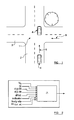
- a car 4 is travelling along the first road 2 towards the intersection 1, but has not yet reached the intersection 1.
- the direction of travel of the car is indicated in figure 1 by an arrow 5.
- the vehicle 4 crosses the intersection 1, and during the crossing of the intersection 1 the vehicle 4 will be positioned near the point at which vehicles approaching the intersection along the second road 3 will enter the intersection 1.
- the direction of travel along which some vehicles will enter the intersection 1 along the second road 2 is shown in figure 1 by an arrow 6.
- the vehicle 4 is provided with a number of sensors which are adapted to sense position, movement and control of the vehicle 4.
- the sensors may include a set of accelerometers to measure acceleration of the vehicle in the longitudinal, lateral and vertical directions, and the speed of the vehicle 4 in various directions can also be determined from outputs of these accelerometers.
- the accelerometers may also include a yaw sensor, to mention the yaw rate of the vehicle.
- a GPS or other positioning system is provided to determine the position of the vehicle on the Earth's surface. Sensors are further provided to detect use of the vehicle's indicators, the angle of the steering wheel, the angle of the throttle pedal, and the brake pressure that is applied to the brake pedal of the vehicle 4.
- the vehicle 4 also comprises one or more imaging devices, which may for example comprise a camera or a radar/lidar system, to form images of the surroundings of the vehicle 4.
- Side impact sensors are mounted along the sides of the vehicle 4, and are each configured to output a signal which is indicative of the lateral acceleration of the sensor.
- the vehicle 4 also comprises one or more safety devices, such as a side air-bag, to protect a vehicle occupant in the event of a side impact.
- the control unit which comprises one or more processors, interprets signals output by the various sensors and determines whether the safety devices should be triggered.
- the GPS or other positioning system is provided in conjunction with a map, which includes details of the locations of various intersections.
- the appropriate map data may be stored in an on-board memory unit, but may also be received continuously, or updated, by a transmission which is received by the vehicle 4.
- intersections are generally encountered in urban-type environments, and output from the sensors may be used to determine whether the vehicle is in such an environment.
- Urban driving is generally characterised by particular ranges of throttle rate, braking pressure rate, speed variation, use of indicators, steering wheel angle and change of steering wheel angle, and using information relating to some or all of these quantities it is possible to make a determination as to whether the vehicle is in an urban environment.
- a determination that the vehicle is in an urban environment, or crossing an intersection, will not be made if it is determined that the vehicle is understeering or oversteering, or that body slip (i.e. a lateral skid) of the vehicle is occurring. If any of these situations appear to be the case, the likelihood is that the vehicle is not traversing an intersection.
- a determination that the vehicle is in an urban environment, and/or crossing an intersection may be reached only if the speed of the vehicle falls within a range which is indicative of urban driving. For instance, such a determination will only be made if the speed of the vehicle is below 40 km an hour.
- a lower speed threshold is around 2 to 5 km an hour, with the upper speed threshold being around 30 to 40 km an hour.
- Vehicle safety systems embodying the present invention comprise a default deployment algorithm which is adapted to interpret data from the various vehicle sensors and to make a determination as to whether one or more safety devices should be deployed to protect an occupants of the vehicle from a side impact. Depending on the type of a particular safety device, the algorithm may also determine the mode in which the safety device is activated. This default deployment algorithm may be similar to conventional deployment algorithms.
- the vehicle's control unit also comprises at least one further deployment algorithm, which is used when it is determined that the likelihood of the vehicles being involved in a harmful side impact is high.
- the rate of lateral acceleration of the sensor is generally taken into account in determining the severity of a side impact. This lateral acceleration will be compared against a threshold, and one or more safety systems will be deployed if the lateral acceleration exceeds a preset threshold.
- this threshold must be set so that the safety systems will not be triggered by any inappropriate events, for instance the violent slamming of the door of the vehicle, or a low impact crash that is unlikely to cause harm to any occupants of the vehicle.
- a further deployment algorithm may be used by the vehicles control unit.
- the threshold of sideways acceleration of an impact sensor that must be met in order for the safety system to be triggered is lowered.
- the further deployment algorithm is adopted in situations where it is determined that the vehicle is traversing an intersection, or is about to traverse an intersection.
- this determination is made with reference to a combination of data received from the vehicle's positioning system, and stored map data.
- data from the one or more imaging devices may be used to recognise that the vehicle 4 is traversing or approaching an intersection, and a skilled person will appreciate how this may be achieved.
- images gathered may be compared against templates derived from stored images taken as a vehicles traverses or approaches an intersection.
- Data relating to the movement and/or control of the vehicle 4 may also be used, as an alternative to, or in conjunction with, the techniques described above.
- FIG 2 a schematic view of a decision-making process to decide which deployment algorithm to employ is shown.
- the vehicle's control unit comprises an intersection evaluation unit 7, which receives input relating to the longitudinal speed of the vehicle V x , the steering wheel angle ⁇ , the rate of change of the steering wheel angle, d ⁇ /dt, the rate of change d ⁇ /dt of the throttle angle ⁇ , the rate of change dP/dt of the brake pressure, information relating to the use of the vehicle's indicators, and information relating to the likelihood (as determined by vehicle sensors) of the vehicle 4 undergoing a body slip, understeer, or oversteer situations.
- this information will be analysed by the intersection evaluation unit 7, which will make a determination as to whether it is likely that the vehicle is traversing an intersection, or is about to traverse an intersection. In preferred embodiments, this will be achieved by analysing the information to determine whether the behaviour of the vehicle corresponds to typical urban driving.
- the threshold against which the lateral acceleration experienced by a side-mounted impact sensor is compared is lowered so that in effect the further deployment algorithm is more sensitive to potential side impacts, with the result that safety systems will be activated at an earlier stage in the event of a real side impact.
- the further deployment algorithm is made more sensitive to potential side impacts by reducing the threshold against which the lateral acceleration of a side impacts sensor is compared.
- the invention is not limited to this, and any appropriate threshold or criterion for assessing the likelihood that a side impact is occurring, or is likely to occur, may be reduced or adapted to make the further deployment algorithm more sensitive to side impacts.
- the further deployment algorithm will be employed.
- intersection described above is the crossing of two roads substantially at right angles to one another.
- an intersection may comprise any junction at which vehicles may approach one another non-parallel directions.
- Further examples include roundabouts, T-junctions and points at which slip-roads meet more major roads, although of course the invention is not limited to these examples.
- side impacts it will be understood that there are other types of impacts whose likelihood of occurence is increased if the lane in which a vehicle is travelling crosses or merges with another driving lane. These types of impact include front/side and rear/side impacts.
- embodiments of the present invention will provide a flexible system for triggering side-impact safety systems in the most appropriate manner depending on the circumstances, which may lead to a significant improvement in passenger safety.
Landscapes
- Engineering & Computer Science (AREA)
- Mechanical Engineering (AREA)
- Traffic Control Systems (AREA)
Description
- THIS INVENTION relates to a vehicle safety system, and in particular concerns a system for protecting vehicle occupants during various types of crash situation.
- Most vehicles are typically equipped with safety devices to protect vehicle occupants in the event of a side impact occurring. In general, in a sideways direction the distance between a vehicle occupant and the exterior of the vehicle is relatively small, since the sides of the vehicle are thin. It is therefore important that safety devices, such as internal side air-bags, which are adapted to protect occupants during side impacts, are activated at the earliest possible stage.
-
WO2005/118348 discloses a safety system for vehicle occupants according to the preambles ofclaims 1 and 10, having sensors for acquiring crash-relevant data such as acceleration and/or pressure values, having a control device, and having restraints, such as an air bag, safety belt, or the like. Thesafety system 1 has a connection to a navigation system of the vehicle. Data of the navigation system of the vehicle, such as in particular location data of the vehicle, are supplied to the safety system and are taken into account in a triggering decision for restraint. -
US2006267748 discloses a method for preventing collisions of vehicles, in which first the surroundings of a vehicle and motion parameters of the vehicle are detected by means of sensors. From the output signals of the sensors, a failure-to-yield criterion and a collision risk criterion are derived. From a combination of the failure-to-yield criterion and the collision risk criterion, a risk level is ascertained. Depending on the particular risk level ascertained, finally, steps for reducing the risk of collision are initiated. - In some instances, it is possible to detect that a side impact is imminent, for instance by using radar or lidar detection, and to activate one or more appropriate vehicle safety systems before the impact has occurred. In other circumstances, impact sensors are used to detect side impacts, and hence deployment of the vehicle safety systems will not occur until the impact has actually happened.
- Deployment of the safety systems will be controlled by an on-board processor, in accordance with a deployment algorithm. There are, however, competing priorities which must be taken into account when formulating the algorithm. On the one hand, as discussed above, the relevant side impact safety systems must be activated as swiftly as possible in the event of a crash situation occurring. On the other hand, the algorithm must be robust against "false positive" determinations, which could lead to the side impact safety systems being deployed unnecessarily. Such situations may include the door of a vehicle being slammed with above average force, and low-impact crashes that are unlikely to cause harm to vehicle occupants. It will therefore be understood that deployment algorithms are generally a compromise between these two competing priorities.
- It is an object of the present invention to seek to provide an improved safety system of this type.
- Accordingly, one aspect of the present invention provides a vehicle safety system comprising: at least one occupant safety device for protecting an occupant of the vehicle in the event of an impact of a predetermined type; and a control unit operable to receive information from one or more vehicle sensors and to provide a trigger signal to activate the occupant safety device, wherein: under normal driving conditions, a default deployment algorithm is used by the control unit to determine whether the trigger signal should be generated; and if it is determined that the vehicle is entering or crossing another driving lane, or is about to do so, the control unit employs a further deployment algorithm to determine whether the trigger signal should be generated, the further deployment algorithm being adapted to cause the trigger signal to be generated a shorter time after the initiation of an impact of the predetermined type than is the case for the default deployment algorithm; the sensors include sensors for measuring movement and/or control of the vehicle, and the control unit is operable to make a determination, from data output from these sensors, as to whether the vehicle is entering or crossing another driving lane, or is about to do so; the sensors operable to detect at least one of steering wheel angle, longitudinal speed, throttle angle, brake pressure and indicator status, or are able to determine whether the vehicle is involved in an understeer, oversteer or body slip situation; a determination will not be made that the vehicle is entering or crossing another driving lane if it is determined that the vehicle is undergoing an oversteer, understeer or body slip situation.
- Advantageously, the occupant safety device is for protecting an occupant in the event of a side impact.
- Preferably, the further deployment algorithm is employed if it is determined that the other driving lane crosses the driving lane along which the vehicle is travelling, or if it is determined that the driving lane along which the vehicle is travelling is entering the other driving lane.
- Conveniently, the vehicle sensors include a positioning system, and, the positioning system is provided in conjunction with stored map data which contains information relating to the location of one or more mergings or crossing of driving lanes.
- Preferably, the sensors include an imaging device, and the control unit is operable to recognise, from the data gathered by the imaging device, that the vehicle is entering or crossing another driving lane, or is about to do so, and the imaging device preferably comprises a camera.
- Preferably, it will only be determined that the vehicle is entering or crossing another driving lane, or is about to do so, if the longitudinal speed of the vehicle is between upper and lower speed thresholds.
- Advantageously, the lower speed threshold is about 5 to 10 km an hour, or the upper speed threshold is about 40 to 70 km an hour, or the upper speed threshold is about 50 km an hour.
- Advantageously, the trigger signal is generated if a preset threshold is exceeded by a parameter derived from the impact sensor, the threshold being lowered or adapted in the further deployment algorithm, when compared to the default deployment algorithm, so that the further deployment algorithm is more sensitive to impacts.
- Preferably, the impact sensor is an accelerometer, and the parameter derived from the sensor is integrated acceleration of the sensor.
- Another aspect of the present invention provides a method of controlling an occupant safety device of a vehicle for protecting an occupant of the vehicle in the event of an impact of a predetermined type, the method comprising the steps of: receiving information from one or more vehicle sensors; and analysing the signals in accordance with a deployment algorithm and providing a trigger signal to activate the occupant safety device if it is determined that activation of the safety device is necessary, wherein: under normal driving conditions, a default deployment algorithm is employed to determine whether the trigger signal should be generated; and if it is determined that the vehicle is entering or crossing another driving lane, or is about to do so, employing a further deployment algorithm to determine whether the trigger signal should be generated, the further deployment algorithm being adapted to cause the trigger signal to be generated a shorter time after the initiation of an impact of the predetermined type than is the case for the default deployment algorithm; providing sensors for measuring movement and/or control of the vehicle, and a control unit is operable to make a determination, from data output from these sensors, as to whether the vehicle is entering or crossing another driving lane, or is about to do so; the sensors operable to detect at least one of steering wheel angle, longitudinal speed, throttle angle, brake pressure and indicator status, or are able to determine whether the vehicle is involved in an understeer, oversteer or body slip situation; the step of determining will not be made that the vehicle is entering or crossing another driving lane if it is determined that the vehicle is undergoing an oversteer, understeer or body slip situation.
- A further aspect of the present invention provides a computer program comprising computer program code adapted to perform all of the above steps when the program is run on a computer.
- Another aspect of the present invention provides a computer program according to the above, embodied on a computer readable medium.
- In order that the present invention may be more readily understood, embodiments thereof will now be described, by way of example, with reference to the accompanying drawings, in which:
-
Figure 1 is a schematic view of a vehicle in an urban environment; and -
Figure 2 is a schematic view of components of a decision-making process for use with the systems embodying the present invention. - Referring firstly to
figure 1 , anintersection 1 between afirst road 2 and asecond road 3, which cross one another substantially at right angles, is shown. Theintersection 1 may be of any type, and the flow of traffic may be determined by one or more traffic lights or other signals, one of theroads roads intersection 1 from any direction may simply be allowed to cross theintersection 1 when they deem it safe to proceed. - A
car 4, is travelling along thefirst road 2 towards theintersection 1, but has not yet reached theintersection 1. The direction of travel of the car is indicated infigure 1 by an arrow 5. - At a later time, the
vehicle 4 crosses theintersection 1, and during the crossing of theintersection 1 thevehicle 4 will be positioned near the point at which vehicles approaching the intersection along thesecond road 3 will enter theintersection 1. The direction of travel along which some vehicles will enter theintersection 1 along thesecond road 2 is shown infigure 1 by anarrow 6. - As is known in the art, the
vehicle 4 is provided with a number of sensors which are adapted to sense position, movement and control of thevehicle 4. The sensors may include a set of accelerometers to mesure acceleration of the vehicle in the longitudinal, lateral and vertical directions, and the speed of thevehicle 4 in various directions can also be determined from outputs of these accelerometers. The accelerometers may also include a yaw sensor, to mention the yaw rate of the vehicle. A GPS or other positioning system is provided to determine the position of the vehicle on the Earth's surface. Sensors are further provided to detect use of the vehicle's indicators, the angle of the steering wheel, the angle of the throttle pedal, and the brake pressure that is applied to the brake pedal of thevehicle 4. thevehicle 4 also comprises one or more imaging devices, which may for example comprise a camera or a radar/lidar system, to form images of the surroundings of thevehicle 4. - Side impact sensors are mounted along the sides of the
vehicle 4, and are each configured to output a signal which is indicative of the lateral acceleration of the sensor. - The
vehicle 4 also comprises one or more safety devices, such as a side air-bag, to protect a vehicle occupant in the event of a side impact. The control unit, which comprises one or more processors, interprets signals output by the various sensors and determines whether the safety devices should be triggered. - Research shows that, when a vehicle is traversing an intersection, the likelihood of a harmful side impact occurring is relatively high. It will be understood that this is because the vehicle presents one or both of its side surfaces to the normal direction of travel of other vehicles, which may be travelling at significant speed as they enter the intersection.
- Using the information derived from some or all of the sensors of the
vehicle 4, it is possible to make a determination as to whether thevehicle 4 is traversing an intersection. - In preferred embodiments of the invention, the GPS or other positioning system is provided in conjunction with a map, which includes details of the locations of various intersections. The appropriate map data may be stored in an on-board memory unit, but may also be received continuously, or updated, by a transmission which is received by the
vehicle 4. - It will be understood that, by comparing the position of the
vehicle 4 as determined by the positioning system, with the map data, it will be possible to determine that thevehicle 4 is traversing an intersection, or is about to do so. - Alternatively, or in conjunction with the technique described above, it is possible to make a determination as to whether the
vehicle 4 is traversing an intersection from the sensed movement and control of the vehicle. For instance, intersections are generally encountered in urban-type environments, and output from the sensors may be used to determine whether the vehicle is in such an environment. Urban driving is generally characterised by particular ranges of throttle rate, braking pressure rate, speed variation, use of indicators, steering wheel angle and change of steering wheel angle, and using information relating to some or all of these quantities it is possible to make a determination as to whether the vehicle is in an urban environment. - A determination that the vehicle is in an urban environment, or crossing an intersection, will not be made if it is determined that the vehicle is understeering or oversteering, or that body slip (i.e. a lateral skid) of the vehicle is occurring. If any of these situations appear to be the case, the likelihood is that the vehicle is not traversing an intersection.
- Further, a determination that the vehicle is in an urban environment, and/or crossing an intersection, may be reached only if the speed of the vehicle falls within a range which is indicative of urban driving. For instance, such a determination will only be made if the speed of the vehicle is below 40 km an hour. In more preferred embodiments, a lower speed threshold is around 2 to 5 km an hour, with the upper speed threshold being around 30 to 40 km an hour.
- Vehicle safety systems embodying the present invention comprise a default deployment algorithm which is adapted to interpret data from the various vehicle sensors and to make a determination as to whether one or more safety devices should be deployed to protect an occupants of the vehicle from a side impact. Depending on the type of a particular safety device, the algorithm may also determine the mode in which the safety device is activated. This default deployment algorithm may be similar to conventional deployment algorithms.
- The vehicle's control unit also comprises at least one further deployment algorithm, which is used when it is determined that the likelihood of the vehicles being involved in a harmful side impact is high.
- When a safety system is deployed in accordance with a deployment algorithm which uses information from impact sensors which are mounted at the side of a vehicle, the rate of lateral acceleration of the sensor is generally taken into account in determining the severity of a side impact. This lateral acceleration will be compared against a threshold, and one or more safety systems will be deployed if the lateral acceleration exceeds a preset threshold.
- As described above, this threshold must be set so that the safety systems will not be triggered by any inappropriate events, for instance the violent slamming of the door of the vehicle, or a low impact crash that is unlikely to cause harm to any occupants of the vehicle.
- Shortly after the initiation of a crash (for example, after a few milliseconds) it is difficult to discriminate the output of an impact sensor from a real crash from the sensor output from a less serious event (such as the slamming of a door of the vehicle, or a hammer blow), or the impact of light objects, such as pedestrians or cyclists, because the integrated acceleration of a side impact sensor for all of these cases would be of roughly of the same magnitude. In the latter cases, safety devices to protect occupants should not be activated, and to avoid the accidental activation of these systems deployment algorithms generally wait until a later time, at which the integrated acceleration from a serious impact will be relatively easy to distinguish from the integrated acceleration arising from a less serious event.
- It will be appreciated, however, that delaying the activation of safety devices in the event of a real crash is undesirable.
- If it is determined that, however, that the
vehicle 4 is in a situation where a harmful side impact appears to be likely, it is possible to lower the threshold against which the lateral acceleration of an impact sensor is compared, as the benefit obtained from early triggering of safety system will outweigh the potential risk of the safety systems being triggered erroneously. - Referring again to
figure 1 , if thevehicle 4 is traversing the intersection I, there is a relatively high risk that another vehicle will enter theintersection 1 whilst travelling along on thesecond road 3, and strike a side surface of thevehicle 4. - Under these circumstance, the risk of events such as the slamming of a door of the vehicle, which might lead to a erroneous triggering of the safety systems, is very small.
- Under such circumstances, therefore, a further deployment algorithm may be used by the vehicles control unit. When the further deployment algorithm is used, the threshold of sideways acceleration of an impact sensor that must be met in order for the safety system to be triggered is lowered.
- In preferred embodiments of the invention, the further deployment algorithm is adopted in situations where it is determined that the vehicle is traversing an intersection, or is about to traverse an intersection.
- As described above, in preferred embodiments this determination is made with reference to a combination of data received from the vehicle's positioning system, and stored map data.
- Alternatively, or in conjunction, data from the one or more imaging devices may be used to recognise that the
vehicle 4 is traversing or approaching an intersection, and a skilled person will appreciate how this may be achieved. For example, images gathered may be compared against templates derived from stored images taken as a vehicles traverses or approaches an intersection. - Data relating to the movement and/or control of the
vehicle 4 may also be used, as an alternative to, or in conjunction with, the techniques described above. With reference tofigure 2 , a schematic view of a decision-making process to decide which deployment algorithm to employ is shown. - The vehicle's control unit comprises an
intersection evaluation unit 7, which receives input relating to the longitudinal speed of the vehicle Vx, the steering wheel angle α, the rate of change of the steering wheel angle, dα/dt, the rate of change dβ/dt of the throttle angle α, the rate of change dP/dt of the brake pressure, information relating to the use of the vehicle's indicators, and information relating to the likelihood (as determined by vehicle sensors) of thevehicle 4 undergoing a body slip, understeer, or oversteer situations. - As described above, this information will be analysed by the
intersection evaluation unit 7, which will make a determination as to whether it is likely that the vehicle is traversing an intersection, or is about to traverse an intersection. In preferred embodiments, this will be achieved by analysing the information to determine whether the behaviour of the vehicle corresponds to typical urban driving. - As discussed above, when the further deployment algorithm is used, the threshold against which the lateral acceleration experienced by a side-mounted impact sensor is compared is lowered so that in effect the further deployment algorithm is more sensitive to potential side impacts, with the result that safety systems will be activated at an earlier stage in the event of a real side impact.
- If it is determined that the
vehicle 4 is traversing, or is about to traverse, an intersection, but no side impact occurs and thevehicle 4 continues to a stage where it no longer appears likely that the vehicle is in the vicinity of an intersection, the conditions described above will no longer be met, and it will be determined that thevehicle 4 is no longer in a situation where a harmful side impact is likely. In this case, the default deployment algorithm for side impact safety systems will once again be used. - In the embodiments described above, the further deployment algorithm is made more sensitive to potential side impacts by reducing the threshold against which the lateral acceleration of a side impacts sensor is compared. However, the invention is not limited to this, and any appropriate threshold or criterion for assessing the likelihood that a side impact is occurring, or is likely to occur, may be reduced or adapted to make the further deployment algorithm more sensitive to side impacts. In general, when it is determined that the vehicle is entering a crossing and not a driving lane, or is about to do so, the further deployment algorithm will be employed.
- The intersection described above is the crossing of two roads substantially at right angles to one another. However, it should be appreciated that an intersection may comprise any junction at which vehicles may approach one another non-parallel directions. Further examples include roundabouts, T-junctions and points at which slip-roads meet more major roads, although of course the invention is not limited to these examples. Whilst the above discussion is directed primarily to side impacts, it will be understood that there are other types of impacts whose likelihood of occurence is increased if the lane in which a vehicle is travelling crosses or merges with another driving lane. These types of impact include front/side and rear/side impacts.
- It will be understood that embodiments of the present invention will provide a flexible system for triggering side-impact safety systems in the most appropriate manner depending on the circumstances, which may lead to a significant improvement in passenger safety.
- When used in this specification and claims, the terms "comprises" and "comprising" and variations thereof mean that the specified features, steps or integers arc included. The terms are not to be interpreted to exclude the presence of other features, steps or components.
Claims (12)
- A vehicle safety system comprising:at least one occupant safety device for protecting an occupant of the vehicle (4) in the event of an impact of a predetermined type; anda control unit operable to receive information from one or more vehicle sensors and to provide a trigger signal to activate the occupant safety device, wherein:under normal driving conditions, a default deployment algorithm is used by the control unit to determine whether the trigger signal should be generated; andif it is determined that the vehicle is entering or crossing another driving lane (3), or is about to do so, the control unit employs a further deployment algorithm to determine whether the trigger signal should be generated, the further deployment algorithm being adapted to cause the trigger signal to be generated a shorter time after the initiation of an impact of the predetermined type than is the case for the default deployment algorithm; the sensors include sensors for measuring movement and/or control of the vehicle (4), and the control unit is operable to make a determination, from data output from these sensors, as to whether the vehicle (4) is entering or crossing another driving lane (3), or is about to do so; the sensors operable to detect at least one of steering wheel angle, longitudinal speed, throttle angle, brake pressure and indicator status, or are able to determine whether the vehicle (4) is involved in an understeer, oversteer or body slip situation; characterised in that a determination will not be made that the vehicle (4) is entering or crossing another driving lane (3) if it is determined that the vehicle (4) is undergoing an oversteer, understeer or body slip situation.
- A system according to claim 1, wherein the occupant safety device is for protecting an occupant in the event of a side impact.
- A system according to claim 1 or 2, wherein the further deployment algorithm is employed if it is determined the other driving lane (3) crosses the driving lane (2) along which the vehicle (1) is travelling, or if it is determined that the driving lane (2) along which the vehicle is travelling is entering the other driving lane (3).
- A system according to any preceding claims, in which the vehicle sensors include a positioning system, and the positioning system is preferably provided in conjunction with stored map data which contains information relating to the location of one or more mergings or crossing of driving lanes (2,3).
- A system according to any preceding claim, wherein the sensors include an imaging device, and the control unit is operable to recognise, from data gathered by the imaging device, that the vehicle is entering or crossing another driving lane (3), or is about to do so, and the imaging device preferably comprises a camera.
- A system according to claim 1, wherein it will only be determined that the vehicle is entering or crossing another driving lane (3), or is about to do so, if the longitudinal speed (5) of the vehicle is between upper and lower speed thresholds.
- A system according to claim 6, wherein the lower speed threshold is about 5 to 10 km an hour, or the upper speed threshold is about 40 to 70 km an hour, or is about 50 km an hour.
- A system according to any preceding claim, wherein the trigger signal is generated if a preset threshold is exceeded by a parameter derived from the impact sensor, the threshold being lowered or adapted in the further deployment algorithm, when compared to the default deployment algorithm, so that the further deployment algorithm is more sensitive to impacts.
- A system according to claim 8, wherein the impact sensor is an accelerometer, and the parameter derived from the sensor is integrated acceleration of the sensor.
- A method of controlling an occupant safety device of a vehicle (4) for protecting an occupant of the vehicle (4) in the event of an impact of a predetermined type, the method comprising the steps of:receiving information from one or more vehicle sensors; andanalysing the signals in accordance with a deployment algorithm and providing a trigger signal to activate the occupant safety device if it is determined that activation of the safety device is necessary, wherein:under normal driving conditions, a default deployment algorithm is employed to determine whether the trigger signal should be generated;if it is determined that the vehicle is entering or crossing another driving lane (3), or is about to do so, employing a further deployment algorithm to determine whether the trigger signal should be generated, the farther deployment algorithm being adapted to cause the trigger signal to be generated a shorter time after the initiation of an impact of the predetermined type than is the case for the default deployment algorithm; providing sensors for measuring movement and/or control of the vehicle (4), and a control unit is operable to make a determination, from data output from these sensors, as to whether the vehicle (4) is entering or crossing another driving lane (3), or is about to do so; the sensors operable to detect at least one of steering wheel angle, longitudinal speed, throttle angle, brake pressure and indicator status, or are able to determine whether the vehicle (4) is involved in an understeer, oversteer or body slip situation; characterised in that the step of determining will not be made that the vehicle (4) is entering or crossing another driving lane (3) if it is determined that the vehicle (4) is undergoing an oversteer, understeer or body slip situation.
- A computer program comprising computer program code adapted to perform all of the steps of claim 10 when the program is ran on a computer.
- A computer program according to claim 11, embodied on a computer readable medium.
Applications Claiming Priority (1)
| Application Number | Priority Date | Filing Date | Title |
|---|---|---|---|
| PCT/SE2008/050095 WO2009096827A1 (en) | 2008-01-28 | 2008-01-28 | A vehicle safety system |
Publications (3)
| Publication Number | Publication Date |
|---|---|
| EP2234845A1 EP2234845A1 (en) | 2010-10-06 |
| EP2234845A4 EP2234845A4 (en) | 2012-03-14 |
| EP2234845B1 true EP2234845B1 (en) | 2013-08-21 |
Family
ID=40913019
Family Applications (1)
| Application Number | Title | Priority Date | Filing Date |
|---|---|---|---|
| EP08705367.4A Not-in-force EP2234845B1 (en) | 2008-01-28 | 2008-01-28 | A vehicle safety system |
Country Status (2)
| Country | Link |
|---|---|
| EP (1) | EP2234845B1 (en) |
| WO (1) | WO2009096827A1 (en) |
Families Citing this family (2)
| Publication number | Priority date | Publication date | Assignee | Title |
|---|---|---|---|---|
| EP3095647B1 (en) * | 2015-05-19 | 2017-05-17 | Autoliv Development AB | Adapting safety mechanisms of a vehicle safety system |
| JP6749417B2 (en) | 2016-12-20 | 2020-09-02 | パイオニア株式会社 | Accident determination device |
Family Cites Families (3)
| Publication number | Priority date | Publication date | Assignee | Title |
|---|---|---|---|---|
| DE10244205A1 (en) | 2002-09-23 | 2004-03-25 | Robert Bosch Gmbh | Vehicle collision prevention method for preventing collision between motor vehicles uses sensors to detect a vehicle's surroundings and its amount of movement |
| DE102004027206A1 (en) | 2004-06-03 | 2005-12-22 | Robert Bosch Gmbh | Security system for vehicle occupants |
| JP4918503B2 (en) * | 2005-02-18 | 2012-04-18 | シーメンス・ブイディーオー・オートモーティブ・コーポレイション | Validity of side impact using lateral velocity |
-
2008
- 2008-01-28 EP EP08705367.4A patent/EP2234845B1/en not_active Not-in-force
- 2008-01-28 WO PCT/SE2008/050095 patent/WO2009096827A1/en not_active Ceased
Also Published As
| Publication number | Publication date |
|---|---|
| EP2234845A4 (en) | 2012-03-14 |
| WO2009096827A1 (en) | 2009-08-06 |
| EP2234845A1 (en) | 2010-10-06 |
Similar Documents
| Publication | Publication Date | Title |
|---|---|---|
| JP7645668B2 (en) | Vehicle safety system and method for performing weighted active-passive crash mode classification - Patents.com | |
| CN105813903B (en) | Vehicle security system | |
| CN101678819B (en) | Collision reducing device | |
| CN106256613B (en) | Method, device and safety system for controlling the triggering of a vehicle occupant protection device | |
| US6796397B2 (en) | Method of activating a passenger safety application in a motor vehicle | |
| US20180178745A1 (en) | Method and device in a motor vehicle for protecting pedestrians | |
| US20060058964A1 (en) | Method and device for triggering emergency braking | |
| CN113386698B (en) | Vehicle safety systems implementing integrated active-passive frontal collision control algorithms | |
| CN109923004B (en) | Method for controlling personal protection means | |
| WO2008002756A2 (en) | Rear collision warning system | |
| EP2234844B1 (en) | A vehicle safety system | |
| KR20090068253A (en) | Vehicle safety systems | |
| CN107921960A (en) | Safety means for vehicle | |
| CN102639366A (en) | Method for activating and/or triggering at least one reversible restraint device | |
| CN107627983A (en) | Method and control device for the passenger protection system of operating and controlling vehicle | |
| CN103373350B (en) | Large animal vehicle collision safety apparatus and method | |
| CN113677566A (en) | Low impact detection for autonomous vehicles | |
| EP2234845A1 (en) | A vehicle safety system | |
| JP2006525913A (en) | Safety system for vehicle occupants | |
| CN102039866A (en) | Device for operating motor vehicle | |
| KR101596995B1 (en) | Impact absorption method for vehicles |
Legal Events
| Date | Code | Title | Description |
|---|---|---|---|
| PUAI | Public reference made under article 153(3) epc to a published international application that has entered the european phase |
Free format text: ORIGINAL CODE: 0009012 |
|
| 17P | Request for examination filed |
Effective date: 20100331 |
|
| AK | Designated contracting states |
Kind code of ref document: A1 Designated state(s): AT BE BG CH CY CZ DE DK EE ES FI FR GB GR HR HU IE IS IT LI LT LU LV MC MT NL NO PL PT RO SE SI SK TR |
|
| AX | Request for extension of the european patent |
Extension state: AL BA MK RS |
|
| DAX | Request for extension of the european patent (deleted) | ||
| A4 | Supplementary search report drawn up and despatched |
Effective date: 20120209 |
|
| RIC1 | Information provided on ipc code assigned before grant |
Ipc: B60R 21/013 20060101AFI20120203BHEP |
|
| GRAP | Despatch of communication of intention to grant a patent |
Free format text: ORIGINAL CODE: EPIDOSNIGR1 |
|
| INTG | Intention to grant announced |
Effective date: 20130531 |
|
| GRAS | Grant fee paid |
Free format text: ORIGINAL CODE: EPIDOSNIGR3 |
|
| GRAA | (expected) grant |
Free format text: ORIGINAL CODE: 0009210 |
|
| AK | Designated contracting states |
Kind code of ref document: B1 Designated state(s): AT BE BG CH CY CZ DE DK EE ES FI FR GB GR HR HU IE IS IT LI LT LU LV MC MT NL NO PL PT RO SE SI SK TR |
|
| REG | Reference to a national code |
Ref country code: GB Ref legal event code: FG4D |
|
| REG | Reference to a national code |
Ref country code: CH Ref legal event code: EP |
|
| REG | Reference to a national code |
Ref country code: AT Ref legal event code: REF Ref document number: 627852 Country of ref document: AT Kind code of ref document: T Effective date: 20130915 |
|
| REG | Reference to a national code |
Ref country code: IE Ref legal event code: FG4D |
|
| REG | Reference to a national code |
Ref country code: DE Ref legal event code: R096 Ref document number: 602008026945 Country of ref document: DE Effective date: 20131017 |
|
| REG | Reference to a national code |
Ref country code: AT Ref legal event code: MK05 Ref document number: 627852 Country of ref document: AT Kind code of ref document: T Effective date: 20130821 Ref country code: NL Ref legal event code: VDEP Effective date: 20130821 |
|
| REG | Reference to a national code |
Ref country code: LT Ref legal event code: MG4D |
|
| PG25 | Lapsed in a contracting state [announced via postgrant information from national office to epo] |
Ref country code: SE Free format text: LAPSE BECAUSE OF FAILURE TO SUBMIT A TRANSLATION OF THE DESCRIPTION OR TO PAY THE FEE WITHIN THE PRESCRIBED TIME-LIMIT Effective date: 20130821 Ref country code: PT Free format text: LAPSE BECAUSE OF FAILURE TO SUBMIT A TRANSLATION OF THE DESCRIPTION OR TO PAY THE FEE WITHIN THE PRESCRIBED TIME-LIMIT Effective date: 20131223 Ref country code: LT Free format text: LAPSE BECAUSE OF FAILURE TO SUBMIT A TRANSLATION OF THE DESCRIPTION OR TO PAY THE FEE WITHIN THE PRESCRIBED TIME-LIMIT Effective date: 20130821 Ref country code: HR Free format text: LAPSE BECAUSE OF FAILURE TO SUBMIT A TRANSLATION OF THE DESCRIPTION OR TO PAY THE FEE WITHIN THE PRESCRIBED TIME-LIMIT Effective date: 20130821 Ref country code: AT Free format text: LAPSE BECAUSE OF FAILURE TO SUBMIT A TRANSLATION OF THE DESCRIPTION OR TO PAY THE FEE WITHIN THE PRESCRIBED TIME-LIMIT Effective date: 20130821 Ref country code: IS Free format text: LAPSE BECAUSE OF FAILURE TO SUBMIT A TRANSLATION OF THE DESCRIPTION OR TO PAY THE FEE WITHIN THE PRESCRIBED TIME-LIMIT Effective date: 20131221 Ref country code: CY Free format text: LAPSE BECAUSE OF FAILURE TO SUBMIT A TRANSLATION OF THE DESCRIPTION OR TO PAY THE FEE WITHIN THE PRESCRIBED TIME-LIMIT Effective date: 20130911 Ref country code: NO Free format text: LAPSE BECAUSE OF FAILURE TO SUBMIT A TRANSLATION OF THE DESCRIPTION OR TO PAY THE FEE WITHIN THE PRESCRIBED TIME-LIMIT Effective date: 20131121 |
|
| PG25 | Lapsed in a contracting state [announced via postgrant information from national office to epo] |
Ref country code: SI Free format text: LAPSE BECAUSE OF FAILURE TO SUBMIT A TRANSLATION OF THE DESCRIPTION OR TO PAY THE FEE WITHIN THE PRESCRIBED TIME-LIMIT Effective date: 20130821 Ref country code: PL Free format text: LAPSE BECAUSE OF FAILURE TO SUBMIT A TRANSLATION OF THE DESCRIPTION OR TO PAY THE FEE WITHIN THE PRESCRIBED TIME-LIMIT Effective date: 20130821 Ref country code: BE Free format text: LAPSE BECAUSE OF FAILURE TO SUBMIT A TRANSLATION OF THE DESCRIPTION OR TO PAY THE FEE WITHIN THE PRESCRIBED TIME-LIMIT Effective date: 20130821 Ref country code: GR Free format text: LAPSE BECAUSE OF FAILURE TO SUBMIT A TRANSLATION OF THE DESCRIPTION OR TO PAY THE FEE WITHIN THE PRESCRIBED TIME-LIMIT Effective date: 20131122 Ref country code: LV Free format text: LAPSE BECAUSE OF FAILURE TO SUBMIT A TRANSLATION OF THE DESCRIPTION OR TO PAY THE FEE WITHIN THE PRESCRIBED TIME-LIMIT Effective date: 20130821 Ref country code: FI Free format text: LAPSE BECAUSE OF FAILURE TO SUBMIT A TRANSLATION OF THE DESCRIPTION OR TO PAY THE FEE WITHIN THE PRESCRIBED TIME-LIMIT Effective date: 20130821 |
|
| PG25 | Lapsed in a contracting state [announced via postgrant information from national office to epo] |
Ref country code: CY Free format text: LAPSE BECAUSE OF FAILURE TO SUBMIT A TRANSLATION OF THE DESCRIPTION OR TO PAY THE FEE WITHIN THE PRESCRIBED TIME-LIMIT Effective date: 20130821 |
|
| PG25 | Lapsed in a contracting state [announced via postgrant information from national office to epo] |
Ref country code: EE Free format text: LAPSE BECAUSE OF FAILURE TO SUBMIT A TRANSLATION OF THE DESCRIPTION OR TO PAY THE FEE WITHIN THE PRESCRIBED TIME-LIMIT Effective date: 20130821 Ref country code: NL Free format text: LAPSE BECAUSE OF FAILURE TO SUBMIT A TRANSLATION OF THE DESCRIPTION OR TO PAY THE FEE WITHIN THE PRESCRIBED TIME-LIMIT Effective date: 20130821 Ref country code: RO Free format text: LAPSE BECAUSE OF FAILURE TO SUBMIT A TRANSLATION OF THE DESCRIPTION OR TO PAY THE FEE WITHIN THE PRESCRIBED TIME-LIMIT Effective date: 20130821 Ref country code: SK Free format text: LAPSE BECAUSE OF FAILURE TO SUBMIT A TRANSLATION OF THE DESCRIPTION OR TO PAY THE FEE WITHIN THE PRESCRIBED TIME-LIMIT Effective date: 20130821 Ref country code: DK Free format text: LAPSE BECAUSE OF FAILURE TO SUBMIT A TRANSLATION OF THE DESCRIPTION OR TO PAY THE FEE WITHIN THE PRESCRIBED TIME-LIMIT Effective date: 20130821 Ref country code: CZ Free format text: LAPSE BECAUSE OF FAILURE TO SUBMIT A TRANSLATION OF THE DESCRIPTION OR TO PAY THE FEE WITHIN THE PRESCRIBED TIME-LIMIT Effective date: 20130821 |
|
| PG25 | Lapsed in a contracting state [announced via postgrant information from national office to epo] |
Ref country code: IT Free format text: LAPSE BECAUSE OF FAILURE TO SUBMIT A TRANSLATION OF THE DESCRIPTION OR TO PAY THE FEE WITHIN THE PRESCRIBED TIME-LIMIT Effective date: 20130821 Ref country code: ES Free format text: LAPSE BECAUSE OF FAILURE TO SUBMIT A TRANSLATION OF THE DESCRIPTION OR TO PAY THE FEE WITHIN THE PRESCRIBED TIME-LIMIT Effective date: 20130821 |
|
| PLBE | No opposition filed within time limit |
Free format text: ORIGINAL CODE: 0009261 |
|
| STAA | Information on the status of an ep patent application or granted ep patent |
Free format text: STATUS: NO OPPOSITION FILED WITHIN TIME LIMIT |
|
| 26N | No opposition filed |
Effective date: 20140522 |
|
| PG25 | Lapsed in a contracting state [announced via postgrant information from national office to epo] |
Ref country code: LU Free format text: LAPSE BECAUSE OF FAILURE TO SUBMIT A TRANSLATION OF THE DESCRIPTION OR TO PAY THE FEE WITHIN THE PRESCRIBED TIME-LIMIT Effective date: 20140128 Ref country code: MC Free format text: LAPSE BECAUSE OF FAILURE TO SUBMIT A TRANSLATION OF THE DESCRIPTION OR TO PAY THE FEE WITHIN THE PRESCRIBED TIME-LIMIT Effective date: 20130821 |
|
| REG | Reference to a national code |
Ref country code: CH Ref legal event code: PL |
|
| REG | Reference to a national code |
Ref country code: DE Ref legal event code: R097 Ref document number: 602008026945 Country of ref document: DE Effective date: 20140522 |
|
| PG25 | Lapsed in a contracting state [announced via postgrant information from national office to epo] |
Ref country code: CH Free format text: LAPSE BECAUSE OF NON-PAYMENT OF DUE FEES Effective date: 20140131 Ref country code: LI Free format text: LAPSE BECAUSE OF NON-PAYMENT OF DUE FEES Effective date: 20140131 |
|
| REG | Reference to a national code |
Ref country code: IE Ref legal event code: MM4A |
|
| PG25 | Lapsed in a contracting state [announced via postgrant information from national office to epo] |
Ref country code: IE Free format text: LAPSE BECAUSE OF NON-PAYMENT OF DUE FEES Effective date: 20140128 |
|
| REG | Reference to a national code |
Ref country code: FR Ref legal event code: PLFP Year of fee payment: 9 |
|
| PG25 | Lapsed in a contracting state [announced via postgrant information from national office to epo] |
Ref country code: MT Free format text: LAPSE BECAUSE OF FAILURE TO SUBMIT A TRANSLATION OF THE DESCRIPTION OR TO PAY THE FEE WITHIN THE PRESCRIBED TIME-LIMIT Effective date: 20130821 |
|
| PG25 | Lapsed in a contracting state [announced via postgrant information from national office to epo] |
Ref country code: BG Free format text: LAPSE BECAUSE OF FAILURE TO SUBMIT A TRANSLATION OF THE DESCRIPTION OR TO PAY THE FEE WITHIN THE PRESCRIBED TIME-LIMIT Effective date: 20130821 |
|
| PG25 | Lapsed in a contracting state [announced via postgrant information from national office to epo] |
Ref country code: HU Free format text: LAPSE BECAUSE OF FAILURE TO SUBMIT A TRANSLATION OF THE DESCRIPTION OR TO PAY THE FEE WITHIN THE PRESCRIBED TIME-LIMIT; INVALID AB INITIO Effective date: 20080128 Ref country code: TR Free format text: LAPSE BECAUSE OF FAILURE TO SUBMIT A TRANSLATION OF THE DESCRIPTION OR TO PAY THE FEE WITHIN THE PRESCRIBED TIME-LIMIT Effective date: 20130821 |
|
| REG | Reference to a national code |
Ref country code: FR Ref legal event code: PLFP Year of fee payment: 10 |
|
| REG | Reference to a national code |
Ref country code: FR Ref legal event code: PLFP Year of fee payment: 11 |
|
| REG | Reference to a national code |
Ref country code: GB Ref legal event code: 732E Free format text: REGISTERED BETWEEN 20190110 AND 20190116 |
|
| REG | Reference to a national code |
Ref country code: DE Ref legal event code: R081 Ref document number: 602008026945 Country of ref document: DE Owner name: VEONEER SWEDEN SAFETY SYSTEMS AB, SE Free format text: FORMER OWNERS: AUTOLIV DEVELOPMENT AB, VARGARDA, SE; FORD GLOBAL TECHNOLOGIES, LLC, DEARBORN, MICH., US Ref country code: DE Ref legal event code: R082 Ref document number: 602008026945 Country of ref document: DE Representative=s name: BOEHMERT & BOEHMERT ANWALTSPARTNERSCHAFT MBB -, DE Ref country code: DE Ref legal event code: R081 Ref document number: 602008026945 Country of ref document: DE Owner name: VEONEER SWEDEN AB, SE Free format text: FORMER OWNERS: AUTOLIV DEVELOPMENT AB, VARGARDA, SE; FORD GLOBAL TECHNOLOGIES, LLC, DEARBORN, MICH., US Ref country code: DE Ref legal event code: R081 Ref document number: 602008026945 Country of ref document: DE Owner name: FORD GLOBAL TECHNOLOGIES, LLC, DEARBORN, US Free format text: FORMER OWNERS: AUTOLIV DEVELOPMENT AB, VARGARDA, SE; FORD GLOBAL TECHNOLOGIES, LLC, DEARBORN, MICH., US |
|
| REG | Reference to a national code |
Ref country code: GB Ref legal event code: 732E Free format text: REGISTERED BETWEEN 20230511 AND 20230517 |
|
| REG | Reference to a national code |
Ref country code: DE Ref legal event code: R081 Ref document number: 602008026945 Country of ref document: DE Owner name: VEONEER SWEDEN SAFETY SYSTEMS AB, SE Free format text: FORMER OWNERS: FORD GLOBAL TECHNOLOGIES, LLC, DEARBORN, MICH., US; VEONEER SWEDEN AB, VARGARDA, SE Ref country code: DE Ref legal event code: R081 Ref document number: 602008026945 Country of ref document: DE Owner name: FORD GLOBAL TECHNOLOGIES, LLC, DEARBORN, US Free format text: FORMER OWNERS: FORD GLOBAL TECHNOLOGIES, LLC, DEARBORN, MICH., US; VEONEER SWEDEN AB, VARGARDA, SE |
|
| PGFP | Annual fee paid to national office [announced via postgrant information from national office to epo] |
Ref country code: GB Payment date: 20231215 Year of fee payment: 17 |
|
| PGFP | Annual fee paid to national office [announced via postgrant information from national office to epo] |
Ref country code: FR Payment date: 20231215 Year of fee payment: 17 |
|
| PGFP | Annual fee paid to national office [announced via postgrant information from national office to epo] |
Ref country code: DE Payment date: 20231218 Year of fee payment: 17 |
|
| REG | Reference to a national code |
Ref country code: DE Ref legal event code: R119 Ref document number: 602008026945 Country of ref document: DE |
|
| GBPC | Gb: european patent ceased through non-payment of renewal fee |
Effective date: 20250128 |
|
| PG25 | Lapsed in a contracting state [announced via postgrant information from national office to epo] |
Ref country code: DE Free format text: LAPSE BECAUSE OF NON-PAYMENT OF DUE FEES Effective date: 20250801 |
|
| PG25 | Lapsed in a contracting state [announced via postgrant information from national office to epo] |
Ref country code: GB Free format text: LAPSE BECAUSE OF NON-PAYMENT OF DUE FEES Effective date: 20250128 |
|
| PG25 | Lapsed in a contracting state [announced via postgrant information from national office to epo] |
Ref country code: FR Free format text: LAPSE BECAUSE OF NON-PAYMENT OF DUE FEES Effective date: 20250131 |