EP2234561B1 - A brushhead/handle interface for a power toothbrush - Google Patents
A brushhead/handle interface for a power toothbrush Download PDFInfo
- Publication number
- EP2234561B1 EP2234561B1 EP08862717A EP08862717A EP2234561B1 EP 2234561 B1 EP2234561 B1 EP 2234561B1 EP 08862717 A EP08862717 A EP 08862717A EP 08862717 A EP08862717 A EP 08862717A EP 2234561 B1 EP2234561 B1 EP 2234561B1
- Authority
- EP
- European Patent Office
- Prior art keywords
- driveshaft
- interface
- coupling member
- brushhead
- coupling
- Prior art date
- Legal status (The legal status is an assumption and is not a legal conclusion. Google has not performed a legal analysis and makes no representation as to the accuracy of the status listed.)
- Active
Links
- 230000008878 coupling Effects 0.000 claims abstract description 67
- 238000010168 coupling process Methods 0.000 claims abstract description 67
- 238000005859 coupling reaction Methods 0.000 claims abstract description 67
- 230000014759 maintenance of location Effects 0.000 claims abstract description 15
- 238000004140 cleaning Methods 0.000 claims abstract description 7
- 230000000593 degrading effect Effects 0.000 claims description 2
- 230000003993 interaction Effects 0.000 description 3
- 238000005299 abrasion Methods 0.000 description 1
- DHKHKXVYLBGOIT-UHFFFAOYSA-N acetaldehyde Diethyl Acetal Natural products CCOC(C)OCC DHKHKXVYLBGOIT-UHFFFAOYSA-N 0.000 description 1
- 125000002777 acetyl group Chemical class [H]C([H])([H])C(*)=O 0.000 description 1
- 239000003086 colorant Substances 0.000 description 1
- 230000006835 compression Effects 0.000 description 1
- 238000007906 compression Methods 0.000 description 1
- 230000013011 mating Effects 0.000 description 1
- 230000007246 mechanism Effects 0.000 description 1
- 230000004048 modification Effects 0.000 description 1
- 238000012986 modification Methods 0.000 description 1
- 230000010355 oscillation Effects 0.000 description 1
- 230000010399 physical interaction Effects 0.000 description 1
- 238000005488 sandblasting Methods 0.000 description 1
- 238000006467 substitution reaction Methods 0.000 description 1
Images


Classifications
-
- A—HUMAN NECESSITIES
- A61—MEDICAL OR VETERINARY SCIENCE; HYGIENE
- A61C—DENTISTRY; APPARATUS OR METHODS FOR ORAL OR DENTAL HYGIENE
- A61C17/00—Devices for cleaning, polishing, rinsing or drying teeth, teeth cavities or prostheses; Saliva removers; Dental appliances for receiving spittle
- A61C17/16—Power-driven cleaning or polishing devices
- A61C17/22—Power-driven cleaning or polishing devices with brushes, cushions, cups, or the like
- A61C17/32—Power-driven cleaning or polishing devices with brushes, cushions, cups, or the like reciprocating or oscillating
- A61C17/34—Power-driven cleaning or polishing devices with brushes, cushions, cups, or the like reciprocating or oscillating driven by electric motor
-
- A—HUMAN NECESSITIES
- A61—MEDICAL OR VETERINARY SCIENCE; HYGIENE
- A61C—DENTISTRY; APPARATUS OR METHODS FOR ORAL OR DENTAL HYGIENE
- A61C17/00—Devices for cleaning, polishing, rinsing or drying teeth, teeth cavities or prostheses; Saliva removers; Dental appliances for receiving spittle
- A61C17/16—Power-driven cleaning or polishing devices
- A61C17/22—Power-driven cleaning or polishing devices with brushes, cushions, cups, or the like
- A61C17/222—Brush body details, e.g. the shape thereof or connection to handle
-
- A—HUMAN NECESSITIES
- A61—MEDICAL OR VETERINARY SCIENCE; HYGIENE
- A61C—DENTISTRY; APPARATUS OR METHODS FOR ORAL OR DENTAL HYGIENE
- A61C2201/00—Material properties
- A61C2201/002—Material properties using colour effect, e.g. for identification purposes
Definitions
- This invention relates generally to handle/brushhead interface arrangements for power toothbrushes, and more specifically concerns such an interface in which the torque transfer function and axial retention function of the brushhead relative to the toothbrush driveshaft is accomplished by a single spring and coupling combination.
- a driveshaft driven rotationally or through a selected angle of oscillation, extends from a handle portion of the toothbrush, with the drive mechanism being contained within the handle portion.
- a removable brushhead assembly fits onto the extending driveshaft.
- the brushhead assembly includes a coupling member, which fits into an arm portion of the brushhead assembly. At the distal end of the arm portion is a brush member for cleaning teeth.
- the driveshaft extends into and securely mates with the coupling member.
- the structural interaction between the drive shaft and the coupling member must be such as to reliably transfer the torque of the moving driveshaft to the brushhead and to maintain the torque transfer under load.
- the load refers to a combination of the torque created by the inertial mass of the oscillating brushhead and the forces created by the interaction with the tissues and other elements of the user's mouth.
- the structural interaction must also be sufficient to hold the brushhead on the driveshaft, which is referred to as axial retention, during operation of the toothbrush, while also permitting the brushhead to be conveniently removed by the user.
- Axial retention can be a challenging aspect of such an arrangement if the brushhead is to be removed regularly for cleaning or other purposes.
- the arrangement must be such that the functions of torque transfer and axial retention are not degraded even after the brushhead assembly has been removed numerous, perhaps hundreds, of times during the lifetime of the brushhead assembly.
- a brushhead/handle interface for a power toothbrush comprising: a brushhead assembly having a brush member at one end thereof for cleaning teeth; a driveshaft extending from a handle portion of the toothbrush and having one or more contact regions in which are located interface surfaces; a coupling member positioned at the other end of the brushhead assembly for receiving the driveshaft, wherein the coupling member includes one or more interface portions which come into physical contact with said interface surfaces of the driveshaft when the driveshaft is inserted into the coupling member; and a spring member positioned so as to exert a force against the coupling member large enough that the physical contact between said interface portion or portions of the coupling member and said one or more contact regions of the driveshaft is sufficient to maintain axial retention of the brushhead assembly on the driveshaft during operation of the toothbrush, while permitting a user to remove the brushhead assembly from the driveshaft when the toothbrush is not operating.
- the present arrangement is capable of reliably providing both the torque transfer and the axial retention functions, while permitting a large number of removals of the brushhead assembly from the driveshaft.
- a brushhead / handle interface for a power toothbrush comprising:
- Figure 1 shows a toothbrush 10 which includes a handle portion 12 with a drive assembly which includes an extending driveshaft 14, the driveshaft driven by a motor (not shown) positioned within handle 12.
- the motor moves the driveshaft in an oscillating manner through a selected angle.
- the motor is controlled by a user-operated on/off switch 16.
- Removably mounted on driveshaft 14 is a brushhead assembly 20.
- the brushhead assembly 20 includes a coupling assembly 22 which fits snugly into and is captured by an arm portion 24 of the brushhead assembly. Positioned on a distal end of the arm portion is a conventional brush member 26 which cleans the teeth. In operation, brush member 26 rotates/oscillates back and forth through a selected angle to accomplish the desired cleansing.
- the coupling assembly may further include a ring 28 at the proximal end 30 of the coupling assembly. The ring can be different colors to identify the user of the brushhead assembly.
- the coupling assembly further includes a spring member 34 which fits around a portion of the body of the coupling assembly 22.
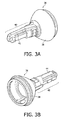
- the coupling assembly is shown in more detail in Figures 3A and 3B . It includes a base portion 36, the lower end of which may be configured to receive ring 28. Forward of ring 28 is an inwardly angled surface portion 38, substantially cone-shaped. Forwardly of the angled portion 38 is a coupling body portion 40.
- the body portion 40 includes an internal axial opening which receives the driveshaft 14. Along one side of the body portion 40 is a rib 41 which extends for substantially the length of the body portion, the rib fitting snugly into a mating slot in arm portion 24. The rib 41 locates and maintains the physical relationship between the coupling assembly and the arm portion 24.
- coupling strip 44 On the opposite side of the body portion from rib 41 is a coupling strip 44. This is shown in both Figures 3B and Figure 5 .
- coupling strip 44 is fixedly mounted to the body portion 40 at the opposing ends of the strip and is free to flex to some extent between its two ends.
- the body portion 40 is made from acetal which permits flexing of the coupling strip to occur, while being tough enough to resist abrasion and compression deformation or creep during the life of the brushhead.
- Coupling strip 44 is approximately 0.6 mm long and approximately 0.3 mm wide. It is approximately 0.80 mm thick, except for a first interface contact member portion 46, which is approximately 1.323 mm thick.
- the first interface contact member 46 is a bulge or block which extends inwardly from coupling strip 44 approximately 0.16 mm, sufficient to make a significant physical contact with the inserted driveshaft 14.
- the first interface contact member could be located on spring member 34, in which case the coupling strip 44 could be eliminated.
- spring member 34 is positioned around a part of the body portion 40 of the coupling assembly.
- Spring member 34 is shown in more detail in Figure 4 .
- the spring member is, in the embodiment shown, an angled C-shaped configuration, although it could be other configurations, including an oval or a closed arrangement.
- the spring could also be a leaf spring or a coil spring.
- Spring member 34 is arranged and configured to provide an inwardly directed force against the body portion of the coupling assembly with sufficient frictional and physical contact between the body portion and the driveshaft to produce the desired torque transfer as well as axial retention. In the embodiment shown, this force is in the range of 30-60 newtons, preferably approximately 50 newtons.
- the body portion of the coupling assembly and the extending portion of the driveshaft can be of various configurations to achieve this desired functional result.
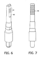
- a contact portion 49 on the driveshaft includes a plurality of grooves 50 which extend laterally across the contact portion, which is flat.
- the grooves are approximately 0.10 mm deep, have a generally curved configuration, with a distance of 0.65 mm center to center.
- the physical interaction between the grooves 50 in the first contact portion of the driveshaft and the first interface contact member 46 produces a good torque transfer between the driveshaft and the brushhead assembly, as well as sufficient axial retention to maintain the brushhead assembly on the driveshaft during operation of the toothbrush.
- the axial retention is also such as to permit the user to conveniently remove the brushhead from the driveshaft for cleaning and the like, without degrading the torque transfer and axial retention functions.
- Figure 7 shows another embodiment of a driveshaft contact portion 55.
- contact portion 55 has been roughened, such as by sandblasting or the like.
- the surface finish is 0.80 ⁇ meters or rougher, e.g. up to 1.6 ⁇ meters.
- This driveshaft surface, with the interface contact member 46 of the coupling member described above, is also sufficient to accomplish the desired torque transfer and axial retention functions.
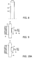
- Figure 9 shows a simplified representation of the embodiment of Figures 5 , 6 and 8 . It includes a grooved driveshaft 64, an interface contact member 66 of a coupling member and a representation of the spring function at 68. Portions 70-70 refer generally to the brushhead assembly arm, in which the coupling assembly is mounted. Portion 69 refers to the part of the coupling member on the opposite side of the driveshaft from the interface contact member. In this embodiment, the spring pressure is against the interface contact member, which bears directly against the grooves 71 on the driveshaft 64.
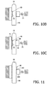
- Figures 10A-10C show another embodiment in which driveshaft 72 has a slot in a surface thereof, the slot being sufficiently large to accommodate an interface contact member portion of the coupling assembly.
- Each of the embodiments of Figures 10A-10C includes a spring function 73.
- Figure 10A shows a slot 74 in surface 76 of driveshaft 72 and an interface contact member 77 fitting therein.
- Figure 10B shows a slot 80 in surface 81 of the driveshaft opposite from spring function 73 and an interface contact member 75 which extends from coupling assembly on the opposite side from spring function73 into slot 80.
- Figure 10C shows a driveshaft 72 with slots 86 and 88 on both (opposing) sides of the driveshaft, into which are fitted a first interface contact member 90 on the same side of the driveshaft as spring function 73, and a second interface contact member 92 extending from coupling assembly 93 on the opposite side of the driveshaft from spring function 73.
- FIG 11 shows a further embodiment, in which a driveshaft 96 includes a protrusion 98 from surface 99 thereof, on the spring function side of the driveshaft.
- Interface contact member 100 is positioned adjacent to one end 102 of the driveshaft protrusion 98.
- FIGs 12A-12C show additional embodiments in which protrusions are located on one or both sides of the driveshaft, with the interface contact members having a slot into which the protrusions fit.
- driveshaft 104 includes a protrusion 106 on the spring function side of the driveshaft.
- Interface contact member 108 includes a slot 110 into which protrusion 106 fits.
- Figure 12B shows a driveshaft 112 with a protrusion 118 on the side opposite from the spring function side. Protrusion 118 fits into a slot 114 in the coupling assembly on the side opposite from the spring function side of the coupling assembly.
- Figure 12C shows a driveshaft 124 having protrusions 132 and 136 on opposing sides of the driveshaft.
- interface contact member 130 On the spring side of the driveshaft is interface contact member 130, which has a slot 126 therein to receive protrusion 132, while in the opposing side of the coupling assembly is a slot 128 into which fits protrusion 136.
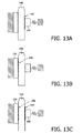
- Figures 13A-13C show further embodiments with roughened surfaces on contact portions of the driveshaft, like that shown in Figure 7 .
- Figure 13A includes a driveshaft 140 having a roughened surface region 142 on the spring function side of the driveshaft. Interface contact member 144 makes sufficient physical contact with the roughened surface 142 to accomplish the desired functions.
- Figure 13B shows a driveshaft 146 with a roughened surface region 148 on the side of the driveshaft opposite from the spring function. Coupling assembly portion 150 on the opposite side of the driveshaft makes the required physical contact with the roughened region 148.
- Figure 13C shows a driveshaft 152 with roughened surface regions 154 and 156 on opposite sides of the driveshaft.
- Interface contact member 160 engages roughened surface region 154, while the surface of coupling assembly portion 164 on the opposite side from interface member 160 engages roughened surface region 156.
Abstract
Description
- This invention relates generally to handle/brushhead interface arrangements for power toothbrushes, and more specifically concerns such an interface in which the torque transfer function and axial retention function of the brushhead relative to the toothbrush driveshaft is accomplished by a single spring and coupling combination.
- Many power toothbrushes have a structural arrangement in which a driveshaft, driven rotationally or through a selected angle of oscillation, extends from a handle portion of the toothbrush, with the drive mechanism being contained within the handle portion. A removable brushhead assembly fits onto the extending driveshaft. The brushhead assembly includes a coupling member, which fits into an arm portion of the brushhead assembly. At the distal end of the arm portion is a brush member for cleaning teeth. The driveshaft extends into and securely mates with the coupling member.
- The structural interaction between the drive shaft and the coupling member must be such as to reliably transfer the torque of the moving driveshaft to the brushhead and to maintain the torque transfer under load. The load refers to a combination of the torque created by the inertial mass of the oscillating brushhead and the forces created by the interaction with the tissues and other elements of the user's mouth. The structural interaction must also be sufficient to hold the brushhead on the driveshaft, which is referred to as axial retention, during operation of the toothbrush, while also permitting the brushhead to be conveniently removed by the user. Axial retention can be a challenging aspect of such an arrangement if the brushhead is to be removed regularly for cleaning or other purposes. The arrangement must be such that the functions of torque transfer and axial retention are not degraded even after the brushhead assembly has been removed numerous, perhaps hundreds, of times during the lifetime of the brushhead assembly.
- It is known from
WO0289929 - The present arrangement is capable of reliably providing both the torque transfer and the axial retention functions, while permitting a large number of removals of the brushhead assembly from the driveshaft.
- This object is achieved by a brushhead / handle interface for a power toothbrush, comprising:
- a brushhead assembly having a brush member at one end thereof for cleaning teeth;
- a driveshaft extending from a handle portion of the toothbrush, driven such that it oscillates through a selected rotational angle, the driveshaft having one or more contact regions in which are located interface surfaces;
- a coupling member positioned at the other end of the brushhead assembly and having a body portion with an internal axial opening for receiving the driveshaft, wherein the coupling member includes one or more interface portions which come into physical contact with said interface surfaces of the driveshaft when the driveshaft is inserted into the coupling member; and
- a spring member positioned around a part of the body portion so as to exert a force against the coupling member large enough that the physical contact between said interface portion or portions of the coupling member and said one or more contact regions of the driveshaft is sufficient to produce a reliable torque transfer between the driveshaft and the brushhead assembly and to maintain axial retention of the brushhead assembly on the driveshaft during operation of the toothbrush, while permitting a user to remove the brushhead assembly from the driveshaft when the toothbrush is not operating.
-
-
Figure 1 is a partially exploded view of a toothbrush described herein comprising a handle portion and a brushhead assembly portion. -
Figure 2 is an exploded view of the brushhead assembly portion ofFigure 1 . -
Figures 3A and 3B are isometric views of the coupling member shown inFigure 2 . -
Figure 4 is an isometric view of a spring member portion of the brushhead assembly ofFigure 2 . -
Figure 5 is a cross-sectional view of the coupling member ofFigure 2 . -
Figure 6 is an isometric view of a driveshaft with a first contact surface embodiment. -
Figure 7 is an elevational view of a driveshaft with another contact surface embodiment. -
Figure 8 is a side elevational view of the driveshaft ofFigure 6 . -
Figure 9 is a simplified cross-sectional view of the handle/brushhead assembly interface ofFigures 5 ,6 and8 . -
Figures 10A-10C are simplified cross-sectional views of three variations of another embodiment of the brushhead assembly/handle interface. -
Figure 11 is a simplified cross-sectional view of another embodiment of the brushhead assembly/handle interface. -
Figures 12A-12C are simplified cross-sectional views of three variations of another embodiment of the brushhead assembly/handle interface. -
Figures 13A-13C are simplified cross-sectional views of three variations of a still further embodiment of the brushhead assembly/handle interface. -
Figure 1 shows atoothbrush 10 which includes ahandle portion 12 with a drive assembly which includes an extendingdriveshaft 14, the driveshaft driven by a motor (not shown) positioned withinhandle 12. The motor moves the driveshaft in an oscillating manner through a selected angle. The motor is controlled by a user-operated on/offswitch 16. Removably mounted ondriveshaft 14 is abrushhead assembly 20. - Referring to
Figure 2 , thebrushhead assembly 20 includes acoupling assembly 22 which fits snugly into and is captured by anarm portion 24 of the brushhead assembly. Positioned on a distal end of the arm portion is aconventional brush member 26 which cleans the teeth. In operation,brush member 26 rotates/oscillates back and forth through a selected angle to accomplish the desired cleansing. The coupling assembly may further include aring 28 at theproximal end 30 of the coupling assembly. The ring can be different colors to identify the user of the brushhead assembly. The coupling assembly further includes aspring member 34 which fits around a portion of the body of thecoupling assembly 22. - The coupling assembly is shown in more detail in
Figures 3A and 3B . It includes abase portion 36, the lower end of which may be configured to receivering 28. Forward ofring 28 is an inwardlyangled surface portion 38, substantially cone-shaped. Forwardly of theangled portion 38 is acoupling body portion 40. Thebody portion 40 includes an internal axial opening which receives thedriveshaft 14. Along one side of thebody portion 40 is arib 41 which extends for substantially the length of the body portion, the rib fitting snugly into a mating slot inarm portion 24. Therib 41 locates and maintains the physical relationship between the coupling assembly and thearm portion 24. - On the opposite side of the body portion from
rib 41 is acoupling strip 44. This is shown in bothFigures 3B andFigure 5 . In the embodiment shown,coupling strip 44 is fixedly mounted to thebody portion 40 at the opposing ends of the strip and is free to flex to some extent between its two ends. Thebody portion 40 is made from acetal which permits flexing of the coupling strip to occur, while being tough enough to resist abrasion and compression deformation or creep during the life of the brushhead.Coupling strip 44 is approximately 0.6 mm long and approximately 0.3 mm wide. It is approximately 0.80 mm thick, except for a first interfacecontact member portion 46, which is approximately 1.323 mm thick. The firstinterface contact member 46 is a bulge or block which extends inwardly fromcoupling strip 44 approximately 0.16 mm, sufficient to make a significant physical contact with the inserteddriveshaft 14. Alternatively, the first interface contact member could be located onspring member 34, in which case thecoupling strip 44 could be eliminated. - As indicated above,
spring member 34 is positioned around a part of thebody portion 40 of the coupling assembly.Spring member 34 is shown in more detail inFigure 4 . The spring member is, in the embodiment shown, an angled C-shaped configuration, although it could be other configurations, including an oval or a closed arrangement. The spring could also be a leaf spring or a coil spring.Spring member 34 is arranged and configured to provide an inwardly directed force against the body portion of the coupling assembly with sufficient frictional and physical contact between the body portion and the driveshaft to produce the desired torque transfer as well as axial retention. In the embodiment shown, this force is in the range of 30-60 newtons, preferably approximately 50 newtons. The body portion of the coupling assembly and the extending portion of the driveshaft can be of various configurations to achieve this desired functional result. - In one embodiment, referring to
Figures 6 and8 , acontact portion 49 on the driveshaft includes a plurality ofgrooves 50 which extend laterally across the contact portion, which is flat. In this embodiment, there are a total of five grooves, which number can be varied. The grooves are approximately 0.10 mm deep, have a generally curved configuration, with a distance of 0.65 mm center to center. The physical interaction between thegrooves 50 in the first contact portion of the driveshaft and the firstinterface contact member 46 produces a good torque transfer between the driveshaft and the brushhead assembly, as well as sufficient axial retention to maintain the brushhead assembly on the driveshaft during operation of the toothbrush. The axial retention is also such as to permit the user to conveniently remove the brushhead from the driveshaft for cleaning and the like, without degrading the torque transfer and axial retention functions. -
Figure 7 shows another embodiment of adriveshaft contact portion 55. In this embodiment,contact portion 55 has been roughened, such as by sandblasting or the like. The surface finish is 0.80 µmeters or rougher, e.g. up to 1.6 µmeters. This driveshaft surface, with theinterface contact member 46 of the coupling member described above, is also sufficient to accomplish the desired torque transfer and axial retention functions. -
Figure 9 shows a simplified representation of the embodiment ofFigures 5 ,6 and8 . It includes agrooved driveshaft 64, aninterface contact member 66 of a coupling member and a representation of the spring function at 68. Portions 70-70 refer generally to the brushhead assembly arm, in which the coupling assembly is mounted.Portion 69 refers to the part of the coupling member on the opposite side of the driveshaft from the interface contact member. In this embodiment, the spring pressure is against the interface contact member, which bears directly against thegrooves 71 on thedriveshaft 64. -
Figures 10A-10C show another embodiment in whichdriveshaft 72 has a slot in a surface thereof, the slot being sufficiently large to accommodate an interface contact member portion of the coupling assembly. Each of the embodiments ofFigures 10A-10C includes aspring function 73.Figure 10A shows aslot 74 insurface 76 ofdriveshaft 72 and aninterface contact member 77 fitting therein.Figure 10B shows aslot 80 insurface 81 of the driveshaft opposite fromspring function 73 and aninterface contact member 75 which extends from coupling assembly on the opposite side from spring function73 intoslot 80.Figure 10C shows adriveshaft 72 withslots interface contact member 90 on the same side of the driveshaft asspring function 73, and a secondinterface contact member 92 extending from couplingassembly 93 on the opposite side of the driveshaft fromspring function 73. -
Figure 11 shows a further embodiment, in which adriveshaft 96 includes aprotrusion 98 fromsurface 99 thereof, on the spring function side of the driveshaft.Interface contact member 100 is positioned adjacent to oneend 102 of thedriveshaft protrusion 98. -
Figures 12A-12C show additional embodiments in which protrusions are located on one or both sides of the driveshaft, with the interface contact members having a slot into which the protrusions fit. InFigure 12A ,driveshaft 104 includes aprotrusion 106 on the spring function side of the driveshaft.Interface contact member 108 includes aslot 110 into whichprotrusion 106 fits.Figure 12B shows adriveshaft 112 with aprotrusion 118 on the side opposite from the spring function side.Protrusion 118 fits into aslot 114 in the coupling assembly on the side opposite from the spring function side of the coupling assembly.Figure 12C shows adriveshaft 124 havingprotrusions interface contact member 130, which has aslot 126 therein to receiveprotrusion 132, while in the opposing side of the coupling assembly is aslot 128 into which fitsprotrusion 136. -
Figures 13A-13C show further embodiments with roughened surfaces on contact portions of the driveshaft, like that shown inFigure 7 .Figure 13A includes adriveshaft 140 having a roughenedsurface region 142 on the spring function side of the driveshaft.Interface contact member 144 makes sufficient physical contact with the roughenedsurface 142 to accomplish the desired functions.Figure 13B shows adriveshaft 146 with a roughenedsurface region 148 on the side of the driveshaft opposite from the spring function. Couplingassembly portion 150 on the opposite side of the driveshaft makes the required physical contact with the roughenedregion 148.Figure 13C shows adriveshaft 152 with roughenedsurface regions Interface contact member 160 engages roughenedsurface region 154, while the surface ofcoupling assembly portion 164 on the opposite side frominterface member 160 engages roughenedsurface region 156. - It should be understood that other arrangements/configurations between the driveshaft and portions of the coupling assembly are possible.
- Although a preferred embodiment of the invention has been disclosed here for the purposes of illustration, it should be understood that various changes, modifications and substitutions may be incorporated in the embodiment without departing from the invention, which is defined by the claims which follow.
Claims (13)
- A brushhead / handle interface for a power toothbrush (10), comprising:a brushhead assembly (20) having a brush member (26) at one end thereof for cleaning teeth;a driveshaft (14) extending from a handle portion (12) of the toothbrush (10), driven such that it oscillates through a selected rotational angle, the driveshaft (14) having one or more contact regions (49) in which are located interface surfaces (50);a coupling member (22) positioned at the other end of the brushhead assembly (20) and having a body portion (40) with an internal axial opening for receiving the driveshaft (14), wherein the coupling member (22) includes one or more interface portions (46) which come into physical contact with said interface surfaces (50) of the driveshaft (14) when the driveshaft (14) is inserted into the coupling member (22); anda spring member (34) positioned around a part of the body portion (40) so as to exert a force against the coupling member (22) large enough that the physical contact between said interface portion or portions (46) of the coupling member (22) and said one or more contact regions (50) of the driveshaft (14) is sufficient to produce a reliable torque transfer between the driveshaft (14) and the brushhead assembly (20) and to maintain axial retention of the brushhead assembly (20) on the driveshaft (14) during operation of the toothbrush (10), while permitting a user to remove the brushhead assembly (20) from the driveshaft (14) when the toothbrush (10) is not operating.
- The interface of claim 1, wherein the coupling member (22) includes a coupling strip member (44) fixedly mounted to the body portion (40) of the coupling member (22) at the opposing ends of the strip member (44) and is free to flex to some extent between its two ends so as to permit movement of the strip member (44) therebetween, and wherein the coupling strip member (44) includes an interface portion (46), extending inwardly in the direction of the driveshaft (14), resulting in physical contact between said interface portion (46) and an interface surface (56) of the driveshaft (14) when the driveshaft (14) is received in the brushhead assembly (20).
- The interface of claim 1, wherein the user is able to remove the brushhead assembly (20) a large plurality of times without degrading the torque transfer and axial retention capabilities.
- The interface of claim 1, wherein the spring member (34) is substantially C-shaped in cross-section.
- The interface of claim 2, wherein the interface surfaces (50) of the driveshaft (14) include a plurality of lateral grooves (50) which extend across the contact region of the driveshaft (14) and wherein the interface portion (46) of the coupling member (22) is substantially larger than any of the grooves (50).
- The interface of claim 2, wherein the interface surfaces of the driveshaft (72) include a slot (74), and wherein an interface portion (77) of the coupling member is configured to fit within the slot (74).
- The interface of claim 6, wherein the interface surfaces of the driveshaft (72) include a slot (80) on a side of the driveshaft opposite from a side against which the spring force is exerted, and wherein one of the interface portions (75) of the coupling member includes a protrusion configured to fit within said slot (80).
- The interface of claim 6, wherein the interface surfaces of the driveshaft (72) include slots (86, 88) in opposing sides thereof and wherein, the interface portions (90, 92) of the coupling member include protrusions configured to fit within the slots (86, 88).
- The interface of claim 1, wherein the interface surfaces of the driveshaft (96) include a protrusion (98) and wherein an interface portion (100) of the coupling member fits against the driveshaft (96) adjacent the protrusion (98).
- The interface of claim 1, wherein the interface surfaces of the driveshaft (104) include at least one protrusion (106) extending therefrom, and wherein the interface portions of the coupling member include a slot (110) into which the driveshaft protrusion fits.
- The interface of claim 10, wherein the interface surfaces of the driveshaft (124) include protrusions (132, 136) on opposing sides thereof, and wherein the interface portions of the coupling member include slots (126, 128) which receive the protrusions (132, 136).
- The interface of claim 1, wherein the interface surfaces of the driveshaft (140) include at least one roughened region (142), and wherein an interface portion (144) of the coupling member makes said physical contact with the roughened portion (142).
- The interface of claim 12, wherein the interface surfaces of the driveshaft (152) include roughened regions (154, 156) on opposing sides of the driveshaft (152) and wherein the interface portions (160, 164) of the coupling member make said physical contact with the roughened regions (154, 156).
Applications Claiming Priority (2)
| Application Number | Priority Date | Filing Date | Title |
|---|---|---|---|
| US1449607P | 2007-12-18 | 2007-12-18 | |
| PCT/IB2008/055168 WO2009077922A1 (en) | 2007-12-18 | 2008-12-09 | A brushhead/handle interface for a power toothbrush |
Publications (2)
| Publication Number | Publication Date |
|---|---|
| EP2234561A1 EP2234561A1 (en) | 2010-10-06 |
| EP2234561B1 true EP2234561B1 (en) | 2012-08-08 |
Family
ID=40601374
Family Applications (1)
| Application Number | Title | Priority Date | Filing Date |
|---|---|---|---|
| EP08862717A Active EP2234561B1 (en) | 2007-12-18 | 2008-12-09 | A brushhead/handle interface for a power toothbrush |
Country Status (10)
| Country | Link |
|---|---|
| US (1) | US8782841B2 (en) |
| EP (1) | EP2234561B1 (en) |
| JP (1) | JP5734663B2 (en) |
| KR (1) | KR101537530B1 (en) |
| CN (1) | CN101902986B (en) |
| BR (1) | BRPI0820849A2 (en) |
| CA (1) | CA2709756C (en) |
| ES (1) | ES2391921T3 (en) |
| RU (1) | RU2489117C2 (en) |
| WO (1) | WO2009077922A1 (en) |
Cited By (4)
| Publication number | Priority date | Publication date | Assignee | Title |
|---|---|---|---|---|
| EP3470015A1 (en) | 2017-10-11 | 2019-04-17 | Trisa Holding AG | Brush head, electrical toothbrush handle and electric toothbrush with the electric toothbrush handle and the brush head |
| CN109661214A (en) * | 2016-08-19 | 2019-04-19 | 皇家飞利浦有限公司 | Method for the installation and removal of detection accessory head |
| EP3865088A1 (en) | 2020-02-17 | 2021-08-18 | Trisa Holding AG | Push-on brush device |
| EP4069137B1 (en) * | 2019-12-03 | 2024-04-03 | Koninklijke Philips N.V. | A brush head for an oral care device and method of assembling the same |
Families Citing this family (48)
| Publication number | Priority date | Publication date | Assignee | Title |
|---|---|---|---|---|
| PL2335643T3 (en) * | 2009-12-16 | 2016-06-30 | Braun Gmbh | Oral cleaning section of an oral cleaning device and oral cleaning device |
| WO2012020351A2 (en) * | 2010-08-09 | 2012-02-16 | Koninklijke Philips Electronics N.V. | A flexible drive shaft for an eccentric weight-driven personal care appliance |
| WO2012085718A1 (en) * | 2010-12-20 | 2012-06-28 | Koninklijke Philips Electronics N.V. | A power toothbrush and brushhead therefor, with multiple motion brush member |
| BR112014009443A2 (en) | 2011-10-25 | 2017-04-25 | Koninklijke Philips Nv | brush head replacement assembly for an electric toothbrush having a cable part and an output shaft for the brush head drive |
| DE102012006723B4 (en) | 2012-04-02 | 2020-06-18 | M + C Schiffer Gmbh | Brush head attachment |
| US9237943B2 (en) | 2013-09-24 | 2016-01-19 | M+C Schiffer Gmbh | Brush head attachment |
| EP3060162B1 (en) * | 2013-10-25 | 2018-08-29 | Koninklijke Philips N.V. | Attachment for an electric toothbrush handle and method of attaching |
| USD766581S1 (en) | 2013-12-19 | 2016-09-20 | Colgate-Palmolive Company | Electric toothbrush handle |
| USD776435S1 (en) | 2013-12-19 | 2017-01-17 | Colgate-Palmolive Company | Head portion of a toothbrush |
| USD769626S1 (en) | 2013-12-19 | 2016-10-25 | Colgate-Palmolive Company | Refill head for electric toothbrush |
| WO2016181323A1 (en) * | 2015-05-14 | 2016-11-17 | Koninklijke Philips N.V. | An attachment structure for a personal care appliance, a personal care appliance and a method |
| USD794333S1 (en) | 2015-11-25 | 2017-08-15 | Colgate-Palmolive Company | Electric toothbrush brush head |
| USD790860S1 (en) | 2015-11-25 | 2017-07-04 | Colgate-Palmolive Company | Electric toothbrush brush head |
| WO2017088113A1 (en) | 2015-11-25 | 2017-06-01 | 上海携福电器有限公司 | Head module capable of reciprocal rotation for electric cleaning apparatus |
| US10617595B2 (en) * | 2016-08-31 | 2020-04-14 | Steffan MARTELL | Tissue massager |
| US11173021B2 (en) * | 2016-11-03 | 2021-11-16 | Mihran Papazian | Replacement head assembly for toothbrushing systems |
| US9724180B1 (en) | 2017-01-06 | 2017-08-08 | Harria Investment Group Inc. | Brush head for electric toothbrush |
| USD830699S1 (en) | 2017-02-03 | 2018-10-16 | Harria Investment Group Ltd. | Brush head for an electric toothbrush |
| USD838990S1 (en) | 2017-05-11 | 2019-01-29 | Harria Investment Group Ltd | Brush head for an electric toothbrush |
| CN109223230B (en) * | 2017-07-11 | 2020-09-25 | Js控股股份有限公司 | Removable brush head for a power toothbrush |
| USD858105S1 (en) | 2017-11-17 | 2019-09-03 | Colgate-Palmolive Company | Oral care implement |
| USD858997S1 (en) | 2017-11-17 | 2019-09-10 | Colgate-Palmolive Company | Tracking module for an oral care implement |
| USD893881S1 (en) | 2017-11-17 | 2020-08-25 | Colgate-Palmolive Company | Oral care apparatus |
| USD869855S1 (en) | 2018-07-24 | 2019-12-17 | Burst.USA Inc. | Toothbrush handle |
| CN109008178A (en) * | 2018-10-19 | 2018-12-18 | 吴晓旺 | A kind of disposable toothbrush head |
| CN110151348B (en) * | 2019-03-14 | 2024-04-19 | 胡斐凡 | Brush head assembly and electric toothbrush |
| CN109846570A (en) * | 2019-04-15 | 2019-06-07 | 广州皓醒湾科技有限公司 | A kind of electric toothbrush |
| CN114007543A (en) * | 2019-05-20 | 2022-02-01 | 博朗有限公司 | Bristle driven pulsation |
| WO2021071653A1 (en) * | 2019-10-08 | 2021-04-15 | Ranir, Llc | Attachment portion for an electric toothbrush replacement head |
| US11311096B2 (en) * | 2020-03-18 | 2022-04-26 | Water Pik, Inc. | Brush head for an oral cleansing device |
| WO2021217535A1 (en) | 2020-04-30 | 2021-11-04 | Colgate-Palmolive Company | Oral care implement and refill head thereof |
| USD954441S1 (en) | 2020-07-20 | 2022-06-14 | Js Holding Inc. | Brush head for electric toothbrush |
| US11071613B1 (en) | 2020-07-20 | 2021-07-27 | Js Holding Inc. | Structure for coupling toothbrush head to electric toothbrush handle |
| US20220022634A1 (en) * | 2020-07-24 | 2022-01-27 | Paris Presents Incorporated | Interchangeable Makeup Brush |
| US11439488B2 (en) | 2020-08-07 | 2022-09-13 | Juan-Yun Kuang | Brushhead for power toothbrush |
| WO2022028613A1 (en) * | 2020-08-07 | 2022-02-10 | 匡娟云 | Electric toothbrush head and electric toothbrush |
| US10912377B1 (en) * | 2020-08-07 | 2021-02-09 | Juan-Yun Kuang | Electric toothbrush brush head and electric toothbrush |
| US11413126B2 (en) | 2020-08-07 | 2022-08-16 | Juan-Yun Kuang | Brushhead for power toothbrush |
| US11666137B2 (en) | 2020-08-07 | 2023-06-06 | Juan-Yun Kuang | Brushhead for power toothbrush |
| US20240050215A1 (en) | 2020-12-16 | 2024-02-15 | Koninklijke Philips N.V. | Toothbrush with tapping motion |
| USD971611S1 (en) | 2020-12-17 | 2022-12-06 | Chunyang Liu | Toothbrush head |
| CN113081355A (en) | 2021-04-16 | 2021-07-09 | 林高生 | Electric toothbrush head and electric toothbrush |
| USD961268S1 (en) | 2021-09-27 | 2022-08-23 | Chaorui Kuang | Toothbrush head |
| USD968813S1 (en) | 2021-09-27 | 2022-11-08 | Chaorui Kuang | Toothbrush head |
| US20230140465A1 (en) * | 2021-11-04 | 2023-05-04 | Water Pik, Inc. | Removable brush head |
| USD970895S1 (en) | 2022-04-07 | 2022-11-29 | Shengzhou Li | Toothbrush head |
| DE202022002462U1 (en) | 2022-11-16 | 2023-01-24 | Truemorrow Gmbh | Interchangeable attachment for electric toothbrushes |
| CN220404177U (en) | 2023-05-10 | 2024-01-30 | 宁波赛嘉电器有限公司 | Brush head |
Citations (1)
| Publication number | Priority date | Publication date | Assignee | Title |
|---|---|---|---|---|
| WO2002089929A1 (en) * | 2001-05-07 | 2002-11-14 | The Procter & Gamble Company | Electric toothbrush with replaceable head and connection structure therefor |
Family Cites Families (22)
| Publication number | Priority date | Publication date | Assignee | Title |
|---|---|---|---|---|
| US3369265A (en) * | 1966-07-07 | 1968-02-20 | Vistron Corp | Universal toothbrush head |
| CH535042A (en) * | 1971-02-26 | 1973-03-31 | Woog Inst Rech | Plug-in device on a hand-held device, which is used in particular for personal hygiene, for attaching exchangeable treatment instruments |
| JPH0440905A (en) | 1990-06-07 | 1992-02-12 | Hiroshi Fukuba | Motor-driven rolling toothbrush |
| BE1007374A3 (en) * | 1993-07-30 | 1995-05-30 | Philips Electronics Nv | Toothbrush. |
| US5697117A (en) * | 1996-01-26 | 1997-12-16 | Teledyne Industries, Inc. | Brush head assembly for motor powered toothbrush |
| DE19627752A1 (en) * | 1996-07-10 | 1998-01-15 | Braun Ag | Electric toothbrush |
| DE19745876A1 (en) * | 1997-10-17 | 1999-04-22 | Braun Ag | Brush part for electric toothbrush |
| US5842245A (en) * | 1998-05-26 | 1998-12-01 | Pai; Chung-Jen | Electric toothbrush assembly |
| AU6149500A (en) | 1999-06-10 | 2001-01-02 | Gimelli Produktions Ag | Slip-on brush designed for a hand part of an electric toothbrush |
| GB0010115D0 (en) * | 2000-04-27 | 2000-06-14 | Smithkline Beecham Gmbh & Co | Toothbrush |
| JP4436554B2 (en) * | 2000-09-29 | 2010-03-24 | ピーアイエー株式会社 | Paint roller |
| PT1367958E (en) * | 2001-03-14 | 2008-01-24 | Braun Gmbh | Device for cleaning teeth |
| US6536066B2 (en) * | 2001-07-25 | 2003-03-25 | Pulse Innovations Inc. | Toothbrush oscillating head |
| JP4040905B2 (en) * | 2002-05-16 | 2008-01-30 | 株式会社リコー | Reduced image display device, method, program, and recording medium recording program |
| TW527913U (en) * | 2002-07-22 | 2003-04-11 | Jeng-Jie Jiang | Structure of brush head for electromotive toothbrush |
| US20040134001A1 (en) * | 2002-09-13 | 2004-07-15 | The Procter & Gamble Company | Toothbrushes with a replaceable head having a threaded connection |
| JP3096312U (en) * | 2003-03-06 | 2003-09-12 | 正傑 江 | Electric toothbrush brush head |
| CN1812750B (en) * | 2003-06-27 | 2012-04-18 | 皇家飞利浦电子股份有限公司 | Brushhead attachment system for a power toothbrush |
| DE10352993A1 (en) * | 2003-11-13 | 2005-06-16 | Braun Gmbh | Brush part for an electric toothbrush |
| GB0329678D0 (en) * | 2003-12-22 | 2004-01-28 | Glaxosmithkline Consumer Healt | Toothbrush |
| JP2006068361A (en) * | 2004-09-03 | 2006-03-16 | Pigeon Corp | Toothbrush |
| JP2006066305A (en) * | 2004-08-30 | 2006-03-09 | Yokowo Co Ltd | Spring connector |
-
2008
- 2008-12-09 US US12/374,871 patent/US8782841B2/en active Active
- 2008-12-09 ES ES08862717T patent/ES2391921T3/en active Active
- 2008-12-09 RU RU2010129936/14A patent/RU2489117C2/en active
- 2008-12-09 EP EP08862717A patent/EP2234561B1/en active Active
- 2008-12-09 JP JP2010538969A patent/JP5734663B2/en active Active
- 2008-12-09 WO PCT/IB2008/055168 patent/WO2009077922A1/en active Application Filing
- 2008-12-09 BR BRPI0820849-2A patent/BRPI0820849A2/en not_active Application Discontinuation
- 2008-12-09 CN CN200880121230.6A patent/CN101902986B/en active Active
- 2008-12-09 CA CA2709756A patent/CA2709756C/en not_active Expired - Fee Related
- 2008-12-09 KR KR1020107015891A patent/KR101537530B1/en active IP Right Grant
Patent Citations (1)
| Publication number | Priority date | Publication date | Assignee | Title |
|---|---|---|---|---|
| WO2002089929A1 (en) * | 2001-05-07 | 2002-11-14 | The Procter & Gamble Company | Electric toothbrush with replaceable head and connection structure therefor |
Cited By (9)
| Publication number | Priority date | Publication date | Assignee | Title |
|---|---|---|---|---|
| CN109661214A (en) * | 2016-08-19 | 2019-04-19 | 皇家飞利浦有限公司 | Method for the installation and removal of detection accessory head |
| CN109661214B (en) * | 2016-08-19 | 2021-10-29 | 皇家飞利浦有限公司 | Method for detecting attachment head installation and removal |
| EP3470015A1 (en) | 2017-10-11 | 2019-04-17 | Trisa Holding AG | Brush head, electrical toothbrush handle and electric toothbrush with the electric toothbrush handle and the brush head |
| WO2019072994A1 (en) | 2017-10-11 | 2019-04-18 | Trisa Holding Ag | Brush attachment, electric toothbrush handpiece and electric toothbrush comprising the electric toothbrush handpiece and the brush attachment |
| US11666426B2 (en) | 2017-10-11 | 2023-06-06 | Trisa Holding Ag | Brush attachment, electric toothbrush handpiece and electric toothbrush comprising the electric toothbrush handpiece and the brush attachment |
| EP4201376A1 (en) | 2017-10-11 | 2023-06-28 | Trisa Holding AG | Electric toothbrush handpiece and electric toothbrush comprising the electric toothbrush handpiece and a brush attachment |
| EP4069137B1 (en) * | 2019-12-03 | 2024-04-03 | Koninklijke Philips N.V. | A brush head for an oral care device and method of assembling the same |
| EP3865088A1 (en) | 2020-02-17 | 2021-08-18 | Trisa Holding AG | Push-on brush device |
| WO2021165196A2 (en) | 2020-02-17 | 2021-08-26 | Trisa Holding Ag | Attachment brush device |
Also Published As
| Publication number | Publication date |
|---|---|
| CN101902986B (en) | 2013-11-06 |
| JP5734663B2 (en) | 2015-06-17 |
| KR101537530B1 (en) | 2015-07-21 |
| US20100251493A1 (en) | 2010-10-07 |
| WO2009077922A1 (en) | 2009-06-25 |
| JP2011506028A (en) | 2011-03-03 |
| KR20100106492A (en) | 2010-10-01 |
| RU2489117C2 (en) | 2013-08-10 |
| CA2709756C (en) | 2015-09-22 |
| EP2234561A1 (en) | 2010-10-06 |
| BRPI0820849A2 (en) | 2015-06-16 |
| CA2709756A1 (en) | 2009-06-25 |
| ES2391921T3 (en) | 2012-12-03 |
| CN101902986A (en) | 2010-12-01 |
| US8782841B2 (en) | 2014-07-22 |
| RU2010129936A (en) | 2012-01-27 |
Similar Documents
| Publication | Publication Date | Title |
|---|---|---|
| EP2234561B1 (en) | A brushhead/handle interface for a power toothbrush | |
| US7334283B2 (en) | Power toothbrush | |
| EP4041124B1 (en) | Replacement toothbrush head and system for attachment of a replacement toothbrush head onto an electric toothbrush | |
| CA2498230C (en) | Powered toothbrush | |
| JP5307831B2 (en) | Dental prophylaxis angle and handpiece assembly | |
| EP0651978A1 (en) | Improvements in brushes for personal hygiene purposes | |
| US9597169B2 (en) | Brushhead for a power toothbrush with a two position coupling assembly | |
| CN111372537A (en) | Refill head for an electric toothbrush | |
| US20130255014A1 (en) | Brushhead for a power toothbrush with a wedge and spring handle interface | |
| CN110913794A (en) | Electric tooth brush | |
| US20090019650A1 (en) | Powered toothbrush with flexible head | |
| WO2001012099A9 (en) | Drive mechanism for interproximal flossing device | |
| US20040049867A1 (en) | Electric toothbrush with in-use activation of bristles | |
| US20090019649A1 (en) | Electric toothbrush | |
| EP2468214B1 (en) | Cleaning section of an electric oral hygiene device | |
| CN211485034U (en) | Nursing head for oral nursing appliance and oral nursing appliance | |
| WO2012085844A2 (en) | Cleaning section of an electric oral hygiene device |
Legal Events
| Date | Code | Title | Description |
|---|---|---|---|
| PUAI | Public reference made under article 153(3) epc to a published international application that has entered the european phase |
Free format text: ORIGINAL CODE: 0009012 |
|
| 17P | Request for examination filed |
Effective date: 20100719 |
|
| AK | Designated contracting states |
Kind code of ref document: A1 Designated state(s): AT BE BG CH CY CZ DE DK EE ES FI FR GB GR HR HU IE IS IT LI LT LU LV MC MT NL NO PL PT RO SE SI SK TR |
|
| AX | Request for extension of the european patent |
Extension state: AL BA MK RS |
|
| 17Q | First examination report despatched |
Effective date: 20110209 |
|
| DAX | Request for extension of the european patent (deleted) | ||
| REG | Reference to a national code |
Ref country code: DE Ref legal event code: R079 Ref document number: 602008017913 Country of ref document: DE Free format text: PREVIOUS MAIN CLASS: A61C0017220000 Ipc: A61C0017340000 |
|
| RIC1 | Information provided on ipc code assigned before grant |
Ipc: A61C 17/34 20060101AFI20111219BHEP Ipc: A61C 17/22 20060101ALI20111219BHEP |
|
| GRAP | Despatch of communication of intention to grant a patent |
Free format text: ORIGINAL CODE: EPIDOSNIGR1 |
|
| GRAS | Grant fee paid |
Free format text: ORIGINAL CODE: EPIDOSNIGR3 |
|
| GRAA | (expected) grant |
Free format text: ORIGINAL CODE: 0009210 |
|
| AK | Designated contracting states |
Kind code of ref document: B1 Designated state(s): AT BE BG CH CY CZ DE DK EE ES FI FR GB GR HR HU IE IS IT LI LT LU LV MC MT NL NO PL PT RO SE SI SK TR |
|
| REG | Reference to a national code |
Ref country code: GB Ref legal event code: FG4D |
|
| REG | Reference to a national code |
Ref country code: CH Ref legal event code: EP Ref country code: AT Ref legal event code: REF Ref document number: 569316 Country of ref document: AT Kind code of ref document: T Effective date: 20120815 |
|
| REG | Reference to a national code |
Ref country code: IE Ref legal event code: FG4D |
|
| REG | Reference to a national code |
Ref country code: DE Ref legal event code: R096 Ref document number: 602008017913 Country of ref document: DE Effective date: 20121004 |
|
| REG | Reference to a national code |
Ref country code: ES Ref legal event code: FG2A Ref document number: 2391921 Country of ref document: ES Kind code of ref document: T3 Effective date: 20121203 |
|
| REG | Reference to a national code |
Ref country code: NL Ref legal event code: VDEP Effective date: 20120808 |
|
| REG | Reference to a national code |
Ref country code: AT Ref legal event code: MK05 Ref document number: 569316 Country of ref document: AT Kind code of ref document: T Effective date: 20120808 |
|
| REG | Reference to a national code |
Ref country code: LT Ref legal event code: MG4D Effective date: 20120808 |
|
| PG25 | Lapsed in a contracting state [announced via postgrant information from national office to epo] |
Ref country code: LT Free format text: LAPSE BECAUSE OF FAILURE TO SUBMIT A TRANSLATION OF THE DESCRIPTION OR TO PAY THE FEE WITHIN THE PRESCRIBED TIME-LIMIT Effective date: 20120808 Ref country code: AT Free format text: LAPSE BECAUSE OF FAILURE TO SUBMIT A TRANSLATION OF THE DESCRIPTION OR TO PAY THE FEE WITHIN THE PRESCRIBED TIME-LIMIT Effective date: 20120808 Ref country code: CY Free format text: LAPSE BECAUSE OF FAILURE TO SUBMIT A TRANSLATION OF THE DESCRIPTION OR TO PAY THE FEE WITHIN THE PRESCRIBED TIME-LIMIT Effective date: 20120808 Ref country code: FI Free format text: LAPSE BECAUSE OF FAILURE TO SUBMIT A TRANSLATION OF THE DESCRIPTION OR TO PAY THE FEE WITHIN THE PRESCRIBED TIME-LIMIT Effective date: 20120808 Ref country code: IS Free format text: LAPSE BECAUSE OF FAILURE TO SUBMIT A TRANSLATION OF THE DESCRIPTION OR TO PAY THE FEE WITHIN THE PRESCRIBED TIME-LIMIT Effective date: 20121208 Ref country code: HR Free format text: LAPSE BECAUSE OF FAILURE TO SUBMIT A TRANSLATION OF THE DESCRIPTION OR TO PAY THE FEE WITHIN THE PRESCRIBED TIME-LIMIT Effective date: 20120808 Ref country code: NO Free format text: LAPSE BECAUSE OF FAILURE TO SUBMIT A TRANSLATION OF THE DESCRIPTION OR TO PAY THE FEE WITHIN THE PRESCRIBED TIME-LIMIT Effective date: 20121108 |
|
| PG25 | Lapsed in a contracting state [announced via postgrant information from national office to epo] |
Ref country code: BE Free format text: LAPSE BECAUSE OF FAILURE TO SUBMIT A TRANSLATION OF THE DESCRIPTION OR TO PAY THE FEE WITHIN THE PRESCRIBED TIME-LIMIT Effective date: 20120808 Ref country code: GR Free format text: LAPSE BECAUSE OF FAILURE TO SUBMIT A TRANSLATION OF THE DESCRIPTION OR TO PAY THE FEE WITHIN THE PRESCRIBED TIME-LIMIT Effective date: 20121109 Ref country code: PT Free format text: LAPSE BECAUSE OF FAILURE TO SUBMIT A TRANSLATION OF THE DESCRIPTION OR TO PAY THE FEE WITHIN THE PRESCRIBED TIME-LIMIT Effective date: 20121210 Ref country code: LV Free format text: LAPSE BECAUSE OF FAILURE TO SUBMIT A TRANSLATION OF THE DESCRIPTION OR TO PAY THE FEE WITHIN THE PRESCRIBED TIME-LIMIT Effective date: 20120808 Ref country code: SI Free format text: LAPSE BECAUSE OF FAILURE TO SUBMIT A TRANSLATION OF THE DESCRIPTION OR TO PAY THE FEE WITHIN THE PRESCRIBED TIME-LIMIT Effective date: 20120808 Ref country code: SE Free format text: LAPSE BECAUSE OF FAILURE TO SUBMIT A TRANSLATION OF THE DESCRIPTION OR TO PAY THE FEE WITHIN THE PRESCRIBED TIME-LIMIT Effective date: 20120808 Ref country code: PL Free format text: LAPSE BECAUSE OF FAILURE TO SUBMIT A TRANSLATION OF THE DESCRIPTION OR TO PAY THE FEE WITHIN THE PRESCRIBED TIME-LIMIT Effective date: 20120808 |
|
| PG25 | Lapsed in a contracting state [announced via postgrant information from national office to epo] |
Ref country code: NL Free format text: LAPSE BECAUSE OF FAILURE TO SUBMIT A TRANSLATION OF THE DESCRIPTION OR TO PAY THE FEE WITHIN THE PRESCRIBED TIME-LIMIT Effective date: 20120808 |
|
| PG25 | Lapsed in a contracting state [announced via postgrant information from national office to epo] |
Ref country code: RO Free format text: LAPSE BECAUSE OF FAILURE TO SUBMIT A TRANSLATION OF THE DESCRIPTION OR TO PAY THE FEE WITHIN THE PRESCRIBED TIME-LIMIT Effective date: 20120808 Ref country code: DK Free format text: LAPSE BECAUSE OF FAILURE TO SUBMIT A TRANSLATION OF THE DESCRIPTION OR TO PAY THE FEE WITHIN THE PRESCRIBED TIME-LIMIT Effective date: 20120808 Ref country code: CZ Free format text: LAPSE BECAUSE OF FAILURE TO SUBMIT A TRANSLATION OF THE DESCRIPTION OR TO PAY THE FEE WITHIN THE PRESCRIBED TIME-LIMIT Effective date: 20120808 Ref country code: EE Free format text: LAPSE BECAUSE OF FAILURE TO SUBMIT A TRANSLATION OF THE DESCRIPTION OR TO PAY THE FEE WITHIN THE PRESCRIBED TIME-LIMIT Effective date: 20120808 |
|
| PG25 | Lapsed in a contracting state [announced via postgrant information from national office to epo] |
Ref country code: SK Free format text: LAPSE BECAUSE OF FAILURE TO SUBMIT A TRANSLATION OF THE DESCRIPTION OR TO PAY THE FEE WITHIN THE PRESCRIBED TIME-LIMIT Effective date: 20120808 |
|
| PLBE | No opposition filed within time limit |
Free format text: ORIGINAL CODE: 0009261 |
|
| STAA | Information on the status of an ep patent application or granted ep patent |
Free format text: STATUS: NO OPPOSITION FILED WITHIN TIME LIMIT |
|
| 26N | No opposition filed |
Effective date: 20130510 |
|
| PG25 | Lapsed in a contracting state [announced via postgrant information from national office to epo] |
Ref country code: MC Free format text: LAPSE BECAUSE OF NON-PAYMENT OF DUE FEES Effective date: 20121231 Ref country code: BG Free format text: LAPSE BECAUSE OF FAILURE TO SUBMIT A TRANSLATION OF THE DESCRIPTION OR TO PAY THE FEE WITHIN THE PRESCRIBED TIME-LIMIT Effective date: 20121108 |
|
| REG | Reference to a national code |
Ref country code: CH Ref legal event code: PL |
|
| REG | Reference to a national code |
Ref country code: DE Ref legal event code: R097 Ref document number: 602008017913 Country of ref document: DE Effective date: 20130510 |
|
| REG | Reference to a national code |
Ref country code: IE Ref legal event code: MM4A |
|
| PG25 | Lapsed in a contracting state [announced via postgrant information from national office to epo] |
Ref country code: IE Free format text: LAPSE BECAUSE OF NON-PAYMENT OF DUE FEES Effective date: 20121209 Ref country code: CH Free format text: LAPSE BECAUSE OF NON-PAYMENT OF DUE FEES Effective date: 20121231 Ref country code: LI Free format text: LAPSE BECAUSE OF NON-PAYMENT OF DUE FEES Effective date: 20121231 |
|
| PG25 | Lapsed in a contracting state [announced via postgrant information from national office to epo] |
Ref country code: MT Free format text: LAPSE BECAUSE OF FAILURE TO SUBMIT A TRANSLATION OF THE DESCRIPTION OR TO PAY THE FEE WITHIN THE PRESCRIBED TIME-LIMIT Effective date: 20120808 |
|
| REG | Reference to a national code |
Ref country code: DE Ref legal event code: R082 Ref document number: 602008017913 Country of ref document: DE Representative=s name: MEISSNER, BOLTE & PARTNER GBR, DE |
|
| REG | Reference to a national code |
Ref country code: ES Ref legal event code: PC2A Owner name: KONINKLIJKE PHILIPS N.V. Effective date: 20140402 |
|
| PG25 | Lapsed in a contracting state [announced via postgrant information from national office to epo] |
Ref country code: TR Free format text: LAPSE BECAUSE OF FAILURE TO SUBMIT A TRANSLATION OF THE DESCRIPTION OR TO PAY THE FEE WITHIN THE PRESCRIBED TIME-LIMIT Effective date: 20120808 |
|
| REG | Reference to a national code |
Ref country code: DE Ref legal event code: R081 Ref document number: 602008017913 Country of ref document: DE Owner name: KONINKLIJKE PHILIPS N.V., NL Free format text: FORMER OWNER: KONINKLIJKE PHILIPS ELECTRONICS N.V., EINDHOVEN, NL Effective date: 20140328 Ref country code: DE Ref legal event code: R082 Ref document number: 602008017913 Country of ref document: DE Representative=s name: MEISSNER BOLTE PATENTANWAELTE RECHTSANWAELTE P, DE Effective date: 20140328 Ref country code: DE Ref legal event code: R082 Ref document number: 602008017913 Country of ref document: DE Representative=s name: MEISSNER, BOLTE & PARTNER GBR, DE Effective date: 20140328 |
|
| PG25 | Lapsed in a contracting state [announced via postgrant information from national office to epo] |
Ref country code: LU Free format text: LAPSE BECAUSE OF NON-PAYMENT OF DUE FEES Effective date: 20121209 |
|
| PG25 | Lapsed in a contracting state [announced via postgrant information from national office to epo] |
Ref country code: HU Free format text: LAPSE BECAUSE OF FAILURE TO SUBMIT A TRANSLATION OF THE DESCRIPTION OR TO PAY THE FEE WITHIN THE PRESCRIBED TIME-LIMIT Effective date: 20081209 |
|
| REG | Reference to a national code |
Ref country code: FR Ref legal event code: CD Owner name: KONINKLIJKE PHILIPS ELECTRONICS N.V., NL Effective date: 20141126 Ref country code: FR Ref legal event code: CA Effective date: 20141126 |
|
| REG | Reference to a national code |
Ref country code: FR Ref legal event code: PLFP Year of fee payment: 8 |
|
| REG | Reference to a national code |
Ref country code: FR Ref legal event code: PLFP Year of fee payment: 9 |
|
| REG | Reference to a national code |
Ref country code: FR Ref legal event code: PLFP Year of fee payment: 10 |
|
| REG | Reference to a national code |
Ref country code: DE Ref legal event code: R082 Ref document number: 602008017913 Country of ref document: DE Representative=s name: EISENFUEHR SPEISER PATENTANWAELTE RECHTSANWAEL, DE |
|
| PGFP | Annual fee paid to national office [announced via postgrant information from national office to epo] |
Ref country code: ES Payment date: 20230120 Year of fee payment: 15 |
|
| P01 | Opt-out of the competence of the unified patent court (upc) registered |
Effective date: 20230602 |
|
| PGFP | Annual fee paid to national office [announced via postgrant information from national office to epo] |
Ref country code: GB Payment date: 20231219 Year of fee payment: 16 |
|
| PGFP | Annual fee paid to national office [announced via postgrant information from national office to epo] |
Ref country code: IT Payment date: 20231221 Year of fee payment: 16 Ref country code: FR Payment date: 20231226 Year of fee payment: 16 |
|
| PGFP | Annual fee paid to national office [announced via postgrant information from national office to epo] |
Ref country code: ES Payment date: 20240118 Year of fee payment: 16 |
|
| PGFP | Annual fee paid to national office [announced via postgrant information from national office to epo] |
Ref country code: DE Payment date: 20231227 Year of fee payment: 16 |