EP2234069A1 - Method for generating shadows in an image - Google Patents
Method for generating shadows in an image Download PDFInfo
- Publication number
- EP2234069A1 EP2234069A1 EP09364002A EP09364002A EP2234069A1 EP 2234069 A1 EP2234069 A1 EP 2234069A1 EP 09364002 A EP09364002 A EP 09364002A EP 09364002 A EP09364002 A EP 09364002A EP 2234069 A1 EP2234069 A1 EP 2234069A1
- Authority
- EP
- European Patent Office
- Prior art keywords
- depth
- visible
- pixel
- map
- light source
- Prior art date
- Legal status (The legal status is an assumption and is not a legal conclusion. Google has not performed a legal analysis and makes no representation as to the accuracy of the status listed.)
- Withdrawn
Links
Images


Classifications
-
- G—PHYSICS
- G06—COMPUTING; CALCULATING OR COUNTING
- G06T—IMAGE DATA PROCESSING OR GENERATION, IN GENERAL
- G06T15/00—3D [Three Dimensional] image rendering
- G06T15/50—Lighting effects
- G06T15/60—Shadow generation
-
- G—PHYSICS
- G06—COMPUTING; CALCULATING OR COUNTING
- G06T—IMAGE DATA PROCESSING OR GENERATION, IN GENERAL
- G06T15/00—3D [Three Dimensional] image rendering
- G06T15/50—Lighting effects
-
- G—PHYSICS
- G06—COMPUTING; CALCULATING OR COUNTING
- G06T—IMAGE DATA PROCESSING OR GENERATION, IN GENERAL
- G06T15/00—3D [Three Dimensional] image rendering
- G06T15/50—Lighting effects
- G06T15/80—Shading
-
- G—PHYSICS
- G06—COMPUTING; CALCULATING OR COUNTING
- G06T—IMAGE DATA PROCESSING OR GENERATION, IN GENERAL
- G06T2215/00—Indexing scheme for image rendering
- G06T2215/12—Shadow map, environment map
Definitions
- a scene can include a variety of textures, color gradations, reflections, translucency, and , most particularly, shadows. Shadows enhance the realism of an image because they give a two-dimensional (2D) image the appearance of being three-dimensional.
- shadows is critical in games environment for instance as it has to be generated in real-time according to the movements in the scene which are guided by the games users.
- shadow volumes A common shadowing method, called shadow volumes is described in the document from F. Crow entitled “Shadow Algorithms for Computer Graphics” published in the proceedings of SIGGRAPH in 1977.
- This artifact can typically be reduced using percentage-closer filtering disclosed in the article from M. Bunnell and F. Pellacini entitled “Shadow Map Antialiasing” published in GPU Gems, Addison Wesley Edition in 2004 , in which several shadow map texels are used to determine the percentage of lighting incoming to the point.
- Many other methods have been devised to reduce such aliasing artifacts by focusing the shadow map only on the visible parts of the scene. However all those methods are view-dependent, and hence require regenerating the shadow map for each movement of the user. Furthermore, the quality of the shadow map is not constant depending on the user location.
- the distance comparison may return erroneous values for occluding objects very close to each other, or on surfaces nearly tangent to the light direction.
- the user-defined bias value offsets the distance comparisons so that erroneous shadowing is removed.
- this results in an undesired shifting of the shadows.
- a same bias value is used for rendering the entire scene, 'problematic' objects force a shifting of all the other shadows to avoid artifacts.
- the present invention proposes to solve at least one of these drawbacks.
- the present invention concerns a method for generating shadows in an image comprising the steps of:
- said adaptive bias is dependant on said surface normal.
- said adaptive bias is defined as the division of said predetermined base bias by the dot product of the surface normal by the incident light direction.
- said adaptive bias is limited to a maximum value.
- the invention concerns also a graphics processing unit comprising code instructions for performing the method according to any of the previous claims.
- the invention concerns also a computer program product for computing shadows for an image, the computer program product comprising a computer-readable medium containing computer program code for performing the steps of the method according to any of claims 1 to 4.
- the invention concerns a graphics processing unit comprising code instructions for performing the method according to any of the previous claims.
- the invention concerns a computer program product for computing shadows for an image, the computer program product comprising a computer-readable medium containing computer program code for performing the steps of the method according to the invention.
- the scene for which shadows have to be generated is represented.
- the proposed method enables the generation of shadows in real-time.
- a video game is played, according to the displacement of persons in a scene, guided by the user, the shadows have to be generated in real-time. Therefore, the method is advantageously executed thanks to a Graphics Processing unit, known under the acronym of GPU, on a computer or graphics processing board of a computer.
- the GPU will execute the software instructions to execute the method which is disclosed hereafter.
- the code instructions are stored on a computer-readable medium, such as a memory.
- the method is based on the fact that a light source and a virtual camera are positioned in the scene.
- a light source and a virtual camera are positioned in the scene.
- One embodiment is shown on figure 1 .
- a virtual camera 1 captures the scene for which shadows have to be generated.
- a light source 2 is positioned as shown on figure 1 .
- a sphere 4 is located in the scene and represents an occluding object for an image 10.
- the pixels are projected on a surface plane 3.
- the light source 2 projects light rays 5 which illuminate part of the sphere 4.
- the image 10 comprises an array of pixels that represent a three-dimensional scene as viewed from a particular point of the virtual camera 1.
- a depth map 6 is computed.
- the depth map 6 includes an array of pixels, where instead of having a color value, each pixel has a depth value.
- Each pixel in the depth map has coordinates (x sm , y sm ).
- the depth value is defined with reference to a z-axis, which is normal to the depth-map.
- the flowchart given in figure 2 is based on a real-time shadow-mapping algorithm but it is not limited to this method and the invention can be based on any shadow mapping-based technique.
- steps E2 and E7 described later on are different.
- a camera is positioned at the light source location, thanks to the facilities offered by virtual reality.
- a step E2 the scene is rendered from the camera positioned at the light source location.
- the distance d sm (x sm , y sm ), visible on figure 1 with reference numeral 8, to each point which is visible from this camera position is stored in the shadow map.
- the shadow map is a depth-map texture stored in a graphics memory.
- step E3 the rendering process is initialized and in the following steps the camera is located in its original position.
- a step E4 the user defines the bias b base which depends only on the scene scale. For instance, the value 0,1 is suitable for a scene which length unit is the meter.
- a first pixel Pix as in the final image is chosen. All the pixels will be chosen one after the others. In other embodiments, depending on the processor capabilities, several pixels can be processed simultaneously.
- a step E6 the point P visible through pixel Pix is projected into the light space.
- a step E7 the distance dp from P to the light source is computed. It is shown on figure 1 as reference numeral 9.
- This light ray from the light source to the point P, crosses the depth map at pixel of coordinates (x sm , y sm ) and the corresponding distance d sm (x sm , y sm ) to the nearest occluder is fetched from the shadow map in a step E8.
- an adaptive bias is computed. As shown in figure 4 , in conventional methods, there is aliasing on surfaces. Aliasing artifacts tend to appear when the rendered surface gets tangent to the lighting direction.
- the limited sampling rate yields zones in which points are successively labeled as lit or shadowed.
- the bias value must be raised. Conversely, surfaces nearly perpendicular to the lighting direction do not require a high bias value.
- N is the surface normal
- L is the incident light direction
- ⁇ is a minimum value, typically 0.05, to prevent the bias value to go to infinity when N gets nearly perpendicular to L .
- FIG. 3 illustrates this by showing the L and N representations.
- a test is performed.
- D p represents the distance from the light source to the point P and D sm represents the distance from the light source to the shadow map.
- step E11 If d p ⁇ d sm + b, then one moves forward to a step E11 in which the pixel Pix is labeled as a shadowed pixel.
- step E12 If d p ⁇ d sm + b , then one moves forward to a step E12 in which the pixel is labeled as a lit pixel.
- step E13 in which a test is performed in order to check whether this is the last pixel of the scene. If yes, the whole scene has been processed, otherwise, one moves further to step E15, in which a next pixel is chosen and one moves back to step E6, and so on and so forth until all pixels have been reviewed (step E14).
- the invention as described in the preferred embodiments is advantageously computed using a Graphics processing unit (GPU) on a graphics processing board.
- GPU Graphics processing unit
- the invention is also therefore implemented preferentially as software code instructions and stored on a computer-readable medium such as a memory (flash, SDRAM%), said instructions being read by a graphics processing unit.
- a computer-readable medium such as a memory (flash, SDRAM%), said instructions being read by a graphics processing unit.
Abstract
- Computing (E2) a depth-map (6) that comprises an array of pixels, wherein pixels in the depth-map (6) have a depth value (dsm) that indicates a depth from the light source (2) to a portion of the nearest occluding object (4) visible through the pixel,
- projecting (E6) each point (Pix) visible from a virtual camera (1) into the light space,
- calculating (E7) the distance (dp) between the said visible projected point (P) and the light source (2),
- fetching (E8) the depth value (dsm) in the depth-map (6) corresponding to the light ray from the light source to said visible projected point (P),
- computing (E9), for each pixel, an adaptive bias (b) as a function of a predetermined base bias (bbase) and the orientation of the surface (3) on which the said visible point is located,
- comparing (E10) for each pixel (Pix) in the image, the distance (dp) between said visible projected point (P) and the light source (2) with the sum of the corresponding depth map value ((dsm) and said adaptive bias (bbase),
- labelling (E11, E12) said pixel (Pix) as lit or shadowed according to said comparison.
Description
- In graphics rendering, it is important to produce images that are realistic on a real-time basis. The basic difficulty in achieving total visual realism is the complexity of quickly and accurately representing real world visual effects. A scene can include a variety of textures, color gradations, reflections, translucency, and , most particularly, shadows. Shadows enhance the realism of an image because they give a two-dimensional (2D) image the appearance of being three-dimensional.
- The generation of shadows is critical in games environment for instance as it has to be generated in real-time according to the movements in the scene which are guided by the games users.
- In the past, there have been a number of different ways to determine how objects in a scene would cast shadows and how these shadows should be represented in the rendered image.
- A common shadowing method, called shadow volumes is described in the document from F. Crow entitled "Shadow Algorithms for Computer Graphics" published in the proceedings of SIGGRAPH in 1977.
- In this document, the silhouette of shadow-casting objects is extruded to determine the shadowing. While this method provides high quality shadows, it is limited to simple scenes and is computationally intensive.
- A more general technique for real-time shadow generation is described in the document from L. Williams entitled "Casting curved shadows on curved surfaces" published in the proceedings of SIGGRAPH in 1978.
- While this method is very efficient and easy to implement, it suffers from sampling drawbacks due to the finite resolution of the shadow map: most , of the time a single shadow map texel gets used in several pixels of the final image, yielding several aliasing artifacts. The most known artifact is the apparition of shadow blocks in the final image.
- This artifact can typically be reduced using percentage-closer filtering disclosed in the article from M. Bunnell and F. Pellacini entitled "Shadow Map Antialiasing" published in GPU Gems, Addison Wesley Edition in 2004, in which several shadow map texels are used to determine the percentage of lighting incoming to the point. Many other methods have been devised to reduce such aliasing artifacts by focusing the shadow map only on the visible parts of the scene. However all those methods are view-dependent, and hence require regenerating the shadow map for each movement of the user. Furthermore, the quality of the shadow map is not constant depending on the user location.
- Another artifact is due both to the precision of the distance information and to the limited resolution of the map: the distance comparison may return erroneous values for occluding objects very close to each other, or on surfaces nearly tangent to the light direction. To overcome this problem, the user-defined bias value offsets the distance comparisons so that erroneous shadowing is removed. However, this results in an undesired shifting of the shadows. As a same bias value is used for rendering the entire scene, 'problematic' objects force a shifting of all the other shadows to avoid artifacts.
-
US 5,870,097 filed on January 27, 1996 in the name of Snyder , proposes a method for improving shadowing in a graphics rendering system. It proposes an automatic calculation of a bias for shadow-mapping. However, the method proposed in this patent requires complex computations, and namely a computation of the distance from the source to the two closest surfaces. - The present invention proposes to solve at least one of these drawbacks. To this end, the present invention concerns a method for generating shadows in an image comprising the steps of:
- Computing a depth-map that comprises an array of pixels, wherein pixels in the depth-map have a depth value that indicates a depth from the light source to a portion of the nearest occluding object visible through the pixel,
- projecting each point visible from a virtual camera into the light space,
- calculating the distance between the said visible projected point and the light source,
- fetching the depth value in the depth-map corresponding to the light ray from the light source to said visible projected point.
- computing, for each pixel, an adaptive bias as a function of a predetermined base bias and the orientation of the surface on which the said visible point is located,
- comparing for each pixel in the image, the distance between said visible projected point and the light source with the sum of the corresponding depth map value and said adaptive bias,
- labelling said pixel as lit or shadowed according to said comparison.
- Preferentially, said adaptive bias is dependant on said surface normal.
- According to a preferred embodiment, said adaptive bias is defined as the division of said predetermined base bias by the dot product of the surface normal by the incident light direction.
- Preferentially, said adaptive bias is limited to a maximum value.
- According to a second aspect, the invention concerns also a graphics processing unit comprising code instructions for performing the method according to any of the previous claims.
- According to a third aspect, the invention concerns also a computer program product for computing shadows for an image, the computer program product comprising a computer-readable medium containing computer program code for performing the steps of the method according to any of
claims 1 to 4. - According to a second aspect, the invention concerns a graphics processing unit comprising code instructions for performing the method according to any of the previous claims.
- According to a third aspect, the invention concerns a computer program product for computing shadows for an image, the computer program product comprising a computer-readable medium containing computer program code for performing the steps of the method according to the invention.
- Other characteristics and advantages of the invention will appear through the description of a non-limiting embodiment of the invention, which will be illustrated, with the help of the enclosed drawings.
-
Figure 1 represents an overview of a scene for which shadows have to be generated, -
Figure 2 represents an algorithm of shadow mapping, with adaptive bias, -
Figure 3 represents the values used in the bias calculation according to a preferred embodiment of the invention, -
Figure 4 represents the aliasing phenomenon on surfaces. - On
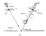
figure 1 , the scene for which shadows have to be generated is represented. The proposed method enables the generation of shadows in real-time. When a video game is played, according to the displacement of persons in a scene, guided by the user, the shadows have to be generated in real-time. Therefore, the method is advantageously executed thanks to a Graphics Processing unit, known under the acronym of GPU, on a computer or graphics processing board of a computer. The GPU will execute the software instructions to execute the method which is disclosed hereafter. The code instructions are stored on a computer-readable medium, such as a memory. - The method is based on the fact that a light source and a virtual camera are positioned in the scene. One embodiment is shown on
figure 1 . - A
virtual camera 1 captures the scene for which shadows have to be generated. A light source 2 is positioned as shown onfigure 1 . A sphere 4 is located in the scene and represents an occluding object for animage 10. The pixels are projected on asurface plane 3. The light source 2 projects light rays 5 which illuminate part of the sphere 4. Theimage 10 comprises an array of pixels that represent a three-dimensional scene as viewed from a particular point of thevirtual camera 1. For a given light source 2, adepth map 6 is computed. Thedepth map 6 includes an array of pixels, where instead of having a color value, each pixel has a depth value. Each pixel in the depth map has coordinates (xsm, ysm). In one embodiment, the depth value is defined with reference to a z-axis, which is normal to the depth-map. - The flowchart given in
figure 2 is based on a real-time shadow-mapping algorithm but it is not limited to this method and the invention can be based on any shadow mapping-based technique. - In the case of perspective shadow mapping methods, steps E2 and E7 described later on are different.
- In a step E1, a camera is positioned at the light source location, thanks to the facilities offered by virtual reality.
- In a step E2, the scene is rendered from the camera positioned at the light source location. The distance dsm (xsm, ysm), visible on
figure 1 withreference numeral 8, to each point which is visible from this camera position is stored in the shadow map. The shadow map is a depth-map texture stored in a graphics memory. - In a step E3, the rendering process is initialized and in the following steps the camera is located in its original position.
- In a step E4, the user defines the bias bbase which depends only on the scene scale. For instance, the
value 0,1 is suitable for a scene which length unit is the meter. - In a step E5 a first pixel Pix as in the final image is chosen. All the pixels will be chosen one after the others. In other embodiments, depending on the processor capabilities, several pixels can be processed simultaneously.
- In a step E6, the point P visible through pixel Pix is projected into the light space.
- In a step E7, the distance dp from P to the light source is computed. It is shown on
figure 1 as reference numeral 9. - This light ray, from the light source to the point P, crosses the depth map at pixel of coordinates (xsm, ysm) and the corresponding distance dsm (xsm, ysm) to the nearest occluder is fetched from the shadow map in a step E8.
- In a step E9, an adaptive bias is computed. As shown in
figure 4 , in conventional methods, there is aliasing on surfaces. Aliasing artifacts tend to appear when the rendered surface gets tangent to the lighting direction. - As each pixel of the shadow map stores the distance to the point visible in the middle of the pixel, the limited sampling rate yields zones in which points are successively labeled as lit or shadowed.
- To remove the artifacts, the bias value must be raised. Conversely, surfaces nearly perpendicular to the lighting direction do not require a high bias value.
- According to the present embodiment of the invention, based on the surface orientation at each visible point, a per-pixel bias adaptation function is defined. Given the user-defined base bias value bbase which only depends on the scene scale, the actual bias b used to determine the shadowing is computed according to the following equation:

- where '.' is the vector dot product operator, N is the surface normal, L is the incident light direction and ε is a minimum value, typically 0.05, to prevent the bias value to go to infinity when N gets nearly perpendicular to L.
-
Figure 3 illustrates this by showing the L and N representations. - In a step E10, a test is performed. Dp represents the distance from the light source to the point P and Dsm represents the distance from the light source to the shadow map.
- If dp ≥ dsm +b, then one moves forward to a step E11 in which the pixel Pix is labeled as a shadowed pixel.
- If dp < dsm +b, then one moves forward to a step E12 in which the pixel is labeled as a lit pixel.
- Then one moves further to step E13, in which a test is performed in order to check whether this is the last pixel of the scene. If yes, the whole scene has been processed, otherwise, one moves further to step E15, in which a next pixel is chosen and one moves back to step E6, and so on and so forth until all pixels have been reviewed (step E14).
- When all the pixels of the image have been labeled either lit or shadowed, an image processing method is performed on these pixels to respectively light or shadow them.
- The invention as described in the preferred embodiments, is advantageously computed using a Graphics processing unit (GPU) on a graphics processing board.
- The invention is also therefore implemented preferentially as software code instructions and stored on a computer-readable medium such as a memory (flash, SDRAM...), said instructions being read by a graphics processing unit.
- The foregoing description of the embodiments of the invention has been presented for the purposes of illustration and description. It is not intended to be exhaustive or to limit the invention to the precise form disclosed. Persons skilled in the relevant art can appreciate that many modifications and variations are possible in light of the above teaching. It is therefore intended that the scope of the invention is not limited by this detailed description, but rather by the claims appended hereto.
Claims (6)
- Method for generating shadows in an image (10) comprising the steps of:- Computing (E2) a depth-map (6) that comprises an array of pixels, wherein pixels in the depth-map (6) have a depth value (dsm) that indicates a depth from the light source (2) to a portion of the nearest occluding object (4) visible through the pixel,- projecting (E6) each point (Pix) visible from a virtual camera (1) into the light space,- calculating (E7) the distance (dp) between the said visible projected point (P) and the light source (2),- fetching (E8) the depth value (dsm) in the depth-map (6) corresponding to the light ray from the light source to said visible projected point (P),Characterized in that it further comprises the steps of- computing (E9), for each pixel, an adaptive bias (b) as a function of a predetermined base bias (bbase) and the orientation of the surface (3) on which the said visible point is located,- comparing (E10) for each pixel (Pix) in the image, the distance (dp) between said visible projected point (P) and the light source (2) with the sum of the corresponding depth map value ((dsm) and said adaptive bias (bbase),- labelling (E11, E12) said pixel (Pix) as lit or shadowed according to said comparison.
- Method according to claim 1 characterized in that said adaptive bias (bbase) is dependant on said surface normal (N).
- Method according to claim 2 characterized in that said adaptive bias (b) is defined as the division of said predetermined base bias (bbase) by the dot product of the surface normal (N) by the incident light direction (L).
- Method according to any of the previous claims characterized in that said adaptive bias is limited to a maximum value.
- Graphics processing unit comprising code instructions for performing the method according to any of the previous claims.
- Computer program product for computing shadows for an image, the computer program product comprising a computer-readable medium containing computer program code for performing the steps of the method according to any of claims 1 to 4.
Priority Applications (7)
| Application Number | Priority Date | Filing Date | Title |
|---|---|---|---|
| EP09364002A EP2234069A1 (en) | 2009-03-27 | 2009-03-27 | Method for generating shadows in an image |
| CN201080015184.9A CN102365657B (en) | 2009-03-27 | 2010-03-26 | Method for generating shadows in an image |
| EP10710352A EP2411967B1 (en) | 2009-03-27 | 2010-03-26 | Method for generating shadows in an image |
| JP2012501313A JP5437475B2 (en) | 2009-03-27 | 2010-03-26 | Shading generation method for images |
| PCT/EP2010/053976 WO2010109002A1 (en) | 2009-03-27 | 2010-03-26 | Method for generating shadows in an image |
| US13/138,652 US9569884B2 (en) | 2009-03-27 | 2010-03-26 | Method for generating shadows in an image |
| KR1020117022706A KR101652141B1 (en) | 2009-03-27 | 2010-03-26 | Method for generating shadows in an image |
Applications Claiming Priority (1)
| Application Number | Priority Date | Filing Date | Title |
|---|---|---|---|
| EP09364002A EP2234069A1 (en) | 2009-03-27 | 2009-03-27 | Method for generating shadows in an image |
Publications (1)
| Publication Number | Publication Date |
|---|---|
| EP2234069A1 true EP2234069A1 (en) | 2010-09-29 |
Family
ID=40853814
Family Applications (2)
| Application Number | Title | Priority Date | Filing Date |
|---|---|---|---|
| EP09364002A Withdrawn EP2234069A1 (en) | 2009-03-27 | 2009-03-27 | Method for generating shadows in an image |
| EP10710352A Active EP2411967B1 (en) | 2009-03-27 | 2010-03-26 | Method for generating shadows in an image |
Family Applications After (1)
| Application Number | Title | Priority Date | Filing Date |
|---|---|---|---|
| EP10710352A Active EP2411967B1 (en) | 2009-03-27 | 2010-03-26 | Method for generating shadows in an image |
Country Status (6)
| Country | Link |
|---|---|
| US (1) | US9569884B2 (en) |
| EP (2) | EP2234069A1 (en) |
| JP (1) | JP5437475B2 (en) |
| KR (1) | KR101652141B1 (en) |
| CN (1) | CN102365657B (en) |
| WO (1) | WO2010109002A1 (en) |
Cited By (5)
| Publication number | Priority date | Publication date | Assignee | Title |
|---|---|---|---|---|
| WO2016076932A1 (en) * | 2014-11-11 | 2016-05-19 | Intergraph Corporation | Method and apparatus for shadow estimation and spreading |
| CN106530387A (en) * | 2016-11-29 | 2017-03-22 | 国家电网公司 | Variance shadow optimization method |
| EP3097541A4 (en) * | 2014-01-22 | 2017-10-25 | Tencent Technology (Shenzhen) Company Limited | Image processing method and apparatus, and computer device |
| US10424108B2 (en) | 2017-03-03 | 2019-09-24 | Intergraph Corporation | Shadow casting for an elevation data grid |
| CN111292408A (en) * | 2020-01-21 | 2020-06-16 | 武汉大学 | Shadow generation method based on attention mechanism |
Families Citing this family (11)
| Publication number | Priority date | Publication date | Assignee | Title |
|---|---|---|---|---|
| FR2988891A1 (en) * | 2012-03-29 | 2013-10-04 | Thomson Licensing | METHOD FOR ESTIMATING OPACITY LEVEL IN A SCENE AND CORRESPONDING DEVICE |
| JP2015119277A (en) * | 2013-12-17 | 2015-06-25 | オリンパスイメージング株式会社 | Display apparatus, display method, and display program |
| US10229526B2 (en) | 2014-03-13 | 2019-03-12 | Imagination Technologies Limited | Rendering of soft shadows |
| US10083541B2 (en) | 2014-03-13 | 2018-09-25 | Imagination Technologies Limited | Object illumination in hybrid rasterization and ray traced 3-D rendering |
| CN104951036B (en) * | 2014-03-27 | 2017-12-15 | 腾讯科技(深圳)有限公司 | A kind of interface method of adjustment and terminal |
| US10311629B2 (en) | 2016-01-22 | 2019-06-04 | Intel Corporation | Level of detail selection during ray tracing |
| WO2019031259A1 (en) * | 2017-08-08 | 2019-02-14 | ソニー株式会社 | Image processing device and method |
| JP6487578B1 (en) * | 2018-01-05 | 2019-03-20 | 株式会社スクウェア・エニックス | Program, recording medium, and shadow drawing method |
| CN109447925B (en) * | 2018-09-28 | 2021-07-09 | Oppo广东移动通信有限公司 | Image processing method and device, storage medium and electronic equipment |
| CN111145330B (en) * | 2019-12-31 | 2023-06-30 | 广州方硅信息技术有限公司 | Human model rendering method and device, electronic equipment and storage medium |
| CN111815750A (en) * | 2020-06-30 | 2020-10-23 | 深圳市商汤科技有限公司 | Method and device for polishing image, electronic equipment and storage medium |
Citations (3)
| Publication number | Priority date | Publication date | Assignee | Title |
|---|---|---|---|---|
| US5742749A (en) * | 1993-07-09 | 1998-04-21 | Silicon Graphics, Inc. | Method and apparatus for shadow generation through depth mapping |
| US5870097A (en) | 1995-08-04 | 1999-02-09 | Microsoft Corporation | Method and system for improving shadowing in a graphics rendering system |
| US7119806B1 (en) * | 2000-05-31 | 2006-10-10 | Nvidia Corporation | System, method and article of manufacture for shadow mapping |
Family Cites Families (19)
| Publication number | Priority date | Publication date | Assignee | Title |
|---|---|---|---|---|
| US5377313A (en) * | 1992-01-29 | 1994-12-27 | International Business Machines Corporation | Computer graphics display method and system with shadow generation |
| US5739820A (en) * | 1992-11-19 | 1998-04-14 | Apple Computer Inc. | Method and apparatus for specular reflection shading of computer graphic images |
| US5880736A (en) | 1997-02-28 | 1999-03-09 | Silicon Graphics, Inc. | Method system and computer program product for shading |
| US6791544B1 (en) | 2000-04-06 | 2004-09-14 | S3 Graphics Co., Ltd. | Shadow rendering system and method |
| US6664963B1 (en) * | 2000-05-31 | 2003-12-16 | Nvidia Corporation | System, method and computer program product for programmable shading using pixel shaders |
| US6593923B1 (en) * | 2000-05-31 | 2003-07-15 | Nvidia Corporation | System, method and article of manufacture for shadow mapping |
| US6760024B1 (en) * | 2000-07-19 | 2004-07-06 | Pixar | Method and apparatus for rendering shadows |
| US20030076320A1 (en) * | 2001-10-18 | 2003-04-24 | David Collodi | Programmable per-pixel shader with lighting support |
| US7075530B2 (en) * | 2003-02-27 | 2006-07-11 | International Business Machines Corporation | Fast lighting processors |
| US7106326B2 (en) * | 2003-03-03 | 2006-09-12 | Sun Microsystems, Inc. | System and method for computing filtered shadow estimates using reduced bandwidth |
| CA2525977C (en) * | 2003-05-30 | 2012-06-26 | Karl Johann Schmidt | Rendering of soft shadows using depth maps |
| US7924281B2 (en) | 2005-03-09 | 2011-04-12 | Ati Technologies Ulc | System and method for determining illumination of a pixel by shadow planes |
| US7969438B2 (en) * | 2007-01-23 | 2011-06-28 | Pacific Data Images Llc | Soft shadows for cinematic lighting for computer graphics |
| US8189003B2 (en) * | 2007-05-08 | 2012-05-29 | Dreamworks Animation Llc | System and method for rendering computer graphics utilizing a shadow illuminator |
| CN101055645B (en) * | 2007-05-09 | 2010-05-26 | 北京金山软件有限公司 | A shade implementation method and device |
| JP5007633B2 (en) * | 2007-09-04 | 2012-08-22 | 株式会社セガ | Image processing program, computer-readable recording medium storing the program, image processing apparatus, and image processing method |
| CN100468462C (en) * | 2007-09-26 | 2009-03-11 | 腾讯科技(深圳)有限公司 | Shadows plotting method and rendering device thereof |
| US8471853B2 (en) * | 2007-10-26 | 2013-06-25 | Via Technologies, Inc. | Reconstructable geometry shadow mapping method |
| CN101393651A (en) * | 2008-11-07 | 2009-03-25 | 北京航空航天大学 | View field driving real-time shadow method |
-
2009
- 2009-03-27 EP EP09364002A patent/EP2234069A1/en not_active Withdrawn
-
2010
- 2010-03-26 WO PCT/EP2010/053976 patent/WO2010109002A1/en active Application Filing
- 2010-03-26 EP EP10710352A patent/EP2411967B1/en active Active
- 2010-03-26 CN CN201080015184.9A patent/CN102365657B/en active Active
- 2010-03-26 US US13/138,652 patent/US9569884B2/en active Active
- 2010-03-26 JP JP2012501313A patent/JP5437475B2/en not_active Expired - Fee Related
- 2010-03-26 KR KR1020117022706A patent/KR101652141B1/en active IP Right Grant
Patent Citations (3)
| Publication number | Priority date | Publication date | Assignee | Title |
|---|---|---|---|---|
| US5742749A (en) * | 1993-07-09 | 1998-04-21 | Silicon Graphics, Inc. | Method and apparatus for shadow generation through depth mapping |
| US5870097A (en) | 1995-08-04 | 1999-02-09 | Microsoft Corporation | Method and system for improving shadowing in a graphics rendering system |
| US7119806B1 (en) * | 2000-05-31 | 2006-10-10 | Nvidia Corporation | System, method and article of manufacture for shadow mapping |
Non-Patent Citations (4)
| Title |
|---|
| FOLEY C ET AL: "Computer graphics: principles and practice second edition (pages 721-731)", COMPUTER GRAPHICS: PRINCIPLES AND PRACTICE, XX, XX, 1 January 1996 (1996-01-01), pages 721 - 731, XP008107775 * |
| L. WILLIAMS: "Casting curved shadows on curved surfaces", SIGGRAPH, 1978 |
| M. BUNNELL; F. PELLACINI: "GPU Gems", 2004, article "Shadow Map Antialiasing" |
| SCHÜLER ET AL: "Eliminating Surface Acne with Gradient Shadow Mapping", SHADERX4. ADVANCED RENDERING TECHNIQUES, CHARLES RIVER MEDIA, INC, HINGHAM, MASSACHUSETTS, 12 January 2006 (2006-01-12), pages 289 - 297, XP009120714, ISBN: 978-1-58450-425-2 * |
Cited By (6)
| Publication number | Priority date | Publication date | Assignee | Title |
|---|---|---|---|---|
| EP3097541A4 (en) * | 2014-01-22 | 2017-10-25 | Tencent Technology (Shenzhen) Company Limited | Image processing method and apparatus, and computer device |
| WO2016076932A1 (en) * | 2014-11-11 | 2016-05-19 | Intergraph Corporation | Method and apparatus for shadow estimation and spreading |
| US9530244B2 (en) | 2014-11-11 | 2016-12-27 | Intergraph Corporation | Method and apparatus for shadow estimation and spreading |
| CN106530387A (en) * | 2016-11-29 | 2017-03-22 | 国家电网公司 | Variance shadow optimization method |
| US10424108B2 (en) | 2017-03-03 | 2019-09-24 | Intergraph Corporation | Shadow casting for an elevation data grid |
| CN111292408A (en) * | 2020-01-21 | 2020-06-16 | 武汉大学 | Shadow generation method based on attention mechanism |
Also Published As
| Publication number | Publication date |
|---|---|
| EP2411967B1 (en) | 2013-01-23 |
| US20120001911A1 (en) | 2012-01-05 |
| JP5437475B2 (en) | 2014-03-12 |
| KR101652141B1 (en) | 2016-08-29 |
| WO2010109002A1 (en) | 2010-09-30 |
| JP2012522283A (en) | 2012-09-20 |
| CN102365657A (en) | 2012-02-29 |
| EP2411967A1 (en) | 2012-02-01 |
| US9569884B2 (en) | 2017-02-14 |
| KR20120002578A (en) | 2012-01-06 |
| CN102365657B (en) | 2014-09-17 |
Similar Documents
| Publication | Publication Date | Title |
|---|---|---|
| EP2234069A1 (en) | Method for generating shadows in an image | |
| US8659593B2 (en) | Image processing apparatus, method and program | |
| US6690372B2 (en) | System, method and article of manufacture for shadow mapping | |
| US6593923B1 (en) | System, method and article of manufacture for shadow mapping | |
| US20100091018A1 (en) | Rendering Detailed Animated Three Dimensional Characters with Coarse Mesh Instancing and Determining Tesselation Levels for Varying Character Crowd Density | |
| US8207968B1 (en) | Method and apparatus for irradiance caching in computing indirect lighting in 3-D computer graphics | |
| GB2518019A (en) | Image rendering of laser scan data | |
| US7158133B2 (en) | System and method for shadow rendering | |
| WO2001009761A1 (en) | Floating-point complementary depth buffer | |
| US8040352B2 (en) | Adaptive image interpolation for volume rendering | |
| JP7038683B2 (en) | Synthesizers, methods and programs | |
| Wang et al. | Second-depth shadow mapping | |
| Jeschke et al. | Interactive smooth and curved shell mapping | |
| KR20070008707A (en) | Graphics pipeline for rendering graphics | |
| KR101118597B1 (en) | Method and System for Rendering Mobile Computer Graphic | |
| Todt et al. | Fast (spherical) light field rendering with per-pixel depth | |
| ElHelw et al. | Real-time photo-realistic rendering for surgical simulations with graphics hardware | |
| Ragragui et al. | Per-pixel revolution mapping with rectification of the texture projection | |
| Koo et al. | An efficient point rendering using octree and texture lookup | |
| Na et al. | Curved ray-casting for displacement mapping in the GPU | |
| CN117671125A (en) | Illumination rendering method, device, equipment and storage medium | |
| Palmér | Analytical motion blurred shadows | |
| KR0153664B1 (en) | 3d object generator in a graphic system | |
| Soler et al. | Hierarchical Screen Space Indirect Illumination For Video Games | |
| Yamasaki et al. | Mathematical PSNR prediction model between compressed normal maps and rendered 3D images |
Legal Events
| Date | Code | Title | Description |
|---|---|---|---|
| PUAI | Public reference made under article 153(3) epc to a published international application that has entered the european phase |
Free format text: ORIGINAL CODE: 0009012 |
|
| AK | Designated contracting states |
Kind code of ref document: A1 Designated state(s): AT BE BG CH CY CZ DE DK EE ES FI FR GB GR HR HU IE IS IT LI LT LU LV MC MK MT NL NO PL PT RO SE SI SK TR |
|
| AX | Request for extension of the european patent |
Extension state: AL BA RS |
|
| AKY | No designation fees paid | ||
| REG | Reference to a national code |
Ref country code: DE Ref legal event code: R108 Effective date: 20110503 |
|
| STAA | Information on the status of an ep patent application or granted ep patent |
Free format text: STATUS: THE APPLICATION IS DEEMED TO BE WITHDRAWN |
|
| 18D | Application deemed to be withdrawn |
Effective date: 20110330 |