EP2233954A1 - Ferrule connecting structure - Google Patents
Ferrule connecting structure Download PDFInfo
- Publication number
- EP2233954A1 EP2233954A1 EP10250501A EP10250501A EP2233954A1 EP 2233954 A1 EP2233954 A1 EP 2233954A1 EP 10250501 A EP10250501 A EP 10250501A EP 10250501 A EP10250501 A EP 10250501A EP 2233954 A1 EP2233954 A1 EP 2233954A1
- Authority
- EP
- European Patent Office
- Prior art keywords
- pair
- ferrules
- holding portion
- connecting structure
- ferrule
- Prior art date
- Legal status (The legal status is an assumption and is not a legal conclusion. Google has not performed a legal analysis and makes no representation as to the accuracy of the status listed.)
- Withdrawn
Links
- 239000013307 optical fiber Substances 0.000 claims abstract description 62
- 230000002093 peripheral effect Effects 0.000 claims abstract description 27
- 239000000835 fiber Substances 0.000 claims abstract description 12
- 230000008878 coupling Effects 0.000 claims description 21
- 238000010168 coupling process Methods 0.000 claims description 21
- 238000005859 coupling reaction Methods 0.000 claims description 21
- 238000003825 pressing Methods 0.000 claims description 20
- 238000003780 insertion Methods 0.000 claims description 9
- 230000037431 insertion Effects 0.000 claims description 9
- 210000001525 retina Anatomy 0.000 description 9
- 230000003287 optical effect Effects 0.000 description 7
- MCMNRKCIXSYSNV-UHFFFAOYSA-N Zirconium dioxide Chemical compound O=[Zr]=O MCMNRKCIXSYSNV-UHFFFAOYSA-N 0.000 description 6
- 238000010586 diagram Methods 0.000 description 5
- XEEYBQQBJWHFJM-UHFFFAOYSA-N Iron Chemical compound [Fe] XEEYBQQBJWHFJM-UHFFFAOYSA-N 0.000 description 4
- 238000013459 approach Methods 0.000 description 3
- 230000005540 biological transmission Effects 0.000 description 3
- 238000004891 communication Methods 0.000 description 3
- 238000000034 method Methods 0.000 description 3
- 238000010276 construction Methods 0.000 description 2
- 238000005520 cutting process Methods 0.000 description 2
- 229910052742 iron Inorganic materials 0.000 description 2
- 230000007246 mechanism Effects 0.000 description 2
- 239000012141 concentrate Substances 0.000 description 1
- 230000003247 decreasing effect Effects 0.000 description 1
- 230000000694 effects Effects 0.000 description 1
- 238000012423 maintenance Methods 0.000 description 1
- 238000004519 manufacturing process Methods 0.000 description 1
- 239000000463 material Substances 0.000 description 1
- 230000008569 process Effects 0.000 description 1
- 230000009467 reduction Effects 0.000 description 1
- 229910001220 stainless steel Inorganic materials 0.000 description 1
- 239000010935 stainless steel Substances 0.000 description 1
Images






Classifications
-
- G—PHYSICS
- G02—OPTICS
- G02B—OPTICAL ELEMENTS, SYSTEMS OR APPARATUS
- G02B6/00—Light guides; Structural details of arrangements comprising light guides and other optical elements, e.g. couplings
- G02B6/24—Coupling light guides
- G02B6/36—Mechanical coupling means
- G02B6/38—Mechanical coupling means having fibre to fibre mating means
- G02B6/3807—Dismountable connectors, i.e. comprising plugs
- G02B6/3873—Connectors using guide surfaces for aligning ferrule ends, e.g. tubes, sleeves, V-grooves, rods, pins, balls
- G02B6/3874—Connectors using guide surfaces for aligning ferrule ends, e.g. tubes, sleeves, V-grooves, rods, pins, balls using tubes, sleeves to align ferrules
- G02B6/3877—Split sleeves
-
- G—PHYSICS
- G02—OPTICS
- G02B—OPTICAL ELEMENTS, SYSTEMS OR APPARATUS
- G02B6/00—Light guides; Structural details of arrangements comprising light guides and other optical elements, e.g. couplings
- G02B6/24—Coupling light guides
- G02B6/36—Mechanical coupling means
- G02B6/38—Mechanical coupling means having fibre to fibre mating means
- G02B6/3807—Dismountable connectors, i.e. comprising plugs
- G02B6/381—Dismountable connectors, i.e. comprising plugs of the ferrule type, e.g. fibre ends embedded in ferrules, connecting a pair of fibres
- G02B6/3818—Dismountable connectors, i.e. comprising plugs of the ferrule type, e.g. fibre ends embedded in ferrules, connecting a pair of fibres of a low-reflection-loss type
- G02B6/3821—Dismountable connectors, i.e. comprising plugs of the ferrule type, e.g. fibre ends embedded in ferrules, connecting a pair of fibres of a low-reflection-loss type with axial spring biasing or loading means
-
- G—PHYSICS
- G02—OPTICS
- G02B—OPTICAL ELEMENTS, SYSTEMS OR APPARATUS
- G02B6/00—Light guides; Structural details of arrangements comprising light guides and other optical elements, e.g. couplings
- G02B6/24—Coupling light guides
- G02B6/36—Mechanical coupling means
- G02B6/38—Mechanical coupling means having fibre to fibre mating means
- G02B6/3807—Dismountable connectors, i.e. comprising plugs
- G02B6/381—Dismountable connectors, i.e. comprising plugs of the ferrule type, e.g. fibre ends embedded in ferrules, connecting a pair of fibres
- G02B6/3825—Dismountable connectors, i.e. comprising plugs of the ferrule type, e.g. fibre ends embedded in ferrules, connecting a pair of fibres with an intermediate part, e.g. adapter, receptacle, linking two plugs
-
- G—PHYSICS
- G02—OPTICS
- G02B—OPTICAL ELEMENTS, SYSTEMS OR APPARATUS
- G02B6/00—Light guides; Structural details of arrangements comprising light guides and other optical elements, e.g. couplings
- G02B6/24—Coupling light guides
- G02B6/36—Mechanical coupling means
- G02B6/38—Mechanical coupling means having fibre to fibre mating means
- G02B6/3807—Dismountable connectors, i.e. comprising plugs
- G02B6/3833—Details of mounting fibres in ferrules; Assembly methods; Manufacture
- G02B6/3851—Ferrules having keying or coding means
Definitions
- the present invention relates to a ferrule connecting structure for use in connecting a pair of optical fibers.
- ferrule connecting structure ferrules in which the optical fibers are provided individually are opposed to each other and connected with each other.
- a ferrule 101 includes, as shown in Fig. 10 , a centering portion 102, a cylindrical body 103 and a flange portion 104 which is formed on the body.
- the body 103 includes a press fit opening 105 into which the centering portion 102 is press fitted.
- An optical fiber is exposed only by a predetermined length with a jacket at a leading end thereof stripped off.
- the exposed optical fiber stock is inserted into an optical fiber insertion hole 106.
- a jacketed optical fiber cable is inserted into an optical fiber cable insertion hole 107.
- an optical connector used in the field of communication includes a split sleeve.
- An optical fiber is provided in each of a pair of ferrules 101.
- Centering portions 102 of the ferrules 101 are aligned in an axial direction within the split sleeve. End faces of the centering portions 102 are opposed to each other and connected with each other.
- a working person fits a rotating tool in rotational tool receiving cutouts provided on a flange portion 104 with the pair of ferrules opposed to each other and connected with each other in the split sleeve. Then, by rotating the rotating tool, the eccentricity of one with respect to the other of the pair of optical fibers is minutely adjusted.
- the pair of optical fibers are connected together concentrically by connecting and aligning one with the other of the pair of optical fibers.
- the split sleeve is forcibly expanded by the centering portion 102 of each ferrule 101. Then, the split sleeve exhibits an elastic restoring force and supports the ferrules 101 under the elastic restoring force.
- bonding the connecting portion between the pair of ferrules 101 is considered as a solution.
- the connecting portion between the pair of ferrules 101 is bonded, the following problems are caused.
- a portion or device of the apparatus which is coupled to the ferrules 101 or ferrules 101 need to be replaced.
- the working person needs to cut apart once the ferrules 101.
- the working person needs to insert new optical fibers through the ferrules 101.
- the working person needs to bond a connecting portion of a pair of ferrules 101 again. In this way, some labor hours are required to replace devices coupled to ferrules or ferrules themselves.
- An object of the invention is to provide a ferrule connecting structure which requires as few labor hours as possible in replacing devices coupled to ferrules or ferrules themselves.
- another object of the invention is to provide a ferrule connecting structure which can maintain a holding condition of ferrules after assemblage of the ferrule connecting structure in an ensured fashion and can maintain high light coupling efficiency.
- one aspect of the invention provides a ferrule connecting structure for optically connecting a pair of fibers which are provided in a pair of ferrules, respectively, the ferrule connecting structure comprising a first holding portion, an peripheral portion, a second holding portion, a third holding portion and a fourth holding portion.
- the first holding portion holds the pair of ferrules in a state that end faces of the pair of ferrules are opposed to each other and connected with each other.
- the peripheral portion is provided on at least one of the pair of ferrules and which includes a peripheral surface on which a plurality of groove portions are formed.
- the second holding portion is configured to fit in the groove portion so as to hole a rotating position of the ferrule about an axis of the optical fiber.
- the third holding portion is configured to be detachably attached to the first holding portion so as to press the first holding portion by elastic force in a direction intersecting with the axis.
- the fourth holding portion presses the pair of ferrules in a direction in which the end faces of the pair of ferrules approach each other by elastic force.
- a second aspect of the invention provides the ferrule connecting structure according to the first aspect, wherein the peripheral surface of the peripheral portion has a shape in which the plurality of groove portions and a plurality of projecting portions are formed alternately.
- a third aspect of the invention provides the ferrule connecting structure according to the second aspect, wherein the number of the plurality of groove portions is predetermined based on an light coupling efficiency of the optical fibers.
- a fourth aspect of the invention provides the ferrule connecting structure according to the first aspect, wherein the peripheral portion is provided on both of the pair of ferrules.
- a fifth aspect of the invention provides the ferrule connecting structure according to the first aspect, wherein the third holding portion includes an accommodating portion having an accommodating space for accommodating the first holding portion, and the accommodating portion comprises:
- a sixth aspect of the invention provides the ferrule connecting structure according to the fifth aspect, wherein the fourth holding portion includes:
- a seventh aspect of the invention provides the ferrule connecting structure according to the sixth aspect, wherein the extending portion includes a confronting portion which confronts the groove portion when the third holding portion is accommodated in the accommodating space ,and the second holding portion includes a protrusion which is formed on the confronting surface of the extending portion, and wherein the protrusion is configured to fit in the groove portion.
- An eighth aspect of the invention provides the ferrule connecting structure according to the fifth aspect, wherein the peripheral portions are provided on both of the pair of ferrules, respectively, and the second holding portion, the third holding portion and the fourth holding portion are combined as an unit.
- a ninth aspect of the invention provides the ferrule connecting structure according to the first aspect, wherein the first holding portion is a split sleeve.
- a tenth aspect of the invention provides the ferrule connecting structure according to the first aspect, wherein the third holding portion presses the first holding portion in a direction perpendicular to the axis.
- An eleventh aspect of the invention provides the ferrule connecting structure according to the fifth aspect, wherein the first surface extends parallel to the axis, the second surface is perpendicular to the first surface, and wherein the second surface extends parallel to the axis, and the curved surface extends parallel to the axis.
- a ferrule connecting structure 1 according to an embodiment of the invention will be described.
- Fig. 3 shows only one flange 8a
- a flange 8b has the same construction as that of the flange 8a.
- the ferrule connecting structure 1 includes a pair of ferrules 2a, 2b, a split sleeve 3 and a clamp 4.
- an axial direction of a pair of ferrules 2a, 2b is defined as X axis, and directions which intersects with X axis as Y axis and Z axis.
- the definition of the directions of X axis, Y axis and Z axis is understood to be common with respect to the other drawings.
- the pair of ferrules 2a, 2b includes bodies 5a, 5b and centering portions 6a, 6b.
- the bodies 5a, 5b are made of a stainless steel, and the centering portions 6a, 6b are made of zirconia.
- the pair of ferrules 2a, 2b are connected in such a state that end faces of the centering portions 6a, 6b are connected with each other within the split sleeve 3.
- the body 5a includes a press fit opening 7a in which the centering portion 6a is press fitted.
- the body 5a includes a flange 8a.
- the centering portion 6a includes an optical fiber insertion hole 9a through which an optical fiber stock is inserted.
- the body 5a includes an optical fiber cable insertion hole 10a through which a jacketed optical fiber cable is inserted.
- the flange 8a has a gearwheel shape in which grooves 11a and projecting portions 12 are aligned alternately along an outer circumference of the flange 8a.
- the centering portion 6b includes an optical fiber insertion hole through which an optical fiber stock is inserted.
- the body5b also includes a press fit opening in which the centering portion 6b is press fitted and includes a flange 8b and an optical fiber cable insertion hole through which an optical fiber cable is inserted.
- the flange 8b has, as shown in Fig. 6 , a gearwheel shape in which grooves 11b and projecting portions 12b are aligned alternately along an outer circumference thereof.
- the split sleeve 3 has a configuration in which a longitudinal slit is provided in a cylindrical tube.
- the split sleeve is made of zirconia and has elasticity.
- the split sleeve wraps a portion where the centering portions 6a, 6b of the pair of ferrules 2a, 2b are opposed to each other and connected with each other. Then, when the split sleeve 3 wraps to hold the portion where the centering portions 6a, 6b are so connected, an inside diameter portion of the split sleeve 3 is elastically deformed so as to forcibly be expanded and maintains the condition in which the pair of ferrules 2a, 2b are opposed to each other and connected with each other by virtue of elastic force thereof.
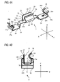
- the clamp 4 includes, as shown in Fig. 4A , a holding portion 13, a pressing portion 14 and protrusions 15a, 15b.
- the clamp 4 is made of iron and has elasticity.
- the clamp 4 is formed through pressing.
- the holding portion 13 includes a first plate portion 16, a second plate portion 17 and a third plate portion 18.
- the first plate portion 16, the second plate portion 17 and the third plate portion 18 form an accommodating space 19 which can accommodate therein the split sleeve 3.
- the split sleeve 3 is accommodated in the accommodating space 19 through open end portions 20.
- the first plate portion 16 includes a first flat surface 21 which extends parallel to an X axis.
- the first flat surface 21 contacts with a peripheral surface of the split sleeve 3 when the split sleeve 3 is accommodated in the accommodating space 19.
- the second plate portion 17 includes a second flat surface 22 which is formed to stand vertically on one side end 16a of the first plate portion 16.
- the second flat surface 22 is configured to contact with the circumferential surface of the split sleeve 3 when the split sleeve 3 is accommodated in the accommodating space 19.
- the third plate portion 18 stands on the other side end 16b of the first plate portion 16 to project towards the second plate portion 17.
- the third plate portion 18 includes a curved surface 23 which extends parallel to the X axis. The curved surface 23 projects towards the second plate portion 17 and contacts with the peripheral surface of the split sleeve 3 when the split sleeve 3 is accommodated within the accommodating space 19.
- the operation and function of the holding portion 13 when the split sleeve 3 is accommodated in the accommodating space 19 through the open end portions 20 will be described.
- the first flat surface 21 and the second flat surface 22 function as a reference plane and the position of the split sleeve 3 within the accommodating space 19 is determined.
- the third plate portion 18 is elastically deformed to expand in a direction at right angles to the X axis when the split sleeve 2 is accommodated in the accommodating space 19. As this occurs, the curved surface 23 contacts with the peripheral surface of the split sleeve 3.. Then, with the split sleeve 3 accommodated completely in the accommodating space 19, elastic force works, and the third plate portion 18 moves to be returned to its initial condition.
- the pair of ferrules 2a, 2b are opposed to each other and connected with each other within the sleeve 3, and as shown in Fig. 7A , an axis AXa of the ferrule 2a and an axis AXb of the ferrule 2b coincide with each other to constitute a single axis AX.
- the split sleeve 3 is accommodated completely in the accommodating space 19, the split sleeve 3 is pressed towards the X axis, that is, in a direction VT perpendicular to the AX of the pair of ferrules 2a, 2b by the elastic force of the third plate portion 18 while in abutment with the curved surface 23 and is held in that position.
- the pressing portion 14 includes extending portions 24 and pressing pieces 25a, 25b.
- the extending portions 24 extend in the X-axis direction from opposite sides in the X-axis direction of the holding portion 13 while being bent into a step-like configuration.
- the pressing pieces 25a, 25b are formed to stand on the extending portions 24.
- the pressing pieces 25a, 25b include projecting portions 26a, 26b and cutout portions 27a, 27b, respectively.
- the projecting portions 26a, 26b each have a shape in which each projecting portion is bifurcated at its free end side.
- the cutout portions 27a, 27b are formed between bifurcated free end portions of the projecting portions 26a, 26b, respectively.
- the operation and function of the pressing portion 14 will be described when the split sleeve 3 is accommodated in the accommodating space 19 with the pair of ferrules connected with each other within the split sleeve 3.
- the projecting portions 26a, 26b contact with side surfaces of the flanges 8a, 8b, respectively, when the split sleeve 3 is accommodated in the accommodating space 19 as shown in Fig. 1B .
- the flanges 8a, 8b being pressed by elastic force in the X-axis direction, the pair of ferrules 2a, 2b are held.
- the cutout portions 27a, 27b permit insertion of the centering portions 6a, 6b of the pair of ferrules 2a, 2b therethrough.
- the protrusions 15a, 15b are formed on confronting surface of the extending portions 24 which confront grooves 11a, 11b when the split sleeve 3 is accommodated in the accommodating space 19.
- the protrusions 15a, 15b are fitted in the grooves 11a, 11b of the flanges 8a, 8b, respectively.
- the rotating positions of the flanges 8a, 8b are determined.
- the fitting of the protrusions 15a, 15b in the grooves 11a, 11b, respectively, will be described in detail later.
- Figs. 7A to 7C show simplified constructions of the ferrules 2a, 2b and the split sleeve 3 with bodies 5a, 5b omitted.
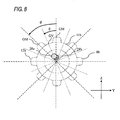
- Fig. 8 shows only the flange 8b for the sake of simplification of the drawing.
- Fig.8 shows the flange portion 8b which includes eight grooves 11b and eight projecting portion 12b.
- the numbers of grooves 11a are 16. So are the numbers of grooves 11b and projecting portions 12a, 12b.
- the pair of ferrules 2a, 2b are opposed to each other within the split sleeve 3, and the axis AXa of the ferrule 2a and the axis AXb of the ferrule 2a coincide with each other so as to constitute the single axis AX.
- Fig. 7B shows rotating positions of the optical fibers 28a, 28b about respective core centers Ma, Mb thereof with respect to the axis AX when the ferrule 2a and the ferrule 2b are seen about the axis AX of respective.
- the optical fibers 28a, 28b have respective core eccentricity amounts Ca, Cb ( ⁇ m) in accordance with the eccentricity of the respective core centers Ma, Mb from the axis AX. Assuming that an angle from the core center Mb to the core center Ma is ⁇ , an axis deviation amount AD ( ⁇ m) of the pair of optical fibers 28a, 28b is calculated from the follow equation.
- AD Ca 2 + Cb 2 - 2 ⁇ Ca ⁇ Cb ⁇ cos ⁇ 1 / 2
- connection loss CL in connection of optical fibers having the same mode field diameter is calculated by the following equation.
- MFD the mode field diameter
- BR denotes a beam radius ( ⁇ m) which is defined as a half amount of MFD.
- a connection loss CL of the optical fibers 28a, 28b is calculated by a measuring system shown in Fig. 7C .
- Fig. 7C light from a light source 29 is supplied into the ferrule connection mechanism 1 and is then supplied to an optical power meter 30 via the optical fibers 28a, 28b.
- an optical power detected by the optical power meter 30 varies in accordance with the connection loss CL of the optical fibers 28a, 28b. Consequently, the connection loss CL of the optical fibers 28a, 28b can be calculated from the optical power detected by the optical power meter 30.
- the working person can identify a position having a least connection loss CL in a positional relationship between the ferrule 2a and the ferrule 2b by measuring a connection loss CL by the measuring system shown in Fig. 7C when carrying out an alignment of the ferrules 2a, 2b.
- the working person causes the split sleeve 3 to be accommodated in the accommodating space 19 in the position having the least connection loss CL, whereby by the protrusions 15a, 15b fitting in the grooves 11a, 11b, respectively, the rotating positions of the flanges 8a, 8b are determined.
- the ferrule 2a and the ferrule 2b are held in the position having the least connection loss CL, that is, a position having a largest connection efficiency CE.
- a relationship between the numbers GN of grooves 11a, 11b and the connection loss CL will be described when the pair of ferrules 2a, 2b are opposed to each other and connected with each other within the split sleeve 3 and the split sleeve 3 is accommodated within the accommodating space 19.
- a relationship between the number GN of grooves 11b and an interval between the grooves 11b of the flange 8b, that is, a rotational angle ⁇ from a crest portion GM of the projecting portion 12b to an adjacent crest portion GM is expressed by the following equation.
- connection loss CL becomes largest either when the core center Ma is positioned at a crest portion GM of the projecting portion 12a and the core center Mb is positioned at a root portion GV of the groove portion 11b or when the core center Mb is positioned at the crest portion GM of the projecting portion 12b and the core center Ma is positioned at a root portion GV of the groove 11a.
- a relationship between the angle ⁇ from the core center Mb to the core center Ma and the rotational angle ⁇ of the pair of ferrules 2a, 2b is expressed as follows.
- Equation 6 When substituting Equation 1 by Equation 2 and Equation 5, Equation 6 is obtained which expresses a connection loss CL (dB) and the numbers GN of grooves 11a, 11b when the connection loss CL becomes largest.
- Fig. 9 The result of a calculation of an light coupling efficiency CE using Equation 6 is shown in Fig. 9 .
- MFD of the optical fibers 28a, 28b thee types of set values are used which include a visible light single mode fiber whose MFD is 3.5 ⁇ m, a communication single mode fiber whose MFD is 10.0 ⁇ m and a multiple mode fiber whose MFD is 100.0 ⁇ m.
- an axis of abscissa represents the numbers GN of grooves 11a, 11b and an axis of ordinates represents the light coupling efficiency CE (%).
- the communication single mode fiber and the multiple mode fiber it is seen that a larger light coupling efficiency CE can be obtained as the numbers GN of grooves 11a, 11b increase.
- the connection efficiency takes a small value of the order of 50%. This is because the connection loss CL becomes large due to MFD of the visible light single mode fiber taking the very small value compared with those of the other two optical fibers.
- the visible light single mode fiber as shown in Fig.
- the connection efficiency CE takes a larger value of 90% or lager.
- the working person performs a calculation using Equation 6 in advance and provides the numbers GN of grooves 11a, 11b which can obtain an light coupling efficiency of 90% or lager on the flanges 8a, 8b, thereby making it possible to obtain a high connection efficiency CE.
- 16 grooves 11a, 11b are provided individually on the flanges 8a, 8b, so as to obtain an light coupling efficiency of almost 100%.
- the pair of ferrules 2a, 2b include the flanges 8a, 8b which are provided with the numbers GN of grooves 11a, 11b set according to the method described above.
- the pair of ferrules 2a, 2b are opposed to each other and connected with each other in the split sleeve 3.
- the optical fibers 28a, 28b which are provided in the ferrules 2a, 2b, respectively are optically connected together.
- connection loss CL Aligning the pair of ferrules 2a, 2b will be described.
- a calculation of a connection loss CL is carried out based on the method described above using the measuring system shown in Fig. 7C . Specifically, a position having a least connection loss CL, that is, a position having a largest light coupling efficiency is identified while rotating the pair of ferrules 2a, 2b within the split sleeve 3, and the pair of ferrules 2a, 2b are held in that position within the split sleeve 3, whereby the alignment of the pair of ferrules 2a, 2b is completed.
- the split sleeve 3 is accommodated within the accommodating space 19 in the clamp 4 with the pair of ferrules 2a, 2b kept opposed to each other and connected with each other within the split sleeve 3 after the alignment of the ferrules has been completed.
- the split sleeve 3 is accommodated within the accommodating space 19 in the clamp 4, there may occur such a situation that the protrusions 15a, 15b on the clamp 4 do not fit in the corresponding grooves 11a, 11b on the flanges 8a, 8b but are brought into contact with the projecting portions 12a, 12b of the flanges 8a, 8b.
- the protrusions 15a, 15b are caused to deviate slightly from the projecting portions 12a, 12b while kept in contact therewith, whereby the protrusions 15a, 15b are caused to fit in the corresponding grooves 11a, 11b. Since the numbers GN of grooves 11a, 11b on the flanges 8a, 8b are set in advance so as to obtain a large light coupling efficiency CE, the slight deviation of the projecting portions 12a, 12b from the protrusions 15a, 15b after contact affects little the light coupling efficiency CE.
- the protrusions 15a, 15b are fitted in the corresponding grooves 11a, 11b of the clamp 4, and the flanges 8a, 8b are pressed in the direction in which the pair of ferrules 2a, 2b are opposed to each other and connected with each other by the pressing portion 14, whereby assembling work of assembling the pair of ferrules 2a, 2b in the split sleeve 3 and on to the clamp 4 is completed.
- Disassembling work of the ferrule connecting structure 1 will be carried out as follows.
- the working person grips on the split sleeve 3 and the clamp 4 with both of his or her hands to remove the split sleeve 3 from the accommodating space 19 of the clamp 4.
- the working person grips on the split sleeve 3 and the body 5a of the ferrule 2a to pull the ferrule 2a out of the split sleeve 3.
- the working person pulls the ferrule 2b out of the split sleeve 3.
- the disassembling work of the ferrule connecting structure can be implemented extremely easily without carrying out labor hour consuming work of cutting apart the optical fibers 28a, 28b.
- a retina scanning display is one form of a head-mounted display device.
- the retina scanning display is mounted on a head portion of a person who wears it or in the vicinity of the head portion so as to guide an image light to the eyes of the person who wears the same display.
- the retina scanning display is configured so that by scanning the retina in two-dimensional directions thereover, an image corresponding to contents information is visualized by the person who wears the retina scanning display.
- the retina display system includes a light source part, a light transmission part and a wave combining part.
- the light source unit includes three image light generating portions which generate individually respective image lights including red, blue and green lights.
- the light transmission part is provided one for each of the image light generating part.
- the light transmission part includes a condensing lens, the pair of ferrules, a light source portion side optical fiber 28a and a wave combining part side optical fiber 28b.
- the condensing lens concentrates the image light emitted from the image light generating portion on to the optical fiber 28a.
- the optical fiber 28a is provided within the ferrule 2a.
- the optical fiber 28b is provided in the ferrule 2b.
- the image light concentrated to the optical fiber 28a by the condensing lens is supplied to the wave combining part via the optical fibers 28a, 28b.
- the wave combining part combines the image lights which are supplied via the respective optical fibers 28a, 28b.
- the ferrule connecting structure 1 is used in connecting a centering portion 6a of a ferrule 2a which is provided at a leading end of the three units with a centering portion 6b of a ferrule 2b which is connected with a wave combining part.
- the ferrule connecting structure 1 is disassembled in the way described above for replace of the failed light source part as a unit.
- the following labor consuming work has to be carried out in which the optical fibers are cut apart, the wave combining part is removed from the housing, the optical fiber 28b at the wave combining part is passed through a new ferrule 2b, and leading ends of the ferrules 2a, 2b are ground, thereafter, the ferrules 2a, 2b being bonded together again.
- the light source part, the condensing lens and the optical fiber 28 are not assembled as a unit, in addition to the work described above, some labor hours have to be spent in inserting the optical fiber 28a on the light source part side through the ferrule 2a.
- the optical fibers are cut every time light source parts are replaced, there is caused a problem that the optical fibers get shorter every replacement.
- the ferrule connecting structure 1 according to the embodiment to the retina scanning display, the labor hours do not have to be spent which would otherwise be required for the pair of ferrules 2a, 2b which are bonded together, and the working person is allowed to easily replace the failed light source part.
- the rotating positions of the ferrules 2a, 2b about the axis AX of the optical fibers 28a, 28b are held by the protrusions 15a, 15b.
- the split sleeve 3 is pressed in the direction in which the split sleeve 3 approaches vertically the axis AX by the holding portion 13.
- the pair of ferrules 2a, 2b are pressed in the direction in which the connecting end faces of the pair of ferrules 2a, 2b confront each other by the pressing portion 14.
- the pair of ferrules 2a, 2b is held while confronting each other from two directions, the direction perpendicular to the axis AX by the holding portion 13 and the direction in which the connecting end faces of the pair ferrules 2a, 2b are opposed to each other and connected with each other by the pressing portion 14. Therefore, the holding condition after assembling of the ferrule connecting structure 1 is maintained in an ensured fashion.
- the rotating positions of the ferrules 2a, 2b around the axis AX of the optical fibers 28a, 28b are set finely in accordance with the numbers GN of groove 11a, 11b provided on the flanges 8a, 8b.
- the numbers GN of grooves 11a, 11b are determined in advance based on the light coupling efficiency of the optical fibers 28a, 28b. Thus, desired light coupling efficiency CE is obtained.
- the flanges 8a, 8b are provided on the pair of ferrules 2a, 2b, respectively.
- the rotating positions are set for both of the pair of ferrules 2a, 2b and the rotating positions so set are then held. Consequently, the high light coupling efficiency CE is obtained in a more ensured fashion. Accordingly, the high light coupling efficiency is maintained in a more ensured fashion.
- the split sleeve 3 is pressed to be held by the third plate portion 18 in such a state that the split sleeve 3 is positioned in the predetermined position by the first surface 21 and the second surface 22 within the accommodating space 19. Consequently, the holding of the split sleeve 3 is ensured, thereby making it possible to prevent an abrupt movement of the split sleeve 3 after assemblage of the ferrule connecting structure.
- the working person can insert the ferrules 2a, 2b in the cutout portion while maintaining the condition in which the pair of ferrules 2a, 2b are left opposed to each other and connected with each other within the split sleeve 3. Consequently, the pressing portion 14 can be mounted on the flanges 8a, 8b without any problem.
- the working person can fit the protrusions 15a, 15b in the grooves 11a, 11b of the flanges 8a, 8b which the protrusion 15a, 15b confront when the split sleeve 3 is accommodated within the accommodating space 19 with the pair of ferrules 2a, 2b made to confront each other within the split sleeve 3. Consequently, the working person can easily achieve the maintenance of the condition in which the pair of ferrules 2a, 2b are made to confront each other and the setting of the rotating positions of the ferrules 2a, 2b.
- the protrusions 15a, 15b, the third holding portion 13 and the pressing portion 14 are combined as an integral unit. Consequently, the fabrication process is simplified and a reduction in costs can be realized.
- the holding members which are combined as an unit is mounted on the ferrules 2a, 2b. Consequently, three different holding actions are completed simultaneously, whereby the holding work by the working person becomes simple and easy.
- the holding portion 13, the pressing portion 14 and the protrusions 15a, 15bb are fabricated integrally, the invention is not limited thereto.
- any of those members may be formed as a separate member, or all these members may be formed as separate members.
- only the holding portion 13 is formed as a separate member, which is configured to be mounted on the extending portion 24 of the pressing portion 14.
- the split sleeve 3 is made of zirconia and the clamp 4 of iron, the invention is not limited thereto. Any material may be used as long as it is a member having elasticity.
- the invention is not limited thereto.
- the flanges 8a, 8b may be formed separately from the bodies 5a, 5b. As this occurs, the working person needs to perform work of bonding the flanges 8a, 8b to the bodies 5a, 5b, respectively.
- flanges 8a, 8b are provided on both of the pair of ferrules 2a, 2b, the invention is not limited thereto.
- a flange may be provided only either of the pair of ferrules 2a, 2b.
- the numbers GN of grooves 11a, 11b are 16.
- the invention is not limited thereto.
- the numbers of grooves 11a, 11b may be, for example, 10 or 20, provided that relatively high light coupling efficiency is obtained.
- the holding portion 13 includes the first plate portion 16 the second plate portion 17 and the third plate portion 18 and the split sleeve 3 is held by these three members
- the invention is not limited thereto.
- the holding portion 13 may include another third plate portion, not shown, in place of the second plate portion 17.
- the split sleeve 3 is pressed in a direction in which the split sleeve 3 approaches vertically the axis AX of the pair of ferrules 2a, 2b by the elastic force of the third plate portion 18 and the additional third plate portion and is then held in that position.
Landscapes
- Physics & Mathematics (AREA)
- General Physics & Mathematics (AREA)
- Optics & Photonics (AREA)
- Mechanical Coupling Of Light Guides (AREA)
Abstract
A ferrule connecting structure (1) for optically connecting a pair of fibers (28a,b) which are provided in a pair of ferrules (2a,2b), respectively, the ferrule connecting structure comprises: a first holding portion (3) which holds the pair of ferrules; a peripheral portion (8a,8b) which is provided on the pair of ferrules and which includes a plurality of groove portions (11a,11b); a second holding portion (15a,15b) which is fit in the groove portion so as to hold the ferrule in a particular rotating position about an axis (Ax) of the optical fiber; a third holding portion (13) which is detachably attached to the first holding portion so as to press the first holding portion in a direction intersecting with the axis; and a fourth holding portion (14) which presses the pair of ferrules in a direction in which the end faces of the pair of ferrules are opposed to each other.
Description
- The present invention relates to a ferrule connecting structure for use in connecting a pair of optical fibers. In the ferrule connecting structure, ferrules in which the optical fibers are provided individually are opposed to each other and connected with each other.
- An example of a conventional ferrule is shown in
Fig. 10 . Conventionally, aferrule 101 includes, as shown inFig. 10 , acentering portion 102, acylindrical body 103 and aflange portion 104 which is formed on the body. Thebody 103 includes a press fit opening 105 into which thecentering portion 102 is press fitted. An optical fiber is exposed only by a predetermined length with a jacket at a leading end thereof stripped off. The exposed optical fiber stock is inserted into an opticalfiber insertion hole 106. A jacketed optical fiber cable is inserted into an optical fibercable insertion hole 107. - As disclosed in
JP-A-2001-215360 ferrules 101. Centeringportions 102 of theferrules 101 are aligned in an axial direction within the split sleeve. End faces of the centeringportions 102 are opposed to each other and connected with each other. Then, a working person fits a rotating tool in rotational tool receiving cutouts provided on aflange portion 104 with the pair of ferrules opposed to each other and connected with each other in the split sleeve. Then, by rotating the rotating tool, the eccentricity of one with respect to the other of the pair of optical fibers is minutely adjusted. The pair of optical fibers are connected together concentrically by connecting and aligning one with the other of the pair of optical fibers. The split sleeve is forcibly expanded by thecentering portion 102 of eachferrule 101. Then, the split sleeve exhibits an elastic restoring force and supports theferrules 101 under the elastic restoring force. - However, only with the pair of
ferrules 101 simply supported by the slit sleeve, in the event that the connecting portion between the pair offerrules 101 is loosened even a little after assemblage, there is caused a problem that it becomes difficult to obtain high light coupling efficiency. - In this case, bonding the connecting portion between the pair of
ferrules 101 is considered as a solution. However, in the event that the connecting portion between the pair offerrules 101 is bonded, the following problems are caused. In the event that part of an apparatus which utilizes the ferrule connection mechanism fails, a portion or device of the apparatus which is coupled to theferrules 101 orferrules 101 need to be replaced. As this occurs, firstly, the working person needs to cut apart once theferrules 101. Next, the working person needs to insert new optical fibers through theferrules 101. Then, the working person needs to bond a connecting portion of a pair offerrules 101 again. In this way, some labor hours are required to replace devices coupled to ferrules or ferrules themselves. - The invention has been made with a view to solving the problem. An object of the invention is to provide a ferrule connecting structure which requires as few labor hours as possible in replacing devices coupled to ferrules or ferrules themselves. In addition, another object of the invention is to provide a ferrule connecting structure which can maintain a holding condition of ferrules after assemblage of the ferrule connecting structure in an ensured fashion and can maintain high light coupling efficiency.
- In order to achieve the object, one aspect of the invention provides a ferrule connecting structure for optically connecting a pair of fibers which are provided in a pair of ferrules, respectively, the ferrule connecting structure comprising a first holding portion, an peripheral portion, a second holding portion, a third holding portion and a fourth holding portion. The first holding portion holds the pair of ferrules in a state that end faces of the pair of ferrules are opposed to each other and connected with each other. The peripheral portion is provided on at least one of the pair of ferrules and which includes a peripheral surface on which a plurality of groove portions are formed. The second holding portion is configured to fit in the groove portion so as to hole a rotating position of the ferrule about an axis of the optical fiber. The third holding portion is configured to be detachably attached to the first holding portion so as to press the first holding portion by elastic force in a direction intersecting with the axis. The fourth holding portion presses the pair of ferrules in a direction in which the end faces of the pair of ferrules approach each other by elastic force.
- A second aspect of the invention provides the ferrule connecting structure according to the first aspect, wherein the peripheral surface of the peripheral portion has a shape in which the plurality of groove portions and a plurality of projecting portions are formed alternately.
- A third aspect of the invention provides the ferrule connecting structure according to the second aspect, wherein the number of the plurality of groove portions is predetermined based on an light coupling efficiency of the optical fibers.
- A fourth aspect of the invention provides the ferrule connecting structure according to the first aspect, wherein the peripheral portion is provided on both of the pair of ferrules.
- A fifth aspect of the invention provides the ferrule connecting structure according to the first aspect, wherein
the third holding portion includes an accommodating portion having an accommodating space for accommodating the first holding portion, and
the accommodating portion comprises: - a first plate portion which has a first surface, wherein the first surface extends along the axis and is configured to contact with a peripheral surface of the first holding portion;
- a second plate portion which has a second surface, wherein the second surface stands on one side end of the first plate portion, wherein the second surface extends along the axis, and wherein the second surface is configured to contact with the peripheral surface of the fist holding portion; and
- a third plate portion which has a curved surface, wherein the curved surface stands on the other side end of the first plate portion, wherein the curved surface projects toward the second surface, and wherein the curved surface extends along the axis, and wherein the curved surface is configured to contact with the peripheral surface of the first holding portion.
- A sixth aspect of the invention provides the ferrule connecting structure according to the fifth aspect, wherein
the fourth holding portion includes: - a pair of extending portions which extend from both sides of the accommodating portion along the axis; and
- a pair of pressing pieces which stands on the pair of extending portions respectively, wherein the pair of pressing pieces is configured to contact with side surfaces of the pair of peripheral portions to press the pair of peripheral portions provided on both of the pair of ferrules in the direction in which end faces of the pair of ferrules are opposed to each other, and
- each of the pair of pressing pieces includes a cutout portion which permits insertion of the ferrule when the first holding portion is accommodated within the accommodating space.
- A seventh aspect of the invention provides the ferrule connecting structure according to the sixth aspect, wherein
the extending portion includes a confronting portion which confronts the groove portion when the third holding portion is accommodated in the accommodating space ,and
the second holding portion includes a protrusion which is formed on the confronting surface of the extending portion, and wherein the protrusion is configured to fit in the groove portion. - An eighth aspect of the invention provides the ferrule connecting structure according to the fifth aspect, wherein
the peripheral portions are provided on both of the pair of ferrules, respectively, and
the second holding portion, the third holding portion and the fourth holding portion are combined as an unit. - A ninth aspect of the invention provides the ferrule connecting structure according to the first aspect, wherein the first holding portion is a split sleeve.
- A tenth aspect of the invention provides the ferrule connecting structure according to the first aspect, wherein the third holding portion presses the first holding portion in a direction perpendicular to the axis.
- An eleventh aspect of the invention provides the ferrule connecting structure according to the fifth aspect, wherein
the first surface extends parallel to the axis,
the second surface is perpendicular to the first surface, and wherein the second surface extends parallel to the axis, and
the curved surface extends parallel to the axis. -
-
Fig. 1A is a perspective view showing an external appearance of aferrule connecting structure 1 according to an embodiment of the invention. -
Fig. 1B is a front view showing the external appearance of theferrule connecting structure 1. -
Fig. 2 is a sectional view of aferrule 2a according to the embodiment. -
Fig. 3 is a partially cutaway perspective view showing aflange 8a alone which is removed from abody 5a according to the embodiment. -
Fig. 4A is a perspective view of aclamp 4 according to the embodiment. -
Fig. 4B is a side view of theclamp 4. -
Fig. 4C is a front view of theclamp 4. -
Fig. 5 is an explanatory diagram which explains an elastic force exerted on asplit sleeve 3 when thesplit sleeve 3 is accommodated within anaccommodating space 19. -
Fig. 6 is a sectional view of theferrule connecting structure 1 taken along the line A-A shown inFig. 1(b) . -
Fig. 7A is a diagram showing a condition in which a pair offerrules split sleeve 3. -
Fig. 7B is an explanatory diagram which explains a relationship between an angle θ from a core center Mb of anoptical fiber 28b to a core center Ma of anoptical fiber 28a of the embodiment and an axis deviation amount between the pair of optical fibers. -
Fig. 7C is an explanatory diagram which explains a measuring system of a connection loss CL according to the embodiment. -
Fig. 8 is an explanatory diagram which explains a positional relationship between aflange 8b according to the embodiment and theoptical fibers -
Fig. 9 is a graph showing a relationship between light coupling efficiency CE according to the embodiment andgrooves -
Fig. 10 is a sectional view of aconventional ferrule 101. - Hereinafter, an embodiment of the invention will be described with reference to the drawings.
- Referring to the drawings, an external appearance of a
ferrule connecting structure 1 according to an embodiment of the invention will be described. AlthoughFig. 3 shows only oneflange 8a, aflange 8b has the same construction as that of theflange 8a. - As shown in
Figs. 1A, 1B , theferrule connecting structure 1 includes a pair offerrules split sleeve 3 and aclamp 4. Hereinafter, for the sake of simplification, as shown inFig. 1A , an axial direction of a pair offerrules - The pair of
ferrules bodies portions bodies portions Figs. 1A, 1B , the pair offerrules portions split sleeve 3. As shown inFig. 2 , thebody 5a includes a press fit opening 7a in which the centeringportion 6a is press fitted. As shown inFigs. 1A, 1B and2 , thebody 5a includes aflange 8a. As shown inFig. 2 , the centeringportion 6a includes an opticalfiber insertion hole 9a through which an optical fiber stock is inserted. Thebody 5a includes an optical fibercable insertion hole 10a through which a jacketed optical fiber cable is inserted. As shown inFig. 3 , theflange 8a has a gearwheel shape in whichgrooves 11a and projecting portions 12 are aligned alternately along an outer circumference of theflange 8a. As with the centeringportion 6a, the centeringportion 6b includes an optical fiber insertion hole through which an optical fiber stock is inserted. As with thebody 5a, the body5b also includes a press fit opening in which the centeringportion 6b is press fitted and includes aflange 8b and an optical fiber cable insertion hole through which an optical fiber cable is inserted. As with theflange 8a, theflange 8b has, as shown inFig. 6 , a gearwheel shape in whichgrooves 11b and projectingportions 12b are aligned alternately along an outer circumference thereof. - The
split sleeve 3 has a configuration in which a longitudinal slit is provided in a cylindrical tube. The split sleeve is made of zirconia and has elasticity. The split sleeve wraps a portion where the centeringportions ferrules split sleeve 3 wraps to hold the portion where the centeringportions split sleeve 3 is elastically deformed so as to forcibly be expanded and maintains the condition in which the pair offerrules - The
clamp 4 includes, as shown inFig. 4A , a holdingportion 13, apressing portion 14 andprotrusions clamp 4 is made of iron and has elasticity. Theclamp 4 is formed through pressing. - The holding
portion 13 includes afirst plate portion 16, asecond plate portion 17 and athird plate portion 18. Thefirst plate portion 16, thesecond plate portion 17 and thethird plate portion 18 form anaccommodating space 19 which can accommodate therein thesplit sleeve 3. Thesplit sleeve 3 is accommodated in theaccommodating space 19 throughopen end portions 20. - The
first plate portion 16 includes a firstflat surface 21 which extends parallel to an X axis. The firstflat surface 21 contacts with a peripheral surface of thesplit sleeve 3 when thesplit sleeve 3 is accommodated in theaccommodating space 19. Thesecond plate portion 17 includes a secondflat surface 22 which is formed to stand vertically on oneside end 16a of thefirst plate portion 16. The secondflat surface 22 is configured to contact with the circumferential surface of thesplit sleeve 3 when thesplit sleeve 3 is accommodated in theaccommodating space 19. Thethird plate portion 18 stands on theother side end 16b of thefirst plate portion 16 to project towards thesecond plate portion 17. Thethird plate portion 18 includes acurved surface 23 which extends parallel to the X axis. Thecurved surface 23 projects towards thesecond plate portion 17 and contacts with the peripheral surface of thesplit sleeve 3 when thesplit sleeve 3 is accommodated within theaccommodating space 19. - The operation and function of the holding
portion 13 when thesplit sleeve 3 is accommodated in theaccommodating space 19 through theopen end portions 20 will be described. When thesplit sleeve 3 is accommodated within theaccommodating space 19, the firstflat surface 21 and the secondflat surface 22 function as a reference plane and the position of thesplit sleeve 3 within theaccommodating space 19 is determined. Thethird plate portion 18 is elastically deformed to expand in a direction at right angles to the X axis when the split sleeve 2 is accommodated in theaccommodating space 19. As this occurs, thecurved surface 23 contacts with the peripheral surface of thesplit sleeve 3.. Then, with thesplit sleeve 3 accommodated completely in theaccommodating space 19, elastic force works, and thethird plate portion 18 moves to be returned to its initial condition. - The pair of
ferrules sleeve 3, and as shown inFig. 7A , an axis AXa of theferrule 2a and an axis AXb of theferrule 2b coincide with each other to constitute a single axis AX. When thesplit sleeve 3 is accommodated completely in theaccommodating space 19, thesplit sleeve 3 is pressed towards the X axis, that is, in a direction VT perpendicular to the AX of the pair offerrules third plate portion 18 while in abutment with thecurved surface 23 and is held in that position. - As shown in
Fig. 4C , thepressing portion 14 includes extendingportions 24 andpressing pieces portions 24 extend in the X-axis direction from opposite sides in the X-axis direction of the holdingportion 13 while being bent into a step-like configuration. Thepressing pieces portions 24. As shown inFigs. 4A, 4B , thepressing pieces portions cutout portions Fig. 4A , the projectingportions Fig. 4A , thecutout portions portions - The operation and function of the
pressing portion 14 will be described when thesplit sleeve 3 is accommodated in theaccommodating space 19 with the pair of ferrules connected with each other within thesplit sleeve 3. The projectingportions flanges split sleeve 3 is accommodated in theaccommodating space 19 as shown inFig. 1B . Then, by theflanges ferrules cutout portions portions ferrules - As shown in
Fig. 6 , theprotrusions portions 24 which confrontgrooves split sleeve 3 is accommodated in theaccommodating space 19. Theprotrusions grooves flanges protrusions grooves flanges protrusions grooves - For the sake of simplification of the drawing,
Figs. 7A to 7C show simplified constructions of theferrules split sleeve 3 withbodies Fig. 8 shows only theflange 8b for the sake of simplification of the drawing. For the sake of simplification of the drawing,Fig.8 shows theflange portion 8b which includes eightgrooves 11b and eight projectingportion 12b. However, in the embodiment shown inFig. 3 , the numbers ofgrooves 11a are 16. So are the numbers ofgrooves 11b and projectingportions - As shown in
Fig. 7A , the pair offerrules split sleeve 3, and the axis AXa of theferrule 2a and the axis AXb of theferrule 2a coincide with each other so as to constitute the single axis AX. -
Fig. 7B shows rotating positions of theoptical fibers ferrule 2a and theferrule 2b are seen about the axis AX of respective. Theoptical fibers optical fibers -

- When the pair of
ferrules optical fibers -

- A connection loss CL of the
optical fibers Fig. 7C . InFig. 7C , light from alight source 29 is supplied into theferrule connection mechanism 1 and is then supplied to anoptical power meter 30 via theoptical fibers light source 29 kept constant, an optical power detected by theoptical power meter 30 varies in accordance with the connection loss CL of theoptical fibers optical fibers optical power meter 30. The working person can identify a position having a least connection loss CL in a positional relationship between theferrule 2a and theferrule 2b by measuring a connection loss CL by the measuring system shown inFig. 7C when carrying out an alignment of theferrules split sleeve 3 to be accommodated in theaccommodating space 19 in the position having the least connection loss CL, whereby by theprotrusions grooves flanges ferrule 2a and theferrule 2b are held in the position having the least connection loss CL, that is, a position having a largest connection efficiency CE. - Referring to
Fig. 8 , a relationship between the numbers GN ofgrooves ferrules split sleeve 3 and thesplit sleeve 3 is accommodated within theaccommodating space 19. As shown inFig. 8 , a relationship between the number GN ofgrooves 11b and an interval between thegrooves 11b of theflange 8b, that is, a rotational angle Φ from a crest portion GM of the projectingportion 12b to an adjacent crest portion GM is expressed by the following equation. -

- The connection loss CL becomes largest either when the core center Ma is positioned at a crest portion GM of the projecting
portion 12a and the core center Mb is positioned at a root portion GV of thegroove portion 11b or when the core center Mb is positioned at the crest portion GM of the projectingportion 12b and the core center Ma is positioned at a root portion GV of thegroove 11a. In either case, as shown inFig. 8 , a relationship between the angle θ from the core center Mb to the core center Ma and the rotational angle Φ of the pair offerrules -

- When substituting
Equation 4 byEquation 3, -

- When substituting
Equation 1 by Equation 2 andEquation 5, Equation 6 is obtained which expresses a connection loss CL (dB) and the numbers GN ofgrooves -

- The result of a calculation of an light coupling efficiency CE using Equation 6 is shown in
Fig. 9 . As MFD of theoptical fibers Fig. 9 , an axis of abscissa represents the numbers GN ofgrooves optical fibers - As shown in
Fig. 9 , in any case of the visible light single mode fiber, the communication single mode fiber and the multiple mode fiber, it is seen that a larger light coupling efficiency CE can be obtained as the numbers GN ofgrooves grooves Fig. 9 , in the event that the numbers GN ofgrooves grooves flanges grooves flanges - The operation of the
ferrule connecting structure 1 according to the embodiment will be described by use of the drawings. The pair offerrules flanges grooves ferrules split sleeve 3. Theoptical fibers ferrules - Aligning the pair of
ferrules Fig. 7C . Specifically, a position having a least connection loss CL, that is, a position having a largest light coupling efficiency is identified while rotating the pair offerrules split sleeve 3, and the pair offerrules split sleeve 3, whereby the alignment of the pair offerrules - The
split sleeve 3 is accommodated within theaccommodating space 19 in theclamp 4 with the pair offerrules split sleeve 3 after the alignment of the ferrules has been completed. When thesplit sleeve 3 is accommodated within theaccommodating space 19 in theclamp 4, there may occur such a situation that theprotrusions clamp 4 do not fit in thecorresponding grooves flanges portions flanges portions protrusions protrusions portions protrusions corresponding grooves grooves flanges portions protrusions protrusions corresponding grooves clamp 4, and theflanges ferrules pressing portion 14, whereby assembling work of assembling the pair offerrules split sleeve 3 and on to theclamp 4 is completed. - Disassembling work of the
ferrule connecting structure 1 will be carried out as follows. The working person grips on thesplit sleeve 3 and theclamp 4 with both of his or her hands to remove thesplit sleeve 3 from theaccommodating space 19 of theclamp 4. Next, the working person grips on thesplit sleeve 3 and thebody 5a of theferrule 2a to pull theferrule 2a out of thesplit sleeve 3. Next, similarly, the working person pulls theferrule 2b out of thesplit sleeve 3. In this way, the disassembling work of the ferrule connecting structure can be implemented extremely easily without carrying out labor hour consuming work of cutting apart theoptical fibers - An application of the
ferrule connecting structure 1 according to the invention to a retina scanning display will be described. A retina scanning display is one form of a head-mounted display device. The retina scanning display is mounted on a head portion of a person who wears it or in the vicinity of the head portion so as to guide an image light to the eyes of the person who wears the same display. The retina scanning display is configured so that by scanning the retina in two-dimensional directions thereover, an image corresponding to contents information is visualized by the person who wears the retina scanning display. - The retina display system includes a light source part, a light transmission part and a wave combining part. The light source unit includes three image light generating portions which generate individually respective image lights including red, blue and green lights. The light transmission part is provided one for each of the image light generating part. The light transmission part includes a condensing lens, the pair of ferrules, a light source portion side
optical fiber 28a and a wave combining part sideoptical fiber 28b. The condensing lens concentrates the image light emitted from the image light generating portion on to theoptical fiber 28a. Theoptical fiber 28a is provided within theferrule 2a. Theoptical fiber 28b is provided in theferrule 2b. The image light concentrated to theoptical fiber 28a by the condensing lens is supplied to the wave combining part via theoptical fibers optical fibers - When the light source part fails, it is extremely difficult to replace only the failed light source portion within a housing of the retina scanning display and thereafter align the optical axis of a replacement light source part. Because of this, normally, a light source part for each image light, a condensing lens and an
optical fiber 28a are assembled individually as one unit in advance. Then, theferrule connecting structure 1 is used in connecting a centeringportion 6a of aferrule 2a which is provided at a leading end of the three units with a centeringportion 6b of aferrule 2b which is connected with a wave combining part. By adopting this configuration, when the light source part fails, requiring the light source part to be replaced, theferrule connecting structure 1 is disassembled in the way described above for replace of the failed light source part as a unit. In contrast to this, in the event that theferrules optical fiber 28b at the wave combining part is passed through anew ferrule 2b, and leading ends of theferrules ferrules optical fiber 28a on the light source part side through theferrule 2a. In the event that the optical fibers are cut every time light source parts are replaced, there is caused a problem that the optical fibers get shorter every replacement. However, by applying theferrule connecting structure 1 according to the embodiment to the retina scanning display, the labor hours do not have to be spent which would otherwise be required for the pair offerrules - The rotating positions of the
ferrules optical fibers protrusions split sleeve 3 is pressed in the direction in which thesplit sleeve 3 approaches vertically the axis AX by the holdingportion 13. The pair offerrules ferrules pressing portion 14. - Consequently, the pair of
ferrules portion 13 and the direction in which the connecting end faces of thepair ferrules pressing portion 14. Therefore, the holding condition after assembling of theferrule connecting structure 1 is maintained in an ensured fashion. - The rotating positions of the
ferrules protrusions - As a result, even in the event that the connecting portion between the pair of
ferrules optical fibers ferrules ferrules - The rotating positions of the
ferrules optical fibers groove flanges - The numbers GN of
grooves optical fibers - The
flanges ferrules ferrules - The
split sleeve 3 is pressed to be held by thethird plate portion 18 in such a state that thesplit sleeve 3 is positioned in the predetermined position by thefirst surface 21 and thesecond surface 22 within theaccommodating space 19. Consequently, the holding of thesplit sleeve 3 is ensured, thereby making it possible to prevent an abrupt movement of thesplit sleeve 3 after assemblage of the ferrule connecting structure. - The working person can insert the
ferrules ferrules split sleeve 3. Consequently, thepressing portion 14 can be mounted on theflanges - The working person can fit the
protrusions grooves flanges protrusion split sleeve 3 is accommodated within theaccommodating space 19 with the pair offerrules split sleeve 3. Consequently, the working person can easily achieve the maintenance of the condition in which the pair offerrules ferrules - The
protrusions portion 13 and thepressing portion 14 are combined as an integral unit. Consequently, the fabrication process is simplified and a reduction in costs can be realized. In addition, compared with the ferrule connecting structure in which such three holding members are configured as separate members, the holding members which are combined as an unit is mounted on theferrules - In the embodiment, while the holding
portion 13, thepressing portion 14 and theprotrusions 15a, 15bb are fabricated integrally, the invention is not limited thereto. For example, any of those members may be formed as a separate member, or all these members may be formed as separate members. For example, only the holdingportion 13 is formed as a separate member, which is configured to be mounted on the extendingportion 24 of thepressing portion 14. - In the embodiment, while the
split sleeve 3 is made of zirconia and theclamp 4 of iron, the invention is not limited thereto. Any material may be used as long as it is a member having elasticity. - In the embodiment, while the
flanges flanges bodies flanges bodies - In the embodiment, while the
flanges ferrules ferrules - In the embodiment, the numbers GN of
grooves grooves - In the embodiment, while the holding
portion 13 includes thefirst plate portion 16 thesecond plate portion 17 and thethird plate portion 18 and thesplit sleeve 3 is held by these three members, the invention is not limited thereto. For example, the holdingportion 13 may include another third plate portion, not shown, in place of thesecond plate portion 17. As this occurs, when thesplit sleeve 3 is accommodated in theaccommodating space 19, thesplit sleeve 3 is pressed in a direction in which thesplit sleeve 3 approaches vertically the axis AX of the pair offerrules third plate portion 18 and the additional third plate portion and is then held in that position.
Claims (11)
- A ferrule connecting structure for optically connecting a pair of fibers which are provided in a pair of ferrules, respectively, the ferrule connecting structure comprising:a first holding portion which holds the pair of ferrules in a state that end faces of the pair of ferrules are opposed to each other and connected with each other;a peripheral portion which is provided on at least one of the pair of ferrules and which includes an peripheral surface on which a plurality of groove portions are formed;a second holding portion which is configured to fit in the groove portion so as to hold the ferrule in a particular rotating position about an axis of the optical fiber;a third holding portion which is configured to be detachably attached to the first holding portion so as to press the first holding portion by elastic force in a direction which intersects with the axis; anda fourth holding portion which presses the pair of ferrules by elastic force in a direction in which the end faces of the pair of ferrules are opposed to each other.
- The ferrule connecting structure according to claim 1, wherein the peripheral surface of the peripheral portion has a shape in which the plurality of groove portions and a plurality of projecting portions are formed alternately.
- The ferrule connecting structure according to claim 2, wherein the number of the plurality of groove portions is predetermined based on an light coupling efficiency of the optical fibers.
- The ferrule connecting structure according to any one of claims 1 to 3, wherein the peripheral portion is provided on both of the pair of ferrules.
- The ferrule connecting structure according to any one of claims 1 to 3, wherein
the third holding portion includes an accommodating portion having an accommodating space for accommodating the first holding portion, and
the accommodating portion comprises:a first plate portion which has a first surface, wherein the first surface extends along the axis and is configured to contact with a peripheral surface of the first holding portion;a second plate portion which has a second surface, wherein the second surface stands on one side end of the first plate portion, wherein the second surface extends along the axis, and wherein the second surface is configured to contact with the peripheral surface of the fist holding portion; anda third plate portion which has a curved surface, wherein the curved surface stands on the other side end of the first plate portion, wherein the curved surface projects toward the second surface, and wherein the curved surface extends along the axis, and wherein the curved surface is configured to contact with the peripheral surface of the first holding portion. - The ferrule connecting structure according to claim 5, wherein
the fourth holding portion includes:a pair of extending portions which extend from both sides of the accommodating portion along the axis; anda pair of pressing pieces which stands on the pair of extending portions respectively, wherein the pair of pressing pieces is configured to contact with side surfaces of the pair of peripheral portions to press the pair of peripheral portions provided on both of the pair of ferrules in the direction in which end faces of the pair of ferrules are opposed to each other, andeach of the pair of pressing pieces includes a cutout portion which permits insertion of the ferrule when the first holding portion is accommodated within the accommodating space. - The ferrule connecting structure according to claim 6, wherein
the extending portion includes a confronting portion which confronts the groove portion when the third holding portion is accommodated in the accommodating space ,and
the second holding portion includes a protrusion which is formed on the confronting surface of the extending portion, and wherein the protrusion is configured to fit in the groove portion. - The ferrule connecting structure according to claim 5, wherein
the peripheral portions are provided on both of the pair of ferrules, respectively, and
the second holding portion, the third holding portion and the fourth holding portion are combined as an unit. - The ferrule connecting structure according to any one of claims 1 to 3, wherein the first holding portion is a split sleeve.
- The ferrule connecting structure according to any one of claims 1 to 3, wherein the third holding portion presses the first holding portion in a direction perpendicular to the axis.
- The ferrule connecting structure according to claim 5, wherein
the first surface extends parallel to the axis,
the second surface is perpendicular to the first surface, and wherein the second surface extends parallel to the axis, and
the curved surface extends parallel to the axis.
Applications Claiming Priority (1)
| Application Number | Priority Date | Filing Date | Title |
|---|---|---|---|
| JP2009073438A JP2010224353A (en) | 2009-03-25 | 2009-03-25 | Ferrule connection mechanism |
Publications (1)
| Publication Number | Publication Date |
|---|---|
| EP2233954A1 true EP2233954A1 (en) | 2010-09-29 |
Family
ID=42271682
Family Applications (1)
| Application Number | Title | Priority Date | Filing Date |
|---|---|---|---|
| EP10250501A Withdrawn EP2233954A1 (en) | 2009-03-25 | 2010-03-18 | Ferrule connecting structure |
Country Status (3)
| Country | Link |
|---|---|
| US (1) | US20100247040A1 (en) |
| EP (1) | EP2233954A1 (en) |
| JP (1) | JP2010224353A (en) |
Cited By (1)
| Publication number | Priority date | Publication date | Assignee | Title |
|---|---|---|---|---|
| EP0472527B1 (en) * | 1989-05-19 | 1994-03-16 | Siemens Aktiengesellschaft | Valve choke, especially for high-voltage dc transmission systems |
Families Citing this family (9)
| Publication number | Priority date | Publication date | Assignee | Title |
|---|---|---|---|---|
| JP5868629B2 (en) * | 2011-08-02 | 2016-02-24 | オリンパス株式会社 | Light source device |
| US10191226B2 (en) | 2013-01-23 | 2019-01-29 | Commscope, Inc. Of North Carolina | Cylindrical optical ferrule alignment apparatus |
| US9256033B2 (en) * | 2013-01-23 | 2016-02-09 | Commscope, Inc. Of North Carolina | Cylindrical optical ferrule alignment apparatus |
| JP5983456B2 (en) * | 2013-02-15 | 2016-08-31 | 日立金属株式会社 | Ferrule fixing member |
| US9453974B2 (en) * | 2014-07-24 | 2016-09-27 | Verizon Patent And Licensing Inc. | Eccentric cut sleeve for optical fiber adapter |
| JP2017138535A (en) | 2016-02-05 | 2017-08-10 | 富士通コンポーネント株式会社 | Ferrule connection parts |
| US10591681B2 (en) * | 2017-07-13 | 2020-03-17 | Nest Technical Services, Inc. | Multichannel fiber optic connector, adapter, and contact retention method |
| WO2019216431A1 (en) * | 2018-05-11 | 2019-11-14 | Sumitomo Electric Industries, Ltd. | Optical connector, optical module and clip member |
| CN112987188B (en) * | 2019-12-13 | 2025-08-29 | 连讯通信(天津)有限公司 | Fiber Optic Connectors |
Citations (6)
| Publication number | Priority date | Publication date | Assignee | Title |
|---|---|---|---|---|
| US4741590A (en) * | 1982-09-07 | 1988-05-03 | Amp Incorporated | Fiber optic connector |
| EP0636910A1 (en) * | 1993-07-30 | 1995-02-01 | AT&T Corp. | Quasi-hermaphroditic-type optical fiber connection |
| US6095694A (en) * | 1998-05-11 | 2000-08-01 | Nuvisions International, Inc. | Fiber optic component coupling apparatus with locking capability and methods of fabrication and use thereof |
| JP2001215360A (en) | 2000-01-31 | 2001-08-10 | Fujitsu Takamisawa Component Ltd | Plastic ferrule and its manufacturing method |
| US20030081909A1 (en) * | 2001-10-12 | 2003-05-01 | Junji Taira | Ferrule |
| EP1443350A2 (en) * | 2003-01-30 | 2004-08-04 | Panduit Corporation | Tunable fiber optic connector |
Family Cites Families (2)
| Publication number | Priority date | Publication date | Assignee | Title |
|---|---|---|---|---|
| US2809004A (en) * | 1954-10-06 | 1957-10-08 | Kaufman Joseph | Holders for electronic components |
| US5390269A (en) * | 1992-12-23 | 1995-02-14 | Methode Electronics, Inc. | Fiber optic connector with high resolution tunable fiber holder |
-
2009
- 2009-03-25 JP JP2009073438A patent/JP2010224353A/en active Pending
-
2010
- 2010-03-16 US US12/725,050 patent/US20100247040A1/en not_active Abandoned
- 2010-03-18 EP EP10250501A patent/EP2233954A1/en not_active Withdrawn
Patent Citations (6)
| Publication number | Priority date | Publication date | Assignee | Title |
|---|---|---|---|---|
| US4741590A (en) * | 1982-09-07 | 1988-05-03 | Amp Incorporated | Fiber optic connector |
| EP0636910A1 (en) * | 1993-07-30 | 1995-02-01 | AT&T Corp. | Quasi-hermaphroditic-type optical fiber connection |
| US6095694A (en) * | 1998-05-11 | 2000-08-01 | Nuvisions International, Inc. | Fiber optic component coupling apparatus with locking capability and methods of fabrication and use thereof |
| JP2001215360A (en) | 2000-01-31 | 2001-08-10 | Fujitsu Takamisawa Component Ltd | Plastic ferrule and its manufacturing method |
| US20030081909A1 (en) * | 2001-10-12 | 2003-05-01 | Junji Taira | Ferrule |
| EP1443350A2 (en) * | 2003-01-30 | 2004-08-04 | Panduit Corporation | Tunable fiber optic connector |
Cited By (1)
| Publication number | Priority date | Publication date | Assignee | Title |
|---|---|---|---|---|
| EP0472527B1 (en) * | 1989-05-19 | 1994-03-16 | Siemens Aktiengesellschaft | Valve choke, especially for high-voltage dc transmission systems |
Also Published As
| Publication number | Publication date |
|---|---|
| US20100247040A1 (en) | 2010-09-30 |
| JP2010224353A (en) | 2010-10-07 |
Similar Documents
| Publication | Publication Date | Title |
|---|---|---|
| US20100247040A1 (en) | Ferrule connecting structure | |
| JP3515305B2 (en) | Optical connector | |
| JP5759183B2 (en) | Optical connector and assembly method thereof | |
| US7534051B2 (en) | Optical fiber connector, optical fiber connecting method, and connector converter | |
| TW513585B (en) | Fiber optic connector | |
| US20030215191A1 (en) | Angle-PC connector | |
| EP2933665A1 (en) | Optical connector | |
| JP4951029B2 (en) | Optical connector adapter and optical connector | |
| WO2012172869A1 (en) | Optical fiber connection method and optical fiber connection structure | |
| JP2795539B2 (en) | Improvements on optical fiber connectors | |
| US8175431B2 (en) | Multi-core ferrule and optical fiber connection structure | |
| JP2019066772A (en) | Optical connector and optical coupling structure | |
| JP7606008B2 (en) | Ferrule retention structure | |
| US20210041640A1 (en) | Optical fiber connectors for rotational alignment | |
| JPH11337771A (en) | Optical connector for multi-core fiber | |
| CN103582835A (en) | Optical connector | |
| US8388237B2 (en) | Optical connector and method of assembling optical connector | |
| CN87104804A (en) | Connector for detachable connection of light conducting fibres | |
| JP2012252202A (en) | Multicore optical fiber connector | |
| JP4192751B2 (en) | Optical fiber connector and optical fiber connection method | |
| JPH11160579A (en) | Optical connector | |
| JP2593551B2 (en) | Connector for multi-core optical fiber batch connection | |
| JP2022067426A (en) | Optical connector and optical connector manufacturing method | |
| WO2019189312A1 (en) | Optical connector and optical connection structure | |
| JP2004151296A (en) | Optical fiber connection method and connection structure |
Legal Events
| Date | Code | Title | Description |
|---|---|---|---|
| PUAI | Public reference made under article 153(3) epc to a published international application that has entered the european phase |
Free format text: ORIGINAL CODE: 0009012 |
|
| 17P | Request for examination filed |
Effective date: 20100318 |
|
| AK | Designated contracting states |
Kind code of ref document: A1 Designated state(s): AT BE BG CH CY CZ DE DK EE ES FI FR GB GR HR HU IE IS IT LI LT LU LV MC MK MT NL NO PL PT RO SE SI SK SM TR |
|
| AX | Request for extension of the european patent |
Extension state: AL BA ME RS |
|
| STAA | Information on the status of an ep patent application or granted ep patent |
Free format text: STATUS: THE APPLICATION IS DEEMED TO BE WITHDRAWN |
|
| 18D | Application deemed to be withdrawn |
Effective date: 20131001 |