EP2233883A1 - Method and apparatus of measuring positional variation of rotation center line - Google Patents
Method and apparatus of measuring positional variation of rotation center line Download PDFInfo
- Publication number
- EP2233883A1 EP2233883A1 EP10157602A EP10157602A EP2233883A1 EP 2233883 A1 EP2233883 A1 EP 2233883A1 EP 10157602 A EP10157602 A EP 10157602A EP 10157602 A EP10157602 A EP 10157602A EP 2233883 A1 EP2233883 A1 EP 2233883A1
- Authority
- EP
- European Patent Office
- Prior art keywords
- sample
- center line
- rotation center
- microscope
- positional variation
- Prior art date
- Legal status (The legal status is an assumption and is not a legal conclusion. Google has not performed a legal analysis and makes no representation as to the accuracy of the status listed.)
- Withdrawn
Links
- 238000000034 method Methods 0.000 title claims description 26
- 238000003384 imaging method Methods 0.000 claims abstract description 16
- 230000003287 optical effect Effects 0.000 claims description 16
- 238000005259 measurement Methods 0.000 abstract description 26
- 238000005286 illumination Methods 0.000 description 13
- 238000006073 displacement reaction Methods 0.000 description 11
- 238000010586 diagram Methods 0.000 description 4
- 230000002093 peripheral effect Effects 0.000 description 4
- 230000005540 biological transmission Effects 0.000 description 2
- VYZAMTAEIAYCRO-UHFFFAOYSA-N Chromium Chemical compound [Cr] VYZAMTAEIAYCRO-UHFFFAOYSA-N 0.000 description 1
- 229910052782 aluminium Inorganic materials 0.000 description 1
- XAGFODPZIPBFFR-UHFFFAOYSA-N aluminium Chemical compound [Al] XAGFODPZIPBFFR-UHFFFAOYSA-N 0.000 description 1
- PCHJSUWPFVWCPO-UHFFFAOYSA-N gold Chemical compound [Au] PCHJSUWPFVWCPO-UHFFFAOYSA-N 0.000 description 1
- 229910052737 gold Inorganic materials 0.000 description 1
- 239000010931 gold Substances 0.000 description 1
- 238000003754 machining Methods 0.000 description 1
- 238000012423 maintenance Methods 0.000 description 1
- 229910052751 metal Inorganic materials 0.000 description 1
- 239000002184 metal Substances 0.000 description 1
- 238000007740 vapor deposition Methods 0.000 description 1
Images


Classifications
-
- G—PHYSICS
- G01—MEASURING; TESTING
- G01B—MEASURING LENGTH, THICKNESS OR SIMILAR LINEAR DIMENSIONS; MEASURING ANGLES; MEASURING AREAS; MEASURING IRREGULARITIES OF SURFACES OR CONTOURS
- G01B11/00—Measuring arrangements characterised by the use of optical techniques
- G01B11/26—Measuring arrangements characterised by the use of optical techniques for measuring angles or tapers; for testing the alignment of axes
- G01B11/27—Measuring arrangements characterised by the use of optical techniques for measuring angles or tapers; for testing the alignment of axes for testing the alignment of axes
- G01B11/272—Measuring arrangements characterised by the use of optical techniques for measuring angles or tapers; for testing the alignment of axes for testing the alignment of axes using photoelectric detection means
-
- B—PERFORMING OPERATIONS; TRANSPORTING
- B23—MACHINE TOOLS; METAL-WORKING NOT OTHERWISE PROVIDED FOR
- B23Q—DETAILS, COMPONENTS, OR ACCESSORIES FOR MACHINE TOOLS, e.g. ARRANGEMENTS FOR COPYING OR CONTROLLING; MACHINE TOOLS IN GENERAL CHARACTERISED BY THE CONSTRUCTION OF PARTICULAR DETAILS OR COMPONENTS; COMBINATIONS OR ASSOCIATIONS OF METAL-WORKING MACHINES, NOT DIRECTED TO A PARTICULAR RESULT
- B23Q17/00—Arrangements for observing, indicating or measuring on machine tools
- B23Q17/24—Arrangements for observing, indicating or measuring on machine tools using optics or electromagnetic waves
Definitions
- the present invention relates to a method and an apparatus of measuring positional variation (run-out) of a rotation center line of one of various types of rotators often used in machine tools, electronic devices, and the like.
- a method and an apparatus suitable to measure the positional variation of a rotation center line of a rotator requiring high rotary accuracy such as a main spindle of a precision machine tool are related.
- a two-point method or a three-point method has been known.
- plural displacement meters are arranged along the outer peripheral surface of the rotator (a method in which two displacement meters are arranged is referred to as the two-point method, and a method in which three displacement meters are arranged is referred to as the three-point method)
- the positional variation of the main spindle peripheral surface accompanied with the rotation of the rotator is measured by means of each displacement meter
- the positional variation of the rotation center line of the rotator is calculated on the basis of the measurement data by means of each displacement meter (refer to JP-A-06-229751 , JP-A-06-235422 , and JP-A-10-015705 ).
- the positional variation amount of the rotation center line of the rotator may be measured two-dimensionally.
- the plural displacement meters is used, in case that there are differences in property (for example, temperature property) between the displacement meters, errors caused by the differences in the property are produced between the measurement data of the displacement meters, with the result that it is difficult to obtain the measurement results having high accuracy.
- the invention has been made in view of such the circumstances, and an object of the invention is to provide a method and an apparatus of measuring positional variation of a rotation center line, which are capable of measuring the positional variation of the rotation center line accompanied with the rotation of a sample with high accuracy.
- a positional variation measuring method which measures a positional variation of a rotation center line of a sample accompanied with a rotation of the sample, which provides a microscope arranged so that an optical axis of an objective lens and the rotation center line become parallel to each other, and so that the rotation center line is located in the observed area of the microscope, and a position indicator that is set on the sample so as to be capable of rotating in the observed area integrally with the sample, and magnified with the microscope to be observed, comprises the steps of: rotating the sample to measure the positional variation of the rotation center line of the sample; picking up respectively magnified images of the position indicator formed through the objective lens at plural time points during the rotation of the sample; finding a movement locus in an imaging coordinate system of the magnified images picked up; and calculating the position variation amount of the rotation center line on the basis of the found movement locus.
- a positional variation measuring apparatus which measures a positional variation of a rotation center line of a sample accompanied with a rotation of the sample
- the apparatus comprises: a microscope arranged so that an optical axis of an objective lens and the rotation center line become parallel to each other, and so that the rotation center line is located in an observed area of the microscope; at least one position indicator which is set on the sample so as to be capable of rotating in the observed area integrally with the sample, and magnified with the microscope to be observed; an imaging unit which picks up respectively magnified images of the position indicator formed through the objective lens at plural time points during the rotation of the sample; and an analysis unit which finds a movement locus in an imaging coordinate system of the magnified images picked up, and calculates a position variation amount of the rotation center line on the basis of the found movement locus.
- the plurality of position indicators are arranged in the observed area of the microscope.
- the rotation center line is defined as a line which is not fixed in space but fixed in the sample.
- the movement locus of the position indicator set in the sample becomes circular in case that there is no positional variation of the rotation center line, and becomes, in case that there is the positional variation, the shape out of the circle in response to the variation amount.
- the magnified image of the position indicator is picked up by means of the microscope, and the movement locus of the position indicator is found on the basis of this magnified image, the even tiny variation of the movement locus may be captured. Accordingly, it is possible to obtain the positional variation amount of the rotation center line with the high accuracy.
- the microscope is used as the only measurement system, which is different from the method in which the plural displacement meters is used as each measurement system. Therefore, there is no fear of errors caused by difference in property between the measurement systems.
- An apparatus of measuring positional variation of a rotation center line shown in Fig. 1 (which may be hereinafter referred to as an "apparatus in this embodiment") is used to measure and analyze the positional variation amount of a rotation center line A of a sample 5 (for example, a main spindle of a lathe machine) accompanied with the rotation of the sample 5, which includes a microscope 1, an analysis device 2 as an analysis unit, and a measurement jig 3 placed and fixed onto a leading end surface 5a of the sample 5.
- the rotation center line A of the sample 5 is treated as what is fixed to the sample 5, and the leading end surface 5a of the sample 5 is formed perpendicularly to the rotation center line A.
- the above microscope 1, as shown in Fig. 1 is composed of an epi-illumination optical system 10A and an observation optical system 10B.
- the epi-illumination optical system 10A of these systems includes a light source 11, a collector lens 12, an aperture stop AS, a field stop FS, a field lens 13, a half mirror 14, and an objective lens 15.
- the epi-illumination optical system 10A is constituted so as to illuminate light beam outputted from the light source 11 onto the measurement jig 3 as illumination light.
- the observation optical system 10B includes the objective lens 15 used also in the epi-illumination optical system 10A, an imaging lens 16, an imaging camera 17 as an image pick-up unit.
- the observation optical system 10B is constituted so as to form a magnified image of an observational object (in the apparatus in this embodiment, a position indicator 32 described later) in an observed area of the microscope 1, onto a two-dimensional image sensor 18 (composed of CCD, CMOS, and the like) of the imaging camera 17 by the objective lens 15 and the imaging lens 16, and pick up this magnified image by the imaging camera 17.
- a two-dimensional image sensor 18 composed of CCD, CMOS, and the like
- the above analysis device 2 is constituted by a computer or the like which performs image processing and various operational processing.
- the analysis device 2 includes a memory device which stores various programs, such as a hard disc, and a CPU which performs various operational processing, and also includes a movement locus calculating part 21 constituted by the CPU and the programs in the memory, and a positional variation calculation part 22 (refer to Fig. 2 ).
- the above measurement jig 3, as shown in Fig. 3 includes a base plate 31, and a position indicator 32 formed in the vicinity of a center point C of the base plate 31.
- This position indicator 32 is constituted by a metal film of gold, aluminum, chrome, or the like formed on the base plate 31 by vapor deposition. Further, the size of this position indicator 32 may be appropriately set in response to observation magnification of the microscope 1, wavelength of the illumination light, and the like. In the apparatus in this embodiment, the observation magnification of the microscope 1 is taken as 2000 magnifications, center wavelength of the illumination light is taken as 405 nm, and the diameter of the position indicator 32 is set to about 300 nm. Further, on the surface of the base plate 31, an antireflection film is formed in other areas than an area where the position indicator 32 is formed, whereby the reflection of the illumination light is suppressed.
- a measurement jig 3A shown in Fig. 4 may be also used.
- This measurement jig 3A is different from the above measurement jig 3 in that three position indicators 32A to 32C are formed in the vicinity of the center point C' of a base plate 31A. Further, the three position indicators 32A to 32C are formed in positions which are different from one another in distance to the center point C'.
- a method of measuring the positional variation of a rotation center line according to one embodiment of the invention (hereinafter referred to as a method in this embodiment) will be described.
- the method in this embodiment is performed using the above-mentioned apparatus of measuring the positional variation of the rotation center line.
- the measurement jig 3 shown in Fig. 3 is used in the embodiment, the measurement jig 3A shown in Fig. 4 may be also used in place of the measurement jig 3.
- the position indicators 32 and 32A to 32C in the measurement jigs 3 and 3A are reflection types which reflect the illumination light
- a transmission type which transmits the illumination light may be also used as the position indicator.
- Such the transmission-type position indicator may be applied in case that positional variation of a rotation center line of a hollow sample is measured.
- a transmission illumination optical system (not shown) which is general as an illumination system for microscope is used in place of the above-mentioned epi-illumination optical system 10A.
- the number of displacement meters may be one. Not shown
- the number of displacement meters may be one. Not shown
Landscapes
- Physics & Mathematics (AREA)
- General Physics & Mathematics (AREA)
- Optics & Photonics (AREA)
- Engineering & Computer Science (AREA)
- Mechanical Engineering (AREA)
- Length Measuring Devices By Optical Means (AREA)
Abstract
Description
- The present invention relates to a method and an apparatus of measuring positional variation (run-out) of a rotation center line of one of various types of rotators often used in machine tools, electronic devices, and the like. Particularly, a method and an apparatus suitable to measure the positional variation of a rotation center line of a rotator requiring high rotary accuracy such as a main spindle of a precision machine tool are related.
- In a precision machine tool, such as a grinding machine, in case that the position of a rotation center line (position in the diameter direction) of a main spindle varies greatly, machining accuracy drops remarkably. Therefore, at the time of delivery and maintenance, it is necessary to check the positional variation amount of the rotation center line.
- As a method of measuring such the positional variation amount of the rotation center line of the rotator such as the main spindle, a two-point method or a three-point method has been known. In these methods, plural displacement meters are arranged along the outer peripheral surface of the rotator (a method in which two displacement meters are arranged is referred to as the two-point method, and a method in which three displacement meters are arranged is referred to as the three-point method), the positional variation of the main spindle peripheral surface accompanied with the rotation of the rotator is measured by means of each displacement meter, and the positional variation of the rotation center line of the rotator is calculated on the basis of the measurement data by means of each displacement meter (refer to
JP-A-06-229751 JP-A-06-235422 JP-A-10-015705 - According to the above-mentioned methods, the positional variation amount of the rotation center line of the rotator may be measured two-dimensionally. However, since the plural displacement meters is used, in case that there are differences in property (for example, temperature property) between the displacement meters, errors caused by the differences in the property are produced between the measurement data of the displacement meters, with the result that it is difficult to obtain the measurement results having high accuracy.
- The invention has been made in view of such the circumstances, and an object of the invention is to provide a method and an apparatus of measuring positional variation of a rotation center line, which are capable of measuring the positional variation of the rotation center line accompanied with the rotation of a sample with high accuracy.
- According to an aspect of the invention, a positional variation measuring method which measures a positional variation of a rotation center line of a sample accompanied with a rotation of the sample, which provides a microscope arranged so that an optical axis of an objective lens and the rotation center line become parallel to each other, and so that the rotation center line is located in the observed area of the microscope, and a position indicator that is set on the sample so as to be capable of rotating in the observed area integrally with the sample, and magnified with the microscope to be observed, comprises the steps of: rotating the sample to measure the positional variation of the rotation center line of the sample; picking up respectively magnified images of the position indicator formed through the objective lens at plural time points during the rotation of the sample; finding a movement locus in an imaging coordinate system of the magnified images picked up; and calculating the position variation amount of the rotation center line on the basis of the found movement locus.
- According to another aspect of the invention, a positional variation measuring apparatus which measures a positional variation of a rotation center line of a sample accompanied with a rotation of the sample, the apparatus comprises: a microscope arranged so that an optical axis of an objective lens and the rotation center line become parallel to each other, and so that the rotation center line is located in an observed area of the microscope; at least one position indicator which is set on the sample so as to be capable of rotating in the observed area integrally with the sample, and magnified with the microscope to be observed; an imaging unit which picks up respectively magnified images of the position indicator formed through the objective lens at plural time points during the rotation of the sample; and an analysis unit which finds a movement locus in an imaging coordinate system of the magnified images picked up, and calculates a position variation amount of the rotation center line on the basis of the found movement locus. According to the other aspect of the invention, the plurality of position indicators are arranged in the observed area of the microscope.
- In the invention, the rotation center line is defined as a line which is not fixed in space but fixed in the sample.
- According to the method and the apparatus of measuring the positional variation of the rotation center line of the invention, by providing the above-mentioned constitution, the following advantage is obtained.
- Namely, the movement locus of the position indicator set in the sample becomes circular in case that there is no positional variation of the rotation center line, and becomes, in case that there is the positional variation, the shape out of the circle in response to the variation amount. In the invention, since the magnified image of the position indicator is picked up by means of the microscope, and the movement locus of the position indicator is found on the basis of this magnified image, the even tiny variation of the movement locus may be captured. Accordingly, it is possible to obtain the positional variation amount of the rotation center line with the high accuracy.
- Further, in the invention, the microscope is used as the only measurement system, which is different from the method in which the plural displacement meters is used as each measurement system. Therefore, there is no fear of errors caused by difference in property between the measurement systems.
-
-
Fig. 1 is a schematically constitutional view of an apparatus of measuring positional variation of a rotation center line according to one embodiment; -
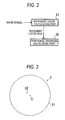
Fig. 2 is a block diagram showing schematic constitution of an analysis device shown inFig. 1 ; -
Fig. 3 is a plan view showing one form of a measurement jig; -
Fig. 4 is a plan view showing another form of the measurement jig; -
Fig. 5 is a schematic diagram showing intensity distribution of a magnified image to be picked up; -
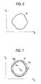
Fig. 6 is a schematic diagram showing an example of movement locus of the magnified image; and -
Fig. 7 is a schematic diagram showing outline of how to find positional variation amount of the rotation center line. - An embodiment of the invention will be described below in detail with reference to the above drawings. Each figure used in description of the embodiment does not show the detailed shape and structure of the invention, but the size of each member and distance between the members have been appropriately changed in each figure.
- An apparatus of measuring positional variation of a rotation center line shown in
Fig. 1 (which may be hereinafter referred to as an "apparatus in this embodiment") is used to measure and analyze the positional variation amount of a rotation center line A of a sample 5 (for example, a main spindle of a lathe machine) accompanied with the rotation of thesample 5, which includes amicroscope 1, ananalysis device 2 as an analysis unit, and a measurement jig 3 placed and fixed onto a leadingend surface 5a of thesample 5. The rotation center line A of thesample 5 is treated as what is fixed to thesample 5, and the leadingend surface 5a of thesample 5 is formed perpendicularly to the rotation center line A. - The
above microscope 1, as shown inFig. 1 , is composed of an epi-illuminationoptical system 10A and an observationoptical system 10B. The epi-illuminationoptical system 10A of these systems includes alight source 11, acollector lens 12, an aperture stop AS, a field stop FS, afield lens 13, ahalf mirror 14, and anobjective lens 15. The epi-illuminationoptical system 10A is constituted so as to illuminate light beam outputted from thelight source 11 onto the measurement jig 3 as illumination light. On the other hand, the observationoptical system 10B includes theobjective lens 15 used also in the epi-illuminationoptical system 10A, animaging lens 16, animaging camera 17 as an image pick-up unit. The observationoptical system 10B is constituted so as to form a magnified image of an observational object (in the apparatus in this embodiment, aposition indicator 32 described later) in an observed area of themicroscope 1, onto a two-dimensional image sensor 18 (composed of CCD, CMOS, and the like) of theimaging camera 17 by theobjective lens 15 and theimaging lens 16, and pick up this magnified image by theimaging camera 17. - The
above analysis device 2 is constituted by a computer or the like which performs image processing and various operational processing. Theanalysis device 2 includes a memory device which stores various programs, such as a hard disc, and a CPU which performs various operational processing, and also includes a movementlocus calculating part 21 constituted by the CPU and the programs in the memory, and a positional variation calculation part 22 (refer toFig. 2 ). - The above measurement jig 3, as shown in
Fig. 3 , includes abase plate 31, and aposition indicator 32 formed in the vicinity of a center point C of thebase plate 31. Thisposition indicator 32 is constituted by a metal film of gold, aluminum, chrome, or the like formed on thebase plate 31 by vapor deposition. Further, the size of thisposition indicator 32 may be appropriately set in response to observation magnification of themicroscope 1, wavelength of the illumination light, and the like. In the apparatus in this embodiment, the observation magnification of themicroscope 1 is taken as 2000 magnifications, center wavelength of the illumination light is taken as 405 nm, and the diameter of theposition indicator 32 is set to about 300 nm. Further, on the surface of thebase plate 31, an antireflection film is formed in other areas than an area where theposition indicator 32 is formed, whereby the reflection of the illumination light is suppressed. - Further, in place of the measurement jig 3, a
measurement jig 3A shown inFig. 4 may be also used. Thismeasurement jig 3A is different from the above measurement jig 3 in that threeposition indicators 32A to 32C are formed in the vicinity of the center point C' of abase plate 31A. Further, the threeposition indicators 32A to 32C are formed in positions which are different from one another in distance to the center point C'. - Next, a method of measuring the positional variation of a rotation center line according to one embodiment of the invention (hereinafter referred to as a method in this embodiment) will be described. The method in this embodiment is performed using the above-mentioned apparatus of measuring the positional variation of the rotation center line.
- (1) The
microscope 1 shown inFig. 1 is arranged so that an optical axis L of theobjective lens 15 becomes parallel to the rotation center line A of thesample 5, and so that the rotation center line A is located in the observed area of themicroscope 1. In the method in this embodiment, the position of themicroscope 1 is adjusted so that the above optical axis L and the above rotation center line A are superimposed on each other (this is not the indispensable feature of the invention). - (2) The measurement jig 3 shown in
Fig. 3 is placed and fixed onto the leadingend surface 5a of thesample 5 so that theposition indicator 32 may rotate in the above observed area integrally with the sample 5 (refer toFig. 1 ). Further, in the method in this embodiment, the position of the measurement jig 3 is adjusted so that the center point C of thebase plate 31 of the measurement jig 3 is located on the above optical axis L (this is not the indispensable feature of the invention). - (3) The
sample 5 is rotated, and the magnified image of theposition indicator 32 formed on the two-dimensional image senor 18 by theobjective lens 15 and theimaging lens 16 is picked up by theimaging camera 17 at the plural time points during the rotation of thesample 5. The number of image pick-up may be appropriately set in response to the rotary speed of thesample 5. In the method of this embodiment, the image is picked up 10000 times/min. - (4) A movement locus P (refer to
Fig. 6 ) of the magnified images picked up at the plural time points is found in an imaging coordinate system appropriately set according to the two-dimensional image sensor 18. The outline of how to find this movement locus P is as follows.- (a) First, each image data picked up is binarized, whereby the center position of the magnified image is readily specified. Though a threshold in binarization may be appropriately set in response to a relation between the size of the magnified image and pixel density of the two-
dimensional image sensor 18, high setting facilitates specifying of the center position of the magnified image. For example, in case that the magnified image is taken as a circular spot image, and the intensity distribution of its spot image becomes Gaussian distribution (shown two-dimensionally) as shown inFig. 5 , when the threshold is set to I2 where the intensity becomes 1/e (e is Napier's constant) of a maximum intensity IM, and particularly when the threshold is set to I3 where the intensity becomes 8/9 of the maximum intensity IM than when the threshold is set to I1 where the intensity becomes 1/e2 of the maximum intensity IM, the diameter of the magnified image after binarization becomes smaller (d3>d2>d1). Therefore, specifying of the center position of the magnified image is facilitated. - (b) Next, in the imaging coordinate system, a coordinate value of the center position (barycentric position may be taken) of the magnified image after the binarization is found for each of the above image data, and their coordinate values are connected in order of image pick-up, whereby the movement locus P is obtained. The calculation of this movement locus P is executed by the movement locus calculating means 21.
- (a) First, each image data picked up is binarized, whereby the center position of the magnified image is readily specified. Though a threshold in binarization may be appropriately set in response to a relation between the size of the magnified image and pixel density of the two-
- (5) On the basis of the movement locus P obtained in the above step (4), the positional variation amount δ (refer to
Fig. 7 ) of the rotation center line A of thesample 5 is calculated. The outline of how to find this positional variation amount δ is as follows.- (a) First, a least square circle So fitting to the movement locus P is found, and a center point To of the least square circle is specified.
- (b) Next, a large circle SM which is concentric with the least square circle So (has the center point T0) and circumscribes the movement locus P, and a small circle Sm which is concentric with the least square circle So (has the center point To) and inscribed in the movement locus P are found.
- (c) Next, difference of radius between the large circle SM and the small circle Sm is calculated as the positional variation amount δ. This calculation of the positional variation amount δ is executed by the position
variation calculating means 22.
- Although the embodiment of the invention has been described above, the invention is not limited the above embodiment, but the form of the invention may be changed variously.
- For example, although the measurement jig 3 shown in
Fig. 3 is used in the embodiment, themeasurement jig 3A shown inFig. 4 may be also used in place of the measurement jig 3. Although a measurement procedure in this case is similar to the procedure in case that the measurement jig 3 is used, since themeasurement jig 3A has the threeposition indicators 32A to 32C, three movement loci corresponding to therespective position indicators 32A to 32C are found. Therefore, each the positional variation amount (δ1, δ2, δ3) is found by the above procedure for each of the three movement loci, and these positional variation amounts are averaged, whereby the positional variation amount (=(δ1+δ2+δ3)/3) may be calculated. - Further, although the
position indicators optical system 10A. - Further, by using together a displacement meter (The number of displacement meters may be one. Not shown) which measures the shape of the peripheral surface of the sample, it is also possible to measure circularity of the peripheral surface of the sample.
Claims (3)
- A positional variation measuring method which measures a positional variation of a rotation center line of a sample accompanied with a rotation of the sample, which provides a microscope arranged so that an optical axis of an objective lens and the rotation center line become parallel to each other, and so that the rotation center line is located in an observed area of the microscope, and a position indicator that is set on the sample so as to be capable of rotating in the observed area integrally with the sample, and magnified with the microscope to be observed, comprising the steps of:rotating the sample to measure the positional variation of the rotation center line of the sample;picking up respectively magnified images of the position indicator formed through the objective lens at plural time points during the rotation of the sample;finding a movement locus in an imaging coordinate system of the magnified images picked up; andcalculating the position variation amount of the rotation center line on the basis of the found movement locus.
- A positional variation measuring apparatus which measures a positional variation of a rotation center line of a sample accompanied with a rotation of the sample, the apparatus comprising:a microscope arranged so that an optical axis of an objective lens and the rotation center line become parallel to each other, and so that the rotation center line is located in an observed area of the microscope;at least one position indicator which is set on the sample so as to be capable of rotating in the observed area integrally with the sample, and magnified with the microscope to be observed;an imaging unit which picks up respectively magnified images of the position indicator formed through the objective lens at plural time points during the rotation of the sample; andan analysis unit which finds a movement locus in an imaging coordinate system of the magnified images picked up, and calculates a position variation amount of the rotation center line on the basis of the found movement locus.
- The positional variation measuring apparatus according to Claim 2, wherein a plurality of position indicators are arranged in the observed area of the microscope.
Applications Claiming Priority (1)
| Application Number | Priority Date | Filing Date | Title |
|---|---|---|---|
| JP2009074467A JP2010223915A (en) | 2009-03-25 | 2009-03-25 | Method and apparatus for measuring position variation of rotation center line |
Publications (1)
| Publication Number | Publication Date |
|---|---|
| EP2233883A1 true EP2233883A1 (en) | 2010-09-29 |
Family
ID=42270070
Family Applications (1)
| Application Number | Title | Priority Date | Filing Date |
|---|---|---|---|
| EP10157602A Withdrawn EP2233883A1 (en) | 2009-03-25 | 2010-03-24 | Method and apparatus of measuring positional variation of rotation center line |
Country Status (4)
| Country | Link |
|---|---|
| US (1) | US20100246900A1 (en) |
| EP (1) | EP2233883A1 (en) |
| JP (1) | JP2010223915A (en) |
| CN (1) | CN101846496A (en) |
Families Citing this family (11)
| Publication number | Priority date | Publication date | Assignee | Title |
|---|---|---|---|---|
| JP2012093243A (en) * | 2010-10-27 | 2012-05-17 | Toyama Prefecture | Tool position measurement device |
| CN102565459A (en) * | 2011-12-29 | 2012-07-11 | 中国科学院长春光学精密机械与物理研究所 | Transparent illumination device applied to process of detecting micro-pore shape by atomic force microscope |
| EP2933601B1 (en) | 2012-12-14 | 2019-09-11 | National Institute of Advanced Industrial Science and Technology | Light source position detection apparatus, light source tracking apparatus, control method, and program |
| JP6206258B2 (en) * | 2014-03-06 | 2017-10-04 | 富士通株式会社 | Trajectory estimation device, trajectory estimation method, and program |
| JP6598807B2 (en) * | 2017-03-13 | 2019-10-30 | 株式会社Screenホールディングス | Inspection method and inspection apparatus |
| JP6671310B2 (en) * | 2017-03-13 | 2020-03-25 | 株式会社Screenホールディングス | Work holding device, inspection device, and work position correction method |
| CN107179049A (en) * | 2017-05-27 | 2017-09-19 | 中国科学院上海技术物理研究所 | The optical measuring device and method of a kind of high-precision shafting running accuracy |
| JP7078560B2 (en) * | 2019-01-25 | 2022-05-31 | ファナック株式会社 | Precision machine tools |
| CN110142518B (en) * | 2019-05-21 | 2020-11-13 | 奔腾激光(温州)有限公司 | Method for detecting precision of rotation center for laser cutting and adjusting device thereof |
| CN113819858B (en) * | 2021-11-24 | 2022-03-08 | 南京快轮智能科技有限公司 | Detection device and method for electric scooter hub |
| JP2024084309A (en) * | 2022-12-13 | 2024-06-25 | 日機装株式会社 | Information processing device, information processing program, and information processing method |
Citations (5)
| Publication number | Priority date | Publication date | Assignee | Title |
|---|---|---|---|---|
| JPS61191912A (en) * | 1985-02-20 | 1986-08-26 | Kasen Nozuru Seisakusho:Kk | Method and apparatus for measuring eccentricity |
| DE4038727A1 (en) * | 1990-12-05 | 1992-06-11 | Ilmenau Tech Hochschule | Lens adjustment arrangement for frame mounting of lenses - has mechanical adjustment system and optical system for generating and evaluating reflex images |
| EP0542251A2 (en) * | 1991-11-15 | 1993-05-19 | SIP SOCIETA ITALIANA PER l'ESERCIZIO DELLE TELECOMUNICAZIONI P.A. | Method of and apparatus for measuring the geometric characteristics of nominally cylindrical guiding structures |
| US20020174707A1 (en) * | 2001-05-28 | 2002-11-28 | Susumu Sawafuji | Work center position determining method and apparatus |
| US20030227633A1 (en) * | 2002-06-07 | 2003-12-11 | Fuji Photo Optical Co., Ltd. | Method of assisting sample inclination error adjustment |
Family Cites Families (1)
| Publication number | Priority date | Publication date | Assignee | Title |
|---|---|---|---|---|
| EP1052683A4 (en) * | 1998-01-29 | 2004-03-17 | Nikon Corp | Exposure method and device |
-
2009
- 2009-03-25 JP JP2009074467A patent/JP2010223915A/en not_active Withdrawn
-
2010
- 2010-03-22 CN CN201010150116.5A patent/CN101846496A/en active Pending
- 2010-03-24 EP EP10157602A patent/EP2233883A1/en not_active Withdrawn
- 2010-03-24 US US12/730,696 patent/US20100246900A1/en not_active Abandoned
Patent Citations (5)
| Publication number | Priority date | Publication date | Assignee | Title |
|---|---|---|---|---|
| JPS61191912A (en) * | 1985-02-20 | 1986-08-26 | Kasen Nozuru Seisakusho:Kk | Method and apparatus for measuring eccentricity |
| DE4038727A1 (en) * | 1990-12-05 | 1992-06-11 | Ilmenau Tech Hochschule | Lens adjustment arrangement for frame mounting of lenses - has mechanical adjustment system and optical system for generating and evaluating reflex images |
| EP0542251A2 (en) * | 1991-11-15 | 1993-05-19 | SIP SOCIETA ITALIANA PER l'ESERCIZIO DELLE TELECOMUNICAZIONI P.A. | Method of and apparatus for measuring the geometric characteristics of nominally cylindrical guiding structures |
| US20020174707A1 (en) * | 2001-05-28 | 2002-11-28 | Susumu Sawafuji | Work center position determining method and apparatus |
| US20030227633A1 (en) * | 2002-06-07 | 2003-12-11 | Fuji Photo Optical Co., Ltd. | Method of assisting sample inclination error adjustment |
Also Published As
| Publication number | Publication date |
|---|---|
| JP2010223915A (en) | 2010-10-07 |
| US20100246900A1 (en) | 2010-09-30 |
| CN101846496A (en) | 2010-09-29 |
Similar Documents
| Publication | Publication Date | Title |
|---|---|---|
| US20100246900A1 (en) | Method and apparatus of measuring positional variation of rotation center line | |
| Szydłowski et al. | Machine vision micro-milling tool wear inspection by image reconstruction and light reflectance | |
| TWI327639B (en) | ||
| CN107356608A (en) | The quick dark field detection method of heavy caliber fused quartz optical component surface microdefect | |
| CN109952526B (en) | System and method for dimensional calibration of analytical microscopes | |
| US9471984B2 (en) | Method for self-calibration of a microscope apparatus | |
| US11774233B2 (en) | Method and system for measuring geometric parameters of through holes | |
| KR20190112108A (en) | Camera and specimen alignment to facilitate large area imaging in microscopy | |
| TW200834473A (en) | Method for assessing image focus quality | |
| CN106247961A (en) | The precision measurement system of a kind of bore inner diameter and method | |
| EP2002204B1 (en) | Method and apparatus for determining and gauging deviations in shape and waviness of rotationally symmetrical parts | |
| EP2138803A1 (en) | Jig for measuring an object shape and method for measuring a three-dimensional shape | |
| EP1903300B1 (en) | Shape measurement method and shape measurement apparatus | |
| CN115127483A (en) | Detection method for measuring coaxiality and system for detecting coaxiality | |
| Yin et al. | Automated alignment technology for laser repair of surface micro-damages on large-aperture optics based on machine vision and rangefinder ranging | |
| CN116879166B (en) | Mechanical arm-based large-caliber plane optical element surface defect scanning method | |
| CN116878378B (en) | A method for centering and localizing large-aperture spherical optical elements under the control of a robotic arm | |
| JPH09192986A (en) | Automatic recognition method of tool edge position by image processing | |
| JP2007017276A (en) | Cutting edge inspection method and inspection apparatus | |
| De Chiffre et al. | Metrological limitations of optical probing techniques for dimensional measurements | |
| CN117606369B (en) | A sample thickness monitoring system and device | |
| JP2008058133A (en) | Measuring device for radius of curvature of long tool edge and measuring method of radius of curvature of long tool edge | |
| JPH0634552A (en) | Method and apparatus for automatic measurement of depth of local corrosion | |
| JP2005083981A (en) | Aspheric surface eccentricity measuring apparatus and method | |
| JP2006300935A (en) | Method of determining side bias of xyz stage |
Legal Events
| Date | Code | Title | Description |
|---|---|---|---|
| PUAI | Public reference made under article 153(3) epc to a published international application that has entered the european phase |
Free format text: ORIGINAL CODE: 0009012 |
|
| 17P | Request for examination filed |
Effective date: 20100324 |
|
| AK | Designated contracting states |
Kind code of ref document: A1 Designated state(s): AT BE BG CH CY CZ DE DK EE ES FI FR GB GR HR HU IE IS IT LI LT LU LV MC MK MT NL NO PL PT RO SE SI SK SM TR |
|
| AX | Request for extension of the european patent |
Extension state: AL BA ME RS |
|
| 17Q | First examination report despatched |
Effective date: 20110608 |
|
| RAP1 | Party data changed (applicant data changed or rights of an application transferred) |
Owner name: FUJIFILM CORPORATION |
|
| GRAP | Despatch of communication of intention to grant a patent |
Free format text: ORIGINAL CODE: EPIDOSNIGR1 |
|
| RIC1 | Information provided on ipc code assigned before grant |
Ipc: B23Q 17/24 20060101ALI20111130BHEP Ipc: G01B 11/27 20060101AFI20111130BHEP |
|
| STAA | Information on the status of an ep patent application or granted ep patent |
Free format text: STATUS: THE APPLICATION IS DEEMED TO BE WITHDRAWN |
|
| 18D | Application deemed to be withdrawn |
Effective date: 20120503 |