EP2233856A1 - Hot-water supply apparatus - Google Patents
Hot-water supply apparatus Download PDFInfo
- Publication number
- EP2233856A1 EP2233856A1 EP08859186A EP08859186A EP2233856A1 EP 2233856 A1 EP2233856 A1 EP 2233856A1 EP 08859186 A EP08859186 A EP 08859186A EP 08859186 A EP08859186 A EP 08859186A EP 2233856 A1 EP2233856 A1 EP 2233856A1
- Authority
- EP
- European Patent Office
- Prior art keywords
- unit
- heating
- hot water
- heat pump
- tank unit
- Prior art date
- Legal status (The legal status is an assumption and is not a legal conclusion. Google has not performed a legal analysis and makes no representation as to the accuracy of the status listed.)
- Withdrawn
Links
- XLYOFNOQVPJJNP-UHFFFAOYSA-N water Substances O XLYOFNOQVPJJNP-UHFFFAOYSA-N 0.000 title claims abstract description 146
- 238000010438 heat treatment Methods 0.000 claims abstract description 91
- 239000008236 heating water Substances 0.000 claims description 8
- 238000005259 measurement Methods 0.000 claims description 6
- 230000007812 deficiency Effects 0.000 abstract description 4
- 238000000034 method Methods 0.000 description 14
- 238000003303 reheating Methods 0.000 description 13
- 238000004891 communication Methods 0.000 description 11
- 239000003507 refrigerant Substances 0.000 description 9
- 229910001220 stainless steel Inorganic materials 0.000 description 5
- 239000010935 stainless steel Substances 0.000 description 5
- RYGMFSIKBFXOCR-UHFFFAOYSA-N Copper Chemical compound [Cu] RYGMFSIKBFXOCR-UHFFFAOYSA-N 0.000 description 4
- 229910052802 copper Inorganic materials 0.000 description 4
- 239000010949 copper Substances 0.000 description 4
- CURLTUGMZLYLDI-UHFFFAOYSA-N Carbon dioxide Chemical compound O=C=O CURLTUGMZLYLDI-UHFFFAOYSA-N 0.000 description 2
- 239000004698 Polyethylene Substances 0.000 description 2
- 230000015556 catabolic process Effects 0.000 description 2
- 239000011810 insulating material Substances 0.000 description 2
- -1 polyethylene Polymers 0.000 description 2
- 229920000573 polyethylene Polymers 0.000 description 2
- JOYRKODLDBILNP-UHFFFAOYSA-N Ethyl urethane Chemical compound CCOC(N)=O JOYRKODLDBILNP-UHFFFAOYSA-N 0.000 description 1
- 229920002430 Fibre-reinforced plastic Polymers 0.000 description 1
- 238000003287 bathing Methods 0.000 description 1
- 229910002092 carbon dioxide Inorganic materials 0.000 description 1
- 239000001569 carbon dioxide Substances 0.000 description 1
- 238000010276 construction Methods 0.000 description 1
- 238000004851 dishwashing Methods 0.000 description 1
- 230000000694 effects Effects 0.000 description 1
- 239000011151 fibre-reinforced plastic Substances 0.000 description 1
- 239000011491 glass wool Substances 0.000 description 1
- JEGUKCSWCFPDGT-UHFFFAOYSA-N h2o hydrate Chemical compound O.O JEGUKCSWCFPDGT-UHFFFAOYSA-N 0.000 description 1
- 238000012986 modification Methods 0.000 description 1
- 230000004048 modification Effects 0.000 description 1
- 230000005855 radiation Effects 0.000 description 1
- 230000004044 response Effects 0.000 description 1
- 239000008400 supply water Substances 0.000 description 1
Images


Classifications
-
- F—MECHANICAL ENGINEERING; LIGHTING; HEATING; WEAPONS; BLASTING
- F24—HEATING; RANGES; VENTILATING
- F24D—DOMESTIC- OR SPACE-HEATING SYSTEMS, e.g. CENTRAL HEATING SYSTEMS; DOMESTIC HOT-WATER SUPPLY SYSTEMS; ELEMENTS OR COMPONENTS THEREFOR
- F24D19/00—Details
- F24D19/10—Arrangement or mounting of control or safety devices
- F24D19/1006—Arrangement or mounting of control or safety devices for water heating systems
- F24D19/1051—Arrangement or mounting of control or safety devices for water heating systems for domestic hot water
- F24D19/1054—Arrangement or mounting of control or safety devices for water heating systems for domestic hot water the system uses a heat pump
-
- F—MECHANICAL ENGINEERING; LIGHTING; HEATING; WEAPONS; BLASTING
- F24—HEATING; RANGES; VENTILATING
- F24D—DOMESTIC- OR SPACE-HEATING SYSTEMS, e.g. CENTRAL HEATING SYSTEMS; DOMESTIC HOT-WATER SUPPLY SYSTEMS; ELEMENTS OR COMPONENTS THEREFOR
- F24D17/00—Domestic hot-water supply systems
- F24D17/02—Domestic hot-water supply systems using heat pumps
-
- F—MECHANICAL ENGINEERING; LIGHTING; HEATING; WEAPONS; BLASTING
- F24—HEATING; RANGES; VENTILATING
- F24H—FLUID HEATERS, e.g. WATER OR AIR HEATERS, HAVING HEAT-GENERATING MEANS, e.g. HEAT PUMPS, IN GENERAL
- F24H15/00—Control of fluid heaters
- F24H15/20—Control of fluid heaters characterised by control inputs
- F24H15/212—Temperature of the water
- F24H15/219—Temperature of the water after heating
-
- F—MECHANICAL ENGINEERING; LIGHTING; HEATING; WEAPONS; BLASTING
- F24—HEATING; RANGES; VENTILATING
- F24H—FLUID HEATERS, e.g. WATER OR AIR HEATERS, HAVING HEAT-GENERATING MEANS, e.g. HEAT PUMPS, IN GENERAL
- F24H15/00—Control of fluid heaters
- F24H15/20—Control of fluid heaters characterised by control inputs
- F24H15/227—Temperature of the refrigerant in heat pump cycles
- F24H15/232—Temperature of the refrigerant in heat pump cycles at the condenser
-
- F—MECHANICAL ENGINEERING; LIGHTING; HEATING; WEAPONS; BLASTING
- F24—HEATING; RANGES; VENTILATING
- F24H—FLUID HEATERS, e.g. WATER OR AIR HEATERS, HAVING HEAT-GENERATING MEANS, e.g. HEAT PUMPS, IN GENERAL
- F24H15/00—Control of fluid heaters
- F24H15/30—Control of fluid heaters characterised by control outputs; characterised by the components to be controlled
- F24H15/375—Control of heat pumps
- F24H15/38—Control of compressors of heat pumps
-
- F—MECHANICAL ENGINEERING; LIGHTING; HEATING; WEAPONS; BLASTING
- F24—HEATING; RANGES; VENTILATING
- F24H—FLUID HEATERS, e.g. WATER OR AIR HEATERS, HAVING HEAT-GENERATING MEANS, e.g. HEAT PUMPS, IN GENERAL
- F24H15/00—Control of fluid heaters
- F24H15/30—Control of fluid heaters characterised by control outputs; characterised by the components to be controlled
- F24H15/395—Information to users, e.g. alarms
-
- F—MECHANICAL ENGINEERING; LIGHTING; HEATING; WEAPONS; BLASTING
- F24—HEATING; RANGES; VENTILATING
- F24H—FLUID HEATERS, e.g. WATER OR AIR HEATERS, HAVING HEAT-GENERATING MEANS, e.g. HEAT PUMPS, IN GENERAL
- F24H15/00—Control of fluid heaters
- F24H15/40—Control of fluid heaters characterised by the type of controllers
- F24H15/414—Control of fluid heaters characterised by the type of controllers using electronic processing, e.g. computer-based
- F24H15/443—Control of fluid heaters characterised by the type of controllers using electronic processing, e.g. computer-based using a central controller connected to several sub-controllers
Definitions
- this kind of hot water supply apparatus having a heating unit for heating water and a tank unit for storing heated water heated by the heating unit (see the patent document 1).
- the heating unit and the tank unit can be operated only when they used as a combination of which the type of the heating unit matches with the type of the tank unit. Also, it was impossible to exchange the heating unit or the tank unit with the other type of heating unit or tank unit. On the other hand, there is an idea of enabling to connect a heating unit with a tank unit of a type that is not corresponding to the type of the heating unit. However, since the heating capabilities of heating units are different from each other, if the heating unit is connected to a tank unit and the heating unit does not have a corresponding heating capability for the tank unit, it might become impossible to supply water of required amount and temperature.
- An object of the present invention is to provide a hot water supply apparatus capable of determining whether a heating unit has a heating capability capable of corresponding to a tank unit when one of heating unit or tank unit is exchanged.
- a hot water supply apparatus comprises a heating unit for heating water, a tank unit for storing hot water heated by the heating unit, a memory for memorizing a plurality of type data of heating units each of which has heating capability corresponding to the tank unit, and a determining portion for determining whether the heating unit which is connected to the tank unit has a heating capability capable of corresponding to the tank unit based on the type data of heating units memorized in the memory.
- the heating unit which is connected to the tank unit is a type having a heating capability capable of corresponding to the tank unit. Therefore, supplying to users, together with a tank unit, a heating unit which does not have a heating capability capable of corresponding to the tank unit may be prevented.
- a hot water supply apparatus comprises a heating unit for heating water, a tank unit for storing hot water heated by the heating unit, a capability measurement portion for measuring a heating capability of the heating unit by operating the heating unit connected to the tank unit, and a determining portion which regards the heating unit which is connected to the tank unit as a heating unit which has heating capability capable of corresponding to the tank unit when the measured heating capability of the heating unit measured by the capability measurement portion is equal to or more than a predetermined level.
- the heating unit which is connected to the tank unit has a heating capability capable of corresponding to the tank unit. Therefore, supplying to users, together with a tank unit, a heating unit which does not have a heating capability capable of corresponding to the tank unit may be prevented.
- 10 heat pump unit, 20 ... tank unit, 70 ... controller, 71 ... remote controller for kitchen, 71b... display portion, 72 ... remote controller for bathroom, 72b ... display portion, 80 ... heat pump controller.
- FIGS. 1 and 2 show a first embodiment of the present invention.
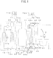
- FIG.1 is a schematic configuration view of a hot water supply apparatus
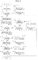
- FIG. 2 is a flow chart showing an operation of a controller when connecting a heat pump unit to a tank unit.
- This hot water supply apparatus comprises a heat pump unit 10 for heating water by using electric power, a tank unit 20 for storing hot water heated by the heat pump unit 10, a water supply pipe 30 for supplying water to the tank unit 20, a bathroom, and a kitchen, a hot water supply pipe 40 for supplying hot water stored in the tank unit 20 to the bathroom and the kitchen, a first circulation circuit 50 for circulating water between heat pump unit 10 and tank unit 20, and a second circulation circuit 60 for circulating water in a bathtub 61 between the tank unit 20 and a bathtub 61 in the bathroom.
- This hot water supply apparatus is to store in the tank unit 20 hot water heated by the heat pump unit 10 and to supply hot water stored in the tank unit 20 for washing dishes in the kitchen, for bathing in the bathroom, and etc., and also to supply hot water stored in the tank unit 20 as a heat source for reheating stored hot water in the bathtub 61.
- the heat pump unit 10 comprises an electrically-powered compressor 11, a gas cooler 12, an expansion valve 13, and an evaporator 14, which are connected in series by pipes made by copper or stainless steel so as to configure a refrigerant circuit 10a. Also, the refrigerant circuit 10a is filled with carbon dioxide as a refrigerant of which high-pressure side becomes in a supercritical state.
- the gas cooler 12 is a refrigerant-water heat exchanger in which a flow passage on a water side form a part of the first circulation circuit 50.
- the evaporator 14 is a refrigerant-air heat exchanger, and a fan 14a is provided in the vicinity of the evaporator 14 so that air which exchanges heat with the refrigerant in the evaporator 14 can flow through the evaporator.
- the tank unit 20 comprises a hot water storage tank 21, a reheating heat exchanger 22 for conducting heat exchange between water in the bath tub 61, which flows through the second circulation circuit 60, and hot water in the hot water storage tank 21, and a third circulation circuit 23 for circulating hot water between the hot water storage tank 21 and the reheating heat exchanger 22.
- the hot water storage tank 21 is made of stainless steel or fiber reinforced plastic (FRB), etc., and is covered with a heat insulating material such as glass-wool, foamed urethane, vacuumed heat insulating material, or etc. so as to prevent heat radiation of a stored hot water. Also, in this embodiment, as the hot water storage tank 21, a 370 liter tank is used.
- the reheating heat exchanger 22 is a water-water heat exchanger, and one side of flow passages of the reheating heat exchanger 22 forms a part of the second circulation circuit 60, and the other side of the flow passages of the reheating heat exchanger 22 forms a part of the third circulation circuit 23.
- the third circulation circuit 23 is configured by connecting in series an upper part of the hot water storage tank 21, the reheating heat exchanger 22, a circulation pump 23a, and a lower part of the hot water storage tank 21 by copper pipes or stainless steel pipes. Hot water in the upper part of the hot water storage tank 21 returns to the lower part of the hot water storage tank 21 via the reheating heat exchanger 22 by the circulation pump 23a.
- the water supply pipe 30 comprises a first water supply pipe 31 connected to the lower part of the hot water storage tank 21, a second water supply pipe 32 connected to the hot water supply pipe 40, and a third water supply pipe 33 connected to faucets A in the bathroom and the kitchen.
- a pressure reducing valve 30a is provided on the water supply pipe 30 which is located at an upper stream side relative to the first water supply pipe 31, the second water supply pipe 32, and the third water supply pipe 33 so as to reduce pressure of water supplied from waterworks to make the water pressure be at a predetermined pressure and make the water flow.
- the hot water supply pipe 40 comprises a first hot water supply pipe 41, one side of which is connected to the upper part of the hot water storage tank 21 and the other side of which is connected to a first mixing valve 40a, which is for mixing hot water in the hot water storage tank 21 with water which flows through the second water supply pipe 32, and a second mixing valve 40b, a second hot water supply pipe 42, one side of which is connected to the first mixing valve 40a and the other side of which is connected to the faucet A in the bathroom and the kitchen, and a third hot water supply pipe 43, one side of which is connected to the second mixing valve 40b and the other side of which is connected to the second circulation circuit 60.
- Hot water in the upper part of the hot water storage tank 21 flows through the hot water supply pipe 40 in accordance with pressure of water flows into the hot water storage tank 21 from the first water supply pipe 31. Also, on the third hot water supply pipe 43, a solenoid valve 43a for opening and closing the flow passage of the third hot water supply pipe 43 is provided.
- the first circulation circuit 50 is configured by connecting in series the lower part of the hot water storage tank 21, a circulation pump 51, the gas cooler 12, and the upper part of the hot water storage tank 21 by copper pipes, stainless steel pipes, vulcanized polyethylene pipes, or etc., and water in the lower part of the hot water storage tank 21 flows into the upper part of the hot water storage tank 21 via the gas cooler 12 by the circulation pump 51.
- the second circulation circuit 60 is configured by connecting in series the bathtub 61, the circulation pump 62, the reheating heat exchanger 22, and the bathtub 61 by copper pipes, stainless steel pipes, vulcanized polyethylene pipes, or etc., and hot water in the bathtub 61 returns to the bathtub 61 via the reheating heat exchanger 22 by the circulation pump 62.
- the hot water supply apparatus comprises a main controller 70 provided on the tank unit 20 for controlling operations, a heat pump controller 80 which receives signals from the main controller 70 and controls operations of the heat pump unit 10, the heat pump controller 80 provided in the heat pump unit 10, a remote controller for kitchen 71, and a remote controller for bathroom 72 provided respectively in the kitchen and the bathroom so as to control and set up the operations.
- the controller 70 is composed by a microcomputer, a memory of the microcomputer memorizes programs for operations, operation modes, and etc., and information such as type data of heat pump unit 10 capable of corresponding to the tank unit 20, and etc. Also, the main controller 70 is capable of communicating with the heat pump controller 80 by a first communication method or a second communication method which are different with each other, and there are differences such as difference relating amounts of data capable of being transmitted.
- the heat pump controller 80 is connected to the main controller 70 by a communication cable, receives signals transmitted from the main controller 70, and controls operations of equipments such as the compressor 11 and the fan 14a of the heat pump unit 10, and etc. Also, the heat pump controller 80 sends a type data of the heat pump unit 10 in response to operation status of the heat pump unit 10 and the signals transmitted from the main controller 70.
- a remote controller for kitchen 71 and a remote controller for bathroom 72 are connected to the main controller 70 by communication cables respectively, and the remote controller for kitchen 71 and the remote controller for bathroom 72 each comprises a plurality of switches 71a and 72a such as switches for operations like supplying hot water to the bathtub 61, reheating water, and etc., a switch for setting temperature which is used to set up temperature of hot water to be supplied, a priority switch for changing a priority between the remote controller for kitchen 71 and the remote controller for bathroom 72, a communication switch for having conversation between a person in the kitchen and a person in the bathroom, and etc., and display portions 71b and 72b for displaying a operation status, set-up temperature, and etc.
- switches 71a and 72a such as switches for operations like supplying hot water to the bathtub 61, reheating water, and etc.
- a switch for setting temperature which is used to set up temperature of hot water to be supplied
- a priority switch for changing a priority between the remote controller for kitchen 71 and the remote controller
- the compressor 11, the fan 14a, and the circulation pump 51 are operated so as to conduct the heating-up operation for heating water by using midnight electric power and the adding water and heating operation for adding water and heating the added water when the amount of remaining hot water in the hot water storage tank 21 becomes less than a predetermined amount.
- a refrigerant discharged from the compressor 11 absorbs heat by flowing into the evaporator 14 via the expansion valve 13 after radiating heat by passing through the gas cooler 12, and the refrigerant is suck up by the compressor 11.
- water in the lower part of the hot water storage tank 21 passes through the first circulation circuit 50 by the circulation pump 51, the water is heated in the gas cooler 12 by exchanging heat with the refrigerant, and is stored in the upper part of the hot water storage tank 21.
- the operations of the compressor 11, the fan 14a, and the circulation pump 51 are stopped.
- temperature of hot water stored in the hot water storage tank 21 is set up to be within 65 ⁇ 90°C, and the amount of hot water to be stored in the hot water storage tank 21 is set up to be within 370 ⁇ 320 liters. Also, as to the adding water and heating operation, temperature of hot water stored in the hot water storage tank 21 is set up to be a set-up temperature of an immediately preceding heating-up operation.
- hot water in the upper part of the hot water storage tank 21 passes through the first hot water supply pipe 41, then, by the first mixing valve 40a, the hot water is mixed with water which passes through the second water supply pipe 32 and temperature of the mixed hot water becomes the set-up temperature set up by the remote controller for kitchen 71 or the remote controller for bathroom 72, the hot water flows through the second hot water supply pipe 42, and the hot water is supplied from the faucet A in the kitchen or in the bathroom.
- hot water in the upper part of the hot water storage tank 21 passes through the first hot water supply pipe 41, then, by the second mixing valve 40b, the hot water is mixed with water passes through the second water supply pipe 32 and temperature of the mixed hot water becomes the set-up temperature set up by the remote controller for kitchen 71 or the remoter controller for bathroom 72, the hot water flows through the third hot water supply pipe 43 and the second circulation circuit 60, and the hot water is supplied to the bathtub 61 when the bathtub 61 is to be filled with hot water.
- hot water in the bathtub 61 is circulated by the second circulation circuit 60, and hot water in the hot water storage tank 21 is circulated in the third circulation circuit 23.
- hot water in the bathtub 61 is heated at the reheating heat exchanger 21 by exchanging heat with hot water in the upper part of the hot water storage tank 21 and flows back to the bathtub 61.
- Step S1 if an initialization procedure is conducted (Step S1), and the initialization procedure is completed without problems (Step S2), the main controller 70 establishes connection with the heat pump unit 10 (Step S3), and requires the heat pump controller 80 to transmit the type data of the heat pump unit 10 via the first communication method (Step S4).
- Step S2 if the initialization procedure is failed (Step S2), an alert is displayed on the display portions 71b and 72b as being that the tank unit 20 has a problem (Step S5), and operations are stopped (Step S6).
- Step S7 When the controller70 receives the signal of type data transmitted from the heat pump controller 80 (Step S7), if the type data of the heat pump unit 10 obtained from the received signal is determined to be capable of corresponding to the tank unit 20 (Step S8), a control constant or etc. which corresponds to the type of the heat pump unit 10 is set up (Step S9). Also, if the type data of the heat pump unit 10 obtained from the received signal is determined to be incapable of corresponding to the tank unit 20 (Step S8), an alert alerting that the type of the heat pump unit 10 is not suitable for the tank unit 20 is displayed (Step S10), and the operations are stopped (Step S11).
- Step S7 the heat pump controller 80 is requested to transmit the type data of the heat pump unit 10 by the second communication method (Step S12).
- Step S13 communication method is set up to be the second communication method (Step S14)
- Step S15 an alert alerting that the communication method is not applicable is displayed (Step S15), and operations are stopped (Step S16).
- Step S17 when the type data of the heat pump unit 10 obtained from the received signal is determined to be capable of corresponding to the tank unit 20 (Step S17), a control constant or etc. which corresponds to the type of the heat pump unit 10 is set up (Step S18). Also, when the type of the heat pump unit 10 obtained from the received signal is determined to be incapable of corresponding to the tank unit 20 (Step S17), an alert alerting that the type of the heat pump unit 10 is not applicable for the tank unit 20 is displayed (Step S19), and the operations are stopped (Step S20).
- the hot water supply apparatus of this embodiment it is determined whether the heat pump unit 10 which is connected to the tank unit 20 has a heating capability capable of corresponding to the tank unit 20 based on the type data of the heat pump units 10 each having a corresponding heating capability to the tank unit 20 memorized by the main controller 70.
- the main controller 70 it becomes possible to prevent supplying to users, together with a tank unit 20, a heat pump unit 10 which does not have a heating capability capable of corresponding to the tank unit 20. Therefore, it is possible to prevent causing inconveniences after the supplying caused by the deficiency of the heating capability.
- FIGS. 3 and 4 show the second embodiment of the present invention.
- FIG. 3 is a schematic configuration view of the hot water supply apparatus
- FIG. 4 is a flow chart showing an operation of the controller when connecting a heat pump unit to the tank unit. Also, the elements which are the same to the ones in the previously explained first embodiment are assigned the same symbols.
- the heat pump controller 80 of this hot water supply apparatus is connected with the compressor 11, a first temperature detector 81 for detecting temperature of hot water flows from the gas cooler 12 of the first circulation circuit 50, and a second temperature detector 82 for detecting temperature of refrigerant discharged from the compressor 11 of the refrigerant circuit 10a, and the heat pump controller 80 transmits signals of the compressor 11, the first temperature detector 81, and the second temperature detector 82 to the main controller 70.
- Step S31 if an initialization procedure is conducted (Step S31), and the initialization procedure is completed without problems (Step S32), the main controller 701 establishes connection with the heat pump unit 10 (Step S33), and requires the heat pump unit 10 to start operation (Step S34). At this time, if the initialization procedure is failed (Step S32), the alert is displayed on the display portions 71b and 72b as being that the tank unit 20 has a problem (Step S35), and the operations are stopped (Step S36).
- Step S37 when operation of the compressor 11 is confirmed (Step S37), and a detected temperature T1 of the first temperature detector 81 is higher than a predetermined temperature T1s (Step S38), and a detected temperature T2 of the second temperature detector 82 is higher than a predetermined temperature T2s (Step S39), a heating capability of the heat pump unit 10 is calculated based on the detected temperature T1 of the temperature detector 81 and the detected temperature T2 of the temperature detector 82 (Step S40), a result that the connected heat pump unit 10 is capable of corresponding to the heat pump unit 20, and the calculated heating capability are displayed on the display portions 71b and 72b (Step S41), and the operations of the heat pump unit 10 is stopped (Step S42).
- Step S37 if the operation of the compressor 11 can not be confirmed (Step S37), if the detected temperature T1 of the first temperature detector 81 is lower than the predetermined temperature T1s (Step S38), or if the detected temperature T2 of the second temperature detector 82 is lower than the predetermined temperature T2s (Step S39), the alert alerting that the connected heat pump unit 10 does not correspond to the tank unit 20 is displayed (Step S43), and the operations of the heat pump unit 10 are stopped (Step S44).
- an operation mode corresponds to a maximum capability of the heat pump unit 10 (for example, water temperature: 80°C, amount of hot water: 370 liters, and etc.) is calculated and displayed on the display portions 71b and 72b.
- the heating capability of the heat pump unit 10 is measured by operating the heat pump unit 10 which is connected to the tank unit 20. And when the measured heating capability is higher than a predetermined value, the heat pump unit 10 connected to the tank unit 20 is determined to be capable of corresponding to the tank unit 20.
- the heat pump unit 10 which does not have the heating capability capable of corresponding to the tank unit 20. Therefore, it is possible to prevent causing inconveniences after the supplying caused by the deficiency of the heating capability.
- the alert is displayed on the display portions 71b and 72b.
- the heat pump unit 10 connected to the tank unit 20 does not have the sufficient heating capability capable of corresponding to the tank unit 20. Therefore, it is possible to surely prevent a construction error.
- the operation mode which corresponding to the maximum capability of the connected heat pump unit 10 is displayed on the display portions 71b and 72b or etc. By this, it becomes possible for users to know the heating capability of the heat pump unit 10 easily. Therefore, it becomes capable of replacing the heat pump unit 10 according to judgment of users.
- the embodiments only disclosed the hot water supply apparatus which comprises the heat pump unit 10 and the tank unit 20 separately, however, the invention can be applied to a hot water supply apparatus integrally comprises the heat pump unit 10 and the tank unit 20.
Landscapes
- Engineering & Computer Science (AREA)
- Physics & Mathematics (AREA)
- Thermal Sciences (AREA)
- Chemical & Material Sciences (AREA)
- Combustion & Propulsion (AREA)
- Mechanical Engineering (AREA)
- General Engineering & Computer Science (AREA)
- Computer Hardware Design (AREA)
- Heat-Pump Type And Storage Water Heaters (AREA)
Abstract
An object of the present invention is to provide a hot water supply apparatus capable of determining whether a heating unit has a heating capability capable of corresponding to a tank unit when one of the heating unit or the tank unit is replaced. Whether a heat pump unit 10 which is connected to a tank unit 20 has a heating capability capable of corresponding to the tank unit 20 is determined based on type data of the heat pump unit 10 having a heating capability capable of corresponding to the tank unit 20 memorized by a main controller 70. By this, it becomes possible to prevent supplying to users, together with the tank unit 20, the heat pump unit 10 which does not have the heating capability capable of corresponding to the tank unit 20. Therefore, it is possible to prevent causing inconveniences after the supplying caused by the deficiency of the heating capability.
Description
- The present invention relates to a hot water supply apparatus comprises a heating unit for heating water and a tank unit for storing heated water heated by the heating unit.
- Conventionally, this kind of hot water supply apparatus having a heating unit for heating water and a tank unit for storing heated water heated by the heating unit (see the patent document 1).
- Patent Document 1: Japanese Patent publication No.
2007-240151 - In the said conventional hot water supply apparatus, the heating unit and the tank unit can be operated only when they used as a combination of which the type of the heating unit matches with the type of the tank unit. Also, it was impossible to exchange the heating unit or the tank unit with the other type of heating unit or tank unit. On the other hand, there is an idea of enabling to connect a heating unit with a tank unit of a type that is not corresponding to the type of the heating unit. However, since the heating capabilities of heating units are different from each other, if the heating unit is connected to a tank unit and the heating unit does not have a corresponding heating capability for the tank unit, it might become impossible to supply water of required amount and temperature.
- An object of the present invention is to provide a hot water supply apparatus capable of determining whether a heating unit has a heating capability capable of corresponding to a tank unit when one of heating unit or tank unit is exchanged.
- To achieve the above object, in the present invention, a hot water supply apparatus comprises a heating unit for heating water, a tank unit for storing hot water heated by the heating unit, a memory for memorizing a plurality of type data of heating units each of which has heating capability corresponding to the tank unit, and a determining portion for determining whether the heating unit which is connected to the tank unit has a heating capability capable of corresponding to the tank unit based on the type data of heating units memorized in the memory.
- By this, it is determined whether the heating unit which is connected to the tank unit is a type having a heating capability capable of corresponding to the tank unit. Therefore, supplying to users, together with a tank unit, a heating unit which does not have a heating capability capable of corresponding to the tank unit may be prevented.
- Also, to achieve the above object, in the present invention, a hot water supply apparatus comprises a heating unit for heating water, a tank unit for storing hot water heated by the heating unit, a capability measurement portion for measuring a heating capability of the heating unit by operating the heating unit connected to the tank unit, and a determining portion which regards the heating unit which is connected to the tank unit as a heating unit which has heating capability capable of corresponding to the tank unit when the measured heating capability of the heating unit measured by the capability measurement portion is equal to or more than a predetermined level.
- By this, it is determined whether the heating unit which is connected to the tank unit has a heating capability capable of corresponding to the tank unit. Therefore, supplying to users, together with a tank unit, a heating unit which does not have a heating capability capable of corresponding to the tank unit may be prevented.
- According to this invention, it is possible to prevent supplying to users, together with a tank unit, a heating unit which does not have a heating capability capable of corresponding to the tank unit. Therefore, it is possible to prevent causing inconveniences after the supplying caused by the deficiency of the heating capability.
- The above and other objects, features, and advantages of the present invention will become more apparent from the following description and the accompanying drawings.
-
-
FIG. 1 is a schematic configuration view of a hot water supply apparatus showing a first embodiment of the present invention; -
FIG. 2 is a flow chart showing an operation of a controller when connecting a heat pump unit to a tank unit; -
FIG. 3 is a schematic configuration view of the hot water supply apparatus showing a second embodiment of the present invention; -
FIG. 4 is a flow chart showing an operation of the controller when connecting the heat pump unit to the tank unit. - 10 ... heat pump unit, 20 ... tank unit, 70 ... controller, 71 ... remote controller for kitchen, 71b... display portion, 72 ... remote controller for bathroom, 72b ... display portion, 80 ... heat pump controller.
-
FIGS. 1 and2 show a first embodiment of the present invention.FIG.1 is a schematic configuration view of a hot water supply apparatus, andFIG. 2 is a flow chart showing an operation of a controller when connecting a heat pump unit to a tank unit. - This hot water supply apparatus comprises a
heat pump unit 10 for heating water by using electric power, atank unit 20 for storing hot water heated by theheat pump unit 10, awater supply pipe 30 for supplying water to thetank unit 20, a bathroom, and a kitchen, a hotwater supply pipe 40 for supplying hot water stored in thetank unit 20 to the bathroom and the kitchen, afirst circulation circuit 50 for circulating water betweenheat pump unit 10 andtank unit 20, and asecond circulation circuit 60 for circulating water in abathtub 61 between thetank unit 20 and abathtub 61 in the bathroom. This hot water supply apparatus is to store in thetank unit 20 hot water heated by theheat pump unit 10 and to supply hot water stored in thetank unit 20 for washing dishes in the kitchen, for bathing in the bathroom, and etc., and also to supply hot water stored in thetank unit 20 as a heat source for reheating stored hot water in thebathtub 61. - The
heat pump unit 10 comprises an electrically-powered compressor 11, agas cooler 12, anexpansion valve 13, and anevaporator 14, which are connected in series by pipes made by copper or stainless steel so as to configure a refrigerant circuit 10a. Also, the refrigerant circuit 10a is filled with carbon dioxide as a refrigerant of which high-pressure side becomes in a supercritical state. Thegas cooler 12 is a refrigerant-water heat exchanger in which a flow passage on a water side form a part of thefirst circulation circuit 50. Theevaporator 14 is a refrigerant-air heat exchanger, and a fan 14a is provided in the vicinity of theevaporator 14 so that air which exchanges heat with the refrigerant in theevaporator 14 can flow through the evaporator. - The
tank unit 20 comprises a hotwater storage tank 21, areheating heat exchanger 22 for conducting heat exchange between water in thebath tub 61, which flows through thesecond circulation circuit 60, and hot water in the hotwater storage tank 21, and athird circulation circuit 23 for circulating hot water between the hotwater storage tank 21 and thereheating heat exchanger 22. - The hot
water storage tank 21 is made of stainless steel or fiber reinforced plastic (FRB), etc., and is covered with a heat insulating material such as glass-wool, foamed urethane, vacuumed heat insulating material, or etc. so as to prevent heat radiation of a stored hot water. Also, in this embodiment, as the hotwater storage tank 21, a 370 liter tank is used. - The
reheating heat exchanger 22 is a water-water heat exchanger, and one side of flow passages of the reheatingheat exchanger 22 forms a part of thesecond circulation circuit 60, and the other side of the flow passages of the reheatingheat exchanger 22 forms a part of thethird circulation circuit 23. - The
third circulation circuit 23 is configured by connecting in series an upper part of the hotwater storage tank 21, thereheating heat exchanger 22, a circulation pump 23a, and a lower part of the hotwater storage tank 21 by copper pipes or stainless steel pipes. Hot water in the upper part of the hotwater storage tank 21 returns to the lower part of the hotwater storage tank 21 via thereheating heat exchanger 22 by the circulation pump 23a. - The
water supply pipe 30 comprises a firstwater supply pipe 31 connected to the lower part of the hotwater storage tank 21, a secondwater supply pipe 32 connected to the hotwater supply pipe 40, and a thirdwater supply pipe 33 connected to faucets A in the bathroom and the kitchen. A pressure reducing valve 30a is provided on thewater supply pipe 30 which is located at an upper stream side relative to the firstwater supply pipe 31, the secondwater supply pipe 32, and the thirdwater supply pipe 33 so as to reduce pressure of water supplied from waterworks to make the water pressure be at a predetermined pressure and make the water flow. - The hot
water supply pipe 40 comprises a first hot water supply pipe 41, one side of which is connected to the upper part of the hotwater storage tank 21 and the other side of which is connected to a first mixing valve 40a, which is for mixing hot water in the hotwater storage tank 21 with water which flows through the secondwater supply pipe 32, and a second mixing valve 40b, a second hotwater supply pipe 42, one side of which is connected to the first mixing valve 40a and the other side of which is connected to the faucet A in the bathroom and the kitchen, and a third hotwater supply pipe 43, one side of which is connected to the second mixing valve 40b and the other side of which is connected to thesecond circulation circuit 60. Hot water in the upper part of the hotwater storage tank 21 flows through the hotwater supply pipe 40 in accordance with pressure of water flows into the hotwater storage tank 21 from the firstwater supply pipe 31. Also, on the third hotwater supply pipe 43, a solenoid valve 43a for opening and closing the flow passage of the third hotwater supply pipe 43 is provided. - The
first circulation circuit 50 is configured by connecting in series the lower part of the hotwater storage tank 21, acirculation pump 51, thegas cooler 12, and the upper part of the hotwater storage tank 21 by copper pipes, stainless steel pipes, vulcanized polyethylene pipes, or etc., and water in the lower part of the hotwater storage tank 21 flows into the upper part of the hotwater storage tank 21 via thegas cooler 12 by thecirculation pump 51. - The
second circulation circuit 60 is configured by connecting in series thebathtub 61, thecirculation pump 62, thereheating heat exchanger 22, and thebathtub 61 by copper pipes, stainless steel pipes, vulcanized polyethylene pipes, or etc., and hot water in thebathtub 61 returns to thebathtub 61 via thereheating heat exchanger 22 by thecirculation pump 62. - Also, the hot water supply apparatus comprises a
main controller 70 provided on thetank unit 20 for controlling operations, aheat pump controller 80 which receives signals from themain controller 70 and controls operations of theheat pump unit 10, theheat pump controller 80 provided in theheat pump unit 10, a remote controller forkitchen 71, and a remote controller forbathroom 72 provided respectively in the kitchen and the bathroom so as to control and set up the operations. - The
controller 70 is composed by a microcomputer, a memory of the microcomputer memorizes programs for operations, operation modes, and etc., and information such as type data ofheat pump unit 10 capable of corresponding to thetank unit 20, and etc. Also, themain controller 70 is capable of communicating with theheat pump controller 80 by a first communication method or a second communication method which are different with each other, and there are differences such as difference relating amounts of data capable of being transmitted. - The
heat pump controller 80 is connected to themain controller 70 by a communication cable, receives signals transmitted from themain controller 70, and controls operations of equipments such as the compressor 11 and the fan 14a of theheat pump unit 10, and etc. Also, theheat pump controller 80 sends a type data of theheat pump unit 10 in response to operation status of theheat pump unit 10 and the signals transmitted from themain controller 70. - A remote controller for
kitchen 71 and a remote controller forbathroom 72 are connected to themain controller 70 by communication cables respectively, and the remote controller forkitchen 71 and the remote controller forbathroom 72 each comprises a plurality of switches 71a and 72a such as switches for operations like supplying hot water to thebathtub 61, reheating water, and etc., a switch for setting temperature which is used to set up temperature of hot water to be supplied, a priority switch for changing a priority between the remote controller forkitchen 71 and the remote controller forbathroom 72, a communication switch for having conversation between a person in the kitchen and a person in the bathroom, and etc., and display portions 71b and 72b for displaying a operation status, set-up temperature, and etc. - In the above described hot water supply apparatus, the compressor 11, the fan 14a, and the
circulation pump 51 are operated so as to conduct the heating-up operation for heating water by using midnight electric power and the adding water and heating operation for adding water and heating the added water when the amount of remaining hot water in the hotwater storage tank 21 becomes less than a predetermined amount. By this, a refrigerant discharged from the compressor 11 absorbs heat by flowing into theevaporator 14 via theexpansion valve 13 after radiating heat by passing through thegas cooler 12, and the refrigerant is suck up by the compressor 11. Also, water in the lower part of the hotwater storage tank 21 passes through thefirst circulation circuit 50 by thecirculation pump 51, the water is heated in thegas cooler 12 by exchanging heat with the refrigerant, and is stored in the upper part of the hotwater storage tank 21. When a predetermined amount of hot water at the predetermined temperature is stored in the hotwater storage tank 21, the operations of the compressor 11, the fan 14a, and thecirculation pump 51 are stopped. - As to the heating-up operation, in accordance with operation modes, temperature of hot water stored in the hot
water storage tank 21 is set up to be within 65∼90°C, and the amount of hot water to be stored in the hotwater storage tank 21 is set up to be within 370∼320 liters. Also, as to the adding water and heating operation, temperature of hot water stored in the hotwater storage tank 21 is set up to be a set-up temperature of an immediately preceding heating-up operation. - Also, hot water in the upper part of the hot
water storage tank 21 passes through the first hot water supply pipe 41, then, by the first mixing valve 40a, the hot water is mixed with water which passes through the secondwater supply pipe 32 and temperature of the mixed hot water becomes the set-up temperature set up by the remote controller forkitchen 71 or the remote controller forbathroom 72, the hot water flows through the second hotwater supply pipe 42, and the hot water is supplied from the faucet A in the kitchen or in the bathroom. - Also, hot water in the upper part of the hot
water storage tank 21 passes through the first hot water supply pipe 41, then, by the second mixing valve 40b, the hot water is mixed with water passes through the secondwater supply pipe 32 and temperature of the mixed hot water becomes the set-up temperature set up by the remote controller forkitchen 71 or the remoter controller forbathroom 72, the hot water flows through the third hotwater supply pipe 43 and thesecond circulation circuit 60, and the hot water is supplied to thebathtub 61 when thebathtub 61 is to be filled with hot water. - Also, as to a reheating operation, by operating the circulation pumps 23a and 62, hot water in the
bathtub 61 is circulated by thesecond circulation circuit 60, and hot water in the hotwater storage tank 21 is circulated in thethird circulation circuit 23. By this, hot water in thebathtub 61 is heated at the reheatingheat exchanger 21 by exchanging heat with hot water in the upper part of the hotwater storage tank 21 and flows back to thebathtub 61. - Moreover, operations of the
main controller 70 when installing theheat pump unit 10 and thetank unit 20 for the first time or when replacing either one of theheat pump unit 10 or thetank unit 20 due to a breakdown, and etc., are explained as follows by using the flowchart inFIG.2 . - Firstly, if an initialization procedure is conducted (Step S1), and the initialization procedure is completed without problems (Step S2), the
main controller 70 establishes connection with the heat pump unit 10 (Step S3), and requires theheat pump controller 80 to transmit the type data of theheat pump unit 10 via the first communication method (Step S4). At this time, if the initialization procedure is failed (Step S2), an alert is displayed on the display portions 71b and 72b as being that thetank unit 20 has a problem (Step S5), and operations are stopped (Step S6). When the controller70 receives the signal of type data transmitted from the heat pump controller 80 (Step S7), if the type data of theheat pump unit 10 obtained from the received signal is determined to be capable of corresponding to the tank unit 20 (Step S8), a control constant or etc. which corresponds to the type of theheat pump unit 10 is set up (Step S9). Also, if the type data of theheat pump unit 10 obtained from the received signal is determined to be incapable of corresponding to the tank unit 20 (Step S8), an alert alerting that the type of theheat pump unit 10 is not suitable for thetank unit 20 is displayed (Step S10), and the operations are stopped (Step S11). Also, if thecontroller 70 does not receive the type data of theheat pump unit 10 via the first communication method (Step S7), theheat pump controller 80 is requested to transmit the type data of theheat pump unit 10 by the second communication method (Step S12). By this, when thecontroller 70 receives the type data from the heat pump controller 80 (Step S13), communication method is set up to be the second communication method (Step S14), when thecontroller 70 does not receive the type data from the heat pump controller 80 (Step S13), an alert alerting that the communication method is not applicable is displayed (Step S15), and operations are stopped (Step S16). Moreover, when the type data of theheat pump unit 10 obtained from the received signal is determined to be capable of corresponding to the tank unit 20 (Step S17), a control constant or etc. which corresponds to the type of theheat pump unit 10 is set up (Step S18). Also, when the type of theheat pump unit 10 obtained from the received signal is determined to be incapable of corresponding to the tank unit 20 (Step S17), an alert alerting that the type of theheat pump unit 10 is not applicable for thetank unit 20 is displayed (Step S19), and the operations are stopped (Step S20). - As described above, by the hot water supply apparatus of this embodiment, it is determined whether the
heat pump unit 10 which is connected to thetank unit 20 has a heating capability capable of corresponding to thetank unit 20 based on the type data of theheat pump units 10 each having a corresponding heating capability to thetank unit 20 memorized by themain controller 70. By this, it becomes possible to prevent supplying to users, together with atank unit 20, aheat pump unit 10 which does not have a heating capability capable of corresponding to thetank unit 20. Therefore, it is possible to prevent causing inconveniences after the supplying caused by the deficiency of the heating capability. -
FIGS. 3 and4 show the second embodiment of the present invention.FIG. 3 is a schematic configuration view of the hot water supply apparatus, andFIG. 4 is a flow chart showing an operation of the controller when connecting a heat pump unit to the tank unit. Also, the elements which are the same to the ones in the previously explained first embodiment are assigned the same symbols. - The
heat pump controller 80 of this hot water supply apparatus is connected with the compressor 11, afirst temperature detector 81 for detecting temperature of hot water flows from thegas cooler 12 of thefirst circulation circuit 50, and a second temperature detector 82 for detecting temperature of refrigerant discharged from the compressor 11 of the refrigerant circuit 10a, and theheat pump controller 80 transmits signals of the compressor 11, thefirst temperature detector 81, and the second temperature detector 82 to themain controller 70. - In the above described hot water supply apparatus, operations of the
main controller 70 when installing theheat pump unit 10 and thetank unit 20 for the first time and when replacing either one of theheat pump unit 10 or thetank unit 20 due to a breakdown, and etc., are explained as follows by using the flowchart ofFIG 4 . - Firstly, if an initialization procedure is conducted (Step S31), and the initialization procedure is completed without problems (Step S32), the main controller 701 establishes connection with the heat pump unit 10 (Step S33), and requires the
heat pump unit 10 to start operation (Step S34). At this time, if the initialization procedure is failed (Step S32), the alert is displayed on the display portions 71b and 72b as being that thetank unit 20 has a problem (Step S35), and the operations are stopped (Step S36). Next, when operation of the compressor 11 is confirmed (Step S37), and a detected temperature T1 of thefirst temperature detector 81 is higher than a predetermined temperature T1s (Step S38), and a detected temperature T2 of the second temperature detector 82 is higher than a predetermined temperature T2s (Step S39), a heating capability of theheat pump unit 10 is calculated based on the detected temperature T1 of thetemperature detector 81 and the detected temperature T2 of the temperature detector 82 (Step S40), a result that the connectedheat pump unit 10 is capable of corresponding to theheat pump unit 20, and the calculated heating capability are displayed on the display portions 71b and 72b (Step S41), and the operations of theheat pump unit 10 is stopped (Step S42). At this time, if the operation of the compressor 11 can not be confirmed (Step S37), if the detected temperature T1 of thefirst temperature detector 81 is lower than the predetermined temperature T1s (Step S38), or if the detected temperature T2 of the second temperature detector 82 is lower than the predetermined temperature T2s (Step S39), the alert alerting that the connectedheat pump unit 10 does not correspond to thetank unit 20 is displayed (Step S43), and the operations of theheat pump unit 10 are stopped (Step S44). - As to the calculation and display of the heating capability of the
heat pump unit 10, an operation mode corresponds to a maximum capability of the heat pump unit 10 (for example, water temperature: 80°C, amount of hot water: 370 liters, and etc.) is calculated and displayed on the display portions 71b and 72b. - As described above, by the hot water supply apparatus of this embodiment, the heating capability of the
heat pump unit 10 is measured by operating theheat pump unit 10 which is connected to thetank unit 20. And when the measured heating capability is higher than a predetermined value, theheat pump unit 10 connected to thetank unit 20 is determined to be capable of corresponding to thetank unit 20. By this, it becomes possible to prevent supplying to users, together with thetank unit 20, theheat pump unit 10 which does not have the heating capability capable of corresponding to thetank unit 20. Therefore, it is possible to prevent causing inconveniences after the supplying caused by the deficiency of the heating capability. - Also, when the heating capability of the
heat pump unit 10 is insufficient, the alert is displayed on the display portions 71b and 72b. By this, it becomes possible to output that theheat pump unit 10 connected to thetank unit 20 does not have the sufficient heating capability capable of corresponding to thetank unit 20. Therefore, it is possible to surely prevent a construction error. - Also, the operation mode which corresponding to the maximum capability of the connected
heat pump unit 10 is displayed on the display portions 71b and 72b or etc. By this, it becomes possible for users to know the heating capability of theheat pump unit 10 easily. Therefore, it becomes capable of replacing theheat pump unit 10 according to judgment of users. - Also, the embodiments only disclosed the hot water supply apparatus which comprises the
heat pump unit 10 and thetank unit 20 separately, however, the invention can be applied to a hot water supply apparatus integrally comprises theheat pump unit 10 and thetank unit 20. - The preferred embodiments described in this specification are illustrative and not restrictive. The scope of invention is given by the appended claims, and all changes and modifications included in the meaning of claims are embraced in the present invention.
Claims (4)
- A hot water supply apparatus comprising:a heating unit (10) for heating water;a tank unit (20) for storing hot water heated by the heating unit (10);a memory (70) for memorizing a plurality of type data of heating units (10) each of which has heating capability corresponding to the tank unit (20); anda determining portion (70, 80) for determining whether the heating unit (10) which is connected to the tank unit (20) has a heating capability capable of corresponding to the tank unit (20) based on the type data of heating units (10) memorized in the memory (70).
- A hot water supply apparatus comprising:a heating unit (10) for heating water;a tank unit (20) for storing hot water heated by the heating unit (10);a capability measurement portion (70, 80) for measuring a heating capability of the heating unit (10) by operating the heating unit (10) connected to the tank unit (20); anda determining portion (70) which regards the heating unit (10) which is connected to the tank unit (20) as a heating unit (10) which has heating capability capable of corresponding to the tank unit (20) when the measured heating capability of the heating unit (10) measured by the capability measurement portion (70, 80) is equal to or more than a predetermined level.
- The hot water supply apparatus according to claim 2, further comprising
a warning portion (71b, 72b) for warning when the measured heating capability of the heating unit (10) measured by the capability measurement portion (70, 80) is less than a predetermined level. - The hot water supply apparatus according to claim 2 or 3, further comprising
a display portion (71b, 72b) for displaying an applicable operation mode corresponding to the measured heating capability of the heating unit (10) measured by the capability measurement portion (70, 80).
Applications Claiming Priority (2)
| Application Number | Priority Date | Filing Date | Title |
|---|---|---|---|
| JP2007319690A JP2009144934A (en) | 2007-12-11 | 2007-12-11 | Hot-water supply apparatus |
| PCT/JP2008/070985 WO2009075170A1 (en) | 2007-12-11 | 2008-11-19 | Hot-water supply apparatus |
Publications (1)
| Publication Number | Publication Date |
|---|---|
| EP2233856A1 true EP2233856A1 (en) | 2010-09-29 |
Family
ID=40755413
Family Applications (1)
| Application Number | Title | Priority Date | Filing Date |
|---|---|---|---|
| EP08859186A Withdrawn EP2233856A1 (en) | 2007-12-11 | 2008-11-19 | Hot-water supply apparatus |
Country Status (4)
| Country | Link |
|---|---|
| EP (1) | EP2233856A1 (en) |
| JP (1) | JP2009144934A (en) |
| AU (1) | AU2008336722A1 (en) |
| WO (1) | WO2009075170A1 (en) |
Families Citing this family (1)
| Publication number | Priority date | Publication date | Assignee | Title |
|---|---|---|---|---|
| JP5658465B2 (en) * | 2010-02-05 | 2015-01-28 | パナソニックIpマネジメント株式会社 | Hot water system |
Family Cites Families (5)
| Publication number | Priority date | Publication date | Assignee | Title |
|---|---|---|---|---|
| JP3646568B2 (en) * | 1999-06-25 | 2005-05-11 | 株式会社ノーリツ | Hot water system |
| JP3902057B2 (en) * | 2002-04-24 | 2007-04-04 | 日立アプライアンス株式会社 | Heat pump type water heater |
| JP4810786B2 (en) * | 2003-07-18 | 2011-11-09 | パナソニック株式会社 | Fuel cell cogeneration system |
| JP2006138493A (en) * | 2004-11-10 | 2006-06-01 | Hanshin Electric Co Ltd | Hot water storage type water heater |
| JP4251227B2 (en) | 2007-06-29 | 2009-04-08 | パナソニック株式会社 | Heat pump water heater |
-
2007
- 2007-12-11 JP JP2007319690A patent/JP2009144934A/en active Pending
-
2008
- 2008-11-19 AU AU2008336722A patent/AU2008336722A1/en not_active Abandoned
- 2008-11-19 WO PCT/JP2008/070985 patent/WO2009075170A1/en not_active Ceased
- 2008-11-19 EP EP08859186A patent/EP2233856A1/en not_active Withdrawn
Non-Patent Citations (1)
| Title |
|---|
| See references of WO2009075170A1 * |
Also Published As
| Publication number | Publication date |
|---|---|
| AU2008336722A1 (en) | 2009-06-18 |
| JP2009144934A (en) | 2009-07-02 |
| WO2009075170A1 (en) | 2009-06-18 |
Similar Documents
| Publication | Publication Date | Title |
|---|---|---|
| US20100025488A1 (en) | Hot water circulation system associated with heat pump and method for controlling the same | |
| US8082744B2 (en) | Method for controlling hot water circulation system associated with heat pump | |
| CA2629686A1 (en) | Methods and apparatus for heating air with hot water | |
| JP2011099602A (en) | Heat pump type water heater | |
| JP5109300B2 (en) | Hot water storage hot water heater | |
| AU2008322043B2 (en) | Hot water supply device | |
| AU2008336722A1 (en) | Hot-water supply apparatus | |
| JP5105280B2 (en) | Water heater | |
| KR101517234B1 (en) | Hot water circulation system associated with heat pump and method for controlling the same | |
| EP1972860A2 (en) | Hot water supply apparatus | |
| JP4155162B2 (en) | Hot water storage water heater | |
| JP2006308233A (en) | Water heater | |
| JP4964156B2 (en) | Water heater | |
| JP6312565B2 (en) | Hot water storage water heater with bubble function | |
| JP4502786B2 (en) | Hot water heater | |
| JP2019184116A (en) | Water heater | |
| KR101456716B1 (en) | Method for controlling hot water circulation system associated with heat pump | |
| JP2021162288A (en) | Hot water storage type water heater | |
| JP4111900B2 (en) | Hot water heater | |
| JP2017083073A (en) | Remote control for heat pump device and heat pump device using the same | |
| JP2024104130A (en) | Storage water heater | |
| JP2019090561A (en) | Hot water storage type water heater | |
| JP5478354B2 (en) | Hot water system | |
| JP2019045115A (en) | Water heater | |
| JP5394300B2 (en) | Heat pump water heater |
Legal Events
| Date | Code | Title | Description |
|---|---|---|---|
| PUAI | Public reference made under article 153(3) epc to a published international application that has entered the european phase |
Free format text: ORIGINAL CODE: 0009012 |
|
| 17P | Request for examination filed |
Effective date: 20100709 |
|
| AK | Designated contracting states |
Kind code of ref document: A1 Designated state(s): AT BE BG CH CY CZ DE DK EE ES FI FR GB GR HR HU IE IS IT LI LT LU LV MC MT NL NO PL PT RO SE SI SK TR |
|
| AX | Request for extension of the european patent |
Extension state: AL BA MK RS |
|
| DAX | Request for extension of the european patent (deleted) | ||
| STAA | Information on the status of an ep patent application or granted ep patent |
Free format text: STATUS: THE APPLICATION IS DEEMED TO BE WITHDRAWN |
|
| 18D | Application deemed to be withdrawn |
Effective date: 20130601 |