EP2233779A2 - Torque fluctuation absorber - Google Patents
Torque fluctuation absorber Download PDFInfo
- Publication number
- EP2233779A2 EP2233779A2 EP10157488A EP10157488A EP2233779A2 EP 2233779 A2 EP2233779 A2 EP 2233779A2 EP 10157488 A EP10157488 A EP 10157488A EP 10157488 A EP10157488 A EP 10157488A EP 2233779 A2 EP2233779 A2 EP 2233779A2
- Authority
- EP
- European Patent Office
- Prior art keywords
- plate
- plate member
- torque fluctuation
- spring
- fluctuation absorber
- Prior art date
- Legal status (The legal status is an assumption and is not a legal conclusion. Google has not performed a legal analysis and makes no representation as to the accuracy of the status listed.)
- Withdrawn
Links
- 239000006096 absorbing agent Substances 0.000 title claims abstract description 103
- 230000002093 peripheral effect Effects 0.000 description 83
- 239000002783 friction material Substances 0.000 description 44
- 239000000463 material Substances 0.000 description 20
- 229910000639 Spring steel Inorganic materials 0.000 description 14
- 230000005540 biological transmission Effects 0.000 description 10
- 230000004048 modification Effects 0.000 description 9
- 238000012986 modification Methods 0.000 description 9
- 229910000831 Steel Inorganic materials 0.000 description 8
- 239000010959 steel Substances 0.000 description 8
- 238000004519 manufacturing process Methods 0.000 description 4
- 239000000853 adhesive Substances 0.000 description 3
- 230000001070 adhesive effect Effects 0.000 description 3
- 239000000835 fiber Substances 0.000 description 3
- 235000015250 liver sausages Nutrition 0.000 description 3
- 230000013011 mating Effects 0.000 description 3
- 230000003247 decreasing effect Effects 0.000 description 2
- 238000000034 method Methods 0.000 description 2
- 239000011347 resin Substances 0.000 description 2
- 229920005989 resin Polymers 0.000 description 2
- 230000003139 buffering effect Effects 0.000 description 1
- 238000012937 correction Methods 0.000 description 1
- 230000003028 elevating effect Effects 0.000 description 1
- 239000002245 particle Substances 0.000 description 1
- 239000005060 rubber Substances 0.000 description 1
- 230000035939 shock Effects 0.000 description 1
Images














Classifications
-
- F—MECHANICAL ENGINEERING; LIGHTING; HEATING; WEAPONS; BLASTING
- F16—ENGINEERING ELEMENTS AND UNITS; GENERAL MEASURES FOR PRODUCING AND MAINTAINING EFFECTIVE FUNCTIONING OF MACHINES OR INSTALLATIONS; THERMAL INSULATION IN GENERAL
- F16D—COUPLINGS FOR TRANSMITTING ROTATION; CLUTCHES; BRAKES
- F16D7/00—Slip couplings, e.g. slipping on overload, for absorbing shock
- F16D7/02—Slip couplings, e.g. slipping on overload, for absorbing shock of the friction type
- F16D7/024—Slip couplings, e.g. slipping on overload, for absorbing shock of the friction type with axially applied torque limiting friction surfaces
- F16D7/025—Slip couplings, e.g. slipping on overload, for absorbing shock of the friction type with axially applied torque limiting friction surfaces with flat clutching surfaces, e.g. discs
-
- F—MECHANICAL ENGINEERING; LIGHTING; HEATING; WEAPONS; BLASTING
- F16—ENGINEERING ELEMENTS AND UNITS; GENERAL MEASURES FOR PRODUCING AND MAINTAINING EFFECTIVE FUNCTIONING OF MACHINES OR INSTALLATIONS; THERMAL INSULATION IN GENERAL
- F16F—SPRINGS; SHOCK-ABSORBERS; MEANS FOR DAMPING VIBRATION
- F16F15/00—Suppression of vibrations in systems; Means or arrangements for avoiding or reducing out-of-balance forces, e.g. due to motion
- F16F15/10—Suppression of vibrations in rotating systems by making use of members moving with the system
- F16F15/12—Suppression of vibrations in rotating systems by making use of members moving with the system using elastic members or friction-damping members, e.g. between a rotating shaft and a gyratory mass mounted thereon
- F16F15/129—Suppression of vibrations in rotating systems by making use of members moving with the system using elastic members or friction-damping members, e.g. between a rotating shaft and a gyratory mass mounted thereon characterised by friction-damping means
- F16F15/1297—Overload protection, i.e. means for limiting torque
Definitions
- This disclosure relates to a torque fluctuation absorber that takes up torque fluctuations between rotational shafts. More particularly, it relates to a torque fluctuation absorber having a limiter unit that produces slip when the fluctuating torque has reached a preset value.
- a torque fluctuation absorber is arranged e.g. on a power transmission path between an engine and a motor in e.g. a hybrid car to absorb or suppress the torque fluctuations caused in the engine and the motor.
- the torque fluctuation absorber may include a damper unit that takes up the torque fluctuations by a spring force, a hysteresis unit that absorbs or suppresses the torque fluctuations by the hysteresis torque caused by friction, and a limiter unit.
- the limiter unit produces slip when the torsion of the rotational shafts may no longer be taken up by the damper unit or the hysteresis unit.
- the limiter unit is composed of a friction material sandwiched between two plates.
- One of the plates is non-rotatable and axially movable with respect to the other.
- One of the plates is biased towards the friction material by a conical spring (see Patent Publication 1, for example).
- the conical spring is arranged as a continuous annular member, and is inclined from an inner peripheral side towards an outer peripheral side.
- the conical spring has an inner peripheral end abutted against a plate, while having an outer peripheral end supported by another plate.
- the inner peripheral end of the conical spring abuts against the former plate at a location substantially in register with a friction surface between a friction material and the former plate.
- the diameter of the conical spring is increased to elevate the cost of the conical spring and hence that of the entire device.
- the process of producing the conical spring is time-consuming.
- the spring steel as a material for the conical spring, is costly as compared to general steel material, thus elevating the cost of the conical spring and hence that of the entire device.
- the portion of the material located more radially inwardly than the inner peripheral end of the conical spring is discarded in the production step because of the larger inner diameter of the conical spring.
- the manufacture yield is low, with the result that the cost of the conical spring and hence that of the entire device are increased.
- a torque fluctuation absorber comprising a first plate member to which power of rotation is transmitted from a first rotational shaft, a second plate member arranged at a preset distance from the first plate member, a third plate member arranged between the first and second plate members and configured to transmit power of rotation to a second rotational shaft, a fourth plate member arranged at a preset distance from the second plate member.
- the torque fluctuation absorber further comprises a resilient member arranged between the second plate member and the fourth plate member and configured to bias the second plate member towards the third plate member. At least one of the second plate member and the fourth plate member includes a fulcrum point that supports a mid portion of the resilient member.
- a torque fluctuation absorber comprising: a first plate member to which power of rotation is transmitted from a first rotational shaft; a second plate member arranged at a preset distance from the first plate member; a third plate member arranged between the first and second plate members and configured to transmit power of rotation to a second rotational shaft; and a fourth plate member arranged at a preset distance from the second plate member.
- the torque fluctuation absorber further comprises a resilient member arranged between the second plate member and the fourth plate member and configured to bias the second plate member towards the third plate member.
- the resilient member includes a first end located at a position having a preset distance from a center of rotation of the first rotational shaft and a second end located at a position more closely to the center of rotation of the first rotational shaft than the first end.
- the first end abuts against the second plate member in an area where the second plate member faces the third plate member in the axial direction.
- the second end abuts against the fourth plate member.
- a torque fluctuation absorber comprising: a first plate member to which the power of rotation is transmitted from a first rotational shaft; a second plate member arranged at a preset distance from the first plate member; a third plate member arranged between the first and second plate members and configured to transmit the power of rotation to a second rotational shaft; and a sheet spring biasing the second plate member towards the third plate member.
- the inner circumferential end of the conical spring shown by JP2005-127507A ( Fig. 2 ) abuts to one plate, and the outer circumferential end is supported by the other plate.
- the inner circumferential end of the conical spring contacts with the one plate at a position corresponding to the friction surface of the friction material against the one plate. Therefore, the conical spring becomes large in diameter, increases its cost, resulting in an increased cost of the apparatus. Also, since the forming process for the conical spring is long and the spring steel used for conical spring is costly as compared to general steel material, the cost of the conical spring is increased, resulting in the increased cost of the apparatus.
- Mode 1 corresponds to the first aspect.
- the resilient member is preferably a conical spring.
- the fulcrum point is preferably a foremost part of a protrusion formed on at least one of the second plate member and the fourth plate member.
- the fulcrum point is preferably an angular part of a step formed on at least one of the second plate member and the fourth plate member.
- Mode 5 corresponds to the second aspect.
- the resilient member is preferably a conical spring.
- the fourth plate member preferably includes a guide part in an area located radially more inwardly than the second end of the resilient member.
- the guide part prevents the movement of the resilient member in a direction towards the center of rotation of the first rotational shaft.
- the second plate member preferably includes a guide part in an area located radially more outwardly than the first end of the resilient member.
- the guide part prevents the movement of the resilient member in a direction away from the center of rotation of the first rotational shaft.
- the torque fluctuation absorber preferably includes a flywheel to which the first and fourth plate members are secured.
- the fourth plate member abuts against the flywheel in the vicinity of a portion of the fourth plate member abutting against the second end of the resilient member.
- the fourth plate member preferably includes a slit(s) or a bend(s).
- the torque fluctuation absorber preferably further comprises a flywheel to which the first and fourth plate members are secured.
- the resilient member may include an abutment protruded at the second end.
- the fourth plate member may include a rotation stop non-rotatably and radially non-movably engaged with the abutment. The abutment may abut against the flywheel.
- Mode 12 corresponds to the third aspect.
- the sheet spring preferably has one end secured to the second plate member, while having the other end secured to the first plate member.
- the torque fluctuation absorber preferably further comprises a fourth plate member arranged at a preset distance from the second plate member.
- the sheet spring has one end secured to the second plate member, while having the other end secured to the fourth plate member.
- the second plate member preferably has an inner peripheral protrusion.
- the one end of the sheet spring is secured to the inner peripheral protrusion of the second plate member.
- the sheet spring preferably is a part of the second plate member. The foremost part of the sheet spring is secured to the first plate member.
- the torque fluctuation absorber preferably further comprises a fourth plate member arranged at a preset distance from the second plate member.
- the sheet spring is a part of the second plate member, and the foremost part of the sheet spring is secured to the fourth plate member.
- the torque fluctuation absorber preferably further comprises a fourth plate member arranged at a preset distance from the second plate member.
- the second plate member may include an axially directed protrusion.
- the sheet spring may have both ends secured to the fourth plate member.
- the sheet spring may include a hole engaged by the protrusion of the second plate member.
- a torque fluctuation absorber comprising: a first plate member to which power of rotation is transmitted from a first rotational shaft, a second plate member arranged at a preset distance from the first plate member, a third plate member arranged between the first and second plate members and configured to transmit power of rotation to a second rotational shaft, a fourth plate member arranged at a preset distance from the second plate member, and a plurality of resilient members arranged between the second plate member and the fourth plate member and configured to bias the second plate member towards the third plate member.
- Each of the resilient members has a center axis located in a region where the second plate member faces the third plate member along the axial direction.
- the resilient member preferably is a conical spring.
- the resilient member preferably is a coil spring.
- the second plate member or the fourth plate member preferably includes a protrusion facing the resilient member.
- the protrusion may be introduced into an inner peripheral part of the resilient member.
- a torque fluctuation absorber comprising: a first plate member to which power of rotation is transmitted from a first rotational shaft; a second plate member arranged at a preset distance from the first plate member; a third plate member arranged between the first and second plate members and configured to transmit power of rotation to a second rotational shaft; and a fourth plate member arranged at a preset distance from the second plate member.
- the torque fluctuation absorber further comprises a resilient member arranged between the second plate member and the fourth plate member and configured to bias the second plate member towards the third plate member.
- the resilient member is substantially annular and has both ends set apart from one another.
- the resilient member preferably is formed like a saucer.
- both ends of the resilient member preferably overlap each other along the circumferential direction.
- the resilient member is preferably corrugated along a circumferential direction and alternately abuts against the second plate member and the fourth plate member.
- Fig.1 depicts a partial radial cross-sectional view schematically showing the structure of the torque fluctuation absorber according to Example 1 of the present disclosure.
- Fig.2 depicts an enlarged partial radial cross-sectional view schematically showing the structure of the limiter unit in the torque fluctuation absorber according to Example 1 of the present disclosure.
- the torque fluctuation absorber 1 is provided e.g. on a power transmission path between an engine side rotational shaft 6 and a transmission side rotational shaft 7. It is a device for absorbing (suppressing) the fluctuating torque caused by torsion between the engine side rotational shaft 6 and the transmission gear side rotational shaft 7.
- the torque fluctuation absorber 1 includes a damper unit(s) 3 having a torsion buffering function and configured for absorbing the fluctuating torque by spring force (force of resiliency), and a hysteresis unit 4 that absorbs (suppresses) the fluctuating torque by the hysteresis torque caused e.g. by friction.
- the torque fluctuation absorber 1 also includes a limiter unit(s) 2 that generates slip when the torsion of the rotational shaft has ceased to be absorbed by the damper unit 3 or by the hysteresis unit 4.
- the damper unit 3 is arranged on the power transmission path in parallel with the hysteresis unit 4.
- the limiter unit 2 is arranged on the power transmission path in series with the damper unit 3 and the hysteresis unit 4.
- the torque fluctuation absorber 1 may be used, in particular, for a hybrid car having no limiter unit in the car, and may also be useful for reducing the system size in a car not having the limiter unit.
- the torque fluctuation absorber 1 includes, as component parts, a flywheel 5, a bolt 9, a support plate 10, a cover plate 11, a conical spring 12, a pressure plate 13, a lining plate 14, friction materials 15, 16, side plates 17, 18, a rivet 19, a coil spring 20 and a seat member 21.
- the torque fluctuation absorber includes thrust members 22, 23, a conical spring 24 and a hub member 25.
- the flywheel 5 is an annular plate member fastened by a bolt(s) 8 to the engine side rotational shaft 6.
- the flywheel 5 has its periphery protruded towards the limiter unit 2 to form a cylindrical portion.
- the support plate 10 and the cover plate 11 are fastened by the bolt(s) 9 to this cylindrical portion.
- the bolt(s) 9 is a member used for fastening the support plate 10 and the cover plate 11 to the flywheel 5.
- the support plate 10 is an annular plate-like member arranged between the flywheel 5 and the cover plate 11, and is a structural part of the limiter unit 2.
- the support plate 10 is set at its periphery on the cover plate 11 and the two plates are secured together to the flywheel 5 by the bolt(s) 9.
- the support plate 10 is separated at its inner peripheral part away from the cover plate 11, and includes a step 10a protruded at near its inner peripheral end towards the cover plate 11.
- the step may also be a protrusion.
- An outer peripheral bent edge of the step 10a operates as a fulcrum point 10b that supports a mid portion of an inclined surface of the conical spring 12 facing an inner peripheral side.
- the cover plate 11 is an annular member arranged on the opposite side of the flywheel 5 with respect to the support plate 10, viz., on the right side of Fig.1 , and is a component part of the limiter unit 2.
- the cover plate 11 is set at its outer peripheral part in contact with the support plate 10 and the two plates are secured together to the flywheel by the bolt(s) 9.
- the cover plate 11 has its inner peripheral part separated away from the support plate 10.
- the cover plate 11 includes a hole(s) 11a for supporting the pressure plate 13 in such a manner as to prevent relative rotation and to allow for axial movement of the pressure plate 13.
- the pressure plate 13 includes a protrusion 13a inserted relatively non-rotatably and axially movably into the hole 11a.
- the cover plate 11 has a slide surface on its inner peripheral part by which the cover plate is slidably pressed on the friction member 16.
- the conical spring 12 is a continuous saucer-shaped spring arranged between the support plate 10 and the pressure plate 13, and is a component part of the limiter unit 2.
- the conical spring 12 biases the pressure plate 13 towards the friction material 15.
- An inner peripheral end of the conical spring 12 abuts against the pressure plate 13, and the mid part of an inclined surface of the conical spring 12, facing an inner peripheral side, abuts against the fulcrum point 10b of the step 10a of the support plate 10.
- An outer peripheral end of the conical spring 12 is spaced apart from the support plate 10.
- the conical spring 12 operates for pressuring the pressure plate 13 under assistance by the leverage action about the fulcrum point 10b. This amplifies the thrust load of the conical spring 12 against the pressure plate 13 to allow reducing the plate thickness of the conical spring 12.
- the pressure plate 13 is an annular member arranged between the conical spring 12 and the friction material 15, and is a component part of the limiter unit 2.
- the pressure plate 13 includes a protrusion 13a operative to prevent relative rotation and to allow for axial movement of the pressure plate 13 relative to the cover plate 11.
- the protrusion 13a is introduced through the hole 11a of the cover plate 11 so that the protrusion is unable to perform relative rotation but may perform axial movement.
- the pressure plate 13 is biased towards the friction material 15 by the conical spring 12 and is slidably pressed on its slide surface against the friction material 15.
- the lining pate 14 is an annular member arranged between the friction materials 15, 16, which in turn are arranged between the cover plate 11 and the pressure plate 13.
- the lining plate is a component part of the limiter unit 2.
- An inner peripheral part of the lining pate 14 is sandwiched between the side plates 17 and 18, and is secured to the side plates 17, 18 by rivet 19.
- An outer peripheral part of the lining pate 14 is secured to the friction materials 15, 16 by a rivet or an adhesive, not shown.
- the friction material 15 is a component part of the limiter unit 2, and is arranged between the lining plate 14 and the pressure plate 13.
- the friction material 15 is secured to the lining plate 14 by a rivet or an adhesive, not shown.
- the friction material 15 is slidably pressed on the pressure plate 13.
- the friction material 15 used may include rubber, resins, fibers (short fibers or long fibers) or particles for adjusting the frictional coefficient ⁇ .
- the friction material 16 is a component part of the limiter unit 2, and is arranged between the lining plate 14 and the cover plate 11.
- the friction material 16 is secured to the lining plate 14 by a rivet or an adhesive, not shown, and is slidably pressed on the cover plate 11.
- the side plate 17 is an annular member arranged on an engine side of a flange part 25b of the hub member 25, viz., on the left side of Fig.1 , and is a component part of the damper unit 3 and the hysteresis unit 4.
- the side plate 17 is secured in the vicinity of an outer peripheral part thereof as one to the lining plate 14 and with the side plate 18 by the rivet 19.
- the side plate 17 located in an intermediate area, the side plate 17 includes a window 17a in which a coil spring 20 and a seat member 21 are accommodated. The peripheral end face of the window 17a may be contacted with or separated away from the seat member 21.
- the side plate 17 is slidably contacted with the first thrust member 22 in the hysteresis unit 4 which is located radially more inwardly than the damper unit 3.
- the side plate 17 has its inner peripheral end part carried by a hub member 25 (hub part 25a) for relative rotational movement via the thrust member 22.
- the side plate 18 is an annular member arranged on a transmission side of a flange part 25b of the hub member 25, viz., on the right side of Fig.1 , and is a component part of the damper unit 3 and the hysteresis unit 4.
- the side plate 18 is secured in the vicinity of an outer peripheral end part thereof by the rivet(s) 19 as one to the liming plate 14 and the side plate 17.
- the side plate 18 includes a window 18a in which the coil spring 20 and the seat member 21 are accommodated. The peripheral end face of the window 18a may be contacted with or separated away from the seat member 21.
- the side plate 18 carries the conical spring 24 in the hysteresis unit 4 which is located radially more inwardly than the damper unit 2.
- the side plate 18 has its inner peripheral part carried by the hub member 25 (hub part 25a) for relative rotational movement via the thrust member 23.
- the rivet 19 is used for securing the liming plate 14, the side plate 17 and the side plate 18 together.
- the coil spring 20, a component part of the damper unit 3, is accommodated within the window parts 17a, 18a and 25c, formed in the side plates 17, 18 and in the hub member 25, respectively, and is contacted with the seat member 21 arranged on both ends.
- the coil spring 20 is contracted to absorb the shock caused by differential rotations of the side plates 17, 18 and the hub member 25.
- the coil spring 20 may be straight-shaped, or may be bent from the straight shape, with the bent parts being then put together. To allow for broad torsion, an arc spring, bent along a peripheral direction, may also be used.
- the seat member 21, a component part of the damper unit 3, is accommodated within the window parts 17a, 18a and 25c formed respectively in the side plates 17, 18 and the hub member 25 (flange part 25b).
- the seat member is arranged between the peripheral end faces of the window parts 17a, 18a and 25c and the end of the coil spring 20.
- the seat member 21 may be formed of resin.
- the thrust member 22 a component part of the hysteresis unit 4, is an annular member arranged between the side plate 17 and the hub member 25. When seen in the axial direction, the thrust member 22 is arranged between the side plate 17 and the flange part 25b, and is slidably pressed on the side plate 17 and the flange part 25b. The thrust member 22 is also located in the radial direction between the side plate 17 and the hub part 25a, and operates as a slide bearing (bush) configured for carrying the side plate 17 for rotation relative to the hub part 25a.
- a slide bearing bush
- the thrust member 23, a component part of the hysteresis unit 4, is an annular member arranged between the side plate 18 and the hub member 25.
- the thrust member 23 When seen in the axial direction, the thrust member 23 is arranged between a conical spring 24 and the flange part 25b, and is biased by the conical spring 24 towards the flange part 25b into slidably pressed on the flange part 25b.
- the thrust member 23 When seen in the radial direction, the thrust member 23 is located between the side plate 18 and the hub member 25a, and operates as a slide bearing (bush) for carrying the side plate 18 for rotation relative to the hub part 25a.
- the conical spring 24, a component part of the hysteresis unit 4, is arranged between the thrust member 23 and the side plate 18. It is a saucer-shaped spring that biases the second thrust member 23 towards the flange part 25b.
- the hub member 25 includes the flange part 25b extended from a preset outer peripheral site of the hub part 25a.
- An inner peripheral side of the hub part 25a is in splined engagement with the transmission side rotational shaft 7.
- An outer peripheral part of the hub part 25a carries the side plate 17 for relative rotational movement via the thrust member 22, while carrying the side plate 18 for relative rotational movement via the thrust member 23.
- the flange part 25b includes the window 25c in which the coil sprig 20 and the seat member 21 are accommodated.
- the peripheral end face of the window 25c is adapted to be contacted with or separated from the seat member 21.
- the axially extending surface of the flange part 25b is slidably sandwiched between the slide members 22, 23.
- Fig.1 shows a torque fluctuation absorber composed of the damper unit, hysteresis unit and the limiter unit.
- the torque fluctuation absorber may, however, include solely the limiter unit.
- Example 1 the thrust load of the conical spring 12 against the pressure plate 13 is amplified by the action of leverage about the fulcrum point 10b of the support plate 10, and hence the plate thickness of the conical spring 12 may be reduced. Hence, the amount of expensive spring steel to be in use may be reduced, thus decreasing the cost of the entire device.
- FIG.3 depicts an enlarged partial radial cross-sectional view schematically showing the structure of a limiter unit in the torque fluctuation absorber according to Example 2 of the present disclosure.
- Example 2 is a modification of Example 1 (see Fig.2 ), in which the step (10a of Fig.2 ) and the fulcrum point (10b of Fig.2 ) are dispensed with and a fulcrum point for the conical spring 12 is provided on the pressure plate (13 of Fig.2 ).
- An outer peripheral end of the conical spring 12 abuts against the support plate 10.
- a mid part of an inclined surface of the conical spring 12, facing an outer peripheral side abuts against a circumferential protrusion 13b of the pressure plate 13.
- An inner peripheral end of the conical spring 12 is spaced apart from the pressure plate 13.
- the circumferential protrusion 13b is provided at a mid part of the pressure plate 13 for extending towards the support plate 10.
- the foremost part of the circumferential protrusion 13b acts as a fulcrum point that supports the mid part of the inclined surface of the conical spring 12 facing an outer rim part of the conical spring 12.
- the present Example is similar to Example
- the thrust load of the conical spring 12 against the pressure plate 13 may be amplified by the action of leverage about the circumferential protrusion 13b of the pressure plate 13, as a fulcrum point, thus allowing the plate thickness of the conical spring 12 to be reduced.
- the amount of expensive spring steel to be in use may be reduced, thus decreasing the cost of the entire device.
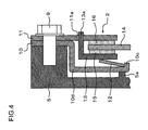
- FIG.4 depicts an enlarged partial radial cross-sectional view schematically showing the structure of a limiter unit in a torque fluctuation absorber according to Example 3 of the present disclosure.
- Fig.5 left and Fig.5 right depict enlarged radial partial cross-sectional views showing the structure of the limiter unit of the torque fluctuation absorber of Example 3 of the present disclosure before and after assembling on the flywheel, respectively.
- Example 3 both the diameter and the plate thickness of the conical spring (12 of Figs.2 and 3 ) are reduced, instead of reducing only its plate thickness, as in Examples 1 and 2, thereby reducing the cost.
- the conical spring 12 has its inner peripheral end abutted against the support plate 10, while having its outer peripheral end abutted against the pressure plate 13, specifically, against a position in a mid portion of an opposite side surface of the pressure plate having a length equal to the radial length of the friction material 15.
- the support plate 10 is extended radially more inwardly than the inner periphery of the conical spring 12, and includes at its extreme inner peripheral end a guide 10c protruded towards the pressure plate 13. The guide 10c prevents the radial movement of the conical spring 12.
- the support plate 10 Before assemblage to the flywheel 5, the support plate 10 has its inner peripheral extreme end tilted towards the flywheel 5. After assemblage of the support plate 10 to the flywheel 5, the support plate 10 has its flexure part 10d flexed so that its inner peripheral extreme end is thrust against a protrusion 5a of the flywheel 5 (see Fig.5 ).
- the support plate 10 is provided with slits or bends to prevent that the flexure part 10d of the support plate is plastically deformed.
- the protrusion 5a of the flywheel 5 is provided at a position on an opposite side of the support plate 10 with respect to the position of abutment of the inner peripheral extreme end of the conical spring against the support plate.
- the present Example is similar in structure to Example 1.
- Example 3 the outer peripheral extreme end of the conical spring 12 abuts against the pressure plate 13, specifically, against a position in a mid portion of an opposite side surface of the pressure plate having a length equal to the radial length of the friction material 15. Hence, the diameter of the conical spring 12 may be reduced. The amount of use of the expensive spring steel material may thus be reduced to lower the cost of the device. Since the diameter of the conical spring 12 is reduced, the thrust load of the conical spring 12 may be increased to allow reducing the plate thickness of the conical spring 12. Since the amount of the expensive spring steel material to be in use may be reduced, the cost of the entire device may be lowered.
- the support plate 10 is thrust against and supported by the flywheel 5 after assemblage thereof to the flywheel 5, it is unnecessary to increase the strength of the support plate 10. Since the plate thickness of the support plate 10 may thus be reduced, the amount of the steel material may be reduced to lower the cost of the entire device.
- Fig.6 depicts an enlarged partial radial cross-sectional view schematically showing the structure of a limiter unit in the torque fluctuation absorber according to Example 4 of the present disclosure.
- the Example 4 is a modification of Example 3 (see Fig.4 ).
- the support plate 10 is not thrust against or carried by the flywheel 5, as in Example 3. Instead, steps 10e, 10f are provided to improve the strength of the support plate 10.
- the conical spring 12 has its inner peripheral extreme end abutted against the support plate 10, while having its outer peripheral extreme end abutted against the pressure plate 13, specifically, against a position in a mid portion of an opposite side surface of the pressure plate having a length equal to the mid portion of the radial length of the friction material 15.
- the support plate 10 is extended more radially inwardly than the conical spring 12, and has a guide 10c at its inner peripheral extreme end.
- the guide 10c is protruded towards the pressure plate 13 to prevent radial movement of the conical spring 12.
- the support plate 10 is provided with the steps 10e, 10f at its mid portion which supports the conical spring 12 and which is thus liable to become deformed.
- the function of the steps 10e, 10f is to reduce flexure of the support plate 10 in the axial direction.
- the support plate 10 is provided with the two steps 10e, 10f only by way of illustration.
- the steps 10e, 10f may be arrayed circumferentially in series, that is, each extending along a radial direction, not only being arrayed radially in series.
- the support plate 10 is not provided with slits or bends, as in Example 3.
- the pressure plate 13 is provided with a circumferentially extending protrusion 13b which is located radially more outwardly than the abutment surface thereof with the outer peripheral extreme end of the conical spring 12.
- the circumferentially protrusion 13b prevents radial movement of the conical spring 12.
- the present Example is similar to Example 1.
- Example 4 the outer peripheral extreme end of the conical spring 12 abuts against the pressure plate 13, specifically, against a position in a mid portion of an opposite side surface of the pressure plate having a length equal to the mid portion of the radial length of the friction material 15. Hence, the diameter of the conical spring 12 may be reduced. Since the amount of the expensive spring steel material to be in use may be reduced, the cost of the entire device may be lowered. In addition, since the diameter of the conical spring 12 is reduced, the thrust load of the conical spring 12 may be increased to allow reducing the plate thickness of the conical spring 12. Since the amount of the expensive spring steel material to be in use may be reduced, the cost of the entire device may be lowered. In addition, since the support plate 10 is provided with the steps 10e, 10f, the strength of the support plate 10 may be maintained even if the plate thickness of the support plate 10 is reduced. Since the amount of steel material may be reduced, the cost of the entire device may be reduced.
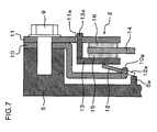
- FIG.7 depicts an enlarged partial radial cross-sectional view schematically showing the structure of a limiter unit in a torque fluctuation absorber according to Example 5 of the present disclosure.
- Example 5 is a modification of Example 3 (see Fig.4 ).
- An inner peripheral extreme end of the conical spring 12 is provided with an abutment 12a.
- the abutment 12a rests on the protrusion 5a of the flywheel 5.
- the outer peripheral extreme end of the conical spring 12 is abutted against the pressure plate 13.
- the inner peripheral extreme end of the support plate 10 is provided with a plurality of rotation stops 10g.
- the conical spring 12 is engaged relatively non-rotatably with the rotation stops 10g of the support plate 10, and is prevented in its radial movement by these rotation stops 10g.
- the present Example is similar to Example 1.
- the outer peripheral extreme end of the conical spring 12 is abutted against the pressure plate 13, specifically, against a position in a mid portion of an opposite side surface of the pressure plate having a length equal to the radial length of the friction material 15.
- the diameter of the conical spring 12 may be reduced. Since the amount of use of the expensive spring steel material may be reduced, the cost of the device may be lowered.
- the thrust load of the conical spring 12 may be increased to allow the plate thickness of the conical spring 12 to be reduced. Since the amount of the expensive spring steel material to be in use may be reduced, the cost of the entire device may be lowered.
- the inner peripheral extreme end of the conical spring 12 (extreme end of the rotation stop part l0a) is supported by the flywheel 5 (protrusion 5a), it is unnecessary to elevate the strength of the support plate 10, and hence the plate thickness of the support plate 10 may be reduced. Since the amount of the steel material used may be reduced, the cost of the entire device may be lowered.
- FIG.8 depicts an enlarged partial radial cross-sectional view (cross-section taken along lines X-X' of Figs.9 and 10 ) schematically showing the structure of a limiter unit in the torque fluctuation absorber according to Example 6 of the present disclosure.
- Fig.9 depicts an enlarged partial radial cross-sectional view schematically showing the structure of a pressure plate of the limiter unit in the torque fluctuation absorber according to Example 6 of the present disclosure.
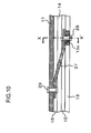
- Fig.10 depicts an enlarged partial radial cross-sectional view (cross-section taken along lines Y-Y' of Figs.8 and 9 ) schematically showing the structure of the limiter unit in the torque fluctuation absorber according to Example 6 of the present disclosure.
- Fig.11 depicts an enlarged partial radial cross-sectional view schematically showing the structure of the limiter unit in the torque fluctuation absorber according to Example 6 of the present disclosure.
- Example 6 the conical spring 12, used in Examples 1 to 5, is not used. Instead, a less expensive sheet spring 27 is used. Also, in Example 6, the support plate (10 of Fig.2 ) is not used and, instead, the sheet spring 27 is coupled by rivets 28, 29 to the pressure plate 13 and to the cover plate 11, respectively. Otherwise, the present Example is similar to Example 1.
- the cover plate 11 is an annular member fastened by the bolt(s) 9 to the flywheel 5, and is a component part of the limiter unit 2. An inner peripheral part of the cover plate 11 is spaced apart from the support plate 10.
- the cover plate 11 includes an inner peripheral slide surface by which it is slidably pressed on the friction material 16.
- the cover plate 11 is fastened by rivet 29 to the sheet spring 27 at a portion between the site of the cover plate fastened by the bolt 9 and the slide surface thereof against the friction material 16.
- the pressure plate 13 is an annular member slidably pressed on the friction material 15, and is a component member of the limiter unit 2.
- the pressure plate 13 is provided with an outer peripheral protrusion 13c at a preset position(s) on its outer peripheral extreme end (see Fig.9 ).
- the sheet spring 27 is fastened by rivet 28 to the outer peripheral protrusion 13c.
- the pressure plate 13 is biased by the sheet spring 27 towards the friction material 15.
- the sheet spring 27 is arranged between the cover plate 11 and the outer peripheral protrusion 13c of the pressure plate 13, and is a component part of the limiter unit 12.
- the sheet spring 27 biases the pressure plate 13 towards the friction material 15.
- the sheet spring 27 is extended in the circumferential direction (see Fig.9 ) with its mid portion traversing the outer periphery of the lining plate 14 and the friction materials 15, 16 at a spaced apart relation therefrom (see Fig. 10 ).
- the sheet spring 27 has its one end secured by rivet 28 to the outer peripheral protrusion 13c of the pressure plate 13, while having its other end secured by rivet 29 to the cover plate 11.
- the rivet 28 is a member that secures the one end of the sheet spring 27 to the outer peripheral protrusion 13c of the pressure plate 13.
- the rivet 29 is a member that secures the other end of the sheet spring 27 to the cover plate 11.
- Figs.8 to 10 the other end of the sheet spring 27 is secured to the cover plate 11. It is however also possible to provide the support plate 10 between the flywheel 5 and the cover plate 11 and to connect the sheet spring 27 via the rivets 28, 29 to the pressure plate 13 and to the support plate 10, as shown in Fig.11 .
- Example 6 in which the sheet spring 27, higher in yield than a conical spring 12, is used, the entire device may be lowered in cost. Moreover, since the sheet spring 27 has the torque transmitting function, a rotation stop mechanism that halts rotation of the pressure plate 13 relative to the cover plate 11 (protrusion 13a and the hole 11a of Fig.2 ) may be dispensed with, thereby reducing the cost and the space. If the support plate (10 of Fig.11 ) is not used, as in Figs.8 to 10 , the number of component parts may be reduced to further reduce the cost.
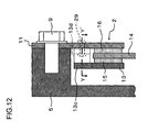
- FIG.12 depicts an enlarged partial radial cross-sectional view (cross-section taken along lines X-X' of Figs.13 and 14 ) schematically showing the structure of a limiter unit in the torque fluctuation absorber according to Example 7 of the present disclosure.
- Fig.13 depicts a plan view schematically showing the structure of a pressure plate of the limiter unit in the torque fluctuation absorber according to Example 7.
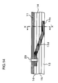
- Fig.14 depicts an enlarged partial radial cross-sectional view (cross-section taken along lines Y-Y' of Figs.12 and 13 ) schematically showing the structure of the limiter unit in the torque fluctuation absorber according to Example 7.
- Example 7 is a modification of Example 6 (see Figs.8 to 10 ).
- the sheet spring (27 of Fig.9 ) and the rivet (28 of Fig.9 ) in Example 6 are unified to the pressure plate 13.
- the present Example is similar to Example 6.
- the pressure plate 13 is a member slidably pressed on the friction material 15, and is a component member of the limiter unit 2.
- the pressure plate 13 includes a plurality of the outer peripheral protrusions 13c at preset outer peripheral positions (see Fig. 13 ).
- Each outer peripheral protrusion 13c includes a circumferential extension 13d along its outer periphery.
- the circumferential extension 13d acts as a sheet (plate) spring to bias the main part of the pressure plate 13 towards the friction material 15.
- the circumferential extension 13d traverses the outer periphery of the liming plate 14 and the friction materials 15, 16 at a spaced apart relation therefrom (see Fig. 14 ), and has its foremost part secured to the cover plate 11 by the rivet 29.
- the pressure plate 13 has the function of the sheet spring, it is possible to reduce the number of component parts and hence the cost. Moreover, since the circumferential extension 13d of the pressure plate 13 has the torque transmitting function, the rotation stop system of halting the rotation of the pressure plate 13 with respect to the cover plate 11 (protrusion 13a and the hole 11a of Fig.2 ) may be dispensed with. Hence, the cost as well as the space may be reduced. If the support plate (10 of Fig.11 ) is not used, as in Figs.12 to 14 , the number of component parts may be reduced to further reduce the cost.
- FIG.15 depicts an enlarged partial radial cross-sectional view (cross-section taken along lines X-X' of Figs.16 and 17 ) schematically showing the structure of a limiter unit in the torque fluctuation absorber according to Example 8 of the present disclosure.
- Fig.16 depicts a plan view schematically showing the structure of a pressure plate of the limiter unit in the torque fluctuation absorber according to Example 8 of the present disclosure.
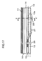
- Fig.17 depicts an enlarged partial radial cross-sectional view (cross-section taken along lines Y-Y' of Figs.15 and 16 ) schematically showing the structure of the limiter unit in the torque fluctuation absorber according to Example 8.
- Example 8 is a modification of Example 6 (modification shown in Fig.11 ).
- the sheet spring 27 is connected to the pressure plate 13 at a location located radially more inwardly than the slide surface of the pressure plate 13 with respect to the friction material 15.
- the present Example is similar to Example 6 (modification).
- the pressure plate 13 is an annular member slidably pressed on the friction material 15, and is a component part of the limiter unit 2.
- the pressure plate 13 includes a plurality of inner peripheral protrusions 13e at preset inner peripheral end positions (see Fig.16 ). These inner peripheral protrusions 13e are secured by rivets 28 to the sheet spring 27. The pressure plate 13 is biased by the sheet spring 27 towards the friction material 15.
- the sheet spring 27 is provided between the support plate 10 and the outer peripheral protrusion 13c of the pressure plate 13, and is a component part of the limiter unit 2.
- the sheet spring 27 biases the pressure plate 13 towards the friction material 15.
- a mid area of the sheet spring 27 traverses the outer rim of the pressure plate 13 (see Fig.16 ) in a spaced apart relationship therefrom (see Fig.17 ).
- the sheet spring 27 has its one end secured by the rivet 28 to the inner peripheral protrusion 13e of the pressure plate 13, while having its other end secured by the rivet 29 to a surface of the support plate 10 facing the cover plate 11.
- Example 8 in which the sheet spring 27, higher in yield than a conical spring 12, is used, the entire device may be lowered in cost. Moreover, since the sheet spring 27 has a torque transmitting function, the rotation stop mechanism that halts the rotation of the pressure plate 13 relative to the cover plate 11 (protrusion 13a and the hole 11a of Fig.2 ) may be dispensed with, thereby reducing the cost and the space. In addition, the site of connection of the sheet spring 27 to the pressure plate 13 is located radially more inwardly than the slide surface of the pressure plate 13 relative to the friction material 15, and hence the pressure plate 13 may be reduced in diameter. The amount of steel material to be in use may thus be reduced, thereby further reducing the cost and the space.
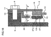
- FIG.18 depicts an enlarged partial radial cross-sectional view (cross-section taken along lines X-X' of Figs.19 and 20 ) schematically showing the structure of a limiter unit in the torque fluctuation absorber according to Example 9 of the present disclosure.
- Fig.19 depicts a plan view schematically showing the structure of a pressure plate of the limiter unit in the torque fluctuation absorber according to Example 9 of the present disclosure.
- Fig.20 depicts an enlarged partial radial cross-sectional view (cross-section taken along lines Y-Y' of Figs.18 and 19 ) schematically showing the structure of the limiter unit in the torque fluctuation absorber according to Example 9.
- Example 9 modified from Example 8 (see Figs. 15 to 17 ), no rivet is used for interconnecting the sheet spring 27 and the pressure plate 13. Instead, protrusions 13 f are formed on the pressure plate 13, and a hole 27a, mating with the protrusion 13f, is bored in the sheet spring 27.
- the sheet spring 27 is secured by the rivets 29 at two points to the support plate 10.
- the protrusion 13f of the pressure plate 13 is projected towards the flywheel 5.
- the protrusion 13f is introduced into the hole 27a of the sheet spring 27 to prevent its movement in the circumferential and radial directions is prevented.
- the present Example is similar to Example 8.
- Example 9 in which the sheet spring 27, higher in yield than a conical spring 12, is used, the entire device may be lowered in cost. Moreover, since the sheet spring 27 has a torque transmitting function, a rotation stop unit that halts rotation of the pressure plate 13 relative to the cover plate 11 (protrusion 13a and the hole 11a of Fig.2 ) may be dispensed with, thereby reducing the cost and the space. In addition, since the sheet spring 27 and the pressure plate 13 are interconnected by having the protrusion 13f of the pressure plate 13 engaged in the hole 27a of the sheet spring 27, the pressure plate 13 may be reduced in diameter. Hence, the amount of the steel material to be in use may be reduced, thereby reducing the cost of the device and space.
- FIG.21 depicts an enlarged partial radial cross-sectional view (cross-section taken along line X-X' of Fig.22 ) schematically showing the structure of a limiter unit in the torque fluctuation absorber according to Example 10 of the present disclosure.
- Fig.22 is a plan view schematically showing the structure of a pressure plate of the limiter unit of the torque fluctuation absorber according to Example 10.
- Example 10 modified from Example 1 (see Fig.2 ), a plurality of conical springs 31, each being of a smaller diameter corresponding to the radial extent of the friction material 15, are used in place of a sole conical spring of a larger diameter (12 of Fig.2 ) as in Example 1.
- the pressure plate 13 includes a plurality of protrusions 13f mating with holes bored in the inner rim of the conical springs 31. The protrusions 13f prevent the movement of the conical springs 31 in the circumferential and radial directions.
- the inner peripheral ends of the conical springs 31 abut against the portions of the pressure plate 13 located on the outer periphery of the protrusions 13f of the pressure plate 13, with the outer peripheral ends of the conical springs 31 abutting against the support plate 10.
- the conical springs 31 bias the pressure plate 13 towards the friction material 15.
- the center axis of the conical spring 31 is located in an area of the portion of the pressure plate 13 axially facing the lining plate 14, viz., within the extent of the radial length of the friction material 15.
- the present Example is similar to Example 8.
- the conical spring 31 has the inner peripheral end abutted against the outer peripheral area of the protrusion 13f of the pressure plate 13, while having the outer peripheral end abutted against the support plate 10.
- the conical spring 31 may also have the outer peripheral end abutted against the outer peripheral area of the protrusion 13f of the pressure plate 13, while having the inner peripheral end abutted against the support plate 10.
- a protrusion like the protrusion 13f provided on the pressure plate 13 is preferably formed on the support plate 10.
- Example 10 in which the multiple conical springs 31 of smaller diameters are used, the yield of the spring steel material may be improved, thus reducing the cost of the entire device.
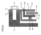
- FIG.23 depicts an enlarged partial radial cross-sectional view schematically showing the structure of a limiter unit in the torque fluctuation absorber according to Example 11 of the present disclosure.
- Example 11 modified from Example 10 (see Figs.21 and 22 ), a plurality of coil springs 32 of smaller diameters are used in place of the multiple conical springs of smaller diameters.
- the pressure plate 13 includes a plurality of protrusions 13f mating with the inner peripheral bores in the coil springs 32. The protrusions 13f prevent circumferential and radial movements of the coil springs 32.
- Each coil spring 32 has its one end abutted against the pressure plate 13 in an area of an outer periphery of the protrusion 13f of the pressure plate 13, while having its outer peripheral end abutted against the support plate 10.
- Each coil spring 32 biases the pressure plate 13 towards the friction material 15.
- the center axis of the coil spring 32 is located within the area of axial opposition of the pressure plate 13 to the lining plate 14, that is, within the extent of the radial length of the friction material 15.
- the Example 11 is similar to Example 10.
- the protrusions 13f is provided on the pressure plate 13.
- the protrusion may, however, be provided on only the support plate 10, or on each of the pressure plate 13 and the support plate 10.
- Example 11 in which the coil springs 32 of smaller diameters are used, the production yield may be improved, thus lowering the cost of the entire device.
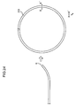
- FIG.24 left depicts an enlarged partial radial cross-sectional view schematically showing the structure of a conical spring 12 of a limiter unit in the torque fluctuation absorber according to Example 12 of the present disclosure, during its preparation
- Fig.24 right depicts a similar enlarged partial radial cross-sectional view schematically showing the structure of the conical spring after completion
- Fig.25 depicts an enlarged partial radial cross-sectional view schematically showing the structure of a modification of the conical spring 12 of the limiter unit in the torque fluctuation absorber according to Example 12 of the present disclosure.
- Example 12 modified from the conical spring 12 of Example 1 (12 of Fig.2 ), a conical spring 33, composed of a plain sheet-shaped steel material, is bent to form an annular conical shape for use in place of the non-interrupted conical spring (12 of Fig.2 ) of Example 1.
- the ends of the conical spring 33 are not joined together (i.e., forming free ends with or/without a gap).
- the inner peripheral end of the conical spring 33 abuts against the pressure plate (13 of Fig.2 ).
- the conical spring 33 biases the pressure plate 13 towards the friction material 15. Meanwhile, both circumferential ends of the conical spring 33 may overlap with each other (see Fig.25 ).
- Example 12 in which the conical spring 33, the ends of which are not joined to each other, is used, the yield of the spring steel material may be improved, thus reducing the cost. In addition, if both ends of the conical spring 33 are overlapped together, the load may be made even to allow a larger load to be produced.
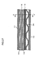
- FIG. 26 depicts an enlarged partial radial cross-sectional view (cross-section taken along line X-X' of Fig.27 ) schematically showing the structure of a limiter unit in the torque fluctuation absorber according to Example 13 of the present disclosure.
- Fig.27 depicts a similar enlarged partial radial cross-sectional view (cross-section taken along line Y-Y' of Fig.26 ) schematically showing the structure of the limiter unit in the torque fluctuation absorber according to Example 13.
- Fig. 13 modified from Example 1, uses a corrugated spring 34 in place of using a non-interrupted conical spring of Example 1 (12 of Fig.2 ).
- the corrugated spring 34 is obtained on forming a plane sheet-shaped spring steel material into an annular corrugated shape. The extreme ends of the corrugated spring 34 are not joined together.
- the corrugated spring 34 alternately abuts against the pressure plate 13 and the support plate 10.
- the portions of the corrugated spring 34 not abutting against the pressure plate 13 or the support plate 10 operate as a sheet spring.
- the corrugated spring 34 biases the pressure plate 13 towards the friction material 15.
- the corrugated spring 34 may be secured by a rivet, not shown, to the support plate 10, while the support plate 10 may be provided with the guide 10c shown in Fig.4 .
- the Example 11 is similar to Example 10.
- Example 13 in which the corrugated spring 34, whose extreme ends are not joined together, is used, the spring steel material may be improved in yield, while the cost of the entire product may be lowered. Moreover, the corrugated spring 34 is easier in forming than the conical spring.
- a torque fluctuation absorber includes a first plate member to which power of rotation is transmitted from a first rotational shaft, a second plate member arranged at a preset spacing from the first plate member, a third plate member arranged between the first plate member and the second plate member and configured to transmit power of rotation to a second rotational shaft.
- the torque fluctuation absorber also includes a fourth plate member arranged at a preset spacing from the second plate member, and a resilient member arranged between the second plate member and the fourth plate member and configured to bias the second plate member towards the third plate member.
- the fourth plate member includes a fulcrum point 10b that supports a mid portion of the resilient member.
Landscapes
- Engineering & Computer Science (AREA)
- General Engineering & Computer Science (AREA)
- Mechanical Engineering (AREA)
- Physics & Mathematics (AREA)
- Acoustics & Sound (AREA)
- Aviation & Aerospace Engineering (AREA)
- Mechanical Operated Clutches (AREA)
- Transmission Devices (AREA)
- One-Way And Automatic Clutches, And Combinations Of Different Clutches (AREA)
Abstract
Description
- This application is based on and claims priority under Paris Convention of Japanese Patent Application No.
2009-074051 filed on March 25, 2009 - This disclosure relates to a torque fluctuation absorber that takes up torque fluctuations between rotational shafts. More particularly, it relates to a torque fluctuation absorber having a limiter unit that produces slip when the fluctuating torque has reached a preset value.
- A torque fluctuation absorber is arranged e.g. on a power transmission path between an engine and a motor in e.g. a hybrid car to absorb or suppress the torque fluctuations caused in the engine and the motor. The torque fluctuation absorber may include a damper unit that takes up the torque fluctuations by a spring force, a hysteresis unit that absorbs or suppresses the torque fluctuations by the hysteresis torque caused by friction, and a limiter unit. The limiter unit produces slip when the torsion of the rotational shafts may no longer be taken up by the damper unit or the hysteresis unit.
- The limiter unit is composed of a friction material sandwiched between two plates. One of the plates is non-rotatable and axially movable with respect to the other. One of the plates is biased towards the friction material by a conical spring (see
Patent Publication 1, for example). The conical spring is arranged as a continuous annular member, and is inclined from an inner peripheral side towards an outer peripheral side.
[Patent Document] -
JP 2005-127507A Fig.2 ) - The entire disclosures of the above-mentioned
Patent Document 1 are incorporated herein by reference thereto. An analysis by the present disclosure will be given below.
The conical spring has an inner peripheral end abutted against a plate, while having an outer peripheral end supported by another plate. The inner peripheral end of the conical spring abuts against the former plate at a location substantially in register with a friction surface between a friction material and the former plate. As a result, the diameter of the conical spring is increased to elevate the cost of the conical spring and hence that of the entire device. The process of producing the conical spring is time-consuming. Moreover, the spring steel, as a material for the conical spring, is costly as compared to general steel material, thus elevating the cost of the conical spring and hence that of the entire device. In addition, the portion of the material located more radially inwardly than the inner peripheral end of the conical spring is discarded in the production step because of the larger inner diameter of the conical spring. Hence, the manufacture yield is low, with the result that the cost of the conical spring and hence that of the entire device are increased. - Accordingly, there is a need for a torque fluctuation absorber that may be produced at a reduced cost.
- In a first aspect, there is provided a torque fluctuation absorber comprising a first plate member to which power of rotation is transmitted from a first rotational shaft, a second plate member arranged at a preset distance from the first plate member, a third plate member arranged between the first and second plate members and configured to transmit power of rotation to a second rotational shaft, a fourth plate member arranged at a preset distance from the second plate member. The torque fluctuation absorber further comprises a resilient member arranged between the second plate member and the fourth plate member and configured to bias the second plate member towards the third plate member. At least one of the second plate member and the fourth plate member includes a fulcrum point that supports a mid portion of the resilient member.
- In a second aspect, there is provided a torque fluctuation absorber, comprising: a first plate member to which power of rotation is transmitted from a first rotational shaft; a second plate member arranged at a preset distance from the first plate member; a third plate member arranged between the first and second plate members and configured to transmit power of rotation to a second rotational shaft; and a fourth plate member arranged at a preset distance from the second plate member. The torque fluctuation absorber further comprises a resilient member arranged between the second plate member and the fourth plate member and configured to bias the second plate member towards the third plate member. The resilient member includes a first end located at a position having a preset distance from a center of rotation of the first rotational shaft and a second end located at a position more closely to the center of rotation of the first rotational shaft than the first end. The first end abuts against the second plate member in an area where the second plate member faces the third plate member in the axial direction. The second end abuts against the fourth plate member.
- In a third aspect, there is provided a torque fluctuation absorber, comprising: a first plate member to which the power of rotation is transmitted from a first rotational shaft; a second plate member arranged at a preset distance from the first plate member; a third plate member arranged between the first and second plate members and configured to transmit the power of rotation to a second rotational shaft; and a sheet spring biasing the second plate member towards the third plate member.
-
-
Fig.1 is a radial partial cross-sectional view schematically showing the structure of a torque fluctuation absorber according to Example 1 of the present disclosure. -
Fig.2 is an enlarged radial partial cross-sectional view schematically showing the structure of a limiter unit in the torque fluctuation absorber according to Example 1 of the present disclosure. -
Fig.3 is an enlarged radial partial cross-sectional view schematically showing the structure of a limiter unit in a torque fluctuation absorber according to Example 2 of the present disclosure. -
Fig.4 is an enlarged radial partial cross-sectional view schematically showing the structure of the limiter unit in the torque fluctuation absorber according to Example 2 of the present disclosure. -
Figs.5 left and right are enlarged radial partial cross-sectional views schematically showing the structure of a limiter unit in a torque fluctuation absorber according to Example 3 of the present disclosure, and showing the limiter unit before and after assemblage to a flywheel, respectively. -
Fig.6 is an enlarged radial partial cross-sectional view schematically showing the structure of a limiter unit in a torque fluctuation absorber according to Example 4 of the present disclosure. -
Fig.7 is an enlarged radial partial cross-sectional view schematically showing the structure of a limiter unit in a torque fluctuation absorber according to Example 5 of the present disclosure. -
Fig.8 is an enlarged radial partial cross-sectional view, corresponding to a cross-section taken along line X-X' ofFigs.9 and10 , and schematically showing the structure of a limiter unit in a torque fluctuation absorber according to Example 6 of the present disclosure. -
Fig.9 is a plan view schematically showing the structure of a pressure plate of the limiter unit in the torque fluctuation absorber according to Example 6 of the present disclosure. -
Fig.10 is an enlarged radial partial cross-sectional view, corresponding to a cross-section taken along line Y-Y' ofFigs.8 and9 , and schematically showing the structure of the limiter unit in the torque fluctuation absorber according to Example 6 of the present disclosure. -
Fig.11 is an enlarged radial partial cross-sectional view schematically showing the structure of the limiter unit in the torque fluctuation absorber according to Example 6 of the present disclosure. -
Fig.12 is an enlarged radial partial cross-sectional view, corresponding to a cross-section taken along line X-X' ofFigs. 13 and14 , and schematically showing the structure of a limiter unit in a torque fluctuation absorber according to Example 7 of the present disclosure. -
Fig.13 is a plan view schematically showing the structure of a pressure plate of the limiter unit in a torque fluctuation absorber according to Example 7 of the present disclosure. -
Fig.14 is an enlarged radial partial cross-sectional view, corresponding to a cross-section taken along line Y-Y' ofFigs. 12 and13 , and schematically showing the structure of the limiter unit in the torque fluctuation absorber according to Example 7 of the present disclosure. -
Fig. 15 is an enlarged radial partial cross-sectional view, corresponding to a cross-section taken along line X-X' ofFigs.16 and17 , and schematically showing the structure of a limiter unit in a torque fluctuation absorber according to Example 8 of the present disclosure. -
Fig.16 is a plan view schematically showing the structure of a pressure plate of the limiter unit in the torque fluctuation absorber according to Example 8 of the present disclosure. -
Fig.17 is an enlarged radial partial cross-sectional view, corresponding to a cross-section taken along line Y-Y' ofFigs. 15 and16 , and schematically showing the structure of the limiter unit in the torque fluctuation absorber according to Example 8 of the present disclosure. -
Fig.18 is an enlarged radial partial cross-sectional view, corresponding to a cross-section taken along line X-X' ofFigs.19 and20 , and schematically showing the structure of a limiter unit in a torque fluctuation absorber according to Example 9 of the present disclosure. -
Fig.19 is a plan view schematically showing the structure of a pressure plate of the limiter unit in the torque fluctuation absorber according to Example 9 of the present disclosure. -
Fig.20 is an enlarged radial partial cross-sectional view, corresponding to a cross-section taken along line Y-Y' ofFigs. 18 and19 , and schematically showing the structure of the limiter unit in the torque fluctuation absorber according to Example 9 of the present disclosure. -
Fig.21 is an enlarged radial partial cross-sectional view, corresponding to a cross-section taken along line X-X' ofFig.22 , and schematically showing the structure of a limiter unit in a torque fluctuation absorber according to Example 10 of the present disclosure. -
Fig.22 is a plan view schematically showing the structure of a pressure plate of the limiter unit in the torque fluctuation absorber according to Example 10 of the present disclosure. -
Fig.23 is an enlarged radial partial cross-sectional view schematically showing the structure of a limiter unit in a torque fluctuation absorber according to Example 11 of the present disclosure. -
Figs.24 left and right are enlarged radial partial cross-sectional views schematically showing the structure of a conical spring of a limiter unit, during and after manufacture, in a torque fluctuation absorber according to Example 12 of the present disclosure, respectively. -
Fig.25 is an enlarged radial partial cross-sectional view schematically showing the structure of a conical spring of the limiter unit in the torque fluctuation absorber according to Example 12 of the present disclosure. -
Fig.26 is an enlarged radial partial cross-sectional view, corresponding to a cross-section taken along line X-X' ofFig.27 , and schematically showing the structure of a limiter unit in a torque fluctuation absorber according to Example 13 of the present disclosure. -
Fig.27 is an enlarged radial partial cross-sectional view, corresponding to a cross-section taken along line Y-Y' ofFig.26 , and schematically showing the structure of the limiter unit in the torque fluctuation absorber according to Example 13 of the present disclosure. - The inner circumferential end of the conical spring shown by
JP2005-127507A Fig. 2 ) abuts to one plate, and the outer circumferential end is supported by the other plate. The inner circumferential end of the conical spring contacts with the one plate at a position corresponding to the friction surface of the friction material against the one plate. Therefore, the conical spring becomes large in diameter, increases its cost, resulting in an increased cost of the apparatus. Also, since the forming process for the conical spring is long and the spring steel used for conical spring is costly as compared to general steel material, the cost of the conical spring is increased, resulting in the increased cost of the apparatus. Further, since the inner diameter of the inner circumferential end of the conical spring is large, and the portion of radially internal of the inner circumferential end is discarded and yield becomes low, which offers the increased cost of the conical spring and also that of the apparatus.
In order to solve the aforementioned problem, various modes are possible according to the present disclosure. - According to the first aspect, the resilient member is preferably a conical spring.
- According to the first aspect, the fulcrum point is preferably a foremost part of a protrusion formed on at least one of the second plate member and the fourth plate member.
- According to the first aspect, the fulcrum point is preferably an angular part of a step formed on at least one of the second plate member and the fourth plate member.
- In the second aspect, the resilient member is preferably a conical spring.
- In the second aspect, the fourth plate member preferably includes a guide part in an area located radially more inwardly than the second end of the resilient member. The guide part prevents the movement of the resilient member in a direction towards the center of rotation of the first rotational shaft.
- In the second aspect, the second plate member preferably includes a guide part in an area located radially more outwardly than the first end of the resilient member. The guide part prevents the movement of the resilient member in a direction away from the center of rotation of the first rotational shaft.
- The torque fluctuation absorber according to the second aspect preferably includes a flywheel to which the first and fourth plate members are secured. The fourth plate member abuts against the flywheel in the vicinity of a portion of the fourth plate member abutting against the second end of the resilient member.
- In the second aspect, the fourth plate member preferably includes a slit(s) or a bend(s).
- The torque fluctuation absorber according to the second aspect preferably further comprises a flywheel to which the first and fourth plate members are secured. The resilient member may include an abutment protruded at the second end. The fourth plate member may include a rotation stop non-rotatably and radially non-movably engaged with the abutment. The abutment may abut against the flywheel.
- In the third aspect, the sheet spring preferably has one end secured to the second plate member, while having the other end secured to the first plate member.
- The torque fluctuation absorber according to the third aspect preferably further comprises a fourth plate member arranged at a preset distance from the second plate member. The sheet spring has one end secured to the second plate member, while having the other end secured to the fourth plate member.
- In the third aspect, the second plate member preferably has an inner peripheral protrusion. The one end of the sheet spring is secured to the inner peripheral protrusion of the second plate member.
- In the third aspect, the sheet spring preferably is a part of the second plate member. The foremost part of the sheet spring is secured to the first plate member.
- The torque fluctuation absorber according to the third aspect preferably further comprises a fourth plate member arranged at a preset distance from the second plate member. The sheet spring is a part of the second plate member, and the foremost part of the sheet spring is secured to the fourth plate member.
- The torque fluctuation absorber according to the third aspect preferably further comprises a fourth plate member arranged at a preset distance from the second plate member. The second plate member may include an axially directed protrusion.
The sheet spring may have both ends secured to the fourth plate member. The sheet spring may include a hole engaged by the protrusion of the second plate member. - In a fourth aspect, there is provided a torque fluctuation absorber, comprising: a first plate member to which power of rotation is transmitted from a first rotational shaft, a second plate member arranged at a preset distance from the first plate member, a third plate member arranged between the first and second plate members and configured to transmit power of rotation to a second rotational shaft, a fourth plate member arranged at a preset distance from the second plate member, and a plurality of resilient members arranged between the second plate member and the fourth plate member and configured to bias the second plate member towards the third plate member. Each of the resilient members has a center axis located in a region where the second plate member faces the third plate member along the axial direction.
- In the fourth aspect, the resilient member preferably is a conical spring.
- In the fourth aspect, the resilient member preferably is a coil spring.
- In the fourth aspect, the second plate member or the fourth plate member preferably includes a protrusion facing the resilient member. The protrusion may be introduced into an inner peripheral part of the resilient member.
- In a fifth aspect, there is provided a torque fluctuation absorber comprising: a first plate member to which power of rotation is transmitted from a first rotational shaft; a second plate member arranged at a preset distance from the first plate member; a third plate member arranged between the first and second plate members and configured to transmit power of rotation to a second rotational shaft; and a fourth plate member arranged at a preset distance from the second plate member. The torque fluctuation absorber further comprises a resilient member arranged between the second plate member and the fourth plate member and configured to bias the second plate member towards the third plate member. The resilient member is substantially annular and has both ends set apart from one another.
- In the fifth aspect, the resilient member preferably is formed like a saucer.
- In the fifth aspect, both ends of the resilient member preferably overlap each other along the circumferential direction.
- In the fifth aspect, the resilient member is preferably corrugated along a circumferential direction and alternately abuts against the second plate member and the fourth plate member.
- A torque fluctuation absorber according to Example 1 of the present disclosure will now be described with reference to the drawings.
Fig.1 depicts a partial radial cross-sectional view schematically showing the structure of the torque fluctuation absorber according to Example 1 of the present disclosure.Fig.2 depicts an enlarged partial radial cross-sectional view schematically showing the structure of the limiter unit in the torque fluctuation absorber according to Example 1 of the present disclosure. - The
torque fluctuation absorber 1 according to Example 1 is provided e.g. on a power transmission path between an engine siderotational shaft 6 and a transmission siderotational shaft 7. It is a device for absorbing (suppressing) the fluctuating torque caused by torsion between the engine siderotational shaft 6 and the transmission gear siderotational shaft 7. Thetorque fluctuation absorber 1 includes a damper unit(s) 3 having a torsion buffering function and configured for absorbing the fluctuating torque by spring force (force of resiliency), and ahysteresis unit 4 that absorbs (suppresses) the fluctuating torque by the hysteresis torque caused e.g. by friction. Thetorque fluctuation absorber 1 also includes a limiter unit(s) 2 that generates slip when the torsion of the rotational shaft has ceased to be absorbed by thedamper unit 3 or by thehysteresis unit 4. Thedamper unit 3 is arranged on the power transmission path in parallel with thehysteresis unit 4. Thelimiter unit 2 is arranged on the power transmission path in series with thedamper unit 3 and thehysteresis unit 4. Thetorque fluctuation absorber 1 may be used, in particular, for a hybrid car having no limiter unit in the car, and may also be useful for reducing the system size in a car not having the limiter unit. - The
torque fluctuation absorber 1 includes, as component parts, aflywheel 5, abolt 9, asupport plate 10, acover plate 11, aconical spring 12, apressure plate 13, alining plate 14,friction materials side plates rivet 19, acoil spring 20 and aseat member 21. In addition, the torque fluctuation absorber includes thrustmembers conical spring 24 and ahub member 25. - The
flywheel 5 is an annular plate member fastened by a bolt(s) 8 to the engine siderotational shaft 6. Theflywheel 5 has its periphery protruded towards thelimiter unit 2 to form a cylindrical portion. Thesupport plate 10 and thecover plate 11 are fastened by the bolt(s) 9 to this cylindrical portion. - The bolt(s) 9 is a member used for fastening the
support plate 10 and thecover plate 11 to theflywheel 5. - The
support plate 10 is an annular plate-like member arranged between theflywheel 5 and thecover plate 11, and is a structural part of thelimiter unit 2. Thesupport plate 10 is set at its periphery on thecover plate 11 and the two plates are secured together to theflywheel 5 by the bolt(s) 9. Thesupport plate 10 is separated at its inner peripheral part away from thecover plate 11, and includes astep 10a protruded at near its inner peripheral end towards thecover plate 11. The step may also be a protrusion. An outer peripheral bent edge of thestep 10a operates as afulcrum point 10b that supports a mid portion of an inclined surface of theconical spring 12 facing an inner peripheral side. - The
cover plate 11 is an annular member arranged on the opposite side of theflywheel 5 with respect to thesupport plate 10, viz., on the right side ofFig.1 , and is a component part of thelimiter unit 2. Thecover plate 11 is set at its outer peripheral part in contact with thesupport plate 10 and the two plates are secured together to the flywheel by the bolt(s) 9. Thecover plate 11 has its inner peripheral part separated away from thesupport plate 10. Thecover plate 11 includes a hole(s) 11a for supporting thepressure plate 13 in such a manner as to prevent relative rotation and to allow for axial movement of thepressure plate 13. Thepressure plate 13 includes aprotrusion 13a inserted relatively non-rotatably and axially movably into thehole 11a. Thecover plate 11 has a slide surface on its inner peripheral part by which the cover plate is slidably pressed on thefriction member 16. - The
conical spring 12 is a continuous saucer-shaped spring arranged between thesupport plate 10 and thepressure plate 13, and is a component part of thelimiter unit 2. Theconical spring 12 biases thepressure plate 13 towards thefriction material 15. An inner peripheral end of theconical spring 12 abuts against thepressure plate 13, and the mid part of an inclined surface of theconical spring 12, facing an inner peripheral side, abuts against thefulcrum point 10b of thestep 10a of thesupport plate 10. An outer peripheral end of theconical spring 12 is spaced apart from thesupport plate 10. Theconical spring 12 operates for pressuring thepressure plate 13 under assistance by the leverage action about thefulcrum point 10b. This amplifies the thrust load of theconical spring 12 against thepressure plate 13 to allow reducing the plate thickness of theconical spring 12. - The
pressure plate 13 is an annular member arranged between theconical spring 12 and thefriction material 15, and is a component part of thelimiter unit 2. Thepressure plate 13 includes aprotrusion 13a operative to prevent relative rotation and to allow for axial movement of thepressure plate 13 relative to thecover plate 11. Theprotrusion 13a is introduced through thehole 11a of thecover plate 11 so that the protrusion is unable to perform relative rotation but may perform axial movement. Thepressure plate 13 is biased towards thefriction material 15 by theconical spring 12 and is slidably pressed on its slide surface against thefriction material 15. - The lining
pate 14 is an annular member arranged between thefriction materials cover plate 11 and thepressure plate 13. The lining plate is a component part of thelimiter unit 2. An inner peripheral part of the liningpate 14 is sandwiched between theside plates side plates rivet 19. An outer peripheral part of the liningpate 14 is secured to thefriction materials - The
friction material 15 is a component part of thelimiter unit 2, and is arranged between the liningplate 14 and thepressure plate 13. Thefriction material 15 is secured to thelining plate 14 by a rivet or an adhesive, not shown. Thefriction material 15 is slidably pressed on thepressure plate 13. Thefriction material 15 used may include rubber, resins, fibers (short fibers or long fibers) or particles for adjusting the frictional coefficient µ. - The
friction material 16 is a component part of thelimiter unit 2, and is arranged between the liningplate 14 and thecover plate 11. Thefriction material 16 is secured to thelining plate 14 by a rivet or an adhesive, not shown, and is slidably pressed on thecover plate 11. - The
side plate 17 is an annular member arranged on an engine side of aflange part 25b of thehub member 25, viz., on the left side ofFig.1 , and is a component part of thedamper unit 3 and thehysteresis unit 4. Theside plate 17 is secured in the vicinity of an outer peripheral part thereof as one to thelining plate 14 and with theside plate 18 by therivet 19. In thedamper unit 3, located in an intermediate area, theside plate 17 includes awindow 17a in which acoil spring 20 and aseat member 21 are accommodated. The peripheral end face of thewindow 17a may be contacted with or separated away from theseat member 21. Theside plate 17 is slidably contacted with thefirst thrust member 22 in thehysteresis unit 4 which is located radially more inwardly than thedamper unit 3. Theside plate 17 has its inner peripheral end part carried by a hub member 25 (hub part 25a) for relative rotational movement via thethrust member 22. - The
side plate 18 is an annular member arranged on a transmission side of aflange part 25b of thehub member 25, viz., on the right side ofFig.1 , and is a component part of thedamper unit 3 and thehysteresis unit 4. Theside plate 18 is secured in the vicinity of an outer peripheral end part thereof by the rivet(s) 19 as one to the limingplate 14 and theside plate 17. In thedamper unit 3 in an intermediate area, theside plate 18 includes awindow 18a in which thecoil spring 20 and theseat member 21 are accommodated. The peripheral end face of thewindow 18a may be contacted with or separated away from theseat member 21. Theside plate 18 carries theconical spring 24 in thehysteresis unit 4 which is located radially more inwardly than thedamper unit 2. Theside plate 18 has its inner peripheral part carried by the hub member 25 (hub part 25a) for relative rotational movement via thethrust member 23. - The
rivet 19 is used for securing the limingplate 14, theside plate 17 and theside plate 18 together. - The
coil spring 20, a component part of thedamper unit 3, is accommodated within thewindow parts side plates hub member 25, respectively, and is contacted with theseat member 21 arranged on both ends. When theside plates hub member 25 perform relative rotational movement, thecoil spring 20 is contracted to absorb the shock caused by differential rotations of theside plates hub member 25. Thecoil spring 20 may be straight-shaped, or may be bent from the straight shape, with the bent parts being then put together. To allow for broad torsion, an arc spring, bent along a peripheral direction, may also be used. - The
seat member 21, a component part of thedamper unit 3, is accommodated within thewindow parts side plates flange part 25b). The seat member is arranged between the peripheral end faces of thewindow parts coil spring 20. To reduce the wear caused to thecoil spring 20, theseat member 21 may be formed of resin. - The
thrust member 22, a component part of thehysteresis unit 4, is an annular member arranged between theside plate 17 and thehub member 25. When seen in the axial direction, thethrust member 22 is arranged between theside plate 17 and theflange part 25b, and is slidably pressed on theside plate 17 and theflange part 25b. Thethrust member 22 is also located in the radial direction between theside plate 17 and thehub part 25a, and operates as a slide bearing (bush) configured for carrying theside plate 17 for rotation relative to thehub part 25a. - The
thrust member 23, a component part of thehysteresis unit 4, is an annular member arranged between theside plate 18 and thehub member 25. When seen in the axial direction, thethrust member 23 is arranged between aconical spring 24 and theflange part 25b, and is biased by theconical spring 24 towards theflange part 25b into slidably pressed on theflange part 25b. When seen in the radial direction, thethrust member 23 is located between theside plate 18 and thehub member 25a, and operates as a slide bearing (bush) for carrying theside plate 18 for rotation relative to thehub part 25a. - The
conical spring 24, a component part of thehysteresis unit 4, is arranged between thethrust member 23 and theside plate 18. It is a saucer-shaped spring that biases thesecond thrust member 23 towards theflange part 25b. - The
hub member 25, a component part of thedamper unit 3 and thehysteresis unit 4, outputs the power of rotation from thedamper unit 3 and thehysteresis unit 4 to the transmission. Thehub member 25 includes theflange part 25b extended from a preset outer peripheral site of thehub part 25a. An inner peripheral side of thehub part 25a is in splined engagement with the transmission siderotational shaft 7. An outer peripheral part of thehub part 25a carries theside plate 17 for relative rotational movement via thethrust member 22, while carrying theside plate 18 for relative rotational movement via thethrust member 23. In the outerperipheral damper unit 3, theflange part 25b includes thewindow 25c in which thecoil sprig 20 and theseat member 21 are accommodated. The peripheral end face of thewindow 25c is adapted to be contacted with or separated from theseat member 21. In thehysteresis unit 4, located more radially inwardly than thedamper unit 3, the axially extending surface of theflange part 25b is slidably sandwiched between theslide members - Meanwhile,
Fig.1 shows a torque fluctuation absorber composed of the damper unit, hysteresis unit and the limiter unit. The torque fluctuation absorber may, however, include solely the limiter unit. - In Example 1, the thrust load of the
conical spring 12 against thepressure plate 13 is amplified by the action of leverage about thefulcrum point 10b of thesupport plate 10, and hence the plate thickness of theconical spring 12 may be reduced. Hence, the amount of expensive spring steel to be in use may be reduced, thus decreasing the cost of the entire device. - A torque fluctuation absorber according to Example 2 of the present disclosure will now be described with reference to the drawings.
Fig.3 depicts an enlarged partial radial cross-sectional view schematically showing the structure of a limiter unit in the torque fluctuation absorber according to Example 2 of the present disclosure. - Example 2 is a modification of Example 1 (see
Fig.2 ), in which the step (10a ofFig.2 ) and the fulcrum point (10b ofFig.2 ) are dispensed with and a fulcrum point for theconical spring 12 is provided on the pressure plate (13 ofFig.2 ). An outer peripheral end of theconical spring 12 abuts against thesupport plate 10. A mid part of an inclined surface of theconical spring 12, facing an outer peripheral side, abuts against acircumferential protrusion 13b of thepressure plate 13. An inner peripheral end of theconical spring 12 is spaced apart from thepressure plate 13. Thecircumferential protrusion 13b is provided at a mid part of thepressure plate 13 for extending towards thesupport plate 10. The foremost part of thecircumferential protrusion 13b acts as a fulcrum point that supports the mid part of the inclined surface of theconical spring 12 facing an outer rim part of theconical spring 12. In other respects, the present Example is similar to Example 1. - In Example 2, the thrust load of the
conical spring 12 against thepressure plate 13 may be amplified by the action of leverage about thecircumferential protrusion 13b of thepressure plate 13, as a fulcrum point, thus allowing the plate thickness of theconical spring 12 to be reduced. Hence, the amount of expensive spring steel to be in use may be reduced, thus decreasing the cost of the entire device. - A torque fluctuation absorber according to Example 3 of the present disclosure will now be described with reference to the drawings.
Fig.4 depicts an enlarged partial radial cross-sectional view schematically showing the structure of a limiter unit in a torque fluctuation absorber according to Example 3 of the present disclosure.Fig.5 left andFig.5 right depict enlarged radial partial cross-sectional views showing the structure of the limiter unit of the torque fluctuation absorber of Example 3 of the present disclosure before and after assembling on the flywheel, respectively. - In Example 3, both the diameter and the plate thickness of the conical spring (12 of
Figs.2 and3 ) are reduced, instead of reducing only its plate thickness, as in Examples 1 and 2, thereby reducing the cost. Theconical spring 12 has its inner peripheral end abutted against thesupport plate 10, while having its outer peripheral end abutted against thepressure plate 13, specifically, against a position in a mid portion of an opposite side surface of the pressure plate having a length equal to the radial length of thefriction material 15. Thesupport plate 10 is extended radially more inwardly than the inner periphery of theconical spring 12, and includes at its extreme inner peripheral end aguide 10c protruded towards thepressure plate 13. Theguide 10c prevents the radial movement of theconical spring 12. Before assemblage to theflywheel 5, thesupport plate 10 has its inner peripheral extreme end tilted towards theflywheel 5. After assemblage of thesupport plate 10 to theflywheel 5, thesupport plate 10 has itsflexure part 10d flexed so that its inner peripheral extreme end is thrust against aprotrusion 5a of the flywheel 5 (seeFig.5 ). Thesupport plate 10 is provided with slits or bends to prevent that theflexure part 10d of the support plate is plastically deformed. Theprotrusion 5a of theflywheel 5 is provided at a position on an opposite side of thesupport plate 10 with respect to the position of abutment of the inner peripheral extreme end of the conical spring against the support plate. In other respects, the present Example is similar in structure to Example 1. - In Example 3, the outer peripheral extreme end of the
conical spring 12 abuts against thepressure plate 13, specifically, against a position in a mid portion of an opposite side surface of the pressure plate having a length equal to the radial length of thefriction material 15. Hence, the diameter of theconical spring 12 may be reduced. The amount of use of the expensive spring steel material may thus be reduced to lower the cost of the device. Since the diameter of theconical spring 12 is reduced, the thrust load of theconical spring 12 may be increased to allow reducing the plate thickness of theconical spring 12. Since the amount of the expensive spring steel material to be in use may be reduced, the cost of the entire device may be lowered. In addition, since thesupport plate 10 is thrust against and supported by theflywheel 5 after assemblage thereof to theflywheel 5, it is unnecessary to increase the strength of thesupport plate 10. Since the plate thickness of thesupport plate 10 may thus be reduced, the amount of the steel material may be reduced to lower the cost of the entire device. - A torque fluctuation absorber according to Example 4 of the present disclosure will now be described with reference to the drawings.
Fig.6 depicts an enlarged partial radial cross-sectional view schematically showing the structure of a limiter unit in the torque fluctuation absorber according to Example 4 of the present disclosure. - The Example 4 is a modification of Example 3 (see
Fig.4 ). In the present Example, thesupport plate 10 is not thrust against or carried by theflywheel 5, as in Example 3. Instead, steps 10e, 10f are provided to improve the strength of thesupport plate 10. Theconical spring 12 has its inner peripheral extreme end abutted against thesupport plate 10, while having its outer peripheral extreme end abutted against thepressure plate 13, specifically, against a position in a mid portion of an opposite side surface of the pressure plate having a length equal to the mid portion of the radial length of thefriction material 15. Thesupport plate 10 is extended more radially inwardly than theconical spring 12, and has aguide 10c at its inner peripheral extreme end. Theguide 10c is protruded towards thepressure plate 13 to prevent radial movement of theconical spring 12. Thesupport plate 10 is provided with thesteps conical spring 12 and which is thus liable to become deformed. The function of thesteps support plate 10 in the axial direction. InFig.6 , thesupport plate 10 is provided with the twosteps steps support plate 10 is not provided with slits or bends, as in Example 3. Thepressure plate 13 is provided with acircumferentially extending protrusion 13b which is located radially more outwardly than the abutment surface thereof with the outer peripheral extreme end of theconical spring 12. Thecircumferentially protrusion 13b prevents radial movement of theconical spring 12. In other respects, the present Example is similar to Example 1. - In Example 4, the outer peripheral extreme end of the
conical spring 12 abuts against thepressure plate 13, specifically, against a position in a mid portion of an opposite side surface of the pressure plate having a length equal to the mid portion of the radial length of thefriction material 15. Hence, the diameter of theconical spring 12 may be reduced. Since the amount of the expensive spring steel material to be in use may be reduced, the cost of the entire device may be lowered. In addition, since the diameter of theconical spring 12 is reduced, the thrust load of theconical spring 12 may be increased to allow reducing the plate thickness of theconical spring 12. Since the amount of the expensive spring steel material to be in use may be reduced, the cost of the entire device may be lowered. In addition, since thesupport plate 10 is provided with thesteps support plate 10 may be maintained even if the plate thickness of thesupport plate 10 is reduced. Since the amount of steel material may be reduced, the cost of the entire device may be reduced. - A torque fluctuation absorber according to Example 5 of the present disclosure will now be described with reference to the drawings.
Fig.7 depicts an enlarged partial radial cross-sectional view schematically showing the structure of a limiter unit in a torque fluctuation absorber according to Example 5 of the present disclosure. - Example 5 is a modification of Example 3 (see
Fig.4 ). An inner peripheral extreme end of theconical spring 12 is provided with anabutment 12a. Theabutment 12a rests on theprotrusion 5a of theflywheel 5. The outer peripheral extreme end of theconical spring 12 is abutted against thepressure plate 13. The inner peripheral extreme end of thesupport plate 10 is provided with a plurality of rotation stops 10g. Theconical spring 12 is engaged relatively non-rotatably with the rotation stops 10g of thesupport plate 10, and is prevented in its radial movement by these rotation stops 10g. In other respects, the present Example is similar to Example 1. - In the present Example 5, the outer peripheral extreme end of the
conical spring 12 is abutted against thepressure plate 13, specifically, against a position in a mid portion of an opposite side surface of the pressure plate having a length equal to the radial length of thefriction material 15. Hence, the diameter of theconical spring 12 may be reduced. Since the amount of use of the expensive spring steel material may be reduced, the cost of the device may be lowered. Moreover, since the diameter of theconical spring 12 is reduced, the thrust load of theconical spring 12 may be increased to allow the plate thickness of theconical spring 12 to be reduced. Since the amount of the expensive spring steel material to be in use may be reduced, the cost of the entire device may be lowered. In addition, since the inner peripheral extreme end of the conical spring 12 (extreme end of the rotation stop part l0a) is supported by the flywheel 5 (protrusion 5a), it is unnecessary to elevate the strength of thesupport plate 10, and hence the plate thickness of thesupport plate 10 may be reduced. Since the amount of the steel material used may be reduced, the cost of the entire device may be lowered. - A torque fluctuation absorber according to Example 6 of the present disclosure will now be described with reference to the drawings.
Fig.8 depicts an enlarged partial radial cross-sectional view (cross-section taken along lines X-X' ofFigs.9 and10 ) schematically showing the structure of a limiter unit in the torque fluctuation absorber according to Example 6 of the present disclosure.Fig.9 depicts an enlarged partial radial cross-sectional view schematically showing the structure of a pressure plate of the limiter unit in the torque fluctuation absorber according to Example 6 of the present disclosure.Fig.10 depicts an enlarged partial radial cross-sectional view (cross-section taken along lines Y-Y' ofFigs.8 and9 ) schematically showing the structure of the limiter unit in the torque fluctuation absorber according to Example 6 of the present disclosure.
Fig.11 depicts an enlarged partial radial cross-sectional view schematically showing the structure of the limiter unit in the torque fluctuation absorber according to Example 6 of the present disclosure. - In Example 6, the
conical spring 12, used in Examples 1 to 5, is not used. Instead, a lessexpensive sheet spring 27 is used. Also, in Example 6, the support plate (10 ofFig.2 ) is not used and, instead, thesheet spring 27 is coupled byrivets pressure plate 13 and to thecover plate 11, respectively. Otherwise, the present Example is similar to Example 1. - The
cover plate 11 is an annular member fastened by the bolt(s) 9 to theflywheel 5, and is a component part of thelimiter unit 2. An inner peripheral part of thecover plate 11 is spaced apart from thesupport plate 10. Thecover plate 11 includes an inner peripheral slide surface by which it is slidably pressed on thefriction material 16. Thecover plate 11 is fastened byrivet 29 to thesheet spring 27 at a portion between the site of the cover plate fastened by thebolt 9 and the slide surface thereof against thefriction material 16. - The
pressure plate 13 is an annular member slidably pressed on thefriction material 15, and is a component member of thelimiter unit 2. Thepressure plate 13 is provided with an outerperipheral protrusion 13c at a preset position(s) on its outer peripheral extreme end (seeFig.9 ). Thesheet spring 27 is fastened byrivet 28 to the outerperipheral protrusion 13c. Thepressure plate 13 is biased by thesheet spring 27 towards thefriction material 15. - The
sheet spring 27 is arranged between thecover plate 11 and the outerperipheral protrusion 13c of thepressure plate 13, and is a component part of thelimiter unit 12. Thesheet spring 27 biases thepressure plate 13 towards thefriction material 15. Thesheet spring 27 is extended in the circumferential direction (seeFig.9 ) with its mid portion traversing the outer periphery of thelining plate 14 and thefriction materials Fig. 10 ). Thesheet spring 27 has its one end secured byrivet 28 to the outerperipheral protrusion 13c of thepressure plate 13, while having its other end secured byrivet 29 to thecover plate 11. - The
rivet 28 is a member that secures the one end of thesheet spring 27 to the outerperipheral protrusion 13c of thepressure plate 13. - The
rivet 29 is a member that secures the other end of thesheet spring 27 to thecover plate 11. - In
Figs.8 to 10 , the other end of thesheet spring 27 is secured to thecover plate 11. It is however also possible to provide thesupport plate 10 between theflywheel 5 and thecover plate 11 and to connect thesheet spring 27 via therivets pressure plate 13 and to thesupport plate 10, as shown inFig.11 . - In Example 6, in which the
sheet spring 27, higher in yield than aconical spring 12, is used, the entire device may be lowered in cost. Moreover, since thesheet spring 27 has the torque transmitting function, a rotation stop mechanism that halts rotation of thepressure plate 13 relative to the cover plate 11 (protrusion 13a and thehole 11a ofFig.2 ) may be dispensed with, thereby reducing the cost and the space. If the support plate (10 ofFig.11 ) is not used, as inFigs.8 to 10 , the number of component parts may be reduced to further reduce the cost. - A torque fluctuation absorber according to Example 7 of the present disclosure will now be described with reference to the drawings.
Fig.12 depicts an enlarged partial radial cross-sectional view (cross-section taken along lines X-X' ofFigs.13 and14 ) schematically showing the structure of a limiter unit in the torque fluctuation absorber according to Example 7 of the present disclosure.
Fig.13 depicts a plan view schematically showing the structure of a pressure plate of the limiter unit in the torque fluctuation absorber according to Example 7.Fig.14 depicts an enlarged partial radial cross-sectional view (cross-section taken along lines Y-Y' ofFigs.12 and13 ) schematically showing the structure of the limiter unit in the torque fluctuation absorber according to Example 7. - Example 7 is a modification of Example 6 (see
Figs.8 to 10 ). In the present Example 7, the sheet spring (27 ofFig.9 ) and the rivet (28 ofFig.9 ) in Example 6 are unified to thepressure plate 13. In other respects, the present Example is similar to Example 6. - The
pressure plate 13 is a member slidably pressed on thefriction material 15, and is a component member of thelimiter unit 2. Thepressure plate 13 includes a plurality of the outerperipheral protrusions 13c at preset outer peripheral positions (seeFig. 13 ). Each outerperipheral protrusion 13c includes acircumferential extension 13d along its outer periphery. Thecircumferential extension 13d acts as a sheet (plate) spring to bias the main part of thepressure plate 13 towards thefriction material 15. Thecircumferential extension 13d traverses the outer periphery of the limingplate 14 and thefriction materials Fig. 14 ), and has its foremost part secured to thecover plate 11 by therivet 29. - In
Figs.12 to 14 , the foremost part of thecircumferential extension 13d of thepressure plate 13 is secured to thecover plate 11. It is however also possible to provide thesupport plate 10 between theflywheel 5 and thecover plate 11, and to connect the foremost part of thecircumferential extension 13d of thepressure plate 13 to thesupport plate 10. - In the present Example 7, in which the
pressure plate 13 has the function of the sheet spring, it is possible to reduce the number of component parts and hence the cost. Moreover, since thecircumferential extension 13d of thepressure plate 13 has the torque transmitting function, the rotation stop system of halting the rotation of thepressure plate 13 with respect to the cover plate 11 (protrusion 13a and thehole 11a ofFig.2 ) may be dispensed with. Hence, the cost as well as the space may be reduced. If the support plate (10 ofFig.11 ) is not used, as inFigs.12 to 14 , the number of component parts may be reduced to further reduce the cost. - A torque fluctuation absorber according to Example 8 of the present disclosure will now be described with reference to the drawings.
Fig.15 depicts an enlarged partial radial cross-sectional view (cross-section taken along lines X-X' ofFigs.16 and17 ) schematically showing the structure of a limiter unit in the torque fluctuation absorber according to Example 8 of the present disclosure.
Fig.16 depicts a plan view schematically showing the structure of a pressure plate of the limiter unit in the torque fluctuation absorber according to Example 8 of the present disclosure.Fig.17 depicts an enlarged partial radial cross-sectional view (cross-section taken along lines Y-Y' ofFigs.15 and16 ) schematically showing the structure of the limiter unit in the torque fluctuation absorber according to Example 8. - Example 8 is a modification of Example 6 (modification shown in
Fig.11 ). In the present Example, thesheet spring 27 is connected to thepressure plate 13 at a location located radially more inwardly than the slide surface of thepressure plate 13 with respect to thefriction material 15. In other respects, the present Example is similar to Example 6 (modification). - The
pressure plate 13 is an annular member slidably pressed on thefriction material 15, and is a component part of thelimiter unit 2. Thepressure plate 13 includes a plurality of innerperipheral protrusions 13e at preset inner peripheral end positions (seeFig.16 ). These innerperipheral protrusions 13e are secured byrivets 28 to thesheet spring 27. Thepressure plate 13 is biased by thesheet spring 27 towards thefriction material 15. - The
sheet spring 27 is provided between thesupport plate 10 and the outerperipheral protrusion 13c of thepressure plate 13, and is a component part of thelimiter unit 2. Thesheet spring 27 biases thepressure plate 13 towards thefriction material 15. A mid area of thesheet spring 27 traverses the outer rim of the pressure plate 13 (seeFig.16 ) in a spaced apart relationship therefrom (seeFig.17 ). Thesheet spring 27 has its one end secured by therivet 28 to the innerperipheral protrusion 13e of thepressure plate 13, while having its other end secured by therivet 29 to a surface of thesupport plate 10 facing thecover plate 11. - In Example 8, in which the
sheet spring 27, higher in yield than aconical spring 12, is used, the entire device may be lowered in cost. Moreover, since thesheet spring 27 has a torque transmitting function, the rotation stop mechanism that halts the rotation of thepressure plate 13 relative to the cover plate 11 (protrusion 13a and thehole 11a ofFig.2 ) may be dispensed with, thereby reducing the cost and the space. In addition, the site of connection of thesheet spring 27 to thepressure plate 13 is located radially more inwardly than the slide surface of thepressure plate 13 relative to thefriction material 15, and hence thepressure plate 13 may be reduced in diameter. The amount of steel material to be in use may thus be reduced, thereby further reducing the cost and the space. - A torque fluctuation absorber according to Example 9 of the present disclosure will now be described with reference to the drawings.
Fig.18 depicts an enlarged partial radial cross-sectional view (cross-section taken along lines X-X' ofFigs.19 and20 ) schematically showing the structure of a limiter unit in the torque fluctuation absorber according to Example 9 of the present disclosure.
Fig.19 depicts a plan view schematically showing the structure of a pressure plate of the limiter unit in the torque fluctuation absorber according to Example 9 of the present disclosure.Fig.20 depicts an enlarged partial radial cross-sectional view (cross-section taken along lines Y-Y' ofFigs.18 and19 ) schematically showing the structure of the limiter unit in the torque fluctuation absorber according to Example 9. - In Example 9, modified from Example 8 (see
Figs. 15 to 17 ), no rivet is used for interconnecting thesheet spring 27 and thepressure plate 13. Instead,protrusions 13 f are formed on thepressure plate 13, and ahole 27a, mating with theprotrusion 13f, is bored in thesheet spring 27. Thesheet spring 27 is secured by therivets 29 at two points to thesupport plate 10. Theprotrusion 13f of thepressure plate 13 is projected towards theflywheel 5. Theprotrusion 13f is introduced into thehole 27a of thesheet spring 27 to prevent its movement in the circumferential and radial directions is prevented. In other respects, the present Example is similar to Example 8. - In Example 9, in which the
sheet spring 27, higher in yield than aconical spring 12, is used, the entire device may be lowered in cost. Moreover, since thesheet spring 27 has a torque transmitting function, a rotation stop unit that halts rotation of thepressure plate 13 relative to the cover plate 11 (protrusion 13a and thehole 11a ofFig.2 ) may be dispensed with, thereby reducing the cost and the space. In addition, since thesheet spring 27 and thepressure plate 13 are interconnected by having theprotrusion 13f of thepressure plate 13 engaged in thehole 27a of thesheet spring 27, thepressure plate 13 may be reduced in diameter. Hence, the amount of the steel material to be in use may be reduced, thereby reducing the cost of the device and space. - A torque fluctuation absorber according to Example 10 of the present disclosure will now be described with reference to the drawings.
Fig.21 depicts an enlarged partial radial cross-sectional view (cross-section taken along line X-X' ofFig.22 ) schematically showing the structure of a limiter unit in the torque fluctuation absorber according to Example 10 of the present disclosure.Fig.22 is a plan view schematically showing the structure of a pressure plate of the limiter unit of the torque fluctuation absorber according to Example 10. - In Example 10, modified from Example 1 (see
Fig.2 ), a plurality ofconical springs 31, each being of a smaller diameter corresponding to the radial extent of thefriction material 15, are used in place of a sole conical spring of a larger diameter (12 ofFig.2 ) as in Example 1. Thepressure plate 13 includes a plurality ofprotrusions 13f mating with holes bored in the inner rim of the conical springs 31. Theprotrusions 13f prevent the movement of the conical springs 31 in the circumferential and radial directions. The inner peripheral ends of the conical springs 31 abut against the portions of thepressure plate 13 located on the outer periphery of theprotrusions 13f of thepressure plate 13, with the outer peripheral ends of the conical springs 31 abutting against thesupport plate 10. The conical springs 31 bias thepressure plate 13 towards thefriction material 15. The center axis of theconical spring 31 is located in an area of the portion of thepressure plate 13 axially facing thelining plate 14, viz., within the extent of the radial length of thefriction material 15. In other respects, the present Example is similar to Example 8. - In
Fig.21 , theconical spring 31 has the inner peripheral end abutted against the outer peripheral area of theprotrusion 13f of thepressure plate 13, while having the outer peripheral end abutted against thesupport plate 10. Conversely, theconical spring 31 may also have the outer peripheral end abutted against the outer peripheral area of theprotrusion 13f of thepressure plate 13, while having the inner peripheral end abutted against thesupport plate 10. In the latter case, a protrusion like theprotrusion 13f provided on thepressure plate 13 is preferably formed on thesupport plate 10. - In Example 10, in which the multiple
conical springs 31 of smaller diameters are used, the yield of the spring steel material may be improved, thus reducing the cost of the entire device. - A torque fluctuation absorber according to Example 11 of the present disclosure will now be described with reference to the drawings.
Fig.23 depicts an enlarged partial radial cross-sectional view schematically showing the structure of a limiter unit in the torque fluctuation absorber according to Example 11 of the present disclosure. - In Example 11, modified from Example 10 (see
Figs.21 and22 ), a plurality ofcoil springs 32 of smaller diameters are used in place of the multiple conical springs of smaller diameters. Thepressure plate 13 includes a plurality ofprotrusions 13f mating with the inner peripheral bores in the coil springs 32. Theprotrusions 13f prevent circumferential and radial movements of the coil springs 32. Eachcoil spring 32 has its one end abutted against thepressure plate 13 in an area of an outer periphery of theprotrusion 13f of thepressure plate 13, while having its outer peripheral end abutted against thesupport plate 10. Eachcoil spring 32 biases thepressure plate 13 towards thefriction material 15. The center axis of thecoil spring 32 is located within the area of axial opposition of thepressure plate 13 to thelining plate 14, that is, within the extent of the radial length of thefriction material 15. In other respects, the Example 11 is similar to Example 10. - In
Fig.23 , theprotrusions 13f is provided on thepressure plate 13. The protrusion may, however, be provided on only thesupport plate 10, or on each of thepressure plate 13 and thesupport plate 10. - In Example 11, in which the coil springs 32 of smaller diameters are used, the production yield may be improved, thus lowering the cost of the entire device.
- A torque fluctuation absorber according to Example 12 of the present disclosure will now be described with reference to the drawings.
Figs.24 left depicts an enlarged partial radial cross-sectional view schematically showing the structure of aconical spring 12 of a limiter unit in the torque fluctuation absorber according to Example 12 of the present disclosure, during its preparation, andFig.24 right depicts a similar enlarged partial radial cross-sectional view schematically showing the structure of the conical spring after completion.Fig.25 depicts an enlarged partial radial cross-sectional view schematically showing the structure of a modification of theconical spring 12 of the limiter unit in the torque fluctuation absorber according to Example 12 of the present disclosure. - In Example 12, modified from the
conical spring 12 of Example 1 (12 ofFig.2 ), aconical spring 33, composed of a plain sheet-shaped steel material, is bent to form an annular conical shape for use in place of the non-interrupted conical spring (12 ofFig.2 ) of Example 1. The ends of theconical spring 33 are not joined together (i.e., forming free ends with or/without a gap). As in Example 1, the inner peripheral end of theconical spring 33 abuts against the pressure plate (13 ofFig.2 ). A mid part of an inclined surface of theconical spring 33, facing an inner rim side, abuts against the fulcrum point (10b ofFig.2 ) of the step (10a ofFig.2 ) of the support plate (10 ofFig.2 ), with the outer rim side end of the conical spring being spaced apart from the support plate (10 ofFig.2 ). Theconical spring 33 biases thepressure plate 13 towards thefriction material 15. Meanwhile, both circumferential ends of theconical spring 33 may overlap with each other (seeFig.25 ). - In Example 12, in which the
conical spring 33, the ends of which are not joined to each other, is used, the yield of the spring steel material may be improved, thus reducing the cost. In addition, if both ends of theconical spring 33 are overlapped together, the load may be made even to allow a larger load to be produced. - A torque fluctuation absorber according to Example 13 of the present disclosure will now be described with reference to the drawings.
Figs.26 depicts an enlarged partial radial cross-sectional view (cross-section taken along line X-X' ofFig.27 ) schematically showing the structure of a limiter unit in the torque fluctuation absorber according to Example 13 of the present disclosure.Fig.27 depicts a similar enlarged partial radial cross-sectional view (cross-section taken along line Y-Y' ofFig.26 ) schematically showing the structure of the limiter unit in the torque fluctuation absorber according to Example 13. -
Fig. 13 , modified from Example 1, uses acorrugated spring 34 in place of using a non-interrupted conical spring of Example 1 (12 ofFig.2 ). Thecorrugated spring 34 is obtained on forming a plane sheet-shaped spring steel material into an annular corrugated shape. The extreme ends of thecorrugated spring 34 are not joined together. Thecorrugated spring 34 alternately abuts against thepressure plate 13 and thesupport plate 10. The portions of thecorrugated spring 34 not abutting against thepressure plate 13 or thesupport plate 10 operate as a sheet spring. Thecorrugated spring 34 biases thepressure plate 13 towards thefriction material 15. It is noted that, to prevent circumferential as well as radial movement of thecorrugated spring 34, thecorrugated spring 34 may be secured by a rivet, not shown, to thesupport plate 10, while thesupport plate 10 may be provided with theguide 10c shown inFig.4 . In other respects, the Example 11 is similar to Example 10. - In Example 13, in which the
corrugated spring 34, whose extreme ends are not joined together, is used, the spring steel material may be improved in yield, while the cost of the entire product may be lowered. Moreover, thecorrugated spring 34 is easier in forming than the conical spring. - The particular exemplary embodiments or examples may be modified or adjusted within the gamut of the entire disclosure of the present disclosure, inclusive of claims, based on the fundamental technical concept of the disclosure. Further, variegated combinations or selections of elements disclosed herein may be made within the scope of the claims. That is, the present disclosure may encompass various modifications or corrections that may occur to those skilled in the art in accordance with and within the gamut of the entire disclosure thereof, inclusive of claim and the technical concept of the present disclosure.
-
- 1
- torque fluctuation absorber
- 2
- limiter unit
- 3
- damper unit
- 4
- hysteresis unit
- 5
- flywheel
- 5a
- protrusion
- 6
- engine side rotational shaft (first rotational shaft)
- 7
- transmission side rotational shaft (second rotational shaft)
- 8, 9
- bolts
- 10
- support plate (fourth plate member)
- 10a
- step
- 10b
- fulcrum point
- 10c
- guide
- 10d
- flexure part
- 10e, 10f
- steps
- 10g
- rotation stop
- 11
- cover plate (first plate member)
- 11a
- hole
- 12
- conical spring (resilient member)
- 12a
- abutment
- 13
- pressure plate (second plate member)
- 13a
- protrusion
- 13b
- circumferential protrusion (fulcrum point and guide part)
- 13c
- outer peripheral protrusion
- 13d
- circumferential extension
- 13e
- inner peripheral protrusion
- 13f
- protrusion
- 14
- lining plate (third plate member)
- 15, 16
- friction materials
- 17
- side plate
- 17a
- window
- 18
- side plate
- 18a
- window
- 19
- rivet
- 20
- coil spring
- 21
- seat member
- 22, 23
- thrust members
- 24
- conical spring
- 25
- hub member
- 25a
- hub part
- 25b
- flange part
- 25c
- window
- 27
- sheet spring
- 27a
- hole
- 28, 29
- rivets
- 31
- conical spring (resilient member)
- 32
- coil spring
- 33
- conical spring (resilient member)
- 34
- corrugated spring (resilient member)
- A torque fluctuation absorber includes a first plate member to which power of rotation is transmitted from a first rotational shaft, a second plate member arranged at a preset spacing from the first plate member, a third plate member arranged between the first plate member and the second plate member and configured to transmit power of rotation to a second rotational shaft. The torque fluctuation absorber also includes a fourth plate member arranged at a preset spacing from the second plate member, and a resilient member arranged between the second plate member and the fourth plate member and configured to bias the second plate member towards the third plate member. The fourth plate member includes a
fulcrum point 10b that supports a mid portion of the resilient member.
Claims (4)
- A torque fluctuation absorber, comprising:a first plate member to which power of rotation is transmitted from a first rotational shaft;a second plate member arranged at a preset spacing from the first plate member;a third plate member arranged between the first and second plate members and configured to transmit power of rotation to a second rotational shaft;a fourth plate member arranged at a preset spacing from the second plate member; anda resilient member arranged between the second plate member and the fourth plate member and configured to bias the second plate member towards the third plate member;one or both of the second plate member and the fourth plate member having a fulcrum point(s) supporting a mid portion of the resilient member.
- The torque fluctuation absorber according to claim 1, wherein the resilient member is a conical spring.
- The torque fluctuation absorber according to claim 1 or 2, wherein
the fulcrum point is a foremost part of a protrusion formed on one or both of the second plate member and the fourth plate member. - The torque fluctuation absorber according to claim 1 or 2, wherein
the fulcrum point is a bent edge of a step formed on one or both of the second plate member and the fourth plate member.
Applications Claiming Priority (1)
| Application Number | Priority Date | Filing Date | Title |
|---|---|---|---|
| JP2009074051A JP5481897B2 (en) | 2009-03-25 | 2009-03-25 | Torque fluctuation absorber |
Publications (2)
| Publication Number | Publication Date |
|---|---|
| EP2233779A2 true EP2233779A2 (en) | 2010-09-29 |
| EP2233779A3 EP2233779A3 (en) | 2017-10-18 |
Family
ID=42245022
Family Applications (1)
| Application Number | Title | Priority Date | Filing Date |
|---|---|---|---|
| EP10157488.7A Withdrawn EP2233779A3 (en) | 2009-03-25 | 2010-03-24 | Torque fluctuation absorber |
Country Status (3)
| Country | Link |
|---|---|
| US (2) | US8357050B2 (en) |
| EP (1) | EP2233779A3 (en) |
| JP (1) | JP5481897B2 (en) |
Cited By (6)
| Publication number | Priority date | Publication date | Assignee | Title |
|---|---|---|---|---|
| EP2952776A3 (en) * | 2014-04-30 | 2016-01-20 | Valeo Pyeong Hwa Co., Ltd. | Dual mass damper with torque limiter function |
| EP2500600A3 (en) * | 2011-03-15 | 2018-01-10 | Aisin Seiki Kabushiki Kaisha | Torque fluctuation absorber |
| US10208807B2 (en) | 2011-06-06 | 2019-02-19 | Toyota Jidosha Kabushiki Kaisha | Torque-limiting device for vehicle |
| WO2019052603A1 (en) * | 2017-09-15 | 2019-03-21 | Schaeffler Technologies AG & Co. KG | TORQUE LIMITER FOR ONE DRIVE TRAY |
| EP2527681B1 (en) | 2011-05-25 | 2019-04-17 | Aisin Seiki Kabushiki Kaisha | Torque fluctuation absorbing apparatus |
| EP3870871A2 (en) * | 2018-10-25 | 2021-09-01 | Valeo Otomotiv Sanayi ve Ticaret A.S. | A torque limiter with a load device |
Families Citing this family (13)
| Publication number | Priority date | Publication date | Assignee | Title |
|---|---|---|---|---|
| WO2011132270A1 (en) * | 2010-04-21 | 2011-10-27 | トヨタ自動車株式会社 | Torque limiter and power transmission device |
| JP5659917B2 (en) * | 2011-03-30 | 2015-01-28 | トヨタ自動車株式会社 | Multi-plate friction engagement device |
| JP5306433B2 (en) | 2011-09-29 | 2013-10-02 | アイシン精機株式会社 | Torque fluctuation absorber |
| DE102012209767A1 (en) * | 2012-06-12 | 2013-12-12 | Ellergon Antriebstechnik Gesellschaft M.B.H. | Torsionally elastic damper or coupling with a flange for connection to a flange of another component |
| JP6388565B2 (en) * | 2015-07-14 | 2018-09-12 | アイシン化工株式会社 | Torque limiter device |
| KR101794450B1 (en) * | 2016-06-30 | 2017-11-06 | 주식회사평화발레오 | Damper flywhell |
| JP2020148335A (en) | 2019-03-15 | 2020-09-17 | 株式会社エクセディ | Torque limiter device |
| JP7346992B2 (en) * | 2019-08-09 | 2023-09-20 | 株式会社アイシン | damper device |
| JP7340403B2 (en) * | 2019-10-02 | 2023-09-07 | 株式会社エクセディ | Torque limiter and power transmission device |
| JP7289249B2 (en) * | 2019-10-02 | 2023-06-09 | 株式会社エクセディ | power transmission device |
| JP7417397B2 (en) * | 2019-10-02 | 2024-01-18 | 株式会社エクセディ | Torque limiter and power transmission device |
| DE102020101155B4 (en) | 2020-01-20 | 2024-02-29 | Schaeffler Technologies AG & Co. KG | Torque limiter |
| US12270447B2 (en) * | 2021-11-18 | 2025-04-08 | Schaeffler Technologies AG & Co. KG | Vibration damper with intermediate flange travel stop and torque converter with vibration damper having intermediate flange travel stop |
Citations (2)
| Publication number | Priority date | Publication date | Assignee | Title |
|---|---|---|---|---|
| JP2005127507A (en) | 2003-09-29 | 2005-05-19 | Aisin Seiki Co Ltd | Torque fluctuation absorber |
| JP2009074051A (en) | 2007-08-24 | 2009-04-09 | Chisso Corp | Optically isotropic liquid crystal medium and optical element |
Family Cites Families (12)
| Publication number | Priority date | Publication date | Assignee | Title |
|---|---|---|---|---|
| US1980185A (en) * | 1930-05-15 | 1934-11-13 | Wright Aeronautical Corp | Torsional vibration damper |
| US2146582A (en) * | 1938-03-23 | 1939-02-07 | Ralph V P Kohlhepp | Fishing reel |
| US3201953A (en) * | 1961-10-30 | 1965-08-24 | Dodge Mfg Corp | Torque limiting device |
| US3315773A (en) * | 1965-03-02 | 1967-04-25 | Twin Disc Clutch Co | Electric coil clutch in series with friction coupling |
| JPS5947127U (en) * | 1982-09-21 | 1984-03-29 | 株式会社椿本エマソン | torque limiter |
| JPS5962326U (en) * | 1982-10-18 | 1984-04-24 | 株式会社松原鉄工所 | friction clutch |
| JPH09100874A (en) * | 1995-10-06 | 1997-04-15 | Exedy Corp | Damper disk assembly |
| GB0124246D0 (en) * | 2001-10-10 | 2001-11-28 | Ap Tmf Ltd | Torsional vibration dampers |
| JP2006283942A (en) * | 2005-04-05 | 2006-10-19 | Exedy Corp | Torque transmission device, clutch device and torque limiter device |
| JP4493576B2 (en) * | 2005-10-11 | 2010-06-30 | サンデン株式会社 | Power transmission device |
| JP4725348B2 (en) * | 2006-02-16 | 2011-07-13 | アイシン精機株式会社 | Torque fluctuation absorber |
| JP4882642B2 (en) * | 2006-09-29 | 2012-02-22 | アイシン精機株式会社 | Torque fluctuation absorber |
-
2009
- 2009-03-25 JP JP2009074051A patent/JP5481897B2/en not_active Expired - Fee Related
-
2010
- 2010-03-24 US US12/730,691 patent/US8357050B2/en not_active Expired - Fee Related
- 2010-03-24 EP EP10157488.7A patent/EP2233779A3/en not_active Withdrawn
-
2012
- 2012-12-17 US US13/716,304 patent/US8602900B2/en not_active Expired - Fee Related
Patent Citations (2)
| Publication number | Priority date | Publication date | Assignee | Title |
|---|---|---|---|---|
| JP2005127507A (en) | 2003-09-29 | 2005-05-19 | Aisin Seiki Co Ltd | Torque fluctuation absorber |
| JP2009074051A (en) | 2007-08-24 | 2009-04-09 | Chisso Corp | Optically isotropic liquid crystal medium and optical element |
Cited By (10)
| Publication number | Priority date | Publication date | Assignee | Title |
|---|---|---|---|---|
| EP2500600A3 (en) * | 2011-03-15 | 2018-01-10 | Aisin Seiki Kabushiki Kaisha | Torque fluctuation absorber |
| EP2527681B1 (en) | 2011-05-25 | 2019-04-17 | Aisin Seiki Kabushiki Kaisha | Torque fluctuation absorbing apparatus |
| EP2527681B2 (en) † | 2011-05-25 | 2023-09-06 | Aisin Corporation | Torque fluctuation absorbing apparatus |
| US10208807B2 (en) | 2011-06-06 | 2019-02-19 | Toyota Jidosha Kabushiki Kaisha | Torque-limiting device for vehicle |
| EP2952776A3 (en) * | 2014-04-30 | 2016-01-20 | Valeo Pyeong Hwa Co., Ltd. | Dual mass damper with torque limiter function |
| WO2019052603A1 (en) * | 2017-09-15 | 2019-03-21 | Schaeffler Technologies AG & Co. KG | TORQUE LIMITER FOR ONE DRIVE TRAY |
| KR20200054179A (en) * | 2017-09-15 | 2020-05-19 | 섀플러 테크놀로지스 아게 운트 코. 카게 | Torque limiter for drive train |
| US11788582B2 (en) | 2017-09-15 | 2023-10-17 | Schaeffler Technologies AG & Co. KG | Torque limiter for a drivetrain |
| EP3870871A2 (en) * | 2018-10-25 | 2021-09-01 | Valeo Otomotiv Sanayi ve Ticaret A.S. | A torque limiter with a load device |
| EP3870871B1 (en) * | 2018-10-25 | 2025-08-27 | Valeo Otomotiv Sanayi ve Ticaret A.S. | A torque limiter with a load device |
Also Published As
| Publication number | Publication date |
|---|---|
| US20100248846A1 (en) | 2010-09-30 |
| JP2010223401A (en) | 2010-10-07 |
| US20130109482A1 (en) | 2013-05-02 |
| JP5481897B2 (en) | 2014-04-23 |
| US8602900B2 (en) | 2013-12-10 |
| US8357050B2 (en) | 2013-01-22 |
| EP2233779A3 (en) | 2017-10-18 |
Similar Documents
| Publication | Publication Date | Title |
|---|---|---|
| US8602900B2 (en) | Torque fluctuation absorber | |
| US8257183B2 (en) | Torque fluctuation absorber | |
| JP5625676B2 (en) | Torque fluctuation absorber | |
| US8562446B2 (en) | Torsion vibration damping apparatus | |
| US8657693B2 (en) | Torsional shock absorbing apparatus | |
| US9127720B2 (en) | Torque fluctuation absorbing apparatus | |
| EP2644935B1 (en) | Torsional vibration damping device | |
| US8696474B2 (en) | Torque fluctuation absorber | |
| JP4978321B2 (en) | Torque fluctuation absorber | |
| US8465372B2 (en) | Torque fluctuation absorbing apparatus | |
| EP2597331B1 (en) | Torque fluctuation absorbing device | |
| US20130029771A1 (en) | Torque fluctuation absorber | |
| US20170363193A1 (en) | Torque transmission device | |
| CN103238008A (en) | Torsional vibration damping device | |
| US9546708B2 (en) | Torsional vibration damper | |
| US20200386275A1 (en) | Torsional vibration reduction apparatus | |
| US11661976B2 (en) | Progressivity device for a friction clutch disc, and friction clutch disc incorporating such a device | |
| JP4760952B2 (en) | Torsion damper | |
| JP2000205296A (en) | Damper disc assembly | |
| CN115199663B (en) | Torque limiter and automobile | |
| JP2017227222A (en) | Damper device | |
| CN111379823A (en) | Torsional vibration damper for a drive train of a motor vehicle | |
| JP2017525909A (en) | Cover arrangement for a clutch with axially biased wiring and a clutch comprising such a cover arrangement |
Legal Events
| Date | Code | Title | Description |
|---|---|---|---|
| PUAI | Public reference made under article 153(3) epc to a published international application that has entered the european phase |
Free format text: ORIGINAL CODE: 0009012 |
|
| AK | Designated contracting states |
Kind code of ref document: A2 Designated state(s): AT BE BG CH CY CZ DE DK EE ES FI FR GB GR HR HU IE IS IT LI LT LU LV MC MK MT NL NO PL PT RO SE SI SK SM TR |
|
| AX | Request for extension of the european patent |
Extension state: AL BA ME RS |
|
| PUAL | Search report despatched |
Free format text: ORIGINAL CODE: 0009013 |
|
| AK | Designated contracting states |
Kind code of ref document: A3 Designated state(s): AT BE BG CH CY CZ DE DK EE ES FI FR GB GR HR HU IE IS IT LI LT LU LV MC MK MT NL NO PL PT RO SE SI SK SM TR |
|
| AX | Request for extension of the european patent |
Extension state: AL BA ME RS |
|
| RIC1 | Information provided on ipc code assigned before grant |
Ipc: F16F 15/129 20060101AFI20170911BHEP |
|
| STAA | Information on the status of an ep patent application or granted ep patent |
Free format text: STATUS: THE APPLICATION IS DEEMED TO BE WITHDRAWN |
|
| 18D | Application deemed to be withdrawn |
Effective date: 20180419 |