EP2233747A1 - Multi stage motor pump unit - Google Patents
Multi stage motor pump unit Download PDFInfo
- Publication number
- EP2233747A1 EP2233747A1 EP09003441A EP09003441A EP2233747A1 EP 2233747 A1 EP2233747 A1 EP 2233747A1 EP 09003441 A EP09003441 A EP 09003441A EP 09003441 A EP09003441 A EP 09003441A EP 2233747 A1 EP2233747 A1 EP 2233747A1
- Authority
- EP
- European Patent Office
- Prior art keywords
- shaft
- pump
- motor
- fit
- bearing
- Prior art date
- Legal status (The legal status is an assumption and is not a legal conclusion. Google has not performed a legal analysis and makes no representation as to the accuracy of the status listed.)
- Granted
Links
Images


Classifications
-
- F—MECHANICAL ENGINEERING; LIGHTING; HEATING; WEAPONS; BLASTING
- F04—POSITIVE - DISPLACEMENT MACHINES FOR LIQUIDS; PUMPS FOR LIQUIDS OR ELASTIC FLUIDS
- F04D—NON-POSITIVE-DISPLACEMENT PUMPS
- F04D29/00—Details, component parts, or accessories
- F04D29/04—Shafts or bearings, or assemblies thereof
- F04D29/043—Shafts
- F04D29/044—Arrangements for joining or assembling shafts
-
- F—MECHANICAL ENGINEERING; LIGHTING; HEATING; WEAPONS; BLASTING
- F16—ENGINEERING ELEMENTS AND UNITS; GENERAL MEASURES FOR PRODUCING AND MAINTAINING EFFECTIVE FUNCTIONING OF MACHINES OR INSTALLATIONS; THERMAL INSULATION IN GENERAL
- F16D—COUPLINGS FOR TRANSMITTING ROTATION; CLUTCHES; BRAKES
- F16D1/00—Couplings for rigidly connecting two coaxial shafts or other movable machine elements
- F16D1/06—Couplings for rigidly connecting two coaxial shafts or other movable machine elements for attachment of a member on a shaft or on a shaft-end
- F16D1/08—Couplings for rigidly connecting two coaxial shafts or other movable machine elements for attachment of a member on a shaft or on a shaft-end with clamping hub; with hub and longitudinal key
- F16D1/0852—Couplings for rigidly connecting two coaxial shafts or other movable machine elements for attachment of a member on a shaft or on a shaft-end with clamping hub; with hub and longitudinal key with radial clamping between the mating surfaces of the hub and shaft
- F16D1/0858—Couplings for rigidly connecting two coaxial shafts or other movable machine elements for attachment of a member on a shaft or on a shaft-end with clamping hub; with hub and longitudinal key with radial clamping between the mating surfaces of the hub and shaft due to the elasticity of the hub (including shrink fits)
-
- F—MECHANICAL ENGINEERING; LIGHTING; HEATING; WEAPONS; BLASTING
- F05—INDEXING SCHEMES RELATING TO ENGINES OR PUMPS IN VARIOUS SUBCLASSES OF CLASSES F01-F04
- F05B—INDEXING SCHEME RELATING TO WIND, SPRING, WEIGHT, INERTIA OR LIKE MOTORS, TO MACHINES OR ENGINES FOR LIQUIDS COVERED BY SUBCLASSES F03B, F03D AND F03G
- F05B2240/00—Components
- F05B2240/60—Shafts
Definitions
- the invention relates to a multi-stage centrifugal pump unit with the features specified in the preamble of claim 1.
- Multistage centrifugal pump units of this type are state of the art in a wide variety of designs.
- These multistage centrifugal pump units are in particular those whose shaft is arranged horizontally, that is to say horizontal in the usual orientation.
- the pump units of the aforementioned series have proven their worth in practical use. They have a motor housing with a rotatably mounted therein motor shaft, which carries a rotor, and a pump housing with a rotatably mounted pump shaft, on which a plurality of wheels are arranged rotationally fixed.
- the motor housing is fixedly connected to the pump housing and typically has a common component, the bearing carrier, which radially supports the pump-side end of the motor shaft and the motor-side end of the pump shaft incorporated in this region.
- the motor-side end of the pump shaft is fixed within a blind hole at the pump end of the motor shaft, by a press fit, usually by thermal joining, that is by joining after heating the motor shaft and cooling the pump shaft and / or by applying correspondingly high forces in Axial direction of the waves takes place.
- a press fit usually by thermal joining, that is by joining after heating the motor shaft and cooling the pump shaft and / or by applying correspondingly high forces in Axial direction of the waves takes place.
- the shaft connection typically has to be done before final assembly of the engine, since the separate heating of the motor shaft is otherwise not possible.
- the motor for the application of such high axial forces, as required for joining a press fit usually not designed. It must therefore already be determined in the engine manufacturing, which pump, that is, which shaft is used for which number of wheels.
- the axial length of this known construction in the area bearing / shaft connection is comparatively large, since the interference fit is arranged outside the storage area in order not to adversely affect this.
- the invention is based on the object, a generic multi-stage centrifugal pump unit in such a way that the connection between the motor shaft and pump shaft can also be done after mounting the motor and also allows a compact design in the axial direction.
- the pump shaft is provided at or near its motor end with an external thread which engages in an internal thread of the blind hole at the pump end of the motor shaft.
- a first fit and, spaced therefrom, a second fit between the pump shaft and the blind hole are provided. Due to the threaded connection between the two shafts, it is possible to add the fits even after the motor has been mounted, as when mounting suitable positive engagement means on the shafts to be connected, the axial forces are applied exclusively by the joining of the threaded portions between the pump shaft and motor shaft, so no axial load on the motor takes place.
- the basic idea of the present invention is therefore to design the construction of the shaft connection in such a way that the comparatively high joining forces in the axial direction during joining of the interference fit, which would unduly burden the motor after assembly, are applied by internal forces, namely by the forces arising during the joining of the thread Tensile forces caused by corresponding application of torque between the shafts.
- Another essential idea is the usual, to replace a press fit by two spaced apart fits, which can then be designed axially shorter and naturally can be arranged at a suitable location without the need for separate shaft sections are provided, which are otherwise without constructive function.
- the first fit is a transition fit.
- the first fit in the sense of the present invention is that which is closest to the engine.
- the second fit is an interference fit. This grading in transitional and press-fitting is particularly advantageous because within the blind hole of the motor shaft, the resulting stresses due to the fits are applied stepped so that they are highest at the end of the motor shaft and not in a middle, especially storage area.
- a guide pin is provided at the motor end of the pump shaft, which sits with play in a correspondingly formed at the bottom of the blind hole recess.
- Such a guide pin provides a safe guide when joining the shafts and prevents damage to the thread when the shafts are inserted into each other before the screw connection.
- the pump shaft is designed to widen conically from its motor-side external thread to the section which forms part of the first fit. This results in an automatic centering during the joining process, so that the forces can be distributed evenly over the entire circumference.
- the pump shaft has a smaller diameter in the region between the sections for the first and the second fitting than in the fitting sections. This also supports the joining process in particular when both fits have approximately the same nominal diameter.
- the second fit which is advantageously designed as a press fit within defined limits
- the lubrication grooves are filled with a suitable lubricant before joining filled and prevent in particular the risk of cold welding, as they occasionally occur during joining under high forces, especially in stainless steels.
- the first fit which is preferably a transition fit, is expediently arranged according to an embodiment of the invention where the motor shaft is surrounded by the bearing, preferably centrally to the bearing, ie where the rolling elements are supported when such a rolling bearing is used, which is common in this area.
- the second fit which is preferably the interference fit, is advantageously located beyond the bearing, near the end of the motor shaft, toward the pump side.
- This arrangement has the advantage that due to the interference fit no effects on the bearing are to be feared and on the other hand, the connection is arranged as far as possible pump side, which both in terms of the bearing of the motor shaft and in particular with regard to the resulting moment loads of Pump shaft is particularly favorable in terms of storage and the fit connection itself.
- a centrifugal ring is arranged on the pump shaft in front of the pump end of the motor shaft Pump shaft tightly engages and is disposed within a free space of the bearing carrier, which is conductively connected to the environment via a subsequent downstream channel.
- Below in the sense of the invention means in installation position, ie where the liquid flows naturally due to gravity.
- the slinger on an H-shaped cross-section and is held by means of a formed on the pump-side end of the motor shaft bead positively locking.
- a bead can be formed in a simple manner by piercing a groove in the end region of the motor shaft.
- the elastic slinger is slipped over the bead and then locked within the groove, through which it is then fixed in the axial direction, whereas its sealing engagement with the other leg takes place on the pump shaft.
- the slinger is made of an elastic material, preferably made of plastic.
- the arrangement with respect to the pump shaft is such that it is prestressed so that a tight contact with the pump shaft is ensured over a long period of time.
- a fixed sealing ring is provided according to a development of the invention in the bearing carrier between the bearing and the slinger, which is sealed radially relative to the bearing carrier by means of an O-ring and the biased sealing on the axial side of the running with the shaft co-rotating inner bearing ring of the bearing, on the side facing the pump. Since the bearing ring of a roller bearing is typically surface-finished, this surface offers the formation of an additional sealing surface, since the manufacturer no separate further processing is required.
- this fixed sealing ring is advantageously disposed within a free space, which is conductively connected to the environment, advantageously via the same channel, via which also the Slinger is connected to the environment, so with the environment surrounding the pump unit environment.
- the pump unit illustrated with reference to the figures has a motor 1 with a motor housing 2 and a pump 3 with a pump housing 4.
- Motor housing 2 and pump housing 4 are connected to one another via a bearing carrier 5.
- the bearing carrier 5 can form part of the motor housing 2 or part of the pump housing 4 or part of both.
- a motor shaft 7 supporting a rotor 6 is arranged, at one end of a fan 8 is fixed and at the other end of a pump shaft 9 connects, which is mounted within the pump housing 4 and carries three wheels 10 in the illustrated embodiment ,
- the motor shaft 7 is on the pump side, ie where the pump shaft 9 is rotatably connected to the motor shaft 7, mounted by means of a rolling bearing 11 in the form of a ball bearing, which is arranged in the bearing bracket 5.
- a suction port 12 of the pump is provided, which is arranged coaxially to the axis of rotation 13 of the shafts 7 and 9.
- the pump 3 has a pressure port 14 which extends radially upwards and is conductively connected to the output of the third pump stage.
- a mechanical seal 15 is provided at the motor end of the pump housing 4. Further sealing means are provided in the region of the bearing carrier 5.
- a h-shaped in cross section slinger 16 at the motor end of the pump shaft 9 is sealingly attached.
- the slinger 16 is formed of elastic plastic material and engages over an end bead 17, which is formed by a groove 18 near the pump-side end in the motor shaft 7.
- the slinger 16 is slipped over the bead 17 and thus arranged positively locking with the short leg of its cross section in the groove 18.
- the long leg lies with its inner side sealingly against the pump shaft 9.
- the inner region is in the region of the long leg, so where it is directed to the pump, biased so that it rests sealingly against the pump shaft 9. It lies within a free space 19 of the bearing support 5, which is connected via a channel 20 leading down to the outside environment.
- any liquid which penetrates along the pump shaft 9 through the mechanical seal 15 reaches the slinger 16, which carries it along and by centrifugal force into the slinger Free space 19 hurls, from where it is discharged via the channel 20 to the outside.
- a further free space 21 of smaller diameter is arranged behind the free space 19, which is connected to the free space 19 and which is provided for receiving a fixed sealing ring 22 which is fixed within the radial peripheral surface of the free space 21 and by means of an O Rings 23 is sealed against the bearing bracket 5.
- This fixed sealing ring 22 has a radially inwardly directed portion, with which this rests on the axial side of the co-rotating with the shaft 7 inner bearing ring of the ball bearing 11 and thus forms another barrier against liquid.
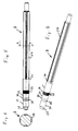
- FIGS. 3 to 7 Based on FIGS. 3 to 7 the pump shaft 9 and its connection with the motor shaft 7 is shown in detail.
- the motor shaft For receiving the motor-side end of the pump shaft 7, the motor shaft at its pump-side end of a blind hole 24.
- This blind hole 24 is stepped and has near its bottom a cylindrical portion which is intended to receive a guide pin 25 which is arranged at the motor end of the pump shaft 9.
- This guide pin 25 is in the installed position ( Fig. 3
- a contrast expanded section 26 in the blind hole which is provided with an internal thread, which is provided for receiving an external thread 27 of the pump shaft 9 and determined.
- a cylindrical portion 28 connects, which is continued to the pump end of the motor shaft 7.
- the shaft continues with substantially the same cylindrical outer circumference up to a transition region 36, in which it merges into a tapered shaft section 37 tapered.
- a stop ring 38 which forms an axial abutment for the wheels 10, which are rotationally fixed by means of the spline profile held on the spline shaft portion 37 and the ends are braced by a nut 39.
- Fig. 3 can be seen sitting in the installed position of the cylindrical portion 30 of the pump shaft 9, which forms a transition fit with the cylindrical portion 28 of the blind hole 24, centrally in the region of the motor shaft 7, which carries the ball bearing 11.
- the cylindrical portion 33 which forms an interference fit with the cylindrical portion 28 of the blind hole 24, located in the region of the blind hole, which is arranged at a distance from the ball bearing 11.
- the connection of the shafts 7 and 9 thus takes place in two fits, namely a transition fit 31 in the bearing area and a press fit 34 near the end of the motor shaft 7.
- the area between the cylindrical portion 33 and the transition area 36 serves to receive the mechanical seal 15.
- the pump shaft 9, as described above and shown in the drawing, can be attached to the assembled motor 1, without unduly burdening it.
- the joining forces directed in the axial direction of the shafts 7, 9 for joining the transition fit 31 and the interference fit 34 are applied by a torque which is applied between the motor shaft 7 and the pump shaft 9.
- corresponding positive locking means are provided on these shafts 7, 9.
- the shafts 7 and 9 are initially moved axially toward each other until the guide pin 25 is completely within the threaded portion 26. Then, the torque is introduced, which ensures that the external thread 27 of the shaft 9 rotates into the threaded portion 26 of the blind hole 24 of the motor shaft 7. According to the thread pitch, the shafts 7, 9 are moved axially toward each other.
Abstract
Description
Die Erfindung betrifft ein mehrstufiges Kreiselpumpenaggregat mit den im Oberbegriff des Anspruchs 1 angegebenen Merkmalen.The invention relates to a multi-stage centrifugal pump unit with the features specified in the preamble of claim 1.
Mehrstufige Kreiselpumpenaggregate dieser Art zählen in unterschiedlichsten Ausführungen zum Stand der Technik. Es wird in diesem Zusammenhang nur beispielhaft auf die von der Firma Grundfos unter der Typenbezeichnung CH bzw. CHN hergestellten und vertriebenen Aggregate verwiesen, zum Beispiel das Aggregat des Typs CHN2-50 mit Antriebsmotor MG71. Es handelt sich bei diesen mehrstufigen Kreiselpumpenaggregaten insbesondere um solche, deren Welle liegend angeordnet ist, das heißt bei üblicher Ausrichtung horizontal.Multistage centrifugal pump units of this type are state of the art in a wide variety of designs. In this connection, reference is made, by way of example only, to the units manufactured and sold by Grundfos under the type designation CH or CHN, for example the CHN2-50 unit with MG71 drive motor. These multistage centrifugal pump units are in particular those whose shaft is arranged horizontally, that is to say horizontal in the usual orientation.
Die Pumpenaggregate der vorgenannten Baureihe haben sich im praktischen Einsatz bestens bewährt. Sie weisen ein Motorgehäuse mit einer darin drehbar gelagerten Motorwelle auf, die einen Rotor trägt, sowie ein Pumpengehäuse mit einer drehbar gelagerten Pumpenwelle, auf welche mehrere Laufräder drehfest angeordnet sind. Das Motorgehäuse ist fest mit dem Pumpengehäuse verbunden und weist typischerweise ein gemeinsames Bauteil auf, den Lagerträger, der das pumpenseitige Ende der Motorwelle und das in diesem Bereich eingegliederte motorseitige Ende der Pumpenwelle radial abstützt. Dabei ist das motorseitige Ende der Pumpenwelle innerhalb eines Sacklochs am pumpenseitigen Ende der Motorwelle festgelegt, und zwar durch eine Presspassung, die üblicherweise durch thermisches Fügen, das heißt durch Fügen nach Erwärmen der Motorwelle und Abkühlen der Pumpenwelle und/oder durch Aufbringen entsprechend hoher Kräfte in Achsrichtung der Wellen erfolgt. Dies ist grundsätzlich unproblematisch, hat jedoch den Nachteil, dass die Wellenverbindung typischerweise vor Fertigmontage des Motors erfolgen muss, da die gesonderte Erwärmung der Motorwelle sonst nicht möglich ist. Im Übrigen ist der Motor für die Aufbringung derart hoher axialer Kräfte, wie sie zum Fügen einer Presspassung erforderlich sind, üblicherweise nicht ausgelegt. Es muss also bei der Motorfertigung bereits festgelegt werden, welche Pumpe, das heißt welche Welle für welche Anzahl von Laufrädern zum Einsatz kommt. Darüber hinaus ist die axiale Baulänge dieser bekannten Konstruktion im Bereich Lager/Wellenverbindung vergleichsweise groß, da die Presspassung außerhalb des Lagerbereichs angeordnet ist, um diesen nicht negativ zu beeinflussen.The pump units of the aforementioned series have proven their worth in practical use. They have a motor housing with a rotatably mounted therein motor shaft, which carries a rotor, and a pump housing with a rotatably mounted pump shaft, on which a plurality of wheels are arranged rotationally fixed. The motor housing is fixedly connected to the pump housing and typically has a common component, the bearing carrier, which radially supports the pump-side end of the motor shaft and the motor-side end of the pump shaft incorporated in this region. In this case, the motor-side end of the pump shaft is fixed within a blind hole at the pump end of the motor shaft, by a press fit, usually by thermal joining, that is by joining after heating the motor shaft and cooling the pump shaft and / or by applying correspondingly high forces in Axial direction of the waves takes place. This is basically unproblematic, but has the disadvantage that the shaft connection typically has to be done before final assembly of the engine, since the separate heating of the motor shaft is otherwise not possible. Incidentally, the motor for the application of such high axial forces, as required for joining a press fit, usually not designed. It must therefore already be determined in the engine manufacturing, which pump, that is, which shaft is used for which number of wheels. In addition, the axial length of this known construction in the area bearing / shaft connection is comparatively large, since the interference fit is arranged outside the storage area in order not to adversely affect this.
Vor diesem Hintergrund liegt der Erfindung die Aufgabe zu Grunde, ein gattungsgemäßes mehrstufiges Kreiselpumpenaggregat so auszubilden, dass die Verbindung zwischen Motorwelle und Pumpenwelle auch nach Montage des Motors erfolgen kann und die darüber hinaus eine in Axialrichtung kompakt bauende Konstruktion ermöglicht.Against this background, the invention is based on the object, a generic multi-stage centrifugal pump unit in such a way that the connection between the motor shaft and pump shaft can also be done after mounting the motor and also allows a compact design in the axial direction.
Diese Aufgabe wird gemäß der Erfindung durch ein Kreiselpumpenaggregat mit den im Anspruch 1 angegebenen Merkmalen gelöst. Vorteilhafte Ausgestaltungen der Erfindung sind in den Unteransprüchen, der nachfolgenden Beschreibung und der Zeichnung angegeben.This object is achieved according to the invention by a centrifugal pump unit having the features specified in claim 1. Advantageous embodiments of the invention are specified in the subclaims, the following description and the drawing.
Bei dem erfindungsgemäßen Kreiselpumpenaggregat ist die Pumpenwelle an oder nahe ihrem motorseitigen Ende mit einem Außengewinde versehen, das in ein Innengewinde des Sacklochs am pumpenseitigen Ende der Motorwelle eingreift. Mit Abstand in Richtung zum Laufrad davon ist eine erste Passung sowie davon beabstandet eine zweite Passung zwischen Pumpenwelle und Sackloch vorgesehen. Durch die Gewindeverbindung zwischen den beiden Wellen ist eine Fügung der Passungen auch nach Montage des Motors möglich, da bei Anbringung geeigneter Formschlussmittel auf den zu verbindenden Wellen, die Axialkräfte ausschließlich durch das Fügen der Gewindeabschnitte zwischen Pumpenwelle und Motorwelle aufgebracht werden, also keinerlei axiale Belastung des Motors erfolgt. Durch die Teilung der Passung in zwei voneinander beabstandete Teilpassungen kann zudem sichergestellt werden, dass etwaige Materialaufweitungen der Motorwelle in Bereiche außerhalb des Lagers gelegt werden können. Darüber hinaus sind die Spannungsverteilungen innerhalb der Wellen aufgrund der zwei voneinander beabstandeten Passungen wesentlich günstiger als bei einer einzigen Passung, die eine größere Länge aufweisen muss. Schließlich kann durch diese Aufteilung zumindest eine Passung in den Bereich des Lagers gelegt werden, wodurch die axiale Baulänge verringert werden kann.In the centrifugal pump unit according to the invention, the pump shaft is provided at or near its motor end with an external thread which engages in an internal thread of the blind hole at the pump end of the motor shaft. At a distance in the direction of the impeller thereof, a first fit and, spaced therefrom, a second fit between the pump shaft and the blind hole are provided. Due to the threaded connection between the two shafts, it is possible to add the fits even after the motor has been mounted, as when mounting suitable positive engagement means on the shafts to be connected, the axial forces are applied exclusively by the joining of the threaded portions between the pump shaft and motor shaft, so no axial load on the motor takes place. By dividing the fit into two spaced-apart partial fits can also be ensured that any material widening of the motor shaft can be placed in areas outside the camp. Moreover, due to the two spaced fits, the stress distributions within the shafts are much less expensive than with a single fit, which must be longer in length. Finally, by this division, at least one fit can be placed in the region of the bearing, whereby the axial length can be reduced.
Grundgedanke der vorliegenden Erfindung ist es also, die Konstruktion der Wellenverbindung so auszulegen, dass die vergleichsweise hohen Fügekräfte in Achsrichtung beim Fügen der Presspassung, welche den Motor nach erfolgter Montage unzulässig belasten würden, durch innere Kräfte aufzubringen, nämlich durch die beim Fügen des Gewindes entstehenden Zugkräfte, die durch entsprechendes Aufbringen eines Drehmoments zwischen den Wellen entstehen. Ein weiterer wesentlicher Gedanke ist die sonst übliche, eine Presspassung durch zwei voneinander beabstandete Passungen zu ersetzen, die dann naturgemäß axial kürzer ausgestaltet sein können und an geeigneter Stelle angeordnet werden können, ohne dass hierfür gesonderte Wellenabschnitte vorzusehen sind, die sonst ohne konstruktive Funktion sind.The basic idea of the present invention is therefore to design the construction of the shaft connection in such a way that the comparatively high joining forces in the axial direction during joining of the interference fit, which would unduly burden the motor after assembly, are applied by internal forces, namely by the forces arising during the joining of the thread Tensile forces caused by corresponding application of torque between the shafts. Another essential idea is the usual, to replace a press fit by two spaced apart fits, which can then be designed axially shorter and naturally can be arranged at a suitable location without the need for separate shaft sections are provided, which are otherwise without constructive function.
Besonders vorteilhaft ist es, wenn gemäß einer Weiterbildung der Erfindung die erste Passung eine Übergangspassung ist. Erste Passung im Sinne der vorliegenden Erfindung ist die, die dem Motor am nächsten ist. Um die erforderlichen Kräfte übertragen zu können, ist dann vorteilhaft die zweite Passung eine Presspassung. Diese Abstufung in Übergangs- und Presspassung ist besonders vorteilhaft, da innerhalb des Sacklochs der Motorwelle die aufgrund der Passungen entstehenden Spannungen so abgestuft aufgebracht werden, dass sie am Ende der Motorwelle am höchsten sind und nicht in einem mittleren, insbesondere Lagerbereich.It is particularly advantageous if, according to an embodiment of the invention, the first fit is a transition fit. The first fit in the sense of the present invention is that which is closest to the engine. In order to transfer the required forces, then advantageously the second fit is an interference fit. This grading in transitional and press-fitting is particularly advantageous because within the blind hole of the motor shaft, the resulting stresses due to the fits are applied stepped so that they are highest at the end of the motor shaft and not in a middle, especially storage area.
Zweckmäßigerweise ist am motorseitigen Ende der Pumpenwelle ein Führungszapfen vorgesehen, der mit Spiel in einer entsprechend am Boden des Sacklochs ausgebildeten Ausnehmung sitzt. Ein solcher Führungszapfen sorgt für eine sichere Führung beim Fügen der Wellen und verhindert eine Beschädigung des Gewindes, wenn die Wellen ineinander gesteckt werden, bevor die Verschraubung erfolgt.Appropriately, a guide pin is provided at the motor end of the pump shaft, which sits with play in a correspondingly formed at the bottom of the blind hole recess. Such a guide pin provides a safe guide when joining the shafts and prevents damage to the thread when the shafts are inserted into each other before the screw connection.
Für den Fügevorgang vorteilhaft ist es weiterhin, dass die Pumpenwelle von ihrem motorseitigen Außengewinde zu dem Abschnitt hin, welcher Teil der ersten Passung bildet, konisch aufweitend ausgebildet ist. Hierdurch erfolgt eine selbsttätige Zentrierung während des Fügevorgangs, sodass sich die Kräfte über den gesamten Umfang gleichmäßig verteilen können.It is also advantageous for the joining process that the pump shaft is designed to widen conically from its motor-side external thread to the section which forms part of the first fit. This results in an automatic centering during the joining process, so that the forces can be distributed evenly over the entire circumference.
Besonders vorteilhaft ist es, wenn die Pumpenwelle im Bereich zwischen den Abschnitten für die erste und die zweite Passung einen geringeren Durchmesser als in den Passungsabschnitten aufweist. Auch dies unterstützt den Fügevorgang günstig insbesondere dann, wenn beide Passungen etwa den gleichen Nenndurchmesser aufweisen.It is particularly advantageous if the pump shaft has a smaller diameter in the region between the sections for the first and the second fitting than in the fitting sections. This also supports the joining process in particular when both fits have approximately the same nominal diameter.
Um die Fügekräfte insbesondere für die zweite Passung, die vorteilhaft als Presspassung ausgebildet ist, in definierten Grenzen zu halten, ist gemäß einer Weiterbildung der Erfindung vorgesehen, die zweite Passung mit umlaufenden Schmiernuten zu versehen, welche den Fügevorgang insbesondere im Bereich der Presspassung erleichtern. Die Schmiernuten werden vor dem Fügen mit einem geeigneten Gleitmittel gefüllt und verhindern insbesondere die Gefahr von Kaltverschweißungen, wie sie beim Fügen unter hohen Kräften insbesondere bei Edelstählen gelegentlich auftreten.In order to keep the joining forces, in particular for the second fit, which is advantageously designed as a press fit within defined limits, is provided according to a development of the invention to provide the second fit with circumferential lubrication, which facilitate the joining process, especially in the field of interference fit. The lubrication grooves are filled with a suitable lubricant before joining filled and prevent in particular the risk of cold welding, as they occasionally occur during joining under high forces, especially in stainless steels.
Die erste Passung, die bevorzugt eine Übergangspassung ist, wird gemäß einer Weiterbildung der Erfindung zweckmäßigerweise dort angeordnet, wo die Motorwelle vom Lager umgeben ist, und zwar vorzugsweise mittig zum Lager, also dort wo sich die Wälzkörper abstützen, wenn ein solches Wälzlager eingesetzt wird, was in diesem Bereich üblich ist.The first fit, which is preferably a transition fit, is expediently arranged according to an embodiment of the invention where the motor shaft is surrounded by the bearing, preferably centrally to the bearing, ie where the rolling elements are supported when such a rolling bearing is used, which is common in this area.
Die zweite Passung, bei der es sich vorzugsweise um die Presspassung handelt, ist vorteilhaft jenseits des Lagers, und zwar zur Pumpenseite hin nahe dem Ende der Motorwelle angeordnet. Diese Anordnung hat den Vorteil, dass aufgrund der Presspassung keine Einwirkungen auf das Lager zu befürchten sind und andererseits die Verbindung so weit wie möglich pumpenseitig angeordnet ist, was sowohl im Hinblick auf die Lagerung der Motorwelle als auch insbesondere im Hinblick auf die sich ergebenden Momentenbelastungen der Pumpenwelle im Hinblick auf die Lagerung und die Passungsverbindung selbst besonders günstig ist.The second fit, which is preferably the interference fit, is advantageously located beyond the bearing, near the end of the motor shaft, toward the pump side. This arrangement has the advantage that due to the interference fit no effects on the bearing are to be feared and on the other hand, the connection is arranged as far as possible pump side, which both in terms of the bearing of the motor shaft and in particular with regard to the resulting moment loads of Pump shaft is particularly favorable in terms of storage and the fit connection itself.
Um zuverlässig zu verhindern, dass etwaige Förderflüssigkeit, die längs der Pumpenwelle über die Gleitringdichtung aus dem Pumpengehäuse austritt, über die Motorwelle in den Motor gelangt, ist gemäß einer Weiterbildung der Erfindung vor dem pumpenseitigen Ende der Motorwelle auf der Pumpenwelle ein Schleuderring angeordnet, der die Pumpenwelle dicht umgreift und innerhalb eines Freiraums des Lagerträgers angeordnet ist, der über einen unten anschließenden Kanal mit der Umgebung leitungsverbunden ist. Unten im Sinne der Erfindung bedeutet in Einbaulage, also dort, wo die Flüssigkeit schwerkraftbedingt natürlich abfließt. Durch einen solchen Schleuderring wird etwaige längs der Welle langlaufende Flüssigkeit auf den Schleuderring geleitet, der bei Drehung der Welle aufgrund der Zentrifugalkraft die Flüssigkeit nach außen leitet, wo sie dann schwerkraftbedingt über den Freiraum und den Kanal abgeführt wird.In order to reliably prevent any conveying liquid which emerges from the pump housing via the mechanical seal along the pump shaft, enters the motor via the motor shaft, according to a development of the invention a centrifugal ring is arranged on the pump shaft in front of the pump end of the motor shaft Pump shaft tightly engages and is disposed within a free space of the bearing carrier, which is conductively connected to the environment via a subsequent downstream channel. Below in the sense of the invention means in installation position, ie where the liquid flows naturally due to gravity. By such a slinger any long-running liquid along the shaft is passed to the slinger, which at Rotation of the shaft due to the centrifugal force, the liquid passes outwards, where it is then discharged by gravity through the space and the channel.
Gemäß einer Weiterbildung der Erfindung weist der Schleuderring einen h-förmigen Querschnitt auf und ist mittels eines am pumpenseitigen Ende der Motorwelle gebildeten Wulstes formschlüssig rastend gehalten. Ein solcher Wulst kann in einfacher Weise durch Einstechen einer Nut im Endbereich der Motorwelle gebildet werden. Der elastische Schleuderring wird über den Wulst gestülpt und verrastet dann innerhalb der Nut, durch die er dann in axialer Richtung fixiert ist, wohingegen seine dichtende Anlage mit dem anderen Schenkel an der Pumpenwelle erfolgt. Hierzu ist der Schleuderring aus einem elastischen Material auszubilden, vorteilhaft aus Kunststoff. Die Anordnung gegenüber der Pumpenwelle ist so, dass dieser vorgespannt ist, sodass auch über lange Zeit eine dichte Anlage an der Pumpenwelle gewährleistet ist.According to one embodiment of the invention, the slinger on an H-shaped cross-section and is held by means of a formed on the pump-side end of the motor shaft bead positively locking. Such a bead can be formed in a simple manner by piercing a groove in the end region of the motor shaft. The elastic slinger is slipped over the bead and then locked within the groove, through which it is then fixed in the axial direction, whereas its sealing engagement with the other leg takes place on the pump shaft. For this purpose, the slinger is made of an elastic material, preferably made of plastic. The arrangement with respect to the pump shaft is such that it is prestressed so that a tight contact with the pump shaft is ensured over a long period of time.
Um weitere Sicherheit gegen eindringende Flüssigkeit in den Motor zu gewährleisten, ist gemäß einer Weiterbildung der Erfindung im Lagerträger zwischen Lager und Schleuderring ein feststehender Dichtring vorgesehen, der radial gegenüber dem Lagerträger mittels eines O-Rings abgedichtet ist und der vorgespannt dichtend an der axialen Seite des mit der Welle mitdrehenden inneren Lagerrings des Wälzlagers läuft, und zwar auf der der Pumpe zugewandten Seite. Da der Lagerring eines Wälzlagers typischerweise oberflächenbearbeitet ausgebildet ist, bietet sich diese Fläche zur Bildung einer zusätzlichen Dichtfläche an, da herstellerseitig keine gesonderte weitere Bearbeitung erforderlich ist. Um etwaige in diesen Bereich gelangende Flüssigkeit abzuführen ist auch dieser feststehende Dichtring vorteilhaft innerhalb eines Freiraums angeordnet, der mit der Umgebung leitungsverbunden ist, zweckmäßigerweise über den selben Kanal, über den auch der Schleuderring mit der Umgebung, also mit der das Pumpenaggregat umgebenden Umgebung verbunden ist.In order to ensure further safety against penetrating liquid in the engine, a fixed sealing ring is provided according to a development of the invention in the bearing carrier between the bearing and the slinger, which is sealed radially relative to the bearing carrier by means of an O-ring and the biased sealing on the axial side of the running with the shaft co-rotating inner bearing ring of the bearing, on the side facing the pump. Since the bearing ring of a roller bearing is typically surface-finished, this surface offers the formation of an additional sealing surface, since the manufacturer no separate further processing is required. To dissipate any reaching into this area liquid and this fixed sealing ring is advantageously disposed within a free space, which is conductively connected to the environment, advantageously via the same channel, via which also the Slinger is connected to the environment, so with the environment surrounding the pump unit environment.
Die Erfindung ist nachfolgend anhand eines in der Zeichnung dargestellten Ausführungsbeispiels näher erläutert. Es zeigen:
- Fig. 1
- in stark vereinfachter, schematischer Darstellung einen Längs- schnitt durch ein dreistufiges Pumpenaggregat gemäß der Erfin- dung,
- Fig. 2
- in vergrößerter Schnittdarstellung den Bereich des Lagerträgers der
Fig. 1 , - Fig. 3
- in stark vereinfachter, schematischer Schnittdarstellung ein La- ger, ein pumpenseitiges Ende der Motorwelle und ein motorseiti- ges Ende der Pumpenwelle,
- Fig. 4
- den motorseitigen Teil der Pumpenwelle im Längsschnitt,
- Fig. 5
- die Pumpenwelle in Seitenansicht,
- Fig. 6
- einen Schnitt längs der Schnittlinie A - A in
Fig. 5 und - Fig. 7
- eine perspektivische Darstellung der Pumpenwelle.
- Fig. 1
- in a highly simplified, schematic representation a longitudinal section through a three-stage pump unit according to the invention,
- Fig. 2
- in an enlarged sectional view of the area of the bearing carrier of
Fig. 1 . - Fig. 3
- in a simplified, schematic sectional representation a bearing, a pump-side end of the motor shaft and a motor-side end of the pump shaft,
- Fig. 4
- the motor-side part of the pump shaft in longitudinal section,
- Fig. 5
- the pump shaft in side view,
- Fig. 6
- a section along the section line A - A in
Fig. 5 and - Fig. 7
- a perspective view of the pump shaft.
Das anhand der Figuren dargestellte Pumpenaggregat weist einen Motor 1 mit einem Motorgehäuse 2 und eine Pumpe 3 mit einem Pumpengehäuse 4 auf. Motorgehäuse 2 und Pumpengehäuse 4 sind über einen Lagerträger 5 miteinander verbunden. Der Lagerträger 5 kann je nach Ausführung Teil des Motorgehäuses 2 oder Teil des Pumpengehäuses 4 oder Teil von beiden bilden.The pump unit illustrated with reference to the figures has a motor 1 with a
Innerhalb des Motorgehäuses 2 ist eine einen Rotor 6 tragende Motorwelle 7 angeordnet, an deren einem Ende ein Lüfterrad 8 befestigt ist und an deren anderem Ende eine Pumpenwelle 9 anschließt, die innerhalb des Pumpengehäuses 4 gelagert ist und die in der dargestellten Ausführungsform drei Laufräder 10 trägt. Die Motorwelle 7 ist pumpenseitig, also dort, wo die Pumpenwelle 9 mit der Motorwelle 7 drehfest verbunden ist, mittels eines Wälzlagers 11 in Form eines Kugellagers gelagert, das im Lagerträger 5 angeordnet ist.Inside the
An der freien Stirnseite des Pumpengehäuses 4 ist ein Sauganschluss 12 der Pumpe vorgesehen, der koaxial zur Drehachse 13 der Wellen 7 und 9 angeordnet ist. Die Pumpe 3 weist einen Druckanschluss 14 auf, der radial nach oben abgeht und mit dem Ausgang der dritten Pumpenstufe leitend verbunden ist. Am motorseitigen Ende des Pumpengehäuses 4 ist eine Gleitringdichtung 15 vorgesehen. Weitere Dichtmittel sind im Bereich des Lagerträgers 5 vorgesehen.At the free end face of the pump housing 4, a
So ist ein im Querschnitt h-förmiger Schleuderring 16 am motorseitigen Ende der Pumpenwelle 9 dichtend angebracht. Der Schleuderring 16 ist aus elastischem Kunststoffmaterial gebildet und übergreift einen endseitigen Wulst 17, der durch eine Nut 18 nahe dem pumpenseitigen Ende in der Motorwelle 7 gebildet ist. Der Schleuderring 16 ist über den Wulst 17 übergestülpt und somit formschlüssig rastend mit dem kurzen Schenkel seines Querschnitts in der Nut 18 angeordnet. Der lange Schenkel liegt mit seiner Innenseite dichtend an der Pumpenwelle 9 an. Der Innenbereich ist im Bereich des langen Schenkels, also dort, wo er zur Pumpe gerichtet ist, vorgespannt, sodass er dichtend an der Pumpenwelle 9 anliegt. Er liegt innerhalb eines Freiraums 19 des Lagerträgers 5, der über einen nach unten führenden Kanal 20 mit der Außenumgebung verbunden ist. Im Betrieb gelangt etwaige längs der Pumpenwelle 9 durch die Gleitringdichtung 15 dringende Flüssigkeit auf den Schleuderring 16, der diese mitnimmt und durch Zentrifugalkraft in den Freiraum 19 schleudert, von wo sie über den Kanal 20 nach außen abgeführt wird.Thus, a h-shaped in
In Richtung zum Motor 1 ist hinter dem Freiraum 19 ein weiterer Freiraum 21 geringeren Durchmessers angeordnet, der mit dem Freiraum 19 verbunden ist und der zur Aufnahme eines feststehenden Dichtrings 22 vorgesehen ist, der innerhalb der radialen Umfangsfläche des Freiraums 21 festgelegt ist und mittels eines O-Rings 23 gegenüber dem Lagerträger 5 abgedichtet ist. Dieser feststehende Dichtring 22 weist einen radial nach innen gerichteten Abschnitt auf, mit dem dieser an der axialen Seite des mit der Welle 7 mitdrehenden inneren Lagerrings des Kugellagers 11 anliegt und somit eine weitere Barriere gegen Flüssigkeit bildet.In the direction of the engine 1, a further free space 21 of smaller diameter is arranged behind the
Anhand der
Wellenseitig schließt sich in Richtung der Laufräder 10 gesehen an den mit Außengewinde 27 versehenen Abschnitt ein sich konisch aufweitender Abschnitt 29 an, der in einen zylindrischen Abschnitt 30 übergeht, der Teil einer ersten Passung 31 bildet. An diesen zylindrischen Teil 30 schließt sich ein ebenfalls zylindrischer Abschnitt 32 an, der jedoch gegenüber dem zylindrischen Teil 30 abgesetzt ausgebildet ist, also einen kleineren Durchmesser aufweist. An den zylindrischen Abschnitt 32 schließt sich ein weiterer zylindrischer Abschnitt 33 an, der Teil einer zweiten Passung 34 bildet. Dieser zylindrische Abschnitt 33 weist einen größeren Durchmesser als der zylindrische Teil 30 der ersten Passung auf. Er ist darüber hinaus mit mehreren umlaufenden Nuten 35 versehen, welche Schmiernuten bilden. Von da an setzt sich die Welle mit im Wesentlichen gleichem zylindrischen Außenumfang fort bis zu einem Übergangsbereich 36, in dem sie konisch zulaufend in einen Keilwellenabschnitt 37 übergeht. In diesem Übergangsbereich sitzt ein Anschlagring 38, der ein axiales Widerlager für die Laufräder 10 bildet, die mittels des Keilwellenprofils drehfest auf dem Keilwellenabschnitt 37 gehalten sind und endseitig mittels einer Mutter 39 verspannt sind.On the shaft side, as viewed in the direction of the
Wie insbesondere aus
Der Bereich zwischen dem zylindrischen Abschnitt 33 und dem Übergangsbereich 36 dient zur Aufnahme der Gleitringdichtung 15.The area between the
Die Pumpenwelle 9, wie sie vorstehend beschrieben und in der Zeichnung dargestellt ist, kann am fertig montierten Motor 1 befestigt werden, ohne diesen unzulässig zu belasten. Die in Achsrichtung der Wellen 7, 9 gerichteten Fügekräfte zum Fügen der Übergangspassung 31 sowie der Presspassung 34 werden durch ein Drehmoment aufgebracht, welches zwischen der Motorwelle 7 und der Pumpenwelle 9 aufgebracht wird. Hierzu sind an diesen Wellen 7, 9 entsprechende Formschlussmittel vorgesehen. Die Wellen 7 und 9 werden zunächst axial aufeinander zu bewegt, bis der Führungszapfen 25 vollständig innerhalb des Gewindeabschnitts 26 liegt. Sodann wird das Drehmoment eingeleitet, welches dafür sorgt, dass sich das Außengewinde 27 der Welle 9 in den Gewindeabschnitt 26 des Sacklochs 24 der Motorwelle 7 eindreht. Entsprechend der Gewindesteigung werden die Wellen 7, 9 axial aufeinander zu bewegt. Dabei werden schließlich die zylindrischen Abschnitte 30 und 33 in den Bereich der Passungen 31 und 34 bewegt. Die größten Kräfte entstehen dabei im Bereich der Presspassung 34. Um diese in zulässigen Grenzen zu halten, sind die Schmiernuten 35 vorgesehen. Die bestimmungsgemäße Position ist erreicht, sobald der Führungszapfen 25 am Boden der Sacklochbohrung 24 anschlägt. Es wird dann zunächst das sich an den Lagerträger 5 anschließende Pumpengehäuseteil montiert, wonach die Gleitringdichtung 15, dann der Anschlagring 38 sowie die Laufräder montiert werden. Die weitere Montage der Pumpe erfolgt in üblicher Weise.The
- 11
- Motorengine
- 22
- Motorgehäusemotor housing
- 33
- Pumpepump
- 44
- Pumpengehäusepump housing
- 55
- Lagerträgerbearing bracket
- 66
- Rotorrotor
- 77
- Motorwellemotor shaft
- 88th
- Lüfterradfan
- 99
- Pumpenwellepump shaft
- 1010
- Laufräderimpellers
- 1111
- Kugellagerball-bearing
- 1212
- Sauganschlusssuction
- 1313
- Drehachseaxis of rotation
- 1414
- Druckanschlusspressure connection
- 1515
- GleitringdichtungMechanical seal
- 1616
- Schleuderringslinger
- 1717
- Wulstbead
- 1818
- Nutgroove
- 1919
- Freiraumfree space
- 2020
- Kanalchannel
- 2121
- Freiraumfree space
- 2222
- feststehender Dichtringfixed sealing ring
- 2323
- O-RingO-ring
- 2424
- Sacklochblind
- 2525
- Führungszapfenspigot
- 2626
- Gewindeabschnitt von 24Thread section of 24
- 2727
- Außengewinde von 9External thread of 9
- 2828
- Zylindrischer Abschnitt von 24Cylindrical section of 24
- 2929
- konisch aufweitender Abschnitt von 9conically widening section of 9
- 3030
- zylindrischer Teil von 9cylindrical part of 9
- 3131
- erste Passung, Überganspassungfirst fit, over-fitting
- 3232
- zylindrischer Abschnitt von 9cylindrical section of 9
- 3333
- zylindrischer Abschnitt von 9cylindrical section of 9
- 3434
- zweite Passung, Presspassungsecond fit, press fit
- 3535
- Schmiernutenlubrication
- 3636
- Übergangsbereich von 9Transitional area of 9
- 3737
- Keilwellenabschnitt von 9Spline shaft section of 9
- 3838
- Anschlagringstop ring
- 3939
- Muttermother
Claims (14)
Priority Applications (5)
| Application Number | Priority Date | Filing Date | Title |
|---|---|---|---|
| EP09003441.4A EP2233747B1 (en) | 2009-03-10 | 2009-03-10 | Multi stage motor pump unit |
| PL09003441T PL2233747T3 (en) | 2009-03-10 | 2009-03-10 | Multi stage motor pump unit |
| TW098121125A TWI476325B (en) | 2009-03-10 | 2009-06-24 | Multi-stage centrifugal pump assembly |
| US12/720,792 US8376701B2 (en) | 2009-03-10 | 2010-03-10 | Multi-stage centrifugal pump assembly (shaft) |
| CN2010101356123A CN101832271B (en) | 2009-03-10 | 2010-03-10 | Multi-stage centrifugal pump assembly |
Applications Claiming Priority (1)
| Application Number | Priority Date | Filing Date | Title |
|---|---|---|---|
| EP09003441.4A EP2233747B1 (en) | 2009-03-10 | 2009-03-10 | Multi stage motor pump unit |
Publications (2)
| Publication Number | Publication Date |
|---|---|
| EP2233747A1 true EP2233747A1 (en) | 2010-09-29 |
| EP2233747B1 EP2233747B1 (en) | 2017-09-13 |
Family
ID=40887100
Family Applications (1)
| Application Number | Title | Priority Date | Filing Date |
|---|---|---|---|
| EP09003441.4A Active EP2233747B1 (en) | 2009-03-10 | 2009-03-10 | Multi stage motor pump unit |
Country Status (5)
| Country | Link |
|---|---|
| US (1) | US8376701B2 (en) |
| EP (1) | EP2233747B1 (en) |
| CN (1) | CN101832271B (en) |
| PL (1) | PL2233747T3 (en) |
| TW (1) | TWI476325B (en) |
Families Citing this family (7)
| Publication number | Priority date | Publication date | Assignee | Title |
|---|---|---|---|---|
| CN103742438B (en) * | 2013-12-26 | 2016-06-22 | 大连深蓝泵业有限公司 | Centrifugal multistage pump multiple centrifugal pump rotating-shaft support devices |
| WO2015148647A1 (en) * | 2014-03-25 | 2015-10-01 | Trane International Inc. | Methods and systems to mount a rotor to a shaft |
| WO2017114402A1 (en) * | 2015-12-30 | 2017-07-06 | 余炳炎 | Cross-flow flow-making water pump |
| CN105673548A (en) * | 2016-03-17 | 2016-06-15 | 高碑店市万盛源风机配件加工厂 | Highly-seal fan transmission shaft and fan transmission system |
| CN107061347B (en) * | 2017-04-07 | 2023-05-12 | 兰州兰泵有限公司 | Impeller connecting structure of multistage centrifugal pump and quick assembling and disassembling method thereof |
| EP4198319A1 (en) | 2021-12-17 | 2023-06-21 | Grundfos Holding A/S | Pump assembly |
| CN115041924B (en) * | 2022-06-28 | 2024-01-23 | 山东省章丘鼓风机股份有限公司 | Multistage centrifugal fan shell processing method |
Citations (5)
| Publication number | Priority date | Publication date | Assignee | Title |
|---|---|---|---|---|
| FR2288888A2 (en) * | 1974-04-26 | 1976-05-21 | Seplec Ste Nouvelle Moteurs | Pump and electric motor unit - has impeller hub with washer and thrower protecting shaft hermetically |
| DE4223544A1 (en) * | 1992-07-17 | 1994-01-20 | Kaco Gmbh Co | Water pump for vehicle IC engine - has bearing lubricant chamber formed between two shaft seals |
| DE29606135U1 (en) * | 1996-04-02 | 1996-08-22 | Speck Pumpenfabrik Walter Spec | Galvanically isolated pump |
| DE10323169A1 (en) * | 2003-05-22 | 2004-12-09 | Ina-Schaeffler Kg | Device for connecting machine parts especially for motor vehicle steering and track rods has adhesive or pressed solder to bind a threaded boring and plug |
| DE102006021446A1 (en) * | 2006-05-09 | 2007-11-15 | Schaeffler Kg | Shaft of a water pump of an internal combustion engine |
Family Cites Families (3)
| Publication number | Priority date | Publication date | Assignee | Title |
|---|---|---|---|---|
| US4986733A (en) * | 1989-10-30 | 1991-01-22 | Allied-Signal, Inc. | Turbocharger compressor wheel assembly with boreless hub compressor wheel |
| US5378124A (en) * | 1993-06-07 | 1995-01-03 | Maytag Corporation | Method and means for assembling a pump and motor |
| JP4293217B2 (en) * | 2006-09-22 | 2009-07-08 | パナソニック電工株式会社 | Pump and fluid supply device |
-
2009
- 2009-03-10 EP EP09003441.4A patent/EP2233747B1/en active Active
- 2009-03-10 PL PL09003441T patent/PL2233747T3/en unknown
- 2009-06-24 TW TW098121125A patent/TWI476325B/en active
-
2010
- 2010-03-10 US US12/720,792 patent/US8376701B2/en active Active
- 2010-03-10 CN CN2010101356123A patent/CN101832271B/en active Active
Patent Citations (5)
| Publication number | Priority date | Publication date | Assignee | Title |
|---|---|---|---|---|
| FR2288888A2 (en) * | 1974-04-26 | 1976-05-21 | Seplec Ste Nouvelle Moteurs | Pump and electric motor unit - has impeller hub with washer and thrower protecting shaft hermetically |
| DE4223544A1 (en) * | 1992-07-17 | 1994-01-20 | Kaco Gmbh Co | Water pump for vehicle IC engine - has bearing lubricant chamber formed between two shaft seals |
| DE29606135U1 (en) * | 1996-04-02 | 1996-08-22 | Speck Pumpenfabrik Walter Spec | Galvanically isolated pump |
| DE10323169A1 (en) * | 2003-05-22 | 2004-12-09 | Ina-Schaeffler Kg | Device for connecting machine parts especially for motor vehicle steering and track rods has adhesive or pressed solder to bind a threaded boring and plug |
| DE102006021446A1 (en) * | 2006-05-09 | 2007-11-15 | Schaeffler Kg | Shaft of a water pump of an internal combustion engine |
Also Published As
| Publication number | Publication date |
|---|---|
| US20100232950A1 (en) | 2010-09-16 |
| US8376701B2 (en) | 2013-02-19 |
| PL2233747T3 (en) | 2018-03-30 |
| TW201033468A (en) | 2010-09-16 |
| EP2233747B1 (en) | 2017-09-13 |
| CN101832271B (en) | 2012-08-22 |
| TWI476325B (en) | 2015-03-11 |
| CN101832271A (en) | 2010-09-15 |
Similar Documents
| Publication | Publication Date | Title |
|---|---|---|
| EP2233747B1 (en) | Multi stage motor pump unit | |
| DE102013200488B4 (en) | Motor vehicle transmission | |
| EP0753678B1 (en) | Sliding-contact bearing for a shaft | |
| EP2047143A1 (en) | Pump drive of an automatic transmission | |
| WO2003093651A1 (en) | Device for fixing a rotor on a shaft | |
| EP1998009B1 (en) | Bearing device | |
| EP1744070B1 (en) | Thrust bearing | |
| EP2271852B1 (en) | Device for sealing a bearing lubricated with a liquid lubricant | |
| DE102010007668B4 (en) | Transmission element for a stress wave transmission, camshaft adjuster and power steering | |
| DE102009032294A1 (en) | bearing arrangement | |
| DE102004020851B4 (en) | Storage of a shaft | |
| DE19850920B4 (en) | Radial piston pump | |
| DE60208108T2 (en) | Assembly of two coaxial shafts | |
| EP1968871B1 (en) | Barrel motor | |
| DE202018107141U1 (en) | Rotary lobe pump with internal bearing | |
| DE102012202365A1 (en) | Mounting arrangement for pressing rolling bearing inner ring on conical bearing seat surface of shaft, has push plate engaged with inner ring, and bonnet wing nut whose ball screw thread shoots share same axis of rotation with wing nut | |
| EP2707629B1 (en) | Apparatus for sealing off a pump space of a rotary piston pump, and rotary piston pump having same | |
| DE102010035597A1 (en) | Bearing arrangement for a pump | |
| EP3196466B1 (en) | Displacement pump | |
| DE102005001839B4 (en) | Lubricating device for shaft-hub-connection in automobile engineering, has bearing inner ring forming nozzle-shaped cross-section together with shaft and/or hub for lubricating oil to axially feed oil into spline | |
| DE102017106942A1 (en) | Hydrodynamic coupling | |
| DE102017206240B3 (en) | Screw compressor assembly | |
| DE19906690B4 (en) | seal | |
| DE102006044637A1 (en) | Hinge bearing i.e. sliding bearing, has inner ring supported by clamping ring that is arranged at front side of inner ring, where clamping ring has rectangular cross section and is provided with chamfer, which is turned towards outer ring | |
| DE102018216910A1 (en) | Transmission gearbox for a vehicle with an electric machine |
Legal Events
| Date | Code | Title | Description |
|---|---|---|---|
| PUAI | Public reference made under article 153(3) epc to a published international application that has entered the european phase |
Free format text: ORIGINAL CODE: 0009012 |
|
| AK | Designated contracting states |
Kind code of ref document: A1 Designated state(s): AT BE BG CH CY CZ DE DK EE ES FI FR GB GR HR HU IE IS IT LI LT LU LV MC MK MT NL NO PL PT RO SE SI SK TR |
|
| AX | Request for extension of the european patent |
Extension state: AL BA RS |
|
| 17P | Request for examination filed |
Effective date: 20110129 |
|
| 17Q | First examination report despatched |
Effective date: 20110228 |
|
| AKX | Designation fees paid |
Designated state(s): AT BE BG CH CY CZ DE DK EE ES FI FR GB GR HR HU IE IS IT LI LT LU LV MC MK MT NL NO PL PT RO SE SI SK TR |
|
| GRAP | Despatch of communication of intention to grant a patent |
Free format text: ORIGINAL CODE: EPIDOSNIGR1 |
|
| INTG | Intention to grant announced |
Effective date: 20170405 |
|
| RAP1 | Party data changed (applicant data changed or rights of an application transferred) |
Owner name: GRUNDFOS MANAGEMENT A/S |
|
| RIN1 | Information on inventor provided before grant (corrected) |
Inventor name: SVENDSEN, KARL-HENRIK |
|
| GRAS | Grant fee paid |
Free format text: ORIGINAL CODE: EPIDOSNIGR3 |
|
| GRAA | (expected) grant |
Free format text: ORIGINAL CODE: 0009210 |
|
| AK | Designated contracting states |
Kind code of ref document: B1 Designated state(s): AT BE BG CH CY CZ DE DK EE ES FI FR GB GR HR HU IE IS IT LI LT LU LV MC MK MT NL NO PL PT RO SE SI SK TR |
|
| REG | Reference to a national code |
Ref country code: GB Ref legal event code: FG4D Free format text: NOT ENGLISH |
|
| REG | Reference to a national code |
Ref country code: CH Ref legal event code: EP |
|
| REG | Reference to a national code |
Ref country code: IE Ref legal event code: FG4D Free format text: LANGUAGE OF EP DOCUMENT: GERMAN |
|
| REG | Reference to a national code |
Ref country code: AT Ref legal event code: REF Ref document number: 928442 Country of ref document: AT Kind code of ref document: T Effective date: 20171015 |
|
| REG | Reference to a national code |
Ref country code: DE Ref legal event code: R096 Ref document number: 502009014350 Country of ref document: DE |
|
| REG | Reference to a national code |
Ref country code: NL Ref legal event code: MP Effective date: 20170913 |
|
| REG | Reference to a national code |
Ref country code: LT Ref legal event code: MG4D |
|
| REG | Reference to a national code |
Ref country code: FR Ref legal event code: PLFP Year of fee payment: 10 |
|
| PG25 | Lapsed in a contracting state [announced via postgrant information from national office to epo] |
Ref country code: NO Free format text: LAPSE BECAUSE OF FAILURE TO SUBMIT A TRANSLATION OF THE DESCRIPTION OR TO PAY THE FEE WITHIN THE PRESCRIBED TIME-LIMIT Effective date: 20171213 Ref country code: SE Free format text: LAPSE BECAUSE OF FAILURE TO SUBMIT A TRANSLATION OF THE DESCRIPTION OR TO PAY THE FEE WITHIN THE PRESCRIBED TIME-LIMIT Effective date: 20170913 Ref country code: FI Free format text: LAPSE BECAUSE OF FAILURE TO SUBMIT A TRANSLATION OF THE DESCRIPTION OR TO PAY THE FEE WITHIN THE PRESCRIBED TIME-LIMIT Effective date: 20170913 Ref country code: HR Free format text: LAPSE BECAUSE OF FAILURE TO SUBMIT A TRANSLATION OF THE DESCRIPTION OR TO PAY THE FEE WITHIN THE PRESCRIBED TIME-LIMIT Effective date: 20170913 Ref country code: LT Free format text: LAPSE BECAUSE OF FAILURE TO SUBMIT A TRANSLATION OF THE DESCRIPTION OR TO PAY THE FEE WITHIN THE PRESCRIBED TIME-LIMIT Effective date: 20170913 |
|
| PG25 | Lapsed in a contracting state [announced via postgrant information from national office to epo] |
Ref country code: LV Free format text: LAPSE BECAUSE OF FAILURE TO SUBMIT A TRANSLATION OF THE DESCRIPTION OR TO PAY THE FEE WITHIN THE PRESCRIBED TIME-LIMIT Effective date: 20170913 Ref country code: ES Free format text: LAPSE BECAUSE OF FAILURE TO SUBMIT A TRANSLATION OF THE DESCRIPTION OR TO PAY THE FEE WITHIN THE PRESCRIBED TIME-LIMIT Effective date: 20170913 Ref country code: GR Free format text: LAPSE BECAUSE OF FAILURE TO SUBMIT A TRANSLATION OF THE DESCRIPTION OR TO PAY THE FEE WITHIN THE PRESCRIBED TIME-LIMIT Effective date: 20171214 Ref country code: BG Free format text: LAPSE BECAUSE OF FAILURE TO SUBMIT A TRANSLATION OF THE DESCRIPTION OR TO PAY THE FEE WITHIN THE PRESCRIBED TIME-LIMIT Effective date: 20171213 |
|
| PG25 | Lapsed in a contracting state [announced via postgrant information from national office to epo] |
Ref country code: NL Free format text: LAPSE BECAUSE OF FAILURE TO SUBMIT A TRANSLATION OF THE DESCRIPTION OR TO PAY THE FEE WITHIN THE PRESCRIBED TIME-LIMIT Effective date: 20170913 |
|
| PG25 | Lapsed in a contracting state [announced via postgrant information from national office to epo] |
Ref country code: CZ Free format text: LAPSE BECAUSE OF FAILURE TO SUBMIT A TRANSLATION OF THE DESCRIPTION OR TO PAY THE FEE WITHIN THE PRESCRIBED TIME-LIMIT Effective date: 20170913 Ref country code: RO Free format text: LAPSE BECAUSE OF FAILURE TO SUBMIT A TRANSLATION OF THE DESCRIPTION OR TO PAY THE FEE WITHIN THE PRESCRIBED TIME-LIMIT Effective date: 20170913 |
|
| PG25 | Lapsed in a contracting state [announced via postgrant information from national office to epo] |
Ref country code: IS Free format text: LAPSE BECAUSE OF FAILURE TO SUBMIT A TRANSLATION OF THE DESCRIPTION OR TO PAY THE FEE WITHIN THE PRESCRIBED TIME-LIMIT Effective date: 20180113 Ref country code: EE Free format text: LAPSE BECAUSE OF FAILURE TO SUBMIT A TRANSLATION OF THE DESCRIPTION OR TO PAY THE FEE WITHIN THE PRESCRIBED TIME-LIMIT Effective date: 20170913 Ref country code: SK Free format text: LAPSE BECAUSE OF FAILURE TO SUBMIT A TRANSLATION OF THE DESCRIPTION OR TO PAY THE FEE WITHIN THE PRESCRIBED TIME-LIMIT Effective date: 20170913 |
|
| REG | Reference to a national code |
Ref country code: DE Ref legal event code: R097 Ref document number: 502009014350 Country of ref document: DE |
|
| PLBE | No opposition filed within time limit |
Free format text: ORIGINAL CODE: 0009261 |
|
| STAA | Information on the status of an ep patent application or granted ep patent |
Free format text: STATUS: NO OPPOSITION FILED WITHIN TIME LIMIT |
|
| PG25 | Lapsed in a contracting state [announced via postgrant information from national office to epo] |
Ref country code: DK Free format text: LAPSE BECAUSE OF FAILURE TO SUBMIT A TRANSLATION OF THE DESCRIPTION OR TO PAY THE FEE WITHIN THE PRESCRIBED TIME-LIMIT Effective date: 20170913 |
|
| 26N | No opposition filed |
Effective date: 20180614 |
|
| PG25 | Lapsed in a contracting state [announced via postgrant information from national office to epo] |
Ref country code: MT Free format text: LAPSE BECAUSE OF FAILURE TO SUBMIT A TRANSLATION OF THE DESCRIPTION OR TO PAY THE FEE WITHIN THE PRESCRIBED TIME-LIMIT Effective date: 20170913 |
|
| REG | Reference to a national code |
Ref country code: CH Ref legal event code: PL |
|
| PG25 | Lapsed in a contracting state [announced via postgrant information from national office to epo] |
Ref country code: SI Free format text: LAPSE BECAUSE OF FAILURE TO SUBMIT A TRANSLATION OF THE DESCRIPTION OR TO PAY THE FEE WITHIN THE PRESCRIBED TIME-LIMIT Effective date: 20170913 Ref country code: MC Free format text: LAPSE BECAUSE OF FAILURE TO SUBMIT A TRANSLATION OF THE DESCRIPTION OR TO PAY THE FEE WITHIN THE PRESCRIBED TIME-LIMIT Effective date: 20170913 |
|
| REG | Reference to a national code |
Ref country code: BE Ref legal event code: MM Effective date: 20180331 |
|
| REG | Reference to a national code |
Ref country code: IE Ref legal event code: MM4A |
|
| PG25 | Lapsed in a contracting state [announced via postgrant information from national office to epo] |
Ref country code: LU Free format text: LAPSE BECAUSE OF NON-PAYMENT OF DUE FEES Effective date: 20180310 |
|
| PG25 | Lapsed in a contracting state [announced via postgrant information from national office to epo] |
Ref country code: IE Free format text: LAPSE BECAUSE OF NON-PAYMENT OF DUE FEES Effective date: 20180310 |
|
| PG25 | Lapsed in a contracting state [announced via postgrant information from national office to epo] |
Ref country code: LI Free format text: LAPSE BECAUSE OF NON-PAYMENT OF DUE FEES Effective date: 20180331 Ref country code: CH Free format text: LAPSE BECAUSE OF NON-PAYMENT OF DUE FEES Effective date: 20180331 Ref country code: BE Free format text: LAPSE BECAUSE OF NON-PAYMENT OF DUE FEES Effective date: 20180331 |
|
| REG | Reference to a national code |
Ref country code: AT Ref legal event code: MM01 Ref document number: 928442 Country of ref document: AT Kind code of ref document: T Effective date: 20180310 |
|
| PG25 | Lapsed in a contracting state [announced via postgrant information from national office to epo] |
Ref country code: AT Free format text: LAPSE BECAUSE OF NON-PAYMENT OF DUE FEES Effective date: 20180310 |
|
| PG25 | Lapsed in a contracting state [announced via postgrant information from national office to epo] |
Ref country code: TR Free format text: LAPSE BECAUSE OF FAILURE TO SUBMIT A TRANSLATION OF THE DESCRIPTION OR TO PAY THE FEE WITHIN THE PRESCRIBED TIME-LIMIT Effective date: 20170913 |
|
| PG25 | Lapsed in a contracting state [announced via postgrant information from national office to epo] |
Ref country code: HU Free format text: LAPSE BECAUSE OF FAILURE TO SUBMIT A TRANSLATION OF THE DESCRIPTION OR TO PAY THE FEE WITHIN THE PRESCRIBED TIME-LIMIT; INVALID AB INITIO Effective date: 20090310 Ref country code: PT Free format text: LAPSE BECAUSE OF FAILURE TO SUBMIT A TRANSLATION OF THE DESCRIPTION OR TO PAY THE FEE WITHIN THE PRESCRIBED TIME-LIMIT Effective date: 20170913 |
|
| PG25 | Lapsed in a contracting state [announced via postgrant information from national office to epo] |
Ref country code: MK Free format text: LAPSE BECAUSE OF NON-PAYMENT OF DUE FEES Effective date: 20170913 Ref country code: CY Free format text: LAPSE BECAUSE OF FAILURE TO SUBMIT A TRANSLATION OF THE DESCRIPTION OR TO PAY THE FEE WITHIN THE PRESCRIBED TIME-LIMIT Effective date: 20170913 |
|
| REG | Reference to a national code |
Ref country code: DE Ref legal event code: R082 Ref document number: 502009014350 Country of ref document: DE |
|
| PGFP | Annual fee paid to national office [announced via postgrant information from national office to epo] |
Ref country code: FR Payment date: 20230322 Year of fee payment: 15 |
|
| PGFP | Annual fee paid to national office [announced via postgrant information from national office to epo] |
Ref country code: PL Payment date: 20230302 Year of fee payment: 15 Ref country code: GB Payment date: 20230321 Year of fee payment: 15 Ref country code: DE Payment date: 20230321 Year of fee payment: 15 |
|
| PGFP | Annual fee paid to national office [announced via postgrant information from national office to epo] |
Ref country code: IT Payment date: 20230328 Year of fee payment: 15 |