EP2233727A2 - Fuel-cooled flexible heat exchanger with thermoelectric device compression - Google Patents
Fuel-cooled flexible heat exchanger with thermoelectric device compression Download PDFInfo
- Publication number
- EP2233727A2 EP2233727A2 EP10250566A EP10250566A EP2233727A2 EP 2233727 A2 EP2233727 A2 EP 2233727A2 EP 10250566 A EP10250566 A EP 10250566A EP 10250566 A EP10250566 A EP 10250566A EP 2233727 A2 EP2233727 A2 EP 2233727A2
- Authority
- EP
- European Patent Office
- Prior art keywords
- gas flow
- flexible tubes
- fuel
- conduit
- flow conduit
- Prior art date
- Legal status (The legal status is an assumption and is not a legal conclusion. Google has not performed a legal analysis and makes no representation as to the accuracy of the status listed.)
- Granted
Links
Images


Classifications
-
- F—MECHANICAL ENGINEERING; LIGHTING; HEATING; WEAPONS; BLASTING
- F02—COMBUSTION ENGINES; HOT-GAS OR COMBUSTION-PRODUCT ENGINE PLANTS
- F02K—JET-PROPULSION PLANTS
- F02K7/00—Plants in which the working fluid is used in a jet only, i.e. the plants not having a turbine or other engine driving a compressor or a ducted fan; Control thereof
- F02K7/10—Plants in which the working fluid is used in a jet only, i.e. the plants not having a turbine or other engine driving a compressor or a ducted fan; Control thereof characterised by having ram-action compression, i.e. aero-thermo-dynamic-ducts or ram-jet engines
- F02K7/14—Plants in which the working fluid is used in a jet only, i.e. the plants not having a turbine or other engine driving a compressor or a ducted fan; Control thereof characterised by having ram-action compression, i.e. aero-thermo-dynamic-ducts or ram-jet engines with external combustion, e.g. scram-jet engines
-
- B—PERFORMING OPERATIONS; TRANSPORTING
- B64—AIRCRAFT; AVIATION; COSMONAUTICS
- B64C—AEROPLANES; HELICOPTERS
- B64C30/00—Supersonic type aircraft
-
- B—PERFORMING OPERATIONS; TRANSPORTING
- B64—AIRCRAFT; AVIATION; COSMONAUTICS
- B64D—EQUIPMENT FOR FITTING IN OR TO AIRCRAFT; FLIGHT SUITS; PARACHUTES; ARRANGEMENTS OR MOUNTING OF POWER PLANTS OR PROPULSION TRANSMISSIONS IN AIRCRAFT
- B64D33/00—Arrangements in aircraft of power plant parts or auxiliaries not otherwise provided for
- B64D33/08—Arrangements in aircraft of power plant parts or auxiliaries not otherwise provided for of power plant cooling systems
-
- B—PERFORMING OPERATIONS; TRANSPORTING
- B64—AIRCRAFT; AVIATION; COSMONAUTICS
- B64D—EQUIPMENT FOR FITTING IN OR TO AIRCRAFT; FLIGHT SUITS; PARACHUTES; ARRANGEMENTS OR MOUNTING OF POWER PLANTS OR PROPULSION TRANSMISSIONS IN AIRCRAFT
- B64D37/00—Arrangements in connection with fuel supply for power plant
- B64D37/34—Conditioning fuel, e.g. heating
-
- F—MECHANICAL ENGINEERING; LIGHTING; HEATING; WEAPONS; BLASTING
- F01—MACHINES OR ENGINES IN GENERAL; ENGINE PLANTS IN GENERAL; STEAM ENGINES
- F01D—NON-POSITIVE DISPLACEMENT MACHINES OR ENGINES, e.g. STEAM TURBINES
- F01D13/00—Combinations of two or more machines or engines
-
- F—MECHANICAL ENGINEERING; LIGHTING; HEATING; WEAPONS; BLASTING
- F02—COMBUSTION ENGINES; HOT-GAS OR COMBUSTION-PRODUCT ENGINE PLANTS
- F02C—GAS-TURBINE PLANTS; AIR INTAKES FOR JET-PROPULSION PLANTS; CONTROLLING FUEL SUPPLY IN AIR-BREATHING JET-PROPULSION PLANTS
- F02C6/00—Plural gas-turbine plants; Combinations of gas-turbine plants with other apparatus; Adaptations of gas- turbine plants for special use
- F02C6/18—Plural gas-turbine plants; Combinations of gas-turbine plants with other apparatus; Adaptations of gas- turbine plants for special use using the waste heat of gas-turbine plants outside the plants themselves, e.g. gas-turbine power heat plants
-
- F—MECHANICAL ENGINEERING; LIGHTING; HEATING; WEAPONS; BLASTING
- F02—COMBUSTION ENGINES; HOT-GAS OR COMBUSTION-PRODUCT ENGINE PLANTS
- F02C—GAS-TURBINE PLANTS; AIR INTAKES FOR JET-PROPULSION PLANTS; CONTROLLING FUEL SUPPLY IN AIR-BREATHING JET-PROPULSION PLANTS
- F02C7/00—Features, components parts, details or accessories, not provided for in, or of interest apart form groups F02C1/00 - F02C6/00; Air intakes for jet-propulsion plants
- F02C7/22—Fuel supply systems
- F02C7/224—Heating fuel before feeding to the burner
-
- F—MECHANICAL ENGINEERING; LIGHTING; HEATING; WEAPONS; BLASTING
- F02—COMBUSTION ENGINES; HOT-GAS OR COMBUSTION-PRODUCT ENGINE PLANTS
- F02K—JET-PROPULSION PLANTS
- F02K1/00—Plants characterised by the form or arrangement of the jet pipe or nozzle; Jet pipes or nozzles peculiar thereto
- F02K1/78—Other construction of jet pipes
- F02K1/82—Jet pipe walls, e.g. liners
- F02K1/822—Heat insulating structures or liners, cooling arrangements, e.g. post combustion liners; Infra-red radiation suppressors
-
- F—MECHANICAL ENGINEERING; LIGHTING; HEATING; WEAPONS; BLASTING
- F02—COMBUSTION ENGINES; HOT-GAS OR COMBUSTION-PRODUCT ENGINE PLANTS
- F02K—JET-PROPULSION PLANTS
- F02K7/00—Plants in which the working fluid is used in a jet only, i.e. the plants not having a turbine or other engine driving a compressor or a ducted fan; Control thereof
- F02K7/10—Plants in which the working fluid is used in a jet only, i.e. the plants not having a turbine or other engine driving a compressor or a ducted fan; Control thereof characterised by having ram-action compression, i.e. aero-thermo-dynamic-ducts or ram-jet engines
- F02K7/16—Composite ram-jet/turbo-jet engines
-
- F—MECHANICAL ENGINEERING; LIGHTING; HEATING; WEAPONS; BLASTING
- F02—COMBUSTION ENGINES; HOT-GAS OR COMBUSTION-PRODUCT ENGINE PLANTS
- F02K—JET-PROPULSION PLANTS
- F02K9/00—Rocket-engine plants, i.e. plants carrying both fuel and oxidant therefor; Control thereof
- F02K9/42—Rocket-engine plants, i.e. plants carrying both fuel and oxidant therefor; Control thereof using liquid or gaseous propellants
- F02K9/60—Constructional parts; Details not otherwise provided for
- F02K9/62—Combustion or thrust chambers
- F02K9/64—Combustion or thrust chambers having cooling arrangements
-
- F—MECHANICAL ENGINEERING; LIGHTING; HEATING; WEAPONS; BLASTING
- F02—COMBUSTION ENGINES; HOT-GAS OR COMBUSTION-PRODUCT ENGINE PLANTS
- F02K—JET-PROPULSION PLANTS
- F02K9/00—Rocket-engine plants, i.e. plants carrying both fuel and oxidant therefor; Control thereof
- F02K9/97—Rocket nozzles
- F02K9/972—Fluid cooling arrangements for nozzles
-
- B—PERFORMING OPERATIONS; TRANSPORTING
- B64—AIRCRAFT; AVIATION; COSMONAUTICS
- B64D—EQUIPMENT FOR FITTING IN OR TO AIRCRAFT; FLIGHT SUITS; PARACHUTES; ARRANGEMENTS OR MOUNTING OF POWER PLANTS OR PROPULSION TRANSMISSIONS IN AIRCRAFT
- B64D33/00—Arrangements in aircraft of power plant parts or auxiliaries not otherwise provided for
- B64D33/02—Arrangements in aircraft of power plant parts or auxiliaries not otherwise provided for of combustion air intakes
- B64D2033/0253—Arrangements in aircraft of power plant parts or auxiliaries not otherwise provided for of combustion air intakes specially adapted for particular type of aircraft
- B64D2033/026—Arrangements in aircraft of power plant parts or auxiliaries not otherwise provided for of combustion air intakes specially adapted for particular type of aircraft for supersonic or hypersonic aircraft
-
- F—MECHANICAL ENGINEERING; LIGHTING; HEATING; WEAPONS; BLASTING
- F05—INDEXING SCHEMES RELATING TO ENGINES OR PUMPS IN VARIOUS SUBCLASSES OF CLASSES F01-F04
- F05D—INDEXING SCHEME FOR ASPECTS RELATING TO NON-POSITIVE-DISPLACEMENT MACHINES OR ENGINES, GAS-TURBINES OR JET-PROPULSION PLANTS
- F05D2220/00—Application
- F05D2220/80—Application in supersonic vehicles excluding hypersonic vehicles or ram, scram or rocket propulsion
-
- F—MECHANICAL ENGINEERING; LIGHTING; HEATING; WEAPONS; BLASTING
- F05—INDEXING SCHEMES RELATING TO ENGINES OR PUMPS IN VARIOUS SUBCLASSES OF CLASSES F01-F04
- F05D—INDEXING SCHEME FOR ASPECTS RELATING TO NON-POSITIVE-DISPLACEMENT MACHINES OR ENGINES, GAS-TURBINES OR JET-PROPULSION PLANTS
- F05D2250/00—Geometry
- F05D2250/10—Two-dimensional
- F05D2250/15—Two-dimensional spiral
-
- F—MECHANICAL ENGINEERING; LIGHTING; HEATING; WEAPONS; BLASTING
- F05—INDEXING SCHEMES RELATING TO ENGINES OR PUMPS IN VARIOUS SUBCLASSES OF CLASSES F01-F04
- F05D—INDEXING SCHEME FOR ASPECTS RELATING TO NON-POSITIVE-DISPLACEMENT MACHINES OR ENGINES, GAS-TURBINES OR JET-PROPULSION PLANTS
- F05D2260/00—Function
- F05D2260/20—Heat transfer, e.g. cooling
- F05D2260/205—Cooling fluid recirculation, i.e. after cooling one or more components is the cooling fluid recovered and used elsewhere for other purposes
-
- F—MECHANICAL ENGINEERING; LIGHTING; HEATING; WEAPONS; BLASTING
- F05—INDEXING SCHEMES RELATING TO ENGINES OR PUMPS IN VARIOUS SUBCLASSES OF CLASSES F01-F04
- F05D—INDEXING SCHEME FOR ASPECTS RELATING TO NON-POSITIVE-DISPLACEMENT MACHINES OR ENGINES, GAS-TURBINES OR JET-PROPULSION PLANTS
- F05D2260/00—Function
- F05D2260/30—Retaining components in desired mutual position
- F05D2260/38—Retaining components in desired mutual position by a spring, i.e. spring loaded or biased towards a certain position
-
- F—MECHANICAL ENGINEERING; LIGHTING; HEATING; WEAPONS; BLASTING
- F05—INDEXING SCHEMES RELATING TO ENGINES OR PUMPS IN VARIOUS SUBCLASSES OF CLASSES F01-F04
- F05D—INDEXING SCHEME FOR ASPECTS RELATING TO NON-POSITIVE-DISPLACEMENT MACHINES OR ENGINES, GAS-TURBINES OR JET-PROPULSION PLANTS
- F05D2260/00—Function
- F05D2260/50—Kinematic linkage, i.e. transmission of position
- F05D2260/52—Kinematic linkage, i.e. transmission of position involving springs
-
- Y—GENERAL TAGGING OF NEW TECHNOLOGICAL DEVELOPMENTS; GENERAL TAGGING OF CROSS-SECTIONAL TECHNOLOGIES SPANNING OVER SEVERAL SECTIONS OF THE IPC; TECHNICAL SUBJECTS COVERED BY FORMER USPC CROSS-REFERENCE ART COLLECTIONS [XRACs] AND DIGESTS
- Y02—TECHNOLOGIES OR APPLICATIONS FOR MITIGATION OR ADAPTATION AGAINST CLIMATE CHANGE
- Y02T—CLIMATE CHANGE MITIGATION TECHNOLOGIES RELATED TO TRANSPORTATION
- Y02T50/00—Aeronautics or air transport
- Y02T50/40—Weight reduction
Definitions
- Hypersonic vehicles hold potential for future military application by shortening the time-to-target and thereby extending global reach. These vehicles are anticipated to be powered by scramjet (supersonic combustion ramjet) engines during hypersonic flight conditions.
- the structure which forms the hypersonic flow path in a scramjet engine is referred to in the art as a heat exchanger (HEX), which is a reference to the dual use of the flow conduit structure as a heat exchanger.
- HEX heat exchanger
- Hypersonic HEXs are commonly fuel-cooled because air-cooling is not practical in hypersonic flight conditions. Fuel cooling also serves to preheat the combustion fuel, thereby adding energy to the fuel for combustion.
- An apparatus includes a thermoelectric (TE) device, a gas flow conduit proximate to one side of the thermoelectric device, a plurality of flexible tubes proximate to a second side of the thermoelectric device, and a spring to control contact force between the flexible tubes and the thermoelectric device.
- the spring comprises a coil spring at least partially circumscribing the gas flow conduit.
- the thermoelectric device converts a temperature differential between the flexible tubes and the gas flow conduit into electrical energy.
- FIG. 1 is a schematic view of vehicle including hybrid gas turbine and ramjet engine.
- FIG. 2 is a schematic view of the hybrid gas turbine and ramjet engine of FIG. 1 .
- FIG. 3 is a schematic axial section view of the ramjet of FIG. 2 including a fuel-cooled heat exchanger.
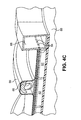
- FIGS. 4A-4C show details of the isolator section of ramjet of FIG. 2 including a portion of the heat exchanger of FIG. 3 .
- FIG. 5 is a schematic section view of a portion of an alternative heat exchanger.
- FIG. 1 is a schematic view of vehicle 10 including fuselage 12, wing 14, tail assembly 16, engine 18, and cowl 20.
- Vehicle 10 may be, for example, a manned aircraft. Alternative vehicles may be unmanned and may be reusable or may be one-way vehicles (e.g., missiles or disposable launch vehicles). Although this description is made with reference to a vehicle, embodiments of the present invention are applicable to any platform that includes demanding thermal management and power generation needs.
- wing 14 and tail assembly 16 are supported by fuselage 12.
- Engine 18 is located in cowl 20 on an underside of fuselage 12.
- Air flow path 24 carries a flow 26 through engine 18 between a forward inlet/intake 28 and an aft outlet 30 (e.g., an exhaust nozzle).
- FIG. 2 is a schematic view of engine 18 located in cowl 20.
- Engine 18 includes gas turbine 32 and ramjet 34.
- An exemplary ramjet is a dual mode (i.e., subsonic and supersonic combustion) ramjet engine (i.e., a dual mode scramjet).
- a ramjet generally comprises a constricted tube through which inlet air is compressed by the high speed of the vehicle, a combustion chamber where fuel and compressed air are combusted, and a nozzle through which the exhaust jet leaves at higher speed than the inlet air, thereby generating thrust to power a vehicle in flight.
- There are few or no moving parts in a ramjet In particular, there is no highspeed turbine, as in a turbofan or turbojet engine, that is expensive to produce and maintain.
- a ramjet requires airflow through the engine (in a scramjet the airflow must be supersonic), and therefore has a minimum functional speed.
- turbine 32 may be used to power vehicle 10 up to an appropriate speed beyond which ramjet 34 may augment or replace turbine 32 to power vehicle 10.
- a portion 26a of air flow 26 can be directed along flow path 36 into turbine 32, while another portion 26b of flow 26 can be directed along flow path 38 into ramjet 34.
- Flow path 38 carries flow 26b through ramjet 34 between forward inlet/intake 28 and aft outlet 30.
- ramjet 34 may include a forebody 34a, an isolator 34b (often integrated therewith), and a combustor 34c.
- air is scooped into ramjet 34 through forebody 34a and compressed along isolator 34b before entering combustor 34c. The compressed air is mixed with fuel in combustor 34c and ignited.
- engine 18 may also include control system 40 configured to control operation of combustor 34c in response to one or more of sensor input, operator input, and the like. Control system 40 may optionally be included as a portion of the avionics of vehicle 10.
- Gas turbine 32 is located along air flow path 36 carrying flow 26a between a forward inlet/intake 42 and an aft outlet 44 inboard of ramjet flow path 26b (e.g., partially recessed into fuselage 12 above cowl 20).
- Ramjet and turbine inlet flaps 46 and 48 can selectively block ramjet and turbine inlets 28, 42 and flow paths 38, 36 when ramjet 34 or turbine 32, respectively, is not in operation.
- turbine outlet flap 50 may selectively block turbine flow path 36 when turbine 32 is not in use so as to provide an efficient nozzle for ramjet 34.
- FIG. 3 is a schematic axial section view showing further details of the ramjet engine 34 and flow 26b. At least a portion of flow 26b is largely surrounded by heat exchanger (or conduit assembly) 60 for transferring heat from the air and combustion gases in ramjet 34 to pre-combustion ramjet fuel.
- a radially inward face of heat exchanger (or HEX) 60 forms a gas flow conduit through which flow 26b of ramjet 34 passes.
- Heat exchanger 60 can be formed as a generally rectangular conduit surrounding flow 26b, sometimes referred to as a 2-D configuration, or as an annular conduit circumscribing flow 26b, sometimes referred to as a 3-D configuration.
- heat exchanger 60 is a liquid-fuel-cooled heat exchanger.
- An alternative fuel used to cool heat exchanger 60 is a hydrogen gas.
- Heat exchanger 60 can have an upstream fuel inlet 62 and a downstream fuel outlet 64. In the illustrated embodiment, the inlet 62 is upstream of combustor 34c along flow path 26b. Heat exchanger 60 can thereby be used to pre-heat the fuel used in combustor 34c using the hot air and fuel mixture exiting combustor 34c.
- Fuel flow 66 of ramjet 34 can extend from storage tank 68 to fuel pump 70 and then to inlet 62. After exiting outlet 64, heated fuel may pass along flow path 72 to a fuel distribution valve network 74 and then to combustor 34c.
- the valves of network 74 distribute the fuel to various combustor locations for various purposes (e.g., piloting v. main combustion) and to achieve desired staging.
- heat exchanger 60 thermoelectrically generates electricity. Accordingly, exchanger 60 can be coupled to an electrical power conditioning, storage, and distribution system, such as system 76 shown schematically in FIG. 3 .
- System 76 can receive raw electrical input from heat exchanger 60 and output appropriate electricity (e.g., of a constant and proper voltage) to drive, for example, control system 40, fuel pump 70, distribution valves of the network 74, similar components associated with turbine 32, and additional loads schematically shown as 78.
- FIGS. 4A-4C show details of a portion of ramjet 34, including isolator 34b and a portion of heat exchanger 60.
- FIG. 4A is a perspective view of isolator 34b including heat exchanger 60.
- FIGS. 4B and 4C are cut-away perspective views showing details of heat exchanger 60.
- Heat exchanger 60 includes gas flow conduit 80, thermoelectric (TE) devices 82, fuel-cooled tubes 84, one or more springs 86, manifolds 88, and casing 90.
- gas flow conduit 80 surrounds a gas flow, such as flow 26b shown in FIGS 2 and 3 , and is formed as annular or 3-D type conduit.
- gas flow conduit 80 can be manufactured from, for example, high temperature alloys or ceramics, or a ceramic matrix composite (CMC).
- CMC is approximately one third the density of metal and therefore provides significant weight savings over a metal conduit.
- a metal may tend to overheat because TE devices 82 act as a thermal insulator between the material of conduit 80 and fuel-cooled tubes 84.
- CMC can operate at higher temperatures than metal, which makes it less likely to overheat in such applications.
- the CMC material, as well as other components of the heat exchanger 60, can optionally include suitable coatings as desired for particular applications.
- Conduit 80 is arranged between the gas flow and TE devices 82.
- TE devices 82 Adjacent to (e.g., radially outward from) TE devices 82 are fuel-cooled tubes 84. TE devices 82 are therefore arranged between the relatively hot gas flow conduit 80 and the relatively cool fuel-cooled tubes 84, to enable generation of electricity from the thermal differential therebetween. Individual fuel-cooled tubes allow an opening through which electrical leads for TE devices 82 can pass, which facilitates assembly of heat exchanger 60.
- TE devices produce a voltage in the presence of a temperature difference between two different electrically conductive materials.
- the voltage causes a continuous electrical current to flow in the conductors if they form a complete loop.
- the electrical current generated may be used to, for example, power accessory systems on an aircraft as discussed with reference to FIG. 3 above.
- TE devices function best with optimal thermal contact, and thereby thermal conduction, between the TE device and, for example, a gas flow conduit of a fuel-cooled heat exchanger.
- manufacturing and assembly tolerances, variations in position and size in components during operation, and other factors may degrade contact between the TE device and the conduit.
- Embodiments of the present invention employ one or more springs 86 to bias TE devices 82 into contact with the relatively hot gas flow conduit 80 and the relatively cool fuel-cooled tubes 84 between which the TE devices 82 are arranged.
- the load placed on TE devices 82 by the springs 86 helps ensure substantially continuous physical contact, while remaining below the structural limits of TE devices 82.
- a functional range for TE devices 82 used in embodiments of the present invention is approximately 140 to 350 kPa (20 to 50 psi).
- TE devices 82 exhibit dimensional variations caused by both manufacturing tolerances and operational effects, e.g. thermal expansion during flight.
- dimensional variations in TE devices 82 may adversely affect thermal conduction by varying the amount of contact between fuel-cooled tubes84 and TE devices 82 over which tubes 84 are arranged.
- Embodiments of the present invention therefore employ individual flexible fuel-cooled tubes 84, as opposed to, for example, sets of multiple interconnected rigid tubes, that can better accommodate dimensional variations in TE devices 82.
- the individual fuel-cooled tubes 84 can have a width dimension that is smaller that a corresponding dimension of each TE device 82, thereby allowing for compensation in dimensions across a single TE device 82.
- gas flow conduit 80 has an annular, generally cylindrical shape through which gas flow 26b can pass.
- conduit 80 provides primary structural support for heat exchanger 60.
- Conduit 80 is surrounded by TE devices 82, which are in turn surrounded by fuel-cooled tubes 84.
- heat exchanger 60 can include many individual TE devices 82 and fuel-cooled tubes 84 arranged in combination to substantially cover gas flow conduit 80.
- fuel-cooled tubes 84 extend generally axially from a first to a second end of the isolator 34b section of heat exchanger 60.
- the first and second ends of fuel-cooled tubes 84 are each fluidically connected to one of two annular manifolds 88, which are configured to carry pre-combustion fuel to and from tubes 84.
- Fuel-cooled tubes 84 can be arranged substantially perpendicular to each manifold 88, and can have a substantially rectangular cross-sectional profile to provide increased surface area exposure for thermal energy transfer.
- Manifolds can each have a substantially rectangular cross-sectional profile.
- Fuel-cooled tubes 84 are flexible, in part, because they are individual tubes with a high length to width ratio.
- Thermo-structural analysis predicts that a wall thickness of 0.38 mm (0.015 inches) will be sufficient for tubes 84 made of INCONEL alloy (available from Special Metals Corporation, Huntington, West Virginia) at 6.9 MPa (1 kpsi) internal pressure operating in a temperature range of approximately 20-650° C (68-1202° F) which are typical of the conditions in a hypersonic HEX application.
- At least partially circumscribing gas flow conduit 80, TE devices 82, and fuel-cooled tubes 84 are one or more springs 86 spaced from one another.
- the springs 86 extend circumferentially to at least partially circumscribe the flow path 26b, and are axially spaced from one another.
- Casing 90 encases and helps compress springs 86 in order to help keep TE devices 82 in contact with fuel-cooled tubes 84 and gas flow conduit 80. In that way, inwardly-directed compressive loading is provided. Controlled pressure can be applied to the back of each individual fuel-cooled tube 84 by springs 86, which are in compression between tubes 84 and casing 90.
- Canted coil springs can be selected for the springs 86, as shown in the illustrated embodiment, because they can provide a relatively constant load over a large displacement. A relatively constant load over a large displacement reduces a risk of overloading the TE devices as dimensional variations in the heat exchanger occur during operation.
- Custom designed Canted-CoilTM springs suitable for use as springs 86 are available from Bal Seal Engineering, Inc. of Foothill Collins, California.
- Casing 90 can be made of a metallic material.
- casing 90 has a generally corrugated configuration that defines circumferentially-extending channels to accommodate springs 86.
- Embodiments of the present invention can also be applied to a 2-D type heat exchanger application as shown in FIG. 5 , which is a schematic section view of a portion of alternative heat exchanger 100 including gas flow conduit 102, thermoelectric (TE) devices 104, fuel-cooled tubes 106, one ore more springs 108 (e.g., canted coil springs), supports 110, casing 112, fasteners 114, and insulation 116.
- gas flow conduit 102 surrounds a gas flow path and is formed as a 2-D conduit, i.e., a conduit with a generally rectangular cross-section.
- gas flow conduit 102 can be manufactured from, for example, high temperature alloys or ceramics, or a CMC material.
- Conduit 102 is arranged between gas flow path 26b and TE devices 104.
- Adjacent to (e.g., radially outward from) TE devices 104 are fuel-cooled tubes 106.
- TE devices 104 are therefore arranged between the relatively hot gas flow conduit 102 and the relatively cool fuel-cooled tubes 106 to enable generation of electricity from a thermal differential therebetween.
- Supports 110 extend between casing 112 and gas flow conduit 102.
- Springs 108 are arranged between fuel-cooled tubes 106 and casing 112.
- Casing 112 is attached to supports 110 by fasteners 114, which are configured to help compress springs 108 against fuel-cooled tubes 106 to bring TE devices 104 into contact with fuel-cooled tubes 106 and gas flow conduit 102. In that way an inwardly-directed compressive force is provided.
- insulation 116 can be provided to form a junction between banks of TE devices 104, fuel-cooled tubes 106, and springs 108 that are arranged generally perpendicular to each other. It should be noted that as used herein, springs 108 are described as circumscribing the flow path 26b in the embodiment of FIG. 6, even though springs 108 do not have a circular arrangement.
- heat exchangers according to the present invention help increase thermal conduction of the TE device by employing one or more generally circumferentially extending coil springs to bias the TE device into contact with the hot gas flow conduit and the cool fuel-cooled tubes between which the TE device is arranged.
- the load placed on the TE device by the springs is sufficient to ensure substantially continuous physical contact, while remaining below the structural limits of the TE device.
- Dimensional variations in the TE devices can be tolerated with the present invention because a width of the individually loaded fuel-cooled tubes can be significantly smaller than a corresponding width of the TE devices and therefore the pressure load will dynamically adjust to dimensional changes.
- the coil springs and flexible fuel-cooled tubes employed in embodiments of the present invention can also accommodate differential thermal growth between the various components in both steady state and transient conditions. Assembly time and manufacturing complexity is also relatively low.
- Embodiments of the present invention employing the annular or 3-D type configuration have additional benefits. Weight, complexity, and part count are reduced by employing a sealed casing that can help reduce or eliminate a need for fastener hardware, which can provide a weight savings of approximately 4 kg/m 2 according to inventor calculations. Furthermore, in prior art heat exchangers TE devices can suffer from oxidative degradation. With the present invention, the flow of oxidizing gases around the TE devices can be minimized by sealing them between the continuous gas flow conduit and the casing.
Abstract
Description
- Hypersonic vehicles hold potential for future military application by shortening the time-to-target and thereby extending global reach. These vehicles are anticipated to be powered by scramjet (supersonic combustion ramjet) engines during hypersonic flight conditions. The structure which forms the hypersonic flow path in a scramjet engine is referred to in the art as a heat exchanger (HEX), which is a reference to the dual use of the flow conduit structure as a heat exchanger. Hypersonic HEXs are commonly fuel-cooled because air-cooling is not practical in hypersonic flight conditions. Fuel cooling also serves to preheat the combustion fuel, thereby adding energy to the fuel for combustion. In conventional jet engines, fuel pumps, on-board electric systems, and other accessory systems parasitically draw power from the engine's main power plant to function. However, unlike conventional jet engines, scramjet engines have no rotating mechanical elements. Hypersonic vehicles are therefore currently envisioned to rely on auxiliary power units (APUs) and/or batteries to meet the vehicle power requirements. However, both APUs and battery systems add significant weight, volume and system complexity.
- An apparatus according to the present invention includes a thermoelectric (TE) device, a gas flow conduit proximate to one side of the thermoelectric device, a plurality of flexible tubes proximate to a second side of the thermoelectric device, and a spring to control contact force between the flexible tubes and the thermoelectric device. The spring comprises a coil spring at least partially circumscribing the gas flow conduit. The thermoelectric device converts a temperature differential between the flexible tubes and the gas flow conduit into electrical energy.
-
FIG. 1 is a schematic view of vehicle including hybrid gas turbine and ramjet engine. -
FIG. 2 is a schematic view of the hybrid gas turbine and ramjet engine ofFIG. 1 . -
FIG. 3 is a schematic axial section view of the ramjet ofFIG. 2 including a fuel-cooled heat exchanger. -
FIGS. 4A-4C show details of the isolator section of ramjet ofFIG. 2 including a portion of the heat exchanger ofFIG. 3 . -
FIG. 5 is a schematic section view of a portion of an alternative heat exchanger. -
FIG. 1 is a schematic view ofvehicle 10 includingfuselage 12,wing 14,tail assembly 16,engine 18, andcowl 20.Vehicle 10 may be, for example, a manned aircraft. Alternative vehicles may be unmanned and may be reusable or may be one-way vehicles (e.g., missiles or disposable launch vehicles). Although this description is made with reference to a vehicle, embodiments of the present invention are applicable to any platform that includes demanding thermal management and power generation needs. InFIG. 1 ,wing 14 andtail assembly 16 are supported byfuselage 12.Engine 18 is located incowl 20 on an underside offuselage 12.Air flow path 24 carries aflow 26 throughengine 18 between a forward inlet/intake 28 and an aft outlet 30 (e.g., an exhaust nozzle). -
FIG. 2 is a schematic view ofengine 18 located incowl 20.Engine 18 includesgas turbine 32 andramjet 34. An exemplary ramjet is a dual mode (i.e., subsonic and supersonic combustion) ramjet engine (i.e., a dual mode scramjet). A ramjet generally comprises a constricted tube through which inlet air is compressed by the high speed of the vehicle, a combustion chamber where fuel and compressed air are combusted, and a nozzle through which the exhaust jet leaves at higher speed than the inlet air, thereby generating thrust to power a vehicle in flight. There are few or no moving parts in a ramjet. In particular, there is no highspeed turbine, as in a turbofan or turbojet engine, that is expensive to produce and maintain. A ramjet requires airflow through the engine (in a scramjet the airflow must be supersonic), and therefore has a minimum functional speed. For example, in the hybrid vehicle shown inFIGS. 1-3 ,turbine 32 may be used to powervehicle 10 up to an appropriate speed beyond whichramjet 34 may augment or replaceturbine 32 topower vehicle 10. - In
FIG. 2 , aportion 26a ofair flow 26 can be directed alongflow path 36 intoturbine 32, while anotherportion 26b offlow 26 can be directed alongflow path 38 intoramjet 34.Flow path 38 carriesflow 26b throughramjet 34 between forward inlet/intake 28 andaft outlet 30. Alongflow path 38,ramjet 34 may include aforebody 34a, anisolator 34b (often integrated therewith), and acombustor 34c. During operation, air is scooped intoramjet 34 throughforebody 34a and compressed alongisolator 34b before enteringcombustor 34c. The compressed air is mixed with fuel incombustor 34c and ignited. The products of combustion are exhausted throughoutlet 30 to produce useful thrust used to powervehicle 10 in flight. As shown inFIG. 2 ,engine 18 may also includecontrol system 40 configured to control operation ofcombustor 34c in response to one or more of sensor input, operator input, and the like.Control system 40 may optionally be included as a portion of the avionics ofvehicle 10. -
Gas turbine 32 is located alongair flow path 36 carryingflow 26a between a forward inlet/intake 42 and anaft outlet 44 inboard oframjet flow path 26b (e.g., partially recessed intofuselage 12 above cowl 20). Ramjet andturbine inlet flaps turbine inlets flow paths ramjet 34 orturbine 32, respectively, is not in operation. Similarly,turbine outlet flap 50 may selectively blockturbine flow path 36 whenturbine 32 is not in use so as to provide an efficient nozzle forramjet 34. -
FIG. 3 is a schematic axial section view showing further details of theramjet engine 34 and flow 26b. At least a portion offlow 26b is largely surrounded by heat exchanger (or conduit assembly) 60 for transferring heat from the air and combustion gases inramjet 34 to pre-combustion ramjet fuel. A radially inward face of heat exchanger (or HEX) 60 forms a gas flow conduit through which flow 26b oframjet 34 passes.Heat exchanger 60 can be formed as a generally rectangularconduit surrounding flow 26b, sometimes referred to as a 2-D configuration, or as an annular conduitcircumscribing flow 26b, sometimes referred to as a 3-D configuration. For an exemplary hydrocarbon-based fuel,heat exchanger 60 is a liquid-fuel-cooled heat exchanger. An alternative fuel used to coolheat exchanger 60 is a hydrogen gas.Heat exchanger 60 can have anupstream fuel inlet 62 and adownstream fuel outlet 64. In the illustrated embodiment, theinlet 62 is upstream ofcombustor 34c alongflow path 26b.Heat exchanger 60 can thereby be used to pre-heat the fuel used incombustor 34c using the hot air and fuelmixture exiting combustor 34c.Fuel flow 66 oframjet 34 can extend fromstorage tank 68 tofuel pump 70 and then to inlet 62. After exitingoutlet 64, heated fuel may pass along flow path 72 to a fueldistribution valve network 74 and then tocombustor 34c. The valves ofnetwork 74 distribute the fuel to various combustor locations for various purposes (e.g., piloting v. main combustion) and to achieve desired staging. - In addition to pre-heating combustion fuel,
heat exchanger 60 thermoelectrically generates electricity. Accordingly,exchanger 60 can be coupled to an electrical power conditioning, storage, and distribution system, such assystem 76 shown schematically inFIG. 3 .System 76 can receive raw electrical input fromheat exchanger 60 and output appropriate electricity (e.g., of a constant and proper voltage) to drive, for example,control system 40,fuel pump 70, distribution valves of thenetwork 74, similar components associated withturbine 32, and additional loads schematically shown as 78. -
FIGS. 4A-4C show details of a portion oframjet 34, includingisolator 34b and a portion ofheat exchanger 60.FIG. 4A is a perspective view ofisolator 34b includingheat exchanger 60.FIGS. 4B and4C are cut-away perspective views showing details ofheat exchanger 60.Heat exchanger 60 includesgas flow conduit 80, thermoelectric (TE)devices 82, fuel-cooledtubes 84, one ormore springs 86,manifolds 88, andcasing 90. InFIGS. 4A-4C ,gas flow conduit 80 surrounds a gas flow, such asflow 26b shown inFIGS 2 and 3 , and is formed as annular or 3-D type conduit. In order to withstand the extreme operating temperatures of hypersonic flight,gas flow conduit 80 can be manufactured from, for example, high temperature alloys or ceramics, or a ceramic matrix composite (CMC). CMC is approximately one third the density of metal and therefore provides significant weight savings over a metal conduit. In some applications, a metal may tend to overheat becauseTE devices 82 act as a thermal insulator between the material ofconduit 80 and fuel-cooledtubes 84. CMC can operate at higher temperatures than metal, which makes it less likely to overheat in such applications. The CMC material, as well as other components of theheat exchanger 60, can optionally include suitable coatings as desired for particular applications.Conduit 80 is arranged between the gas flow andTE devices 82. Adjacent to (e.g., radially outward from)TE devices 82 are fuel-cooledtubes 84.TE devices 82 are therefore arranged between the relatively hotgas flow conduit 80 and the relatively cool fuel-cooledtubes 84, to enable generation of electricity from the thermal differential therebetween. Individual fuel-cooled tubes allow an opening through which electrical leads forTE devices 82 can pass, which facilitates assembly ofheat exchanger 60. - Generally speaking, TE devices produce a voltage in the presence of a temperature difference between two different electrically conductive materials. The voltage causes a continuous electrical current to flow in the conductors if they form a complete loop. The electrical current generated may be used to, for example, power accessory systems on an aircraft as discussed with reference to
FIG. 3 above. TE devices function best with optimal thermal contact, and thereby thermal conduction, between the TE device and, for example, a gas flow conduit of a fuel-cooled heat exchanger. However, manufacturing and assembly tolerances, variations in position and size in components during operation, and other factors may degrade contact between the TE device and the conduit. Embodiments of the present invention employ one ormore springs 86 tobias TE devices 82 into contact with the relatively hotgas flow conduit 80 and the relatively cool fuel-cooledtubes 84 between which theTE devices 82 are arranged. The load placed onTE devices 82 by thesprings 86, directly or indirectly, helps ensure substantially continuous physical contact, while remaining below the structural limits ofTE devices 82. For example, a functional range forTE devices 82 used in embodiments of the present invention is approximately 140 to 350 kPa (20 to 50 psi). - In practice,
TE devices 82 exhibit dimensional variations caused by both manufacturing tolerances and operational effects, e.g. thermal expansion during flight. For instance, dimensional variations inTE devices 82 may adversely affect thermal conduction by varying the amount of contact between fuel-cooled tubes84 andTE devices 82 over whichtubes 84 are arranged. Embodiments of the present invention therefore employ individual flexible fuel-cooledtubes 84, as opposed to, for example, sets of multiple interconnected rigid tubes, that can better accommodate dimensional variations inTE devices 82. Furthermore, the individual fuel-cooledtubes 84 can have a width dimension that is smaller that a corresponding dimension of eachTE device 82, thereby allowing for compensation in dimensions across asingle TE device 82. - In
FIGS. 4A-4C ,gas flow conduit 80 has an annular, generally cylindrical shape through whichgas flow 26b can pass. In the illustrated embodiment,conduit 80 provides primary structural support forheat exchanger 60.Conduit 80 is surrounded byTE devices 82, which are in turn surrounded by fuel-cooledtubes 84. As shown inFIGS. 4B and4C ,heat exchanger 60 can include manyindividual TE devices 82 and fuel-cooledtubes 84 arranged in combination to substantially covergas flow conduit 80. In the illustrated embodiment, fuel-cooledtubes 84 extend generally axially from a first to a second end of theisolator 34b section ofheat exchanger 60. The first and second ends of fuel-cooledtubes 84 are each fluidically connected to one of twoannular manifolds 88, which are configured to carry pre-combustion fuel to and fromtubes 84. Fuel-cooledtubes 84 can be arranged substantially perpendicular to each manifold 88, and can have a substantially rectangular cross-sectional profile to provide increased surface area exposure for thermal energy transfer. Manifolds can each have a substantially rectangular cross-sectional profile. Fuel-cooledtubes 84 are flexible, in part, because they are individual tubes with a high length to width ratio. Thermo-structural analysis predicts that a wall thickness of 0.38 mm (0.015 inches) will be sufficient fortubes 84 made of INCONEL alloy (available from Special Metals Corporation, Huntington, West Virginia) at 6.9 MPa (1 kpsi) internal pressure operating in a temperature range of approximately 20-650° C (68-1202° F) which are typical of the conditions in a hypersonic HEX application. - At least partially circumscribing
gas flow conduit 80,TE devices 82, and fuel-cooledtubes 84 are one ormore springs 86 spaced from one another. In the illustrated embodiment, thesprings 86 extend circumferentially to at least partially circumscribe theflow path 26b, and are axially spaced from one another.Casing 90 encases and helps compresssprings 86 in order to help keepTE devices 82 in contact with fuel-cooledtubes 84 andgas flow conduit 80. In that way, inwardly-directed compressive loading is provided. Controlled pressure can be applied to the back of each individual fuel-cooledtube 84 bysprings 86, which are in compression betweentubes 84 andcasing 90. Canted coil springs can be selected for thesprings 86, as shown in the illustrated embodiment, because they can provide a relatively constant load over a large displacement. A relatively constant load over a large displacement reduces a risk of overloading the TE devices as dimensional variations in the heat exchanger occur during operation. Custom designed Canted-Coil™ springs suitable for use assprings 86 are available from Bal Seal Engineering, Inc. of Foothill Ranch, California. -
Casing 90 can be made of a metallic material. In the illustrated embodiment, casing 90 has a generally corrugated configuration that defines circumferentially-extending channels to accommodatesprings 86. - Embodiments of the present invention can also be applied to a 2-D type heat exchanger application as shown in
FIG. 5 , which is a schematic section view of a portion of alternative heat exchanger 100 includinggas flow conduit 102, thermoelectric (TE)devices 104, fuel-cooledtubes 106, one ore more springs 108 (e.g., canted coil springs), supports 110, casing 112,fasteners 114, andinsulation 116. As shown inFIG. 5 ,gas flow conduit 102 surrounds a gas flow path and is formed as a 2-D conduit, i.e., a conduit with a generally rectangular cross-section. In order to withstand the extreme operating temperatures of hypersonic flight,gas flow conduit 102 can be manufactured from, for example, high temperature alloys or ceramics, or a CMC material.Conduit 102 is arranged betweengas flow path 26b andTE devices 104. Adjacent to (e.g., radially outward from)TE devices 104 are fuel-cooledtubes 106.TE devices 104 are therefore arranged between the relatively hotgas flow conduit 102 and the relatively cool fuel-cooledtubes 106 to enable generation of electricity from a thermal differential therebetween.Supports 110 extend betweencasing 112 andgas flow conduit 102.Springs 108 are arranged between fuel-cooledtubes 106 andcasing 112. Casing 112 is attached tosupports 110 byfasteners 114, which are configured to help compresssprings 108 against fuel-cooledtubes 106 to bringTE devices 104 into contact with fuel-cooledtubes 106 andgas flow conduit 102. In that way an inwardly-directed compressive force is provided. At corners of heat exchanger 100,insulation 116 can be provided to form a junction between banks ofTE devices 104, fuel-cooledtubes 106, and springs 108 that are arranged generally perpendicular to each other. It should be noted that as used herein, springs 108 are described as circumscribing theflow path 26b in the embodiment of FIG. 6, even thoughsprings 108 do not have a circular arrangement. - Those of ordinary skill in the art will recognize that embodiments of the present invention provide numerous advantages over prior heat exchangers employing TE devices. For example, heat exchangers according to the present invention help increase thermal conduction of the TE device by employing one or more generally circumferentially extending coil springs to bias the TE device into contact with the hot gas flow conduit and the cool fuel-cooled tubes between which the TE device is arranged. The load placed on the TE device by the springs is sufficient to ensure substantially continuous physical contact, while remaining below the structural limits of the TE device. Dimensional variations in the TE devices can be tolerated with the present invention because a width of the individually loaded fuel-cooled tubes can be significantly smaller than a corresponding width of the TE devices and therefore the pressure load will dynamically adjust to dimensional changes. The coil springs and flexible fuel-cooled tubes employed in embodiments of the present invention can also accommodate differential thermal growth between the various components in both steady state and transient conditions. Assembly time and manufacturing complexity is also relatively low.
- Embodiments of the present invention employing the annular or 3-D type configuration have additional benefits. Weight, complexity, and part count are reduced by employing a sealed casing that can help reduce or eliminate a need for fastener hardware, which can provide a weight savings of approximately 4 kg/m2 according to inventor calculations. Furthermore, in prior art heat exchangers TE devices can suffer from oxidative degradation. With the present invention, the flow of oxidizing gases around the TE devices can be minimized by sealing them between the continuous gas flow conduit and the casing.
- While the invention has been described with reference to an exemplary embodiment(s), it will be understood by those skilled in the art that various changes may be made and equivalents may be substituted for elements thereof without departing from the scope of the invention, which is defined by the appended claims. For example, the present invention can be utilized with a variety of types of engines for electrical power generation. Moreover, the springs of the heat exchanger can be arranged in a helical pattern.
Claims (14)
- An apparatus comprising:a thermoelectric (TE) device;a gas flow conduit proximate to one side of the thermoelectric device;a plurality of flexible tubes proximate to a second side of the thermoelectric device; anda spring to control contact force between the flexible tubes and the thermoelectric device, wherein the spring comprises a coil spring at least partially circumscribing the gas flow conduit;wherein the thermoelectric device may convert a temperature differential between the flexible tubes and the gas flow conduit into electrical energy.
- The apparatus of claim 1 configured for a fuel to flow through the flexible tubes and thereby cool the flexible tubes.
- The apparatus of claim 1 or 2 wherein the gas flow conduit further comprises a ceramic matrix composite.
- The apparatus of claim 1, 2 or 3
wherein each of the flexible tubes extends between a first and a second end of the gas flow conduit; and
wherein at least one of the first and the second ends of each of the flexible tubes is connected to a manifold configured to carry a fluid. - The apparatus of claim 1, 2, 3 or 4
wherein the gas flow conduit is formed in a generally annular shape; and
wherein the coil spring is arranged substantially circumferentially with respect to the gas flow conduit. - The heat exchanger of claim 1, 2, 3 or 4
wherein the gas flow conduit is formed in a generally rectangular cross-sectional shape, and
wherein the spring substantially surrounds the flexible fuel-cooled tubes. - The apparatus of any preceding claim, wherein the spring is configured to apply a load on the TE device of approximately 140 to 350 kPa (20 to 50 psi).
- The apparatus of any preceding claim, wherein the spring is a canted coil spring.
- The apparatus of claim 10 and further comprising one or more additional coil springs spaced apart from one another.
- A ramjet comprising apparatus as claimed in any preceding claim in the form of a conduit assembly surrounding a gas flow path of the ramjet, the conduit assembly comprising:said gas flow conduit arranged adjacent the gas flow path;said plurality of flexible tubes configured to be cooled by a fuel flowable therethrough;said thermoelectric (TE) device, for converting a thermal energy differential into electrical energy, arranged between the gas flow conduit and the flexible tubes; andsaid coil spring configured to bias the TE device into contact with the gas flow conduit and the flexible tubes, wherein the coil spring at least partially circumscribes the gas flow path;
a combustor arranged aftward of the conduit assembly; and
an outlet conduit arranged aftward of the combustor. - The ramjet of claim 10,
wherein the gas flow conduit, the TE device, and the flexible tubes are formed in a generally annular shape in a direction substantially perpendicular to the gas flow path; and
wherein the coil spring is arranged substantially circumferentially with respect to the gas flow path. - The ramjet of claim 10,
wherein the gas flow conduit, the TE device, and the flexible tubes are formed in a generally rectangular cross-sectional shape in a direction substantially perpendicular to the gas flow path;
wherein the coil spring substantially surrounds the flexible tubes;
wherein each of the flexible tubes extends between a first and a second end of the conduit; and
wherein one or both of the first and the second ends of each of the flexible tubes is connected to a manifold configured to carry the fuel. - A vehicle comprising:a fuselage; and
a ramjet as claimed in claim 10, 11 or 12 connected to the fuselage. - The vehicle of claim 13, wherein the gas flow conduit, the TE device, and the flexible fuel-cooled tubes are formed in a generally rectangular cross-sectional shape in a direction substantially perpendicular to the gas flow path.
Applications Claiming Priority (2)
| Application Number | Priority Date | Filing Date | Title |
|---|---|---|---|
| US21101309P | 2009-03-25 | 2009-03-25 | |
| US12/550,106 US8453456B2 (en) | 2009-03-25 | 2009-08-28 | Fuel-cooled flexible heat exchanger with thermoelectric device compression |
Publications (3)
| Publication Number | Publication Date |
|---|---|
| EP2233727A2 true EP2233727A2 (en) | 2010-09-29 |
| EP2233727A3 EP2233727A3 (en) | 2014-03-12 |
| EP2233727B1 EP2233727B1 (en) | 2017-12-13 |
Family
ID=42200051
Family Applications (1)
| Application Number | Title | Priority Date | Filing Date |
|---|---|---|---|
| EP10250566.6A Active EP2233727B1 (en) | 2009-03-25 | 2010-03-25 | Fuel-cooled flexible heat exchanger with thermoelectric device compression |
Country Status (2)
| Country | Link |
|---|---|
| US (1) | US8453456B2 (en) |
| EP (1) | EP2233727B1 (en) |
Cited By (3)
| Publication number | Priority date | Publication date | Assignee | Title |
|---|---|---|---|---|
| EP2762705A3 (en) * | 2013-01-30 | 2018-01-24 | Mitsubishi Heavy Industries, Ltd. | Fuel supply system, scramjet engine and method for operating the same |
| EP3591210A4 (en) * | 2017-04-10 | 2020-03-04 | Mitsubishi Heavy Industries, Ltd. | Regenerative cooler for ramjet engine, and method for manufacturing same |
| CN112431688A (en) * | 2020-11-20 | 2021-03-02 | 西安航天动力研究所 | High-temperature pure air test system of scramjet engine |
Families Citing this family (9)
| Publication number | Priority date | Publication date | Assignee | Title |
|---|---|---|---|---|
| US8522560B2 (en) * | 2009-03-25 | 2013-09-03 | United Technologies Corporation | Fuel-cooled heat exchanger with thermoelectric device compression |
| GB2496839A (en) * | 2011-10-24 | 2013-05-29 | Ge Aviat Systems Ltd | Thermal electrical power generation for aircraft |
| JP6099402B2 (en) * | 2013-01-10 | 2017-03-22 | 三菱重工業株式会社 | Combustor |
| WO2014113018A1 (en) * | 2013-01-18 | 2014-07-24 | United Technologies Corporation | Combined ceramic matrix composite and thermoelectric structure for electric power generation |
| US20150315966A1 (en) * | 2014-05-01 | 2015-11-05 | The Boeing Company | Hypersonic Vehicle Base Drag Reduction and Improved Inlet Performance Through Venting Forebody Bleed Air to Base Area Using Open Core Ceramic Composites |
| US10436115B2 (en) | 2016-08-22 | 2019-10-08 | United Technologies Corporation | Heat exchanger for gas turbine engine with support damper mounting |
| CN110318878B (en) * | 2019-06-13 | 2022-08-09 | 内蒙动力机械研究所 | Aerospace plane active cooling system based on magnetofluid energy bypass |
| US11840929B2 (en) * | 2020-05-13 | 2023-12-12 | Rtx Corporation | Radial seal arrangement |
| US20220252012A1 (en) * | 2021-02-11 | 2022-08-11 | General Electric Company | Flowpath assembly with composite tube array |
Family Cites Families (40)
| Publication number | Priority date | Publication date | Assignee | Title |
|---|---|---|---|---|
| US2990775A (en) | 1958-02-24 | 1961-07-04 | Henson West | Cooling system based on thermoelectric principles |
| NL246977A (en) * | 1958-12-31 | |||
| US3169030A (en) * | 1961-05-26 | 1965-02-09 | United Aircraft Corp | Releasable attachment device |
| US3733826A (en) | 1964-02-10 | 1973-05-22 | Texaco Experiment Inc | Fuel cooled ram air reaction propulsion engine |
| US4065936A (en) | 1976-06-16 | 1978-01-03 | Borg-Warner Corporation | Counter-flow thermoelectric heat pump with discrete sections |
| US4372211A (en) | 1980-04-14 | 1983-02-08 | The United States Of America As Represented By The Secretary Of The Army | Thermoelectric power supply for warheads |
| US4580524A (en) | 1984-09-07 | 1986-04-08 | The United States Of America As Represented By The United States Department Of Energy | Process for the preparation of fiber-reinforced ceramic composites by chemical vapor deposition |
| US5135184A (en) | 1990-08-22 | 1992-08-04 | The Johns Hopkins University | Propellant utilization system |
| US5337975A (en) | 1992-02-28 | 1994-08-16 | Rockwell International Corporation | Breathing system for hypersonic aircraft |
| US5584183A (en) * | 1994-02-18 | 1996-12-17 | Solid State Cooling Systems | Thermoelectric heat exchanger |
| US5874775A (en) | 1994-08-03 | 1999-02-23 | Sumitomo Electric Industries, Ltd. | Diamond heat sink including microchannel therein and methods for manufacturing diamond heat sinks |
| DE19602731C1 (en) * | 1996-01-26 | 1997-07-10 | Daimler Benz Aerospace Ag | Reduced thermal stress wall structure for a rocket drive mechanism |
| KR20000010903A (en) * | 1996-05-10 | 2000-02-25 | 존 엠 쉬뢰더 | Improved thermoelectric unit with electric input/output provision |
| DE19746229B4 (en) | 1996-10-18 | 2019-08-01 | Nikon Corp. | Progressive multifocal lens |
| AU6783598A (en) | 1997-03-31 | 1998-10-22 | Research Triangle Institute | Thin-film thermoelectric device and fabrication method of same |
| JPH1187786A (en) * | 1997-09-08 | 1999-03-30 | Seru Appl Kk | Electron cooling/heating apparatus |
| US6045310A (en) | 1997-10-06 | 2000-04-04 | United Technologies Corporation | Composite fastener for use in high temperature environments |
| US6042315A (en) | 1997-10-06 | 2000-03-28 | United Technologies Corporation | Fastener |
| FR2782378B1 (en) * | 1998-08-14 | 2000-11-10 | Snecma | STRUCTURAL PART COMPRISING A PART OF THERMOSTRUCTURAL COMPOSITE MATERIAL COOLED BY FLUID CIRCULATION |
| US6345507B1 (en) | 2000-09-29 | 2002-02-12 | Electrografics International Corporation | Compact thermoelectric cooling system |
| US6627019B2 (en) | 2000-12-18 | 2003-09-30 | David C. Jarmon | Process for making ceramic matrix composite parts with cooling channels |
| AU2002346863A1 (en) * | 2001-06-07 | 2002-12-16 | Mark Salerno | Method and apparatus for modular embedded control system |
| KR100452909B1 (en) | 2001-12-29 | 2004-10-14 | 한국동서발전(주) | Apparatus for generating thermoelectric semiconductor using of exhaust gas heat |
| KR20030064292A (en) | 2002-01-25 | 2003-07-31 | 가부시키가이샤 고마쓰 세이사쿠쇼 | Thermoelectric module |
| US6907920B2 (en) | 2002-01-29 | 2005-06-21 | United Technologies Corporation | Heat exchanger panel |
| FR2836698B1 (en) | 2002-03-04 | 2005-02-11 | Eads Launch Vehicles | COMBUSTION CHAMBER FOR STATOREACTOR AND STATOREACTOR PROVIDED WITH SUCH A COMBUSTION CHAMBER |
| FR2838183B1 (en) * | 2002-04-09 | 2004-07-09 | Snecma Propulsion Solide | HIGH TEMPERATURE HEAT EXCHANGER STRUCTURE |
| US20030234008A1 (en) | 2002-06-20 | 2003-12-25 | John Van Winkle | Dual cooling intake system for an internal combustion engine |
| US20040045594A1 (en) | 2002-09-10 | 2004-03-11 | Enhanced Energy Systems, Inc. | Turbine engine with thermoelectric waste heat recovery system |
| US7210653B2 (en) | 2002-10-22 | 2007-05-01 | The Boeing Company | Electric-based secondary power system architectures for aircraft |
| JP3722439B2 (en) | 2002-11-06 | 2005-11-30 | 川重冷熱工業株式会社 | Hybrid thermoelectric supply system |
| EP1420206B1 (en) | 2002-11-13 | 2007-07-18 | Coprecitec, S.L. | Combustion detection apparatus with a thermoelectric generator |
| WO2004059138A1 (en) | 2002-12-26 | 2004-07-15 | Toyota Jidosha Kabushiki Kaisha | Exhaust heat power generation apparatus |
| US6834831B2 (en) | 2002-12-31 | 2004-12-28 | The Boeing Company | Hybrid solid oxide fuel cell aircraft auxiliary power unit |
| US20050022855A1 (en) | 2003-07-30 | 2005-02-03 | Raver Bernard J. | Thermoelectric power generator for a gas turbine engine |
| US20060063522A1 (en) | 2004-09-21 | 2006-03-23 | Mcfarland Norman R | Self-powering automated building control components |
| US7254953B2 (en) | 2005-01-06 | 2007-08-14 | Caterpillar Inc | Thermoelectric heat exchange element |
| US8313056B2 (en) | 2005-07-19 | 2012-11-20 | United Technologies Corporation | Engine heat exchanger with thermoelectric generation |
| US7385503B1 (en) | 2006-08-03 | 2008-06-10 | Rosemount, Inc. | Self powered son device network |
| US8378205B2 (en) | 2006-09-29 | 2013-02-19 | United Technologies Corporation | Thermoelectric heat exchanger |
-
2009
- 2009-08-28 US US12/550,106 patent/US8453456B2/en active Active
-
2010
- 2010-03-25 EP EP10250566.6A patent/EP2233727B1/en active Active
Non-Patent Citations (1)
| Title |
|---|
| None |
Cited By (6)
| Publication number | Priority date | Publication date | Assignee | Title |
|---|---|---|---|---|
| EP2762705A3 (en) * | 2013-01-30 | 2018-01-24 | Mitsubishi Heavy Industries, Ltd. | Fuel supply system, scramjet engine and method for operating the same |
| US10190540B2 (en) | 2013-01-30 | 2019-01-29 | Mitsubishi Heavy Industries, Ltd. | Fuel supply system, scramjet engine and method for operating the same |
| EP3591210A4 (en) * | 2017-04-10 | 2020-03-04 | Mitsubishi Heavy Industries, Ltd. | Regenerative cooler for ramjet engine, and method for manufacturing same |
| US11512852B2 (en) | 2017-04-10 | 2022-11-29 | Mitsubishi Heavy Industries, Ltd. | Regeneration cooler of ramjet engine, and manufacturing method of the same |
| CN112431688A (en) * | 2020-11-20 | 2021-03-02 | 西安航天动力研究所 | High-temperature pure air test system of scramjet engine |
| CN112431688B (en) * | 2020-11-20 | 2021-11-02 | 西安航天动力研究所 | High-temperature pure air test system of scramjet engine |
Also Published As
| Publication number | Publication date |
|---|---|
| US8453456B2 (en) | 2013-06-04 |
| EP2233727A3 (en) | 2014-03-12 |
| EP2233727B1 (en) | 2017-12-13 |
| US20100242437A1 (en) | 2010-09-30 |
Similar Documents
| Publication | Publication Date | Title |
|---|---|---|
| EP2233727B1 (en) | Fuel-cooled flexible heat exchanger with thermoelectric device compression | |
| EP2233728B1 (en) | Fuel-cooled heat exchanger with thermoelectric device compression | |
| US8127555B2 (en) | Flowpath heat exchanger for thermal management and power generation within a hypersonic vehicle | |
| EP1746257B1 (en) | Vehicle and corresponding operating method | |
| US10533481B2 (en) | Thermal electric assembly attached on an outer surface of a hot section of a gas turbine engine to generate electrical power | |
| US11846248B1 (en) | Integrated vehicle fluids | |
| US9810153B2 (en) | Engine | |
| EP4215730A1 (en) | Hydrogen powered geared turbo fan engine with an off-set reduced core | |
| US10717550B1 (en) | Integrated vehicle fluids | |
| EP4089271A1 (en) | Turbine engines having hydrogen fuel systems | |
| CN113014144B (en) | Forced cooling thermoelectric power generation system of miniature turbojet engine | |
| US20120168121A1 (en) | Internal pocket fastener system for ceramic matrix composite heat exchanger | |
| US11661908B2 (en) | Airbreathing engine module with reverse flow arrangement | |
| EP4303418A1 (en) | Hybrid electric power for turbine engines having hydrogen fuel systems | |
| US11665963B1 (en) | Waste heat capture using tail cone of a gas turbine engine | |
| US20230304439A1 (en) | Turbine engines having hydrogen fuel systems | |
| EP4303416A1 (en) | Turbo expanders for turbine engines having hydrogen fuel systems | |
| KR20190118854A (en) | Engine heat exchanger with thermoelectric generation |
Legal Events
| Date | Code | Title | Description |
|---|---|---|---|
| PUAI | Public reference made under article 153(3) epc to a published international application that has entered the european phase |
Free format text: ORIGINAL CODE: 0009012 |
|
| AK | Designated contracting states |
Kind code of ref document: A2 Designated state(s): AT BE BG CH CY CZ DE DK EE ES FI FR GB GR HR HU IE IS IT LI LT LU LV MC MK MT NL NO PL PT RO SE SI SK SM TR |
|
| AX | Request for extension of the european patent |
Extension state: AL BA ME RS |
|
| PUAL | Search report despatched |
Free format text: ORIGINAL CODE: 0009013 |
|
| AK | Designated contracting states |
Kind code of ref document: A3 Designated state(s): AT BE BG CH CY CZ DE DK EE ES FI FR GB GR HR HU IE IS IT LI LT LU LV MC MK MT NL NO PL PT RO SE SI SK SM TR |
|
| AX | Request for extension of the european patent |
Extension state: AL BA ME RS |
|
| RIC1 | Information provided on ipc code assigned before grant |
Ipc: F01D 13/00 20060101ALI20140205BHEP Ipc: F02K 7/16 20060101ALI20140205BHEP Ipc: F02K 1/82 20060101ALI20140205BHEP Ipc: B64D 37/34 20060101ALI20140205BHEP Ipc: F02C 7/224 20060101ALI20140205BHEP Ipc: F02K 9/97 20060101ALI20140205BHEP Ipc: B64D 33/08 20060101ALI20140205BHEP Ipc: F02K 9/64 20060101ALI20140205BHEP Ipc: B64D 33/02 20060101ALI20140205BHEP Ipc: F01D 25/08 20060101ALI20140205BHEP Ipc: F02K 7/14 20060101ALI20140205BHEP Ipc: B64C 30/00 20060101ALI20140205BHEP Ipc: F02K 7/10 20060101AFI20140205BHEP Ipc: F02C 6/18 20060101ALI20140205BHEP |
|
| 17P | Request for examination filed |
Effective date: 20140911 |
|
| RBV | Designated contracting states (corrected) |
Designated state(s): AT BE BG CH CY CZ DE DK EE ES FI FR GB GR HR HU IE IS IT LI LT LU LV MC MK MT NL NO PL PT RO SE SI SK SM TR |
|
| RAP1 | Party data changed (applicant data changed or rights of an application transferred) |
Owner name: UNITED TECHNOLOGIES CORPORATION |
|
| GRAP | Despatch of communication of intention to grant a patent |
Free format text: ORIGINAL CODE: EPIDOSNIGR1 |
|
| INTG | Intention to grant announced |
Effective date: 20170616 |
|
| GRAS | Grant fee paid |
Free format text: ORIGINAL CODE: EPIDOSNIGR3 |
|
| GRAA | (expected) grant |
Free format text: ORIGINAL CODE: 0009210 |
|
| AK | Designated contracting states |
Kind code of ref document: B1 Designated state(s): AT BE BG CH CY CZ DE DK EE ES FI FR GB GR HR HU IE IS IT LI LT LU LV MC MK MT NL NO PL PT RO SE SI SK SM TR |
|
| REG | Reference to a national code |
Ref country code: GB Ref legal event code: FG4D |
|
| REG | Reference to a national code |
Ref country code: AT Ref legal event code: REF Ref document number: 954629 Country of ref document: AT Kind code of ref document: T Effective date: 20171215 Ref country code: CH Ref legal event code: EP |
|
| REG | Reference to a national code |
Ref country code: IE Ref legal event code: FG4D |
|
| REG | Reference to a national code |
Ref country code: DE Ref legal event code: R096 Ref document number: 602010047310 Country of ref document: DE |
|
| REG | Reference to a national code |
Ref country code: FR Ref legal event code: PLFP Year of fee payment: 9 |
|
| REG | Reference to a national code |
Ref country code: NL Ref legal event code: MP Effective date: 20171213 |
|
| REG | Reference to a national code |
Ref country code: LT Ref legal event code: MG4D |
|
| PG25 | Lapsed in a contracting state [announced via postgrant information from national office to epo] |
Ref country code: NO Free format text: LAPSE BECAUSE OF FAILURE TO SUBMIT A TRANSLATION OF THE DESCRIPTION OR TO PAY THE FEE WITHIN THE PRESCRIBED TIME-LIMIT Effective date: 20180313 Ref country code: LT Free format text: LAPSE BECAUSE OF FAILURE TO SUBMIT A TRANSLATION OF THE DESCRIPTION OR TO PAY THE FEE WITHIN THE PRESCRIBED TIME-LIMIT Effective date: 20171213 Ref country code: FI Free format text: LAPSE BECAUSE OF FAILURE TO SUBMIT A TRANSLATION OF THE DESCRIPTION OR TO PAY THE FEE WITHIN THE PRESCRIBED TIME-LIMIT Effective date: 20171213 Ref country code: SE Free format text: LAPSE BECAUSE OF FAILURE TO SUBMIT A TRANSLATION OF THE DESCRIPTION OR TO PAY THE FEE WITHIN THE PRESCRIBED TIME-LIMIT Effective date: 20171213 |
|
| REG | Reference to a national code |
Ref country code: AT Ref legal event code: MK05 Ref document number: 954629 Country of ref document: AT Kind code of ref document: T Effective date: 20171213 |
|
| PG25 | Lapsed in a contracting state [announced via postgrant information from national office to epo] |
Ref country code: LV Free format text: LAPSE BECAUSE OF FAILURE TO SUBMIT A TRANSLATION OF THE DESCRIPTION OR TO PAY THE FEE WITHIN THE PRESCRIBED TIME-LIMIT Effective date: 20171213 Ref country code: BG Free format text: LAPSE BECAUSE OF FAILURE TO SUBMIT A TRANSLATION OF THE DESCRIPTION OR TO PAY THE FEE WITHIN THE PRESCRIBED TIME-LIMIT Effective date: 20180313 Ref country code: GR Free format text: LAPSE BECAUSE OF FAILURE TO SUBMIT A TRANSLATION OF THE DESCRIPTION OR TO PAY THE FEE WITHIN THE PRESCRIBED TIME-LIMIT Effective date: 20180314 Ref country code: HR Free format text: LAPSE BECAUSE OF FAILURE TO SUBMIT A TRANSLATION OF THE DESCRIPTION OR TO PAY THE FEE WITHIN THE PRESCRIBED TIME-LIMIT Effective date: 20171213 |
|
| PG25 | Lapsed in a contracting state [announced via postgrant information from national office to epo] |
Ref country code: NL Free format text: LAPSE BECAUSE OF FAILURE TO SUBMIT A TRANSLATION OF THE DESCRIPTION OR TO PAY THE FEE WITHIN THE PRESCRIBED TIME-LIMIT Effective date: 20171213 |
|
| PG25 | Lapsed in a contracting state [announced via postgrant information from national office to epo] |
Ref country code: ES Free format text: LAPSE BECAUSE OF FAILURE TO SUBMIT A TRANSLATION OF THE DESCRIPTION OR TO PAY THE FEE WITHIN THE PRESCRIBED TIME-LIMIT Effective date: 20171213 Ref country code: SK Free format text: LAPSE BECAUSE OF FAILURE TO SUBMIT A TRANSLATION OF THE DESCRIPTION OR TO PAY THE FEE WITHIN THE PRESCRIBED TIME-LIMIT Effective date: 20171213 Ref country code: CY Free format text: LAPSE BECAUSE OF FAILURE TO SUBMIT A TRANSLATION OF THE DESCRIPTION OR TO PAY THE FEE WITHIN THE PRESCRIBED TIME-LIMIT Effective date: 20171213 Ref country code: CZ Free format text: LAPSE BECAUSE OF FAILURE TO SUBMIT A TRANSLATION OF THE DESCRIPTION OR TO PAY THE FEE WITHIN THE PRESCRIBED TIME-LIMIT Effective date: 20171213 Ref country code: EE Free format text: LAPSE BECAUSE OF FAILURE TO SUBMIT A TRANSLATION OF THE DESCRIPTION OR TO PAY THE FEE WITHIN THE PRESCRIBED TIME-LIMIT Effective date: 20171213 |
|
| PG25 | Lapsed in a contracting state [announced via postgrant information from national office to epo] |
Ref country code: SM Free format text: LAPSE BECAUSE OF FAILURE TO SUBMIT A TRANSLATION OF THE DESCRIPTION OR TO PAY THE FEE WITHIN THE PRESCRIBED TIME-LIMIT Effective date: 20171213 Ref country code: PL Free format text: LAPSE BECAUSE OF FAILURE TO SUBMIT A TRANSLATION OF THE DESCRIPTION OR TO PAY THE FEE WITHIN THE PRESCRIBED TIME-LIMIT Effective date: 20171213 Ref country code: IT Free format text: LAPSE BECAUSE OF FAILURE TO SUBMIT A TRANSLATION OF THE DESCRIPTION OR TO PAY THE FEE WITHIN THE PRESCRIBED TIME-LIMIT Effective date: 20171213 Ref country code: AT Free format text: LAPSE BECAUSE OF FAILURE TO SUBMIT A TRANSLATION OF THE DESCRIPTION OR TO PAY THE FEE WITHIN THE PRESCRIBED TIME-LIMIT Effective date: 20171213 Ref country code: RO Free format text: LAPSE BECAUSE OF FAILURE TO SUBMIT A TRANSLATION OF THE DESCRIPTION OR TO PAY THE FEE WITHIN THE PRESCRIBED TIME-LIMIT Effective date: 20171213 Ref country code: IS Free format text: LAPSE BECAUSE OF FAILURE TO SUBMIT A TRANSLATION OF THE DESCRIPTION OR TO PAY THE FEE WITHIN THE PRESCRIBED TIME-LIMIT Effective date: 20180413 |
|
| REG | Reference to a national code |
Ref country code: DE Ref legal event code: R097 Ref document number: 602010047310 Country of ref document: DE |
|
| PLBE | No opposition filed within time limit |
Free format text: ORIGINAL CODE: 0009261 |
|
| STAA | Information on the status of an ep patent application or granted ep patent |
Free format text: STATUS: NO OPPOSITION FILED WITHIN TIME LIMIT |
|
| REG | Reference to a national code |
Ref country code: CH Ref legal event code: PL |
|
| 26N | No opposition filed |
Effective date: 20180914 |
|
| PG25 | Lapsed in a contracting state [announced via postgrant information from national office to epo] |
Ref country code: MC Free format text: LAPSE BECAUSE OF FAILURE TO SUBMIT A TRANSLATION OF THE DESCRIPTION OR TO PAY THE FEE WITHIN THE PRESCRIBED TIME-LIMIT Effective date: 20171213 Ref country code: DK Free format text: LAPSE BECAUSE OF FAILURE TO SUBMIT A TRANSLATION OF THE DESCRIPTION OR TO PAY THE FEE WITHIN THE PRESCRIBED TIME-LIMIT Effective date: 20171213 |
|
| REG | Reference to a national code |
Ref country code: BE Ref legal event code: MM Effective date: 20180331 |
|
| REG | Reference to a national code |
Ref country code: IE Ref legal event code: MM4A |
|
| PG25 | Lapsed in a contracting state [announced via postgrant information from national office to epo] |
Ref country code: LU Free format text: LAPSE BECAUSE OF NON-PAYMENT OF DUE FEES Effective date: 20180325 |
|
| PG25 | Lapsed in a contracting state [announced via postgrant information from national office to epo] |
Ref country code: IE Free format text: LAPSE BECAUSE OF NON-PAYMENT OF DUE FEES Effective date: 20180325 |
|
| PG25 | Lapsed in a contracting state [announced via postgrant information from national office to epo] |
Ref country code: CH Free format text: LAPSE BECAUSE OF NON-PAYMENT OF DUE FEES Effective date: 20180331 Ref country code: SI Free format text: LAPSE BECAUSE OF FAILURE TO SUBMIT A TRANSLATION OF THE DESCRIPTION OR TO PAY THE FEE WITHIN THE PRESCRIBED TIME-LIMIT Effective date: 20171213 Ref country code: LI Free format text: LAPSE BECAUSE OF NON-PAYMENT OF DUE FEES Effective date: 20180331 Ref country code: BE Free format text: LAPSE BECAUSE OF NON-PAYMENT OF DUE FEES Effective date: 20180331 |
|
| PG25 | Lapsed in a contracting state [announced via postgrant information from national office to epo] |
Ref country code: MT Free format text: LAPSE BECAUSE OF NON-PAYMENT OF DUE FEES Effective date: 20180325 |
|
| PG25 | Lapsed in a contracting state [announced via postgrant information from national office to epo] |
Ref country code: TR Free format text: LAPSE BECAUSE OF FAILURE TO SUBMIT A TRANSLATION OF THE DESCRIPTION OR TO PAY THE FEE WITHIN THE PRESCRIBED TIME-LIMIT Effective date: 20171213 |
|
| PG25 | Lapsed in a contracting state [announced via postgrant information from national office to epo] |
Ref country code: PT Free format text: LAPSE BECAUSE OF FAILURE TO SUBMIT A TRANSLATION OF THE DESCRIPTION OR TO PAY THE FEE WITHIN THE PRESCRIBED TIME-LIMIT Effective date: 20171213 Ref country code: HU Free format text: LAPSE BECAUSE OF FAILURE TO SUBMIT A TRANSLATION OF THE DESCRIPTION OR TO PAY THE FEE WITHIN THE PRESCRIBED TIME-LIMIT; INVALID AB INITIO Effective date: 20100325 |
|
| PG25 | Lapsed in a contracting state [announced via postgrant information from national office to epo] |
Ref country code: MK Free format text: LAPSE BECAUSE OF NON-PAYMENT OF DUE FEES Effective date: 20171213 |
|
| REG | Reference to a national code |
Ref country code: DE Ref legal event code: R081 Ref document number: 602010047310 Country of ref document: DE Owner name: RAYTHEON TECHNOLOGIES CORPORATION (N.D.GES.D.S, US Free format text: FORMER OWNER: UNITED TECHNOLOGIES CORPORATION, FARMINGTON, CONN., US |
|
| PGFP | Annual fee paid to national office [announced via postgrant information from national office to epo] |
Ref country code: FR Payment date: 20230222 Year of fee payment: 14 |
|
| PGFP | Annual fee paid to national office [announced via postgrant information from national office to epo] |
Ref country code: GB Payment date: 20230222 Year of fee payment: 14 Ref country code: DE Payment date: 20230221 Year of fee payment: 14 |
|
| P01 | Opt-out of the competence of the unified patent court (upc) registered |
Effective date: 20230519 |