EP2233716A1 - Fuel injection method for diesel engine and diesel engine - Google Patents
Fuel injection method for diesel engine and diesel engine Download PDFInfo
- Publication number
- EP2233716A1 EP2233716A1 EP08860579A EP08860579A EP2233716A1 EP 2233716 A1 EP2233716 A1 EP 2233716A1 EP 08860579 A EP08860579 A EP 08860579A EP 08860579 A EP08860579 A EP 08860579A EP 2233716 A1 EP2233716 A1 EP 2233716A1
- Authority
- EP
- European Patent Office
- Prior art keywords
- fuel injection
- fuel
- combustion chamber
- piston
- diesel engine
- Prior art date
- Legal status (The legal status is an assumption and is not a legal conclusion. Google has not performed a legal analysis and makes no representation as to the accuracy of the status listed.)
- Granted
Links
- 239000000446 fuel Substances 0.000 title claims abstract description 99
- 238000002347 injection Methods 0.000 title claims abstract description 63
- 239000007924 injection Substances 0.000 title claims abstract description 63
- 238000000034 method Methods 0.000 title claims description 9
- 238000002485 combustion reaction Methods 0.000 claims abstract description 35
- 230000000630 rising effect Effects 0.000 claims abstract description 7
- 230000006835 compression Effects 0.000 claims description 6
- 238000007906 compression Methods 0.000 claims description 6
- 239000007789 gas Substances 0.000 description 11
- 239000013618 particulate matter Substances 0.000 description 7
- QVGXLLKOCUKJST-UHFFFAOYSA-N atomic oxygen Chemical compound [O] QVGXLLKOCUKJST-UHFFFAOYSA-N 0.000 description 2
- 238000000889 atomisation Methods 0.000 description 2
- 230000000694 effects Effects 0.000 description 2
- 238000004519 manufacturing process Methods 0.000 description 2
- 239000000203 mixture Substances 0.000 description 2
- 239000001301 oxygen Substances 0.000 description 2
- 229910052760 oxygen Inorganic materials 0.000 description 2
- 238000012986 modification Methods 0.000 description 1
- 230000004048 modification Effects 0.000 description 1
- 230000010363 phase shift Effects 0.000 description 1
- 239000000243 solution Substances 0.000 description 1
- 230000007704 transition Effects 0.000 description 1
Images

Classifications
-
- F—MECHANICAL ENGINEERING; LIGHTING; HEATING; WEAPONS; BLASTING
- F02—COMBUSTION ENGINES; HOT-GAS OR COMBUSTION-PRODUCT ENGINE PLANTS
- F02M—SUPPLYING COMBUSTION ENGINES IN GENERAL WITH COMBUSTIBLE MIXTURES OR CONSTITUENTS THEREOF
- F02M61/00—Fuel-injectors not provided for in groups F02M39/00 - F02M57/00 or F02M67/00
- F02M61/14—Arrangements of injectors with respect to engines; Mounting of injectors
-
- F—MECHANICAL ENGINEERING; LIGHTING; HEATING; WEAPONS; BLASTING
- F02—COMBUSTION ENGINES; HOT-GAS OR COMBUSTION-PRODUCT ENGINE PLANTS
- F02B—INTERNAL-COMBUSTION PISTON ENGINES; COMBUSTION ENGINES IN GENERAL
- F02B23/00—Other engines characterised by special shape or construction of combustion chambers to improve operation
- F02B23/02—Other engines characterised by special shape or construction of combustion chambers to improve operation with compression ignition
- F02B23/06—Other engines characterised by special shape or construction of combustion chambers to improve operation with compression ignition the combustion space being arranged in working piston
- F02B23/0645—Details related to the fuel injector or the fuel spray
- F02B23/0648—Means or methods to improve the spray dispersion, evaporation or ignition
- F02B23/0651—Means or methods to improve the spray dispersion, evaporation or ignition the fuel spray impinging on reflecting surfaces or being specially guided throughout the combustion space
-
- F—MECHANICAL ENGINEERING; LIGHTING; HEATING; WEAPONS; BLASTING
- F02—COMBUSTION ENGINES; HOT-GAS OR COMBUSTION-PRODUCT ENGINE PLANTS
- F02B—INTERNAL-COMBUSTION PISTON ENGINES; COMBUSTION ENGINES IN GENERAL
- F02B23/00—Other engines characterised by special shape or construction of combustion chambers to improve operation
- F02B23/02—Other engines characterised by special shape or construction of combustion chambers to improve operation with compression ignition
- F02B23/06—Other engines characterised by special shape or construction of combustion chambers to improve operation with compression ignition the combustion space being arranged in working piston
- F02B23/0645—Details related to the fuel injector or the fuel spray
- F02B23/0663—Details related to the fuel injector or the fuel spray having multiple injectors per combustion chamber
-
- F—MECHANICAL ENGINEERING; LIGHTING; HEATING; WEAPONS; BLASTING
- F02—COMBUSTION ENGINES; HOT-GAS OR COMBUSTION-PRODUCT ENGINE PLANTS
- F02B—INTERNAL-COMBUSTION PISTON ENGINES; COMBUSTION ENGINES IN GENERAL
- F02B23/00—Other engines characterised by special shape or construction of combustion chambers to improve operation
- F02B23/02—Other engines characterised by special shape or construction of combustion chambers to improve operation with compression ignition
- F02B23/06—Other engines characterised by special shape or construction of combustion chambers to improve operation with compression ignition the combustion space being arranged in working piston
- F02B23/0678—Unconventional, complex or non-rotationally symmetrical shapes of the combustion space, e.g. flower like, having special shapes related to the orientation of the fuel spray jets
- F02B23/069—Unconventional, complex or non-rotationally symmetrical shapes of the combustion space, e.g. flower like, having special shapes related to the orientation of the fuel spray jets characterised by its eccentricity from the cylinder axis
-
- F—MECHANICAL ENGINEERING; LIGHTING; HEATING; WEAPONS; BLASTING
- F02—COMBUSTION ENGINES; HOT-GAS OR COMBUSTION-PRODUCT ENGINE PLANTS
- F02B—INTERNAL-COMBUSTION PISTON ENGINES; COMBUSTION ENGINES IN GENERAL
- F02B2275/00—Other engines, components or details, not provided for in other groups of this subclass
- F02B2275/14—Direct injection into combustion chamber
-
- F—MECHANICAL ENGINEERING; LIGHTING; HEATING; WEAPONS; BLASTING
- F02—COMBUSTION ENGINES; HOT-GAS OR COMBUSTION-PRODUCT ENGINE PLANTS
- F02M—SUPPLYING COMBUSTION ENGINES IN GENERAL WITH COMBUSTIBLE MIXTURES OR CONSTITUENTS THEREOF
- F02M61/00—Fuel-injectors not provided for in groups F02M39/00 - F02M57/00 or F02M67/00
- F02M61/16—Details not provided for in, or of interest apart from, the apparatus of groups F02M61/02 - F02M61/14
- F02M61/18—Injection nozzles, e.g. having valve seats; Details of valve member seated ends, not otherwise provided for
- F02M61/1806—Injection nozzles, e.g. having valve seats; Details of valve member seated ends, not otherwise provided for characterised by the arrangement of discharge orifices, e.g. orientation or size
- F02M61/1813—Discharge orifices having different orientations with respect to valve member direction of movement, e.g. orientations being such that fuel jets emerging from discharge orifices collide with each other
-
- Y—GENERAL TAGGING OF NEW TECHNOLOGICAL DEVELOPMENTS; GENERAL TAGGING OF CROSS-SECTIONAL TECHNOLOGIES SPANNING OVER SEVERAL SECTIONS OF THE IPC; TECHNICAL SUBJECTS COVERED BY FORMER USPC CROSS-REFERENCE ART COLLECTIONS [XRACs] AND DIGESTS
- Y02—TECHNOLOGIES OR APPLICATIONS FOR MITIGATION OR ADAPTATION AGAINST CLIMATE CHANGE
- Y02T—CLIMATE CHANGE MITIGATION TECHNOLOGIES RELATED TO TRANSPORTATION
- Y02T10/00—Road transport of goods or passengers
- Y02T10/10—Internal combustion engine [ICE] based vehicles
- Y02T10/12—Improving ICE efficiencies
Definitions
- the present invention relates to a fuel injection method for a diesel engine and a diesel engine.
- injection pressure of the fuel in, for example, an initial stage of fuel injection is reduced to reduce an amount of air (oxygen) to be mixed with the fuel.
- air oxygen
- vigorous combustion of the fuel in the initial stage of fuel injection is suppressed to prevent flame temperature from being increased, thereby suppressing production of NO x in exhaust gas.
- Patent Literature 1 A conventional diesel engine is disclosed, for example, in Patent Literature 1. Also in the Patent Literature 1, injection pressure of fuel is reduced to prevent excessive oxygen from being introduced into the fuel to thereby suppress production of NO x in exhaust gas.
- Patent Literature 1 JP 2003-65169A
- the invention was made in view of the above and has its object to provide a fuel injection method for a diesel engine and a diesel engine capable of reducing NO x and particulate matter in exhaust gas.
- the invention is directed to a fuel injection method for a diesel engine with fuel injection valves for injection of fuel into a combustion chamber, which comprises injecting the fuel crosswise of the combustion chamber from the plural fuel injection valves arranged horizontally and diametrically oppositely of the combustion chamber in a plan view and arranged out of alignment axially of the combustion chamber, the fuel injected from the fuel injection valve close to a cylinder head colliding with the fuel injected from the fuel injection valve away from the cylinder head to rise along a slant on a piston with a rising gradient from a side adjacent to the fuel injection valve away from the cylinder head toward a side adjacent to the fuel injection valve close to the cylinder head up to diametrically halfway of the piston when the piston is in a vicinity of an upper dead center during a compression stroke, the fuel injected from the respective fuel injection valves advancing toward opposing wall portions in the combustion chamber when the piston is lowered by a predetermined amount during an expansion stroke.
- the invention is also directed to a diesel engine with fuel injection valves for injection of fuel into a combustion chamber, comprising the fuel injection valves arranged horizontally and diametrically oppositely of the combustion chamber in a plan view and arranged out of alignment axially of the combustion chamber, and a piston with an upper surface having a rising gradient extending from a side adjacent to the fuel injection valve away from a cylinder head toward a side adjacent to the fuel injection valve close to the cylinder head up to diametrically halfway of the piston.
- a fuel injection method for a diesel engine and a diesel engine according to the invention exhibit excellent effects that, in the initial stage of fuel injection, the involvement of air into the fuel is restricted so that flame temperature is prevented from being enhanced and NO x in the exhaust gas can be reduced and that, in the late stage of fuel injection, air can be sufficiently involved into the injected fuel so that the combustion becomes satisfactory to reduce the particulate matter.
- Figs. 1-6 shows the embodiment of the invention.
- reference numeral 1 denotes a diesel engine.
- the diesel engine 1 comprises a cylinder 2, a piston 3 slidably arranged in the cylinder 2 for reciprocal movements in the cylinder 2, two fuel injection valves 6a and 6b for injection of fuel 5a, 5b into a combustion chamber 4 at an upper portion of the cylinder 2 from diametrically outwardly, and openable and closable suction and exhaust valves (not shown) attached to a cylinder head 7.
- the fuel injection valves 6a and 6b are arranged circumferentially of the cylinder 2 and with a 180° phase shift to each other about an axis L of the cylinder 2 (combustion chamber 4) and with a height difference by distance S to each other in a direction parallel to the axis L; the fuel injection valves 6a and 6b are formed at their tips with a plurality of nozzle holes 8a and 8b, respectively, for example at a central and lateral positions as shown in Figs. 5 and 6 .
- An upper surface of the piston 3 has a rising gradient from its side adjacent to the fuel injection valve 6b, positioned away from the cylinder head 7, toward its side adjacent to the fuel injection valve 6a, positioned close to the cylinder head 7, said rising gradient extending up to a vicinity of a center O of the piston 3 to thereby provide a slant 3a with a slant angle ⁇ of about 15°-25°.
- the fuel 5a, 5b collides with each other diametrically centrally of the cylinder 2 and its advance velocities cancel out each other and an involved air amount is restricted, so that the combustion becomes moderate.
- the injected fuel 5a, 5b may be stably ignited, so that the combustion temperature of the fuel 5a, 5b does not become enhanced and NO x in the exhaust gas is reduced.
- the injected fuel 5a, 5b from the fuel injection valves 6a and 6b proceeds across the combustion chamber 4 toward the opposing wall portions as shown in Fig. 3 ; there is no confliction between the fuel 5a, 5b.
- air is satisfactorily mixed with the fuel 5a, 5b, so that the fuel 5a, 5b is burned well to reduce the particulate matter in the exhaust gas.
- the involvement of air into the fuel 5a, 5b is restricted so that flame temperature is prevented from being enhanced and NO x in the exhaust gas can be reduced.
- air can be sufficiently involved into the injected fuel 5a, 5b, so that the combustion becomes satisfactory to reduce the particulate matter.
- a fuel injection method for a diesel engine and a diesel engine according to the invention have been described with respect to a case where the fuel is directly injected from the fuel injection valves into the combustion chamber. It is to be understood that various changes and modifications may be made without departing from the scope of the invention. For example, the invention may be carried out in such a manner that arranged diametrically oppositely of the cylinder are auxiliary chambers through which the injected fuel is introduced from the fuel injection valves into the combustion chamber.
Landscapes
- Engineering & Computer Science (AREA)
- Chemical & Material Sciences (AREA)
- Combustion & Propulsion (AREA)
- Mechanical Engineering (AREA)
- General Engineering & Computer Science (AREA)
- Dispersion Chemistry (AREA)
- Combustion Methods Of Internal-Combustion Engines (AREA)
- Fuel-Injection Apparatus (AREA)
Abstract
Description
- The present invention relates to a fuel injection method for a diesel engine and a diesel engine.
- In a diesel engine, reduction of NOx and particulate matter (PM) in exhaust gas has been demanded. In a conventional diesel engine, when a piston reaches a vicinity of an upper dead center in a compression stroke, fuel is injected by fuel injection valves into atomization in a combustion chamber where the atomized fuel is mixed with air taken in through a suction valve to produce a fuel-air mixture which attains its ignition temperature through compression of the combustion chamber to burn.
- Conventionally, in order to reduce NOx in exhaust gas in such diesel engine, injection pressure of the fuel in, for example, an initial stage of fuel injection is reduced to reduce an amount of air (oxygen) to be mixed with the fuel. As a result, vigorous combustion of the fuel in the initial stage of fuel injection is suppressed to prevent flame temperature from being increased, thereby suppressing production of NOx in exhaust gas.
- A conventional diesel engine is disclosed, for example, in
Patent Literature 1. Also in thePatent Literature 1, injection pressure of fuel is reduced to prevent excessive oxygen from being introduced into the fuel to thereby suppress production of NOx in exhaust gas.
[Patent Literature 1]JP 2003-65169A - However, even if injection pressure of the fuel is reduced as mentioned in the above, the fuel is atomized to some extent so that air is admixed in the injected fuel to produce a fuel-air mixture, failing to sufficiently suppress increase of flame temperature. Thus, reduction of NOx in exhaust gas may be insufficient. Moreover, insufficient atomization of the fuel due to the reduced injection pressure may disadvantageously deteriorate the combustion to increase particulate matter in exhaust gas. It is considered that such problems are also brought about in the diesel engine of the
Patent Literature 1. - The invention was made in view of the above and has its object to provide a fuel injection method for a diesel engine and a diesel engine capable of reducing NOx and particulate matter in exhaust gas.
- The invention is directed to a fuel injection method for a diesel engine with fuel injection valves for injection of fuel into a combustion chamber, which comprises injecting the fuel crosswise of the combustion chamber from the plural fuel injection valves arranged horizontally and diametrically oppositely of the combustion chamber in a plan view and arranged out of alignment axially of the combustion chamber, the fuel injected from the fuel injection valve close to a cylinder head colliding with the fuel injected from the fuel injection valve away from the cylinder head to rise along a slant on a piston with a rising gradient from a side adjacent to the fuel injection valve away from the cylinder head toward a side adjacent to the fuel injection valve close to the cylinder head up to diametrically halfway of the piston when the piston is in a vicinity of an upper dead center during a compression stroke, the fuel injected from the respective fuel injection valves advancing toward opposing wall portions in the combustion chamber when the piston is lowered by a predetermined amount during an expansion stroke.
- The invention is also directed to a diesel engine with fuel injection valves for injection of fuel into a combustion chamber, comprising the fuel injection valves arranged horizontally and diametrically oppositely of the combustion chamber in a plan view and arranged out of alignment axially of the combustion chamber, and a piston with an upper surface having a rising gradient extending from a side adjacent to the fuel injection valve away from a cylinder head toward a side adjacent to the fuel injection valve close to the cylinder head up to diametrically halfway of the piston.
- A fuel injection method for a diesel engine and a diesel engine according to the invention exhibit excellent effects that, in the initial stage of fuel injection, the involvement of air into the fuel is restricted so that flame temperature is prevented from being enhanced and NOx in the exhaust gas can be reduced and that, in the late stage of fuel injection, air can be sufficiently involved into the injected fuel so that the combustion becomes satisfactory to reduce the particulate matter.
-
-
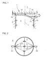
Fig. 1 shows a front view in section of an embodiment of a fuel injection method for a diesel engine and a diesel engine according to the invention in an initial stage of fuel injection where a piston is in a vicinity of an upper dead center; -
Fig. 2 is a plan view ofFig. 1 ; -
Fig. 3 shows a front view in section of the embodiment of a fuel injection method for a diesel engine and a diesel engine according to the invention in a late stage of fuel injection where the piston is lowered from the vicinity of the upper dead center by a predetermined distance; -
Fig. 4 is a plan view ofFig. 3 ; -
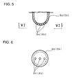
Fig. 5 is a horizontal section schematically showing a tip of a fuel injection valve; and -
Fig. 6 is a view looking in the direction of arrows VI inFig. 5 . -
- 1
- diesel engine
- 2
- cylinder
- 3
- piston
- 3a
- bevel
- 4
- combustion chamber
- 5a
- fuel
- 5b
- fuel
- 6a
- fuel injection valve
- 6b
- fuel injection valve
- 7
- cylinder head
- An embodiment of the invention will be described in conjunction with the attached drawings.
Figs. 1-6 shows the embodiment of the invention.
In the figures,reference numeral 1 denotes a diesel engine. Thediesel engine 1 comprises acylinder 2, apiston 3 slidably arranged in thecylinder 2 for reciprocal movements in thecylinder 2, twofuel injection valves fuel combustion chamber 4 at an upper portion of thecylinder 2 from diametrically outwardly, and openable and closable suction and exhaust valves (not shown) attached to acylinder head 7. - The
fuel injection valves cylinder 2 and with a 180° phase shift to each other about an axis L of the cylinder 2 (combustion chamber 4) and with a height difference by distance S to each other in a direction parallel to the axis L; thefuel injection valves nozzle holes Figs. 5 and 6 . An upper surface of thepiston 3 has a rising gradient from its side adjacent to thefuel injection valve 6b, positioned away from thecylinder head 7, toward its side adjacent to thefuel injection valve 6a, positioned close to thecylinder head 7, said rising gradient extending up to a vicinity of a center O of thepiston 3 to thereby provide a slant 3a with a slant angle α of about 15°-25°. - Next, a mode of operation of the above-mentioned embodiment will be described.
In thediesel engine 1, when thepiston 3 reaches the vicinity of the upper dead center during the compression stroke,fuel nozzle holes fuel injection valves combustion chamber 4 crosswise of thecombustion chamber 4 and the suction valve (not shown) is opened to introduce air into thecombustion chamber 4. Thus, in the initial stage of fuel injection where thepiston 3 is in the vicinity of the upper dead center, thefuel Fig. 2 . As shown inFig. 1 , thefuel 5a proceeds substantially horizontally whereas thefuel 5b proceeds substantially horizontally and then changes its direction along the slant 3a of thepiston 3 to proceed slantwise upwardly along the slant 3a. - As a result, the
fuel cylinder 2 and its advance velocities cancel out each other and an involved air amount is restricted, so that the combustion becomes moderate. Thus, the injectedfuel fuel - In the late stage of fuel injection where the
piston 3 is lowered by a predetermined distance in transition of thediesel engine 1 from the compression stroke into the expansion stroke, the injectedfuel fuel injection valves combustion chamber 4 toward the opposing wall portions as shown inFig. 3 ; there is no confliction between thefuel fuel fuel - According to the embodiment of the invention, in the initial stage of fuel injection, the involvement of air into the
fuel fuel - A fuel injection method for a diesel engine and a diesel engine according to the invention have been described with respect to a case where the fuel is directly injected from the fuel injection valves into the combustion chamber. It is to be understood that various changes and modifications may be made without departing from the scope of the invention. For example, the invention may be carried out in such a manner that arranged diametrically oppositely of the cylinder are auxiliary chambers through which the injected fuel is introduced from the fuel injection valves into the combustion chamber.
Claims (2)
- A fuel injection method for a diesel engine with fuel injection valves for injection of fuel into a combustion chamber,
characterized in that it comprises injecting the fuel crosswise of the combustion chamber from the plural fuel injection valves arranged horizontally and diametrically oppositely of the combustion chamber in a plan view and arranged out of alignment axially of the combustion chamber, the fuel injected from the fuel injection valve close to a cylinder head colliding with the fuel injected from the fuel injection valve away from the cylinder head to rise along a slant on a piston with a rising gradient from a side adjacent to the fuel injection valve away from the cylinder head toward a side adjacent to the fuel injection valve close to the cylinder head up to diametrically halfway of the piston when the piston is in a vicinity of an upper dead center during a compression stroke, the fuel injected from the respective fuel injection valves advancing toward opposing wall portions in the combustion chamber when the piston is lowered by a predetermined amount during an expansion stroke. - A diesel engine with fuel injection valves for injecting fuel into a combustion chamber, characterized by comprising the fuel injection valves arranged horizontally and diametrically oppositely of the combustion chamber in a plan view and arranged out of alignment axially of the combustion chamber, and a piston with an upper surface having a rising gradient extending from a side adjacent to the fuel injection valve away from a cylinder head toward a side adjacent to the fuel injection valve close to the cylinder head up to diametrically halfway of the piston.
Applications Claiming Priority (2)
| Application Number | Priority Date | Filing Date | Title |
|---|---|---|---|
| JP2007322311A JP5071088B2 (en) | 2007-12-13 | 2007-12-13 | Diesel engine fuel injection method and diesel engine |
| PCT/JP2008/003181 WO2009075055A1 (en) | 2007-12-13 | 2008-11-05 | Fuel injection method for diesel engine and diesel engine |
Publications (3)
| Publication Number | Publication Date |
|---|---|
| EP2233716A1 true EP2233716A1 (en) | 2010-09-29 |
| EP2233716A4 EP2233716A4 (en) | 2011-08-03 |
| EP2233716B1 EP2233716B1 (en) | 2016-01-27 |
Family
ID=40755305
Family Applications (1)
| Application Number | Title | Priority Date | Filing Date |
|---|---|---|---|
| EP08860579.5A Not-in-force EP2233716B1 (en) | 2007-12-13 | 2008-11-05 | Fuel injection method for diesel engine and diesel engine |
Country Status (4)
| Country | Link |
|---|---|
| US (1) | US8534262B2 (en) |
| EP (1) | EP2233716B1 (en) |
| JP (1) | JP5071088B2 (en) |
| WO (1) | WO2009075055A1 (en) |
Families Citing this family (1)
| Publication number | Priority date | Publication date | Assignee | Title |
|---|---|---|---|---|
| US10329997B2 (en) * | 2017-07-19 | 2019-06-25 | Ford Global Technologies, Llc | Diesel engine with dual fuel injection |
Family Cites Families (22)
| Publication number | Priority date | Publication date | Assignee | Title |
|---|---|---|---|---|
| JPS60187714A (en) | 1984-03-08 | 1985-09-25 | Mitsubishi Heavy Ind Ltd | Combustion chamber of diesel engine |
| JPS61207816A (en) * | 1985-03-11 | 1986-09-16 | Hiroichi Ikeda | Combustion chamber of diesel engine |
| JPS6415540A (en) | 1987-07-09 | 1989-01-19 | Bridgestone Corp | Cylindrical rubber vibration isolator |
| JP2933685B2 (en) | 1990-07-17 | 1999-08-16 | 松下電器産業株式会社 | Multiprocessor system |
| JPH0475158U (en) * | 1990-11-13 | 1992-06-30 | ||
| DE59406924D1 (en) * | 1993-10-29 | 1998-10-22 | Waertsilae Nsd Schweiz Ag | Reciprocating piston internal combustion engine of the diesel type |
| AT1974U1 (en) | 1997-02-10 | 1998-02-25 | Avl List Gmbh | FOUR-STOCK COMBUSTION ENGINE |
| JPH10227218A (en) | 1997-02-12 | 1998-08-25 | Isuzu Motors Ltd | diesel engine |
| JPH10232608A (en) * | 1997-02-19 | 1998-09-02 | Hiroshi Arai | Magic calendar |
| JPH10252608A (en) * | 1997-03-11 | 1998-09-22 | Toyota Motor Corp | Compression ignition type internal combustion engine |
| DE19807489A1 (en) | 1998-02-21 | 1999-08-26 | Daimler Chrysler Ag | Reciprocating piston of an internal combustion engine |
| SE519775C2 (en) * | 1998-05-14 | 2003-04-08 | Volvo Car Corp | Internal combustion engine |
| JP3812338B2 (en) * | 2001-01-05 | 2006-08-23 | 日産自動車株式会社 | In-cylinder direct fuel injection spark ignition engine |
| DE10293557D2 (en) | 2001-08-02 | 2004-07-01 | Cornel Stan | Mixture formation and combustion process for heat engines with direct fuel injection |
| JP2003065169A (en) | 2001-08-24 | 2003-03-05 | Toyota Motor Corp | Diesel engine combustion control |
| JP2003172144A (en) | 2001-12-05 | 2003-06-20 | Komatsu Ltd | Diesel engine and combustion method of diesel engine |
| JP2003328762A (en) * | 2002-05-14 | 2003-11-19 | Daihatsu Motor Co Ltd | Uniflow type two-cycle internal combustion engine |
| US6725828B1 (en) * | 2003-06-17 | 2004-04-27 | Ford Global Technologies, Llc | Vortex-induced stratification combustion for direct injection spark ignition engines |
| JP2007231913A (en) * | 2006-03-03 | 2007-09-13 | Toyota Motor Corp | Fuel injection device for internal combustion engine |
| JP2007255291A (en) * | 2006-03-23 | 2007-10-04 | Toyota Motor Corp | Fuel injection device for internal combustion engine |
| US7418940B1 (en) * | 2007-08-30 | 2008-09-02 | Ford Global Technologies, Llc | Fuel injector spray pattern for direct injection spark ignition engines |
| JP2009167878A (en) * | 2008-01-15 | 2009-07-30 | Hitachi Ltd | gasoline engine |
-
2007
- 2007-12-13 JP JP2007322311A patent/JP5071088B2/en not_active Expired - Fee Related
-
2008
- 2008-11-05 US US12/747,646 patent/US8534262B2/en not_active Expired - Fee Related
- 2008-11-05 WO PCT/JP2008/003181 patent/WO2009075055A1/en not_active Ceased
- 2008-11-05 EP EP08860579.5A patent/EP2233716B1/en not_active Not-in-force
Also Published As
| Publication number | Publication date |
|---|---|
| EP2233716A4 (en) | 2011-08-03 |
| EP2233716B1 (en) | 2016-01-27 |
| WO2009075055A1 (en) | 2009-06-18 |
| US8534262B2 (en) | 2013-09-17 |
| JP2009144593A (en) | 2009-07-02 |
| JP5071088B2 (en) | 2012-11-14 |
| US20100294234A1 (en) | 2010-11-25 |
Similar Documents
| Publication | Publication Date | Title |
|---|---|---|
| CN104508276B (en) | Secondary chamber gas engine | |
| EP2516833B1 (en) | Piston for an internal combustion engine | |
| US20120186555A1 (en) | Ducted combustion chamber for direct injection engines and method | |
| US20160265418A1 (en) | Compression-ignition direct-injection combustion engine and fuel injection method for same | |
| EP2204560B1 (en) | Direct fuel-injection engine | |
| EP3056710B1 (en) | Piston for auxiliary chamber-type gas engine and auxiliary chamber-type gas engine | |
| JP5584673B2 (en) | Internal combustion engine | |
| CN106715860B (en) | engine combustion chamber structure | |
| JP2018193909A (en) | Multistage injection type diesel engine, mechanical device equipped with the same, and control method of multistage injection type diesel engine | |
| CN106715866A (en) | Opposed piston engine with pistons having conical recesses therein | |
| JP6583853B2 (en) | engine | |
| EP1953361B1 (en) | Cylinder-injection spark-ignition internal combustion engine | |
| JP5983109B2 (en) | Internal combustion engine | |
| EP2233716B1 (en) | Fuel injection method for diesel engine and diesel engine | |
| JP2007231852A (en) | Fuel injection device | |
| US9605585B2 (en) | Internal combustion engine, in particular for a motor vehicle, and a method for operating such an internal combustion engine | |
| US9810140B2 (en) | Combustion chamber of direct injection diesel engine having inducers | |
| US10989104B2 (en) | Jet pattern of a multi-hole injection valve for injection pressures of over 300 bar in spark-ignition engines having a central injector position | |
| US20190101048A1 (en) | Internal-combustion engine with direct fuel injection in the direction of the intake gas motion | |
| CN104903557A (en) | Internal combustion engine | |
| US8418673B2 (en) | Fuel injection method for diesel engine and diesel engine | |
| CN1651755A (en) | fuel injector | |
| JP4428273B2 (en) | In-cylinder direct injection internal combustion engine | |
| JP6244839B2 (en) | Internal combustion engine | |
| JP4183127B2 (en) | Sub-chamber internal combustion engine |
Legal Events
| Date | Code | Title | Description |
|---|---|---|---|
| PUAI | Public reference made under article 153(3) epc to a published international application that has entered the european phase |
Free format text: ORIGINAL CODE: 0009012 |
|
| 17P | Request for examination filed |
Effective date: 20100629 |
|
| AK | Designated contracting states |
Kind code of ref document: A1 Designated state(s): AT BE BG CH CY CZ DE DK EE ES FI FR GB GR HR HU IE IS IT LI LT LU LV MC MT NL NO PL PT RO SE SI SK TR |
|
| AX | Request for extension of the european patent |
Extension state: AL BA MK RS |
|
| DAX | Request for extension of the european patent (deleted) | ||
| A4 | Supplementary search report drawn up and despatched |
Effective date: 20110704 |
|
| RIC1 | Information provided on ipc code assigned before grant |
Ipc: F02M 61/14 20060101ALN20110628BHEP Ipc: F02B 23/02 20060101AFI20110628BHEP Ipc: F02F 1/24 20060101ALN20110628BHEP Ipc: F02F 3/28 20060101ALI20110628BHEP |
|
| GRAP | Despatch of communication of intention to grant a patent |
Free format text: ORIGINAL CODE: EPIDOSNIGR1 |
|
| RIC1 | Information provided on ipc code assigned before grant |
Ipc: F02F 1/24 20060101ALN20150626BHEP Ipc: F02F 3/28 20060101ALI20150626BHEP Ipc: F02B 23/02 20060101AFI20150626BHEP Ipc: F02M 61/14 20060101ALN20150626BHEP |
|
| RIC1 | Information provided on ipc code assigned before grant |
Ipc: F02M 61/14 20060101ALN20150722BHEP Ipc: F02B 23/02 20060101AFI20150722BHEP Ipc: F02F 1/24 20060101ALN20150722BHEP Ipc: F02F 3/28 20060101ALI20150722BHEP |
|
| INTG | Intention to grant announced |
Effective date: 20150804 |
|
| RIN1 | Information on inventor provided before grant (corrected) |
Inventor name: YAMADA, TAKAYUKI Inventor name: MARUTANI, YOUICHI Inventor name: KURASHINA, MAMORU Inventor name: ASHIKAGA, YASUNORI |
|
| GRAS | Grant fee paid |
Free format text: ORIGINAL CODE: EPIDOSNIGR3 |
|
| GRAA | (expected) grant |
Free format text: ORIGINAL CODE: 0009210 |
|
| AK | Designated contracting states |
Kind code of ref document: B1 Designated state(s): AT BE BG CH CY CZ DE DK EE ES FI FR GB GR HR HU IE IS IT LI LT LU LV MC MT NL NO PL PT RO SE SI SK TR |
|
| REG | Reference to a national code |
Ref country code: GB Ref legal event code: FG4D |
|
| REG | Reference to a national code |
Ref country code: CH Ref legal event code: EP |
|
| REG | Reference to a national code |
Ref country code: AT Ref legal event code: REF Ref document number: 772831 Country of ref document: AT Kind code of ref document: T Effective date: 20160215 |
|
| REG | Reference to a national code |
Ref country code: IE Ref legal event code: FG4D |
|
| REG | Reference to a national code |
Ref country code: DE Ref legal event code: R096 Ref document number: 602008042231 Country of ref document: DE |
|
| REG | Reference to a national code |
Ref country code: LT Ref legal event code: MG4D |
|
| REG | Reference to a national code |
Ref country code: NL Ref legal event code: MP Effective date: 20160127 |
|
| REG | Reference to a national code |
Ref country code: AT Ref legal event code: MK05 Ref document number: 772831 Country of ref document: AT Kind code of ref document: T Effective date: 20160127 |
|
| PG25 | Lapsed in a contracting state [announced via postgrant information from national office to epo] |
Ref country code: NL Free format text: LAPSE BECAUSE OF FAILURE TO SUBMIT A TRANSLATION OF THE DESCRIPTION OR TO PAY THE FEE WITHIN THE PRESCRIBED TIME-LIMIT Effective date: 20160127 |
|
| PG25 | Lapsed in a contracting state [announced via postgrant information from national office to epo] |
Ref country code: ES Free format text: LAPSE BECAUSE OF FAILURE TO SUBMIT A TRANSLATION OF THE DESCRIPTION OR TO PAY THE FEE WITHIN THE PRESCRIBED TIME-LIMIT Effective date: 20160127 Ref country code: HR Free format text: LAPSE BECAUSE OF FAILURE TO SUBMIT A TRANSLATION OF THE DESCRIPTION OR TO PAY THE FEE WITHIN THE PRESCRIBED TIME-LIMIT Effective date: 20160127 Ref country code: NO Free format text: LAPSE BECAUSE OF FAILURE TO SUBMIT A TRANSLATION OF THE DESCRIPTION OR TO PAY THE FEE WITHIN THE PRESCRIBED TIME-LIMIT Effective date: 20160427 Ref country code: GR Free format text: LAPSE BECAUSE OF FAILURE TO SUBMIT A TRANSLATION OF THE DESCRIPTION OR TO PAY THE FEE WITHIN THE PRESCRIBED TIME-LIMIT Effective date: 20160428 Ref country code: IT Free format text: LAPSE BECAUSE OF FAILURE TO SUBMIT A TRANSLATION OF THE DESCRIPTION OR TO PAY THE FEE WITHIN THE PRESCRIBED TIME-LIMIT Effective date: 20160127 Ref country code: FI Free format text: LAPSE BECAUSE OF FAILURE TO SUBMIT A TRANSLATION OF THE DESCRIPTION OR TO PAY THE FEE WITHIN THE PRESCRIBED TIME-LIMIT Effective date: 20160127 |
|
| PG25 | Lapsed in a contracting state [announced via postgrant information from national office to epo] |
Ref country code: IS Free format text: LAPSE BECAUSE OF FAILURE TO SUBMIT A TRANSLATION OF THE DESCRIPTION OR TO PAY THE FEE WITHIN THE PRESCRIBED TIME-LIMIT Effective date: 20160527 Ref country code: AT Free format text: LAPSE BECAUSE OF FAILURE TO SUBMIT A TRANSLATION OF THE DESCRIPTION OR TO PAY THE FEE WITHIN THE PRESCRIBED TIME-LIMIT Effective date: 20160127 Ref country code: SE Free format text: LAPSE BECAUSE OF FAILURE TO SUBMIT A TRANSLATION OF THE DESCRIPTION OR TO PAY THE FEE WITHIN THE PRESCRIBED TIME-LIMIT Effective date: 20160127 Ref country code: LT Free format text: LAPSE BECAUSE OF FAILURE TO SUBMIT A TRANSLATION OF THE DESCRIPTION OR TO PAY THE FEE WITHIN THE PRESCRIBED TIME-LIMIT Effective date: 20160127 Ref country code: LV Free format text: LAPSE BECAUSE OF FAILURE TO SUBMIT A TRANSLATION OF THE DESCRIPTION OR TO PAY THE FEE WITHIN THE PRESCRIBED TIME-LIMIT Effective date: 20160127 Ref country code: PT Free format text: LAPSE BECAUSE OF FAILURE TO SUBMIT A TRANSLATION OF THE DESCRIPTION OR TO PAY THE FEE WITHIN THE PRESCRIBED TIME-LIMIT Effective date: 20160527 Ref country code: PL Free format text: LAPSE BECAUSE OF FAILURE TO SUBMIT A TRANSLATION OF THE DESCRIPTION OR TO PAY THE FEE WITHIN THE PRESCRIBED TIME-LIMIT Effective date: 20160127 |
|
| REG | Reference to a national code |
Ref country code: DE Ref legal event code: R097 Ref document number: 602008042231 Country of ref document: DE |
|
| PG25 | Lapsed in a contracting state [announced via postgrant information from national office to epo] |
Ref country code: EE Free format text: LAPSE BECAUSE OF FAILURE TO SUBMIT A TRANSLATION OF THE DESCRIPTION OR TO PAY THE FEE WITHIN THE PRESCRIBED TIME-LIMIT Effective date: 20160127 Ref country code: DK Free format text: LAPSE BECAUSE OF FAILURE TO SUBMIT A TRANSLATION OF THE DESCRIPTION OR TO PAY THE FEE WITHIN THE PRESCRIBED TIME-LIMIT Effective date: 20160127 |
|
| PG25 | Lapsed in a contracting state [announced via postgrant information from national office to epo] |
Ref country code: RO Free format text: LAPSE BECAUSE OF FAILURE TO SUBMIT A TRANSLATION OF THE DESCRIPTION OR TO PAY THE FEE WITHIN THE PRESCRIBED TIME-LIMIT Effective date: 20160127 Ref country code: CZ Free format text: LAPSE BECAUSE OF FAILURE TO SUBMIT A TRANSLATION OF THE DESCRIPTION OR TO PAY THE FEE WITHIN THE PRESCRIBED TIME-LIMIT Effective date: 20160127 Ref country code: SK Free format text: LAPSE BECAUSE OF FAILURE TO SUBMIT A TRANSLATION OF THE DESCRIPTION OR TO PAY THE FEE WITHIN THE PRESCRIBED TIME-LIMIT Effective date: 20160127 |
|
| PLBE | No opposition filed within time limit |
Free format text: ORIGINAL CODE: 0009261 |
|
| STAA | Information on the status of an ep patent application or granted ep patent |
Free format text: STATUS: NO OPPOSITION FILED WITHIN TIME LIMIT |
|
| PG25 | Lapsed in a contracting state [announced via postgrant information from national office to epo] |
Ref country code: BE Free format text: LAPSE BECAUSE OF FAILURE TO SUBMIT A TRANSLATION OF THE DESCRIPTION OR TO PAY THE FEE WITHIN THE PRESCRIBED TIME-LIMIT Effective date: 20160127 |
|
| 26N | No opposition filed |
Effective date: 20161028 |
|
| PG25 | Lapsed in a contracting state [announced via postgrant information from national office to epo] |
Ref country code: SI Free format text: LAPSE BECAUSE OF FAILURE TO SUBMIT A TRANSLATION OF THE DESCRIPTION OR TO PAY THE FEE WITHIN THE PRESCRIBED TIME-LIMIT Effective date: 20160127 Ref country code: BG Free format text: LAPSE BECAUSE OF FAILURE TO SUBMIT A TRANSLATION OF THE DESCRIPTION OR TO PAY THE FEE WITHIN THE PRESCRIBED TIME-LIMIT Effective date: 20160427 |
|
| REG | Reference to a national code |
Ref country code: DE Ref legal event code: R119 Ref document number: 602008042231 Country of ref document: DE |
|
| REG | Reference to a national code |
Ref country code: CH Ref legal event code: PL |
|
| GBPC | Gb: european patent ceased through non-payment of renewal fee |
Effective date: 20161105 |
|
| PG25 | Lapsed in a contracting state [announced via postgrant information from national office to epo] |
Ref country code: LI Free format text: LAPSE BECAUSE OF NON-PAYMENT OF DUE FEES Effective date: 20161130 Ref country code: CH Free format text: LAPSE BECAUSE OF NON-PAYMENT OF DUE FEES Effective date: 20161130 |
|
| REG | Reference to a national code |
Ref country code: IE Ref legal event code: MM4A |
|
| REG | Reference to a national code |
Ref country code: FR Ref legal event code: ST Effective date: 20170731 |
|
| PG25 | Lapsed in a contracting state [announced via postgrant information from national office to epo] |
Ref country code: LU Free format text: LAPSE BECAUSE OF NON-PAYMENT OF DUE FEES Effective date: 20161130 |
|
| PG25 | Lapsed in a contracting state [announced via postgrant information from national office to epo] |
Ref country code: FR Free format text: LAPSE BECAUSE OF NON-PAYMENT OF DUE FEES Effective date: 20161130 |
|
| PG25 | Lapsed in a contracting state [announced via postgrant information from national office to epo] |
Ref country code: GB Free format text: LAPSE BECAUSE OF NON-PAYMENT OF DUE FEES Effective date: 20161105 Ref country code: DE Free format text: LAPSE BECAUSE OF NON-PAYMENT OF DUE FEES Effective date: 20170601 Ref country code: IE Free format text: LAPSE BECAUSE OF NON-PAYMENT OF DUE FEES Effective date: 20161105 |
|
| PG25 | Lapsed in a contracting state [announced via postgrant information from national office to epo] |
Ref country code: HU Free format text: LAPSE BECAUSE OF FAILURE TO SUBMIT A TRANSLATION OF THE DESCRIPTION OR TO PAY THE FEE WITHIN THE PRESCRIBED TIME-LIMIT; INVALID AB INITIO Effective date: 20081105 Ref country code: CY Free format text: LAPSE BECAUSE OF FAILURE TO SUBMIT A TRANSLATION OF THE DESCRIPTION OR TO PAY THE FEE WITHIN THE PRESCRIBED TIME-LIMIT Effective date: 20160127 |
|
| PG25 | Lapsed in a contracting state [announced via postgrant information from national office to epo] |
Ref country code: MC Free format text: LAPSE BECAUSE OF FAILURE TO SUBMIT A TRANSLATION OF THE DESCRIPTION OR TO PAY THE FEE WITHIN THE PRESCRIBED TIME-LIMIT Effective date: 20160127 Ref country code: TR Free format text: LAPSE BECAUSE OF FAILURE TO SUBMIT A TRANSLATION OF THE DESCRIPTION OR TO PAY THE FEE WITHIN THE PRESCRIBED TIME-LIMIT Effective date: 20160127 |
|
| PG25 | Lapsed in a contracting state [announced via postgrant information from national office to epo] |
Ref country code: MT Free format text: LAPSE BECAUSE OF NON-PAYMENT OF DUE FEES Effective date: 20161105 |