EP2233446A1 - Optical glass and optical device using the same - Google Patents
Optical glass and optical device using the same Download PDFInfo
- Publication number
- EP2233446A1 EP2233446A1 EP08859090A EP08859090A EP2233446A1 EP 2233446 A1 EP2233446 A1 EP 2233446A1 EP 08859090 A EP08859090 A EP 08859090A EP 08859090 A EP08859090 A EP 08859090A EP 2233446 A1 EP2233446 A1 EP 2233446A1
- Authority
- EP
- European Patent Office
- Prior art keywords
- glass
- optical
- fluorescence
- optical glass
- content
- Prior art date
- Legal status (The legal status is an assumption and is not a legal conclusion. Google has not performed a legal analysis and makes no representation as to the accuracy of the status listed.)
- Withdrawn
Links
- 239000005304 optical glass Substances 0.000 title claims abstract description 130
- 230000003287 optical effect Effects 0.000 title claims abstract description 66
- 239000011521 glass Substances 0.000 claims abstract description 111
- VYPSYNLAJGMNEJ-UHFFFAOYSA-N Silicium dioxide Chemical compound O=[Si]=O VYPSYNLAJGMNEJ-UHFFFAOYSA-N 0.000 claims abstract description 52
- MCMNRKCIXSYSNV-UHFFFAOYSA-N Zirconium dioxide Chemical compound O=[Zr]=O MCMNRKCIXSYSNV-UHFFFAOYSA-N 0.000 claims abstract description 44
- ZKATWMILCYLAPD-UHFFFAOYSA-N niobium pentoxide Chemical compound O=[Nb](=O)O[Nb](=O)=O ZKATWMILCYLAPD-UHFFFAOYSA-N 0.000 claims abstract description 44
- 239000000203 mixture Substances 0.000 claims abstract description 35
- MRELNEQAGSRDBK-UHFFFAOYSA-N lanthanum oxide Inorganic materials [O-2].[O-2].[O-2].[La+3].[La+3] MRELNEQAGSRDBK-UHFFFAOYSA-N 0.000 claims abstract description 34
- 229910052681 coesite Inorganic materials 0.000 claims abstract description 26
- 229910052906 cristobalite Inorganic materials 0.000 claims abstract description 26
- KTUFCUMIWABKDW-UHFFFAOYSA-N oxo(oxolanthaniooxy)lanthanum Chemical compound O=[La]O[La]=O KTUFCUMIWABKDW-UHFFFAOYSA-N 0.000 claims abstract description 26
- 239000000377 silicon dioxide Substances 0.000 claims abstract description 26
- 229910052682 stishovite Inorganic materials 0.000 claims abstract description 26
- 229910052905 tridymite Inorganic materials 0.000 claims abstract description 26
- 229910011255 B2O3 Inorganic materials 0.000 claims abstract description 25
- JKWMSGQKBLHBQQ-UHFFFAOYSA-N diboron trioxide Chemical compound O=BOB=O JKWMSGQKBLHBQQ-UHFFFAOYSA-N 0.000 claims abstract description 25
- PBCFLUZVCVVTBY-UHFFFAOYSA-N tantalum pentoxide Inorganic materials O=[Ta](=O)O[Ta](=O)=O PBCFLUZVCVVTBY-UHFFFAOYSA-N 0.000 claims abstract description 22
- 229910052727 yttrium Inorganic materials 0.000 claims abstract description 17
- 229910052725 zinc Inorganic materials 0.000 claims abstract description 17
- 229910052688 Gadolinium Inorganic materials 0.000 claims abstract description 14
- GWEVSGVZZGPLCZ-UHFFFAOYSA-N Titan oxide Chemical compound O=[Ti]=O GWEVSGVZZGPLCZ-UHFFFAOYSA-N 0.000 claims description 26
- PNEYBMLMFCGWSK-UHFFFAOYSA-N aluminium oxide Inorganic materials [O-2].[O-2].[O-2].[Al+3].[Al+3] PNEYBMLMFCGWSK-UHFFFAOYSA-N 0.000 claims description 7
- 229910052593 corundum Inorganic materials 0.000 claims description 7
- 229910001845 yogo sapphire Inorganic materials 0.000 claims description 7
- VEXZGXHMUGYJMC-UHFFFAOYSA-M Chloride anion Chemical compound [Cl-] VEXZGXHMUGYJMC-UHFFFAOYSA-M 0.000 claims description 6
- KRHYYFGTRYWZRS-UHFFFAOYSA-M Fluoride anion Chemical compound [F-] KRHYYFGTRYWZRS-UHFFFAOYSA-M 0.000 claims description 6
- UCKMPCXJQFINFW-UHFFFAOYSA-N Sulphide Chemical compound [S-2] UCKMPCXJQFINFW-UHFFFAOYSA-N 0.000 claims description 6
- GHPGOEFPKIHBNM-UHFFFAOYSA-N antimony(3+);oxygen(2-) Chemical compound [O-2].[O-2].[O-2].[Sb+3].[Sb+3] GHPGOEFPKIHBNM-UHFFFAOYSA-N 0.000 claims description 6
- KOPBYBDAPCDYFK-UHFFFAOYSA-N Cs2O Inorganic materials [O-2].[Cs+].[Cs+] KOPBYBDAPCDYFK-UHFFFAOYSA-N 0.000 claims description 5
- FUJCRWPEOMXPAD-UHFFFAOYSA-N Li2O Inorganic materials [Li+].[Li+].[O-2] FUJCRWPEOMXPAD-UHFFFAOYSA-N 0.000 claims description 5
- KKCBUQHMOMHUOY-UHFFFAOYSA-N Na2O Inorganic materials [O-2].[Na+].[Na+] KKCBUQHMOMHUOY-UHFFFAOYSA-N 0.000 claims description 5
- 239000002518 antifoaming agent Substances 0.000 claims description 5
- AKUNKIJLSDQFLS-UHFFFAOYSA-M dicesium;hydroxide Chemical compound [OH-].[Cs+].[Cs+] AKUNKIJLSDQFLS-UHFFFAOYSA-M 0.000 claims description 5
- XUCJHNOBJLKZNU-UHFFFAOYSA-M dilithium;hydroxide Chemical compound [Li+].[Li+].[OH-] XUCJHNOBJLKZNU-UHFFFAOYSA-M 0.000 claims description 5
- NOTVAPJNGZMVSD-UHFFFAOYSA-N potassium monoxide Inorganic materials [K]O[K] NOTVAPJNGZMVSD-UHFFFAOYSA-N 0.000 claims description 5
- 229910001953 rubidium(I) oxide Inorganic materials 0.000 claims description 5
- 230000005284 excitation Effects 0.000 description 57
- 238000005259 measurement Methods 0.000 description 31
- 239000000470 constituent Substances 0.000 description 24
- 238000012360 testing method Methods 0.000 description 14
- BASFCYQUMIYNBI-UHFFFAOYSA-N platinum Chemical compound [Pt] BASFCYQUMIYNBI-UHFFFAOYSA-N 0.000 description 12
- 239000012535 impurity Substances 0.000 description 9
- 239000000463 material Substances 0.000 description 9
- 230000000694 effects Effects 0.000 description 8
- 238000011156 evaluation Methods 0.000 description 8
- 238000000034 method Methods 0.000 description 8
- 230000005855 radiation Effects 0.000 description 8
- 239000000126 substance Substances 0.000 description 8
- 239000006185 dispersion Substances 0.000 description 7
- 238000001228 spectrum Methods 0.000 description 7
- 230000000052 comparative effect Effects 0.000 description 6
- 229910052697 platinum Inorganic materials 0.000 description 6
- 244000025254 Cannabis sativa Species 0.000 description 5
- 238000004458 analytical method Methods 0.000 description 5
- 230000001771 impaired effect Effects 0.000 description 5
- 238000000695 excitation spectrum Methods 0.000 description 4
- 230000008569 process Effects 0.000 description 4
- 230000008859 change Effects 0.000 description 3
- 238000002073 fluorescence micrograph Methods 0.000 description 3
- 238000002189 fluorescence spectrum Methods 0.000 description 3
- CMIHHWBVHJVIGI-UHFFFAOYSA-N gadolinium(III) oxide Inorganic materials [O-2].[O-2].[O-2].[Gd+3].[Gd+3] CMIHHWBVHJVIGI-UHFFFAOYSA-N 0.000 description 3
- 229910044991 metal oxide Inorganic materials 0.000 description 3
- 150000004706 metal oxides Chemical class 0.000 description 3
- 229910052724 xenon Inorganic materials 0.000 description 3
- FHNFHKCVQCLJFQ-UHFFFAOYSA-N xenon atom Chemical compound [Xe] FHNFHKCVQCLJFQ-UHFFFAOYSA-N 0.000 description 3
- GOLCXWYRSKYTSP-UHFFFAOYSA-N Arsenious Acid Chemical compound O1[As]2O[As]1O2 GOLCXWYRSKYTSP-UHFFFAOYSA-N 0.000 description 2
- 238000000576 coating method Methods 0.000 description 2
- 238000002425 crystallisation Methods 0.000 description 2
- 230000008025 crystallization Effects 0.000 description 2
- 238000013461 design Methods 0.000 description 2
- 230000006872 improvement Effects 0.000 description 2
- 230000007246 mechanism Effects 0.000 description 2
- 238000005498 polishing Methods 0.000 description 2
- 229910052772 Samarium Inorganic materials 0.000 description 1
- 230000004075 alteration Effects 0.000 description 1
- 229910052787 antimony Inorganic materials 0.000 description 1
- WATWJIUSRGPENY-UHFFFAOYSA-N antimony atom Chemical compound [Sb] WATWJIUSRGPENY-UHFFFAOYSA-N 0.000 description 1
- ADCOVFLJGNWWNZ-UHFFFAOYSA-N antimony trioxide Inorganic materials O=[Sb]O[Sb]=O ADCOVFLJGNWWNZ-UHFFFAOYSA-N 0.000 description 1
- 229910052785 arsenic Inorganic materials 0.000 description 1
- RQNWIZPPADIBDY-UHFFFAOYSA-N arsenic atom Chemical compound [As] RQNWIZPPADIBDY-UHFFFAOYSA-N 0.000 description 1
- 230000015572 biosynthetic process Effects 0.000 description 1
- CETPSERCERDGAM-UHFFFAOYSA-N ceric oxide Chemical compound O=[Ce]=O CETPSERCERDGAM-UHFFFAOYSA-N 0.000 description 1
- 229910000422 cerium(IV) oxide Inorganic materials 0.000 description 1
- 229910052804 chromium Inorganic materials 0.000 description 1
- 238000011109 contamination Methods 0.000 description 1
- 239000006260 foam Substances 0.000 description 1
- 239000000156 glass melt Substances 0.000 description 1
- 230000002401 inhibitory effect Effects 0.000 description 1
- 238000004519 manufacturing process Methods 0.000 description 1
- 238000002844 melting Methods 0.000 description 1
- 230000008018 melting Effects 0.000 description 1
- 230000035515 penetration Effects 0.000 description 1
- 238000005424 photoluminescence Methods 0.000 description 1
- 108090000623 proteins and genes Proteins 0.000 description 1
- 239000002994 raw material Substances 0.000 description 1
- 238000011160 research Methods 0.000 description 1
- 230000003595 spectral effect Effects 0.000 description 1
- YEAUATLBSVJFOY-UHFFFAOYSA-N tetraantimony hexaoxide Chemical compound O1[Sb](O2)O[Sb]3O[Sb]1O[Sb]2O3 YEAUATLBSVJFOY-UHFFFAOYSA-N 0.000 description 1
Images


Classifications
-
- C—CHEMISTRY; METALLURGY
- C03—GLASS; MINERAL OR SLAG WOOL
- C03C—CHEMICAL COMPOSITION OF GLASSES, GLAZES OR VITREOUS ENAMELS; SURFACE TREATMENT OF GLASS; SURFACE TREATMENT OF FIBRES OR FILAMENTS MADE FROM GLASS, MINERALS OR SLAGS; JOINING GLASS TO GLASS OR OTHER MATERIALS
- C03C3/00—Glass compositions
- C03C3/04—Glass compositions containing silica
- C03C3/062—Glass compositions containing silica with less than 40% silica by weight
- C03C3/064—Glass compositions containing silica with less than 40% silica by weight containing boron
- C03C3/068—Glass compositions containing silica with less than 40% silica by weight containing boron containing rare earths
-
- G—PHYSICS
- G02—OPTICS
- G02B—OPTICAL ELEMENTS, SYSTEMS OR APPARATUS
- G02B21/00—Microscopes
- G02B21/16—Microscopes adapted for ultraviolet illumination ; Fluorescence microscopes
Definitions
- This invention relates to an optical glass, and in particular, an optical glass used in an optical system for a fluorescence observation and a fluorescence intensity measurement, and an optical apparatus using this optical glass.
- this invention relates to an optical glass in which a Cr content or Sm content is reduced to the utmost, where Cr and Sm are elements which emit auto-fluorescent light.
- An observation of single-molecule fluorescence, a measurement of fluorescence intensity of a specimen having low fluorescence intensity, and so on require a highly accurate apparatus for an observation or a measurement in use of a fluorescence observation measurement apparatus such as a fluorescence microscope.
- This auto-fluorescent light is fluorescent light which is emitted by a glass of a material for lens after the glass absorbs a part of excitation light when the excitation light passes through the lens to excite a specimen.
- This auto-fluorescence light makes a highly accurate observation difficult because a superposition of this auto-fluorescent light and fluorescent light which is emitted from a specimen causes loss of information about a dark portion of a fluorescence image.
- fluorescence intensity measurement the auto-fluorescent light becomes background noise and an accurate measurement for a specimen of low fluorescence intensity becomes difficult.
- the use of a glass the auto-fluorescence intensity of which is reduced makes it possible to carry out a highly accurate observation or measurement.
- ultraviolet light is used as excitation light in a case where a specimen is a living cell or the like in such a fluorescence observation and / or measurement
- the living cell may be damaged.
- visible light with a wavelength of 480 nm is often used.
- the arts of a glass the auto-fluorescence intensity of which is reduced include an art of a glass in which an impurity content is reduced, as disclosed in Japanese patent Kokai No. Hei 4-219342 and Japanese patent Kokai No. Hei 11-106233 . Also, there is a producing method in which a mix of impurities is reduced in production of a glass, as disclosed in Japanese patent Kokai No. Hei 11-106233 .
- Japanese patent Kokai No. Hei 4-219342 discloses as a glass with low impurity content a low fluorescent glass which contains As 2 O 3 of 0.05% or less, Sb 2 O 3 of 0.05% or less, V 2 O 3 of 10 ppm or less, CuO of 10 ppm or less, and CeO 2 of 1 ppm or less as an impurity.
- Japanese patent Kokai No. Hei 11-106233 discloses as a glass with low impurity content a low fluorescent glass which contains platinum of 10 ppm or less as an impurity, does not contain arsenic substantially, and does not contain also antimony substantially.
- the method disclosed as a producing method is a method of producing a glass in which an amount of the impurity is reduced by inhibiting a mix of platinum from a gas phase and a mix of platinum from an interface between a platinum crucible and glass melt.
- a low fluorescent glass according to the conventional art is given countermeasures only against auto-fluorescent light in the case of radiation of ultraviolet rays (a wavelength less than 380 nm), and auto-fluorescent light in the case of radiation of visible light (wavelengths of 380 to 550 nm) is not taken into consideration at all.
- a low fluorescent glass according to the conventional art has a problem that it is impossible to sufficiently reduce auto-fluorescent light in the case of radiation of visible light.
- a fluorescence microscope is used for an observation of an fluorescent image and measurement of the amount of fluorescent light.
- an optical glass of high-refractive index and low-dispersion property is also used for a lens of the optical system of the fluorescence microscope.
- the optical glass of high-refractive index and low-dispersion property is liable to cause auto-fluorescent light.
- the fluorescence microscope using the optical glass of high-refractive index and low-dispersion property has the problem that the observation of an fluorescent image of high contrast and highly accurate measurement become difficult.
- the present invention is made in view of the above-described problems.
- the object of the present invention is to provide an optical glass the auto-fluorescence intensity of which is reduced more than that of a conventional glass in the case of radiation of visible light and is to provide an optical apparatus using this optical glass.
- an optical glass of the present invention is made in such a way that a Cr content is less than 5 ppm, with respect to a 100 % basic glass composition containing at least, SiO 2 2-10% B 2 O 3 5-45 %, and La 2 O 3 30-60 % by weight.
- an optical glass of the present invention is made in such a way that a Cr content is less than 5 ppm, with respect to a 100 % basic glass composition containing at least, SiO 2 2-20 % B 2 O 3 5-45 %, and La 2 O 3 10-29 % by weight.
- an optical glass of the present invention contains as a defoaming agent one or more of Sb 2 O 3 , chloride, sulfide, and fluoride, the content of which is 0.01 to 1 % by weight with respect to the above-described basic glass composition of 100%.
- an optical glass of the present invention contains at least one or more of Li 2 O, Na 2 O, K 2 O, Rb 2 O, and Cs 2 O, the content of which is 0 to 10 % by weight.
- an optical glass of the present invention is made in such a way that a Sm content is 3 ppm or less, with respect to a 100 % basic glass composition containing at least, SiO 2 2-10% B 2 O 3 5-45 %, and La 2 O 3 30-60 % by weight.
- an optical glass of the present invention is made in such a way that a Sm content is 3 ppm or less, with respect to a 100 % basic glass composition containing at least, SiO 2 2-20 % B 2 O 3 5-45 %, and La 2 O 3 10-29 % by weight.
- an optical glass of the present invention contains as a defoaming agent one or more of Sb 2 O 3 , chloride, sulfide, and fluoride, the content of which is 0.01 to 1 % by weight with respect to the above-described basic glass composition of 100%.
- an optical glass of the present invention contains at least one or more of Li 2 O, Na 2 O, K 2 O, Rb 2 O, and Cs 2 O, the content of which is 0 to 10 % by weight.
- an optical apparatus of the present invention is provided with an optical system having an optical glass which is mentioned above.
- an optical glass of the present invention it is possible to realize an optical glass in which the auto-fluorescence intensity is reduced more than that of a conventional glass in the case of radiation of visible light and to realize an optical apparatus using this optical glass.
- a Cr content is particularly less than 5 ppm in an optical grass of the present invention, a glass the auto-fluorescence of which is weak can be obtained. And, because this glass has a small Cr content, the Cr content hardly affects the optical properties such as refractive index and dispersion, the chemical properties, the thermal properties and the mechanical properties in 400 to 700 nm which are used in a fluorescence image observation.
- a Sm content is particularly 3 ppm or less in an optical grass of the present invention, a glass the auto-fluorescence of which is weak can be obtained. And, because this glass has a small Sm content, the Sm content hardly affects the optical properties such as refractive index and dispersion, the chemical properties, the thermal properties and the mechanical properties in 400 to 700 nm which are used in a fluorescence image observation.
- the present inventor found that it was possible to reduce auto-fluorescent light in radiation of visible light by making a Cr content of less than 5 ppm or a Sm content of 3 ppm or less in a B 2 O 3 -La 2 O 3 based glass. In addition, the present inventor found that it was possible to reduce auto-fluorescent light in radiation of visible light by making a Sm content of 3 ppm or less.
- the present invention provides a B 2 O 3 -La 2 O 3 based optical glass containing the constituents as described above.
- the role of each glass constituent and the reason for the determination of the optimum content of each of the constituents will be explained below.
- An optical glass of the first embodiment contains SiO 2 , B 2 O 3 , and La 2 O 3 as a basic glass composition.
- SiO 2 is one of constituents which are a glass network former.
- the optical glass of the present embodiment contains 2-10 % SiO 2 . In the case of the content less than 2 %, the chemical durability of the glass is degraded. On the other hand, in the case of the content more than 10 %, the stability of the glass is impaired and a tendency to crystallization of the glass becomes pronounced.
- B 2 O 3 is one of constituents which are a glass network former.
- the optical glass of the present embodiment contains 5-45 % B 2 O 3 .
- the stability and meltability of the glass are deteriorated.
- the chemical durability is degraded.
- La 2 O 3 is a constituent for increasing the refractive index.
- the optical glass of the present embodiment contains 30-60 % La 2 O 3 . In the case of the content less than 30 %, a desired refractive index is not obtained in the present embodiment. On the other hand, in the case of the content more than 60 %, the stability of the glass is impaired.
- the optical glass of the second embodiment contains at least one of RO, Ln 2 O 3 , ZrO 2 , Nb 2 O 5 , and Ta 2 O 5 , in addition to the three constituents mentioned above, as a basic glass composition.
- RO Zn, Sr, Ca, or Ba
- RO indicates ZnO, SrO, CaO, or BaO
- RO is a constituent for adjusting the refractive index and stability of the glass.
- BaO is a constituent which considerably contributes to a high refractive index of the glass.
- the other constituents contribute to improvement in the stability of the glass, together with an adjustment of the refractive index of the glass.
- the optical glass of the present embodiment contains Ro
- the optical glass of the present embodiment has only to contain at least one of ZnO, SrO, CaO, and BaO.
- Ln 2 O 3 indicates Y 2 O 3 or Gd 2 O 3
- Y 2 O 3 and Gd 2 O 3 are constituents for increasing the refractive index and for adjusting a dispersion value.
- the optical glass of the present embodiment contains Ln 2 O 3
- the optical glass of the present embodiment has only to contain at least one of Y 2 O 3 and Gd 2 O 3 .
- ZrO 2 , Nb 2 O 5 , TiO 2 , and Ta 2 O 5 are constituents for increasing the refractive index and for adjusting the dispersion value.
- the optical glass of the present embodiment contains 0-30 % ZrO 2 + Nb 2 O 5 + Ta 2 O 5 . In the case of the content more than 30 %, the meltability is deteriorated and the stability of the glass is also impaired.
- the optical glass of the present embodiment contains ZrO 2 , Nb 2 O 5 , and / or Ta 2 O 5
- the optical glass of the present embodiment has only to contain at least one of ZrO 2 , Nb 2 O 5 , and Ta 2 O 5 .
- An optical glass of the third embodiment differs from the optical glass of the first embodiment in percentage of each of the constituents. That is to say, the optical glass contains 2-20 % SiO 2 , 5-45 % B 2 O 3 , and 10-29 % La 2 O 3 .
- the upper limit value of a SiO 2 content is 20 % and is larger than that of the optical glass of the first embodiment.
- a La 2 O 3 content is 10-29 % in the third embodiment and is smaller than that of the optical glass of the first embodiment.
- the optical glass of the fourth embodiment may not contain RO and Ln 2 O 3 .
- an optical glass of the fifth embodiment contains Al 2 O 3 , in addition to the three constituents in the fourth embodiment, as a basic glass composition.
- Al 2 O 3 is a constituent for adjusting the viscosity and weatherability of the glass in addition to adjusting the refractive index of the glass. In the case of the content more than 5 %, the stability and meltability of the glass are deteriorated.
- a Cr content is less than 5 ppm or a Sm content is 3 ppm or less with respect to the 100 % basic glass compositions described above in the optical glasses of the first to fifth embodiments.
- Cr is a constituent emitting auto-fluorescent light. Cr emits fluorescent light having a peak wavelength of 545nm and auto-fluorescent light having a peak wavelength in the vicinity of 700 nm. Particularly, the latter auto-fluorescent light is widely observed in the region of wavelengths which are 650 nm or more, and the auto-fluorescence is highly sensitive to the Cr content. As a result, Cr is a constituent which causes an obstacle to highly accurate fluorescence observation and measurement in the near infrared region. If a Cr content is beyond 5 ppm, it is impossible to achieve the object of the present invention. Accordingly, it is preferred that a Cr content is less than 5 ppm. It is particularly preferred that a Cr content is 2 ppm or less.
- Sm is a constituent emitting auto-fluorescent light in radiation of light from ultraviolet region to visible region (200-500 nm).
- Figs. 4 and 5 show the excitation spectrum and the fluorescence spectrum of Sm, respectively. In this case, Fig. 4 shows the excitation spectrum and Fig. 5 shows the fluorescence spectrum.
- Fig. 4 is a view in which a fluorescence intensity of the fluorescence wavelength of 610 nm is plotted as an excitation wavelength is made to vary from 200 nm to 500 nm.
- the fluorescence intensity in 610 nm is at a maximum when excitation light of 405 nm is radiated.
- Fig. 5 is a view in which a fluorescence intensity is shown per wavelength (550-700 nm) when an excitation wavelength is 405 nm.
- excitation light with the excitation wavelength has a intensity proportional to the excitation spectrum shown in Fig. 4
- the excitation light causes fluorescent light which has a spectral shape which is similar to the fluorescent spectrum shown in Fig. 5 .
- the optical glass of the sixth embodiment contains as a defoaming agent one or more of Sb 2 O 3 , chloride, sulfide, and fluoride, where the one or more of Sb 2 O 3 , chloride, sulfide, and fluoride are added to one of the optical glasses of the first to fifth embodiments and the content of one or more of the constituents is 0.01 to 1 %.
- a defoaming agent one or more of Sb 2 O 3 , chloride, sulfide, and fluoride
- the content of one or more of the constituents is 0.01 to 1 %.
- the optical glass of the seventh embodiment contains at least one or more of Li 2 O, Na 2 O, K 2 O, Rb 2 O, and Cs 2 O which are an alkaline metal oxide, where the one or more of these alkaline metal oxides are added to one of the optical glasses of the first to sixth embodiments and the content of the one or more of the constituents is 0 to 10 %.
- Such a manner makes it possible to improve the meltability of the glass. In the case of the content more than 10 %, the chemical durability and the stability of the glass are degraded.
- the optical glass contains more than one alkaline metal oxide.
- the optical glass of the present embodiment can contain another constituent for the purpose of improvements on the defoaming ability, meltability, and / or stability and so on.
- An optical apparatus of the present invention refers to, for example, a fluorescence microscope, a living cell observation apparatus, a gene analysis apparatus, a photoluminescence measurement apparatus, a fluorescence spectrophotometer, a fluorescence life measurement apparatus, a plasma display panel examination apparatus, an endoscope having a fluorescence observation function, or the like.
- an optical apparatus of the present invention is an apparatus for observing or measuring fluorescent light.
- optical apparatuses are an apparatus for observing and / or measuring fluorescent light emanating from a specimen.
- excitation light emanating from a light source is radiated to the specimen through an optical system.
- the specimen emits fluorescent light.
- the fluorescent light is detected by a photodetector (such as a photodiode, photomultiplier tube, CCD, or CMOS), through an optical system.
- a photodetector such as a photodiode, photomultiplier tube, CCD, or CMOS
- the optical system mentioned above contains optical parts, such as a lens, a prism, a mirror, a filter, etc., which are made of optical glass.
- optical glass of the present embodiment for each of these optical parts makes it possible to lower the intensity (the amount of light) of auto-fluorescent light emanating from each of the optical parts.
- a decrease in contrast of a fluorescent image can be suppressed.
- a noise component (auto-fluorescent light) in a fluorescence signal can be reduced.
- the optical glass of the embodiment 1 is shown as Test examples 1-20 in Table 1.
- twenty kinds of glass examples are prepared and an amount of fluorescent light of each of the glass examples is measured.
- each of compositions shown in Table 1 is expressed by percentage by weight.
- a glass material which is used for the optical glass of the present embodiment is a high-grade glass material in which an amount of mixed impurities is small. After this glass material is mixed so as to obtain a preset ratio, the mixed materials are melted at 1100-1400 °C in a platinum crucible for 2-5 hours and are annealed. The glass prepared in this way is worked into a square pillar of 11 ⁇ 11 ⁇ 40 mm, four faces (faces of 11 ⁇ 40 mm) in a longitudinal direction are finished by mirror polishing, and an optical glass are obtained.
- This optical glass is used and the fluorescence intensity is measured by the fluorescence spectrophotometer (FP-6500, made by JASCO Corporation).
- FP-6500 fluorescence spectrophotometer
- light of 480 nm is radiated to the optical glass of each of the embodiments to measure the fluorescence intensity in wavelengths of 530-650 nm.
- the value (an arbitrary unit) acquired by integrating the fluorescence intensity in the wavelengths of 530-650 nm is taken as auto-fluorescence intensity, and is compared with the auto-fluorescence intensity of a commercial B 2 O 3 -La 2 O 3 based glass which is arbitrarily selected, in order to evaluate the optical glass.
- the auto-fluorescence intensity of the commercial glass is regarded as an evaluation criterion, the ratio of the auto-fluorescence intensity of each of the test examples in Table 1 to the auto-fluorescence intensity of the commercial glass is found, and a fluorescence degree is defined by the ratio.
- a fluorescence degree which is less than 0.7 is ranked as A
- a fluorescence degree which is 0.7-1.5 is ranked as B
- a fluorescence degree which is 1.5 or more is ranked as C.
- Table 2 shows results of evaluations of fluorescence degree on the basis of the results of measurements of auto-fluorescence intensity which are made in the same way with respect to two commercial optical glasses (, where Cr contents are not measured in the two commercial glasses), as a comparative example.
- Optical glasses of the commercial glasses 1 and 2 are a commercial B 2 O 3 -La 2 O 3 based glass which differs from the above-described B 2 O 3 -La 2 O 3 based glass for the evaluation criterion.
- the index of a fluorescence degree is A.
- Fig. 1 is an explanatory view showing schematically a fluorescence microscope 1 which is an optical apparatus of the present invention.
- the fluorescence microscope 1 comprises an excitation light source section 2, an excitation light optical system 3, a filter section 4, an ocular optical system 5, an image capturing section 6, a display device 7, an objective lens 8, and a specimen stand 10.
- reference numeral 9 represents a specimen (a sample).
- the excitation light source section 2 is provided with a xenon lamp emitting excitation light 11 and a power source device which is not shown in the drawings.
- the excitation light optical system 3 is an optical system which conducts the excitation light 11 to the specimen 9, and the excitation light optical system 3 is arranged between the excitation light source section 2 and the filter section 4.
- the filter section 4 is constructed with a dielectric multilayer film filter.
- the filter section 4 comprises a band-pass filter and a dichroic mirror.
- the dichroic mirror has properties of reflecting the excitation light 11 and of transmitting fluorescent light 12.
- the ocular optical system 5 is an optical system for observing the image (the fluorescent image) of the specimen 9 with a naked eye.
- the image capturing section 6 is a CCD camera capturing the image of the fluorescent light 12.
- the display device 7 displays the captured image of the fluorescent light 12.
- the objective lens 8 focuses the excitation light 11 on the specimen 9 and focuses the fluorescent light 12 on a preset position to form an image.
- the specimen stand 10 is used for placing the specimen 9 thereon.
- Light emitted from the excitation light source section 2 passes through the excitation light optical system 3 and is incident on the filter section 4.
- a band-pass filter is arranged in the filter section 4, and the band-pass filter transmits light of wavelengths of 460-495 nm. Hence, the light emitted from the excitation light source section 2 passes through the filter section 4 and thereby the light of wavelengths of 460-495 nm, or the excitation light 11, is obtained.
- the dichroic mirror has properties of reflecting light of wavelengths of less than 505 nm and of transmitting light of wavelength of more than 505 nm.
- the dichroic mirror is provided at an angle of 45 degrees to the traveling direction of the excitation light 11. As a result, the excitation light 11 incident on the dichroic mirror is bent at an angle of 90 degrees and is led to the objective lens 8.
- the excitation light 11 is collected by the objective lens 8 to be radiated to the specimen 9 which is provided on the specimen stand 10.
- the excitation light 11 is absorbed by the specimen 9 (a fluorescent material), and the fluorescent light 12 emanates from the specimen 9.
- the fluorescent light 12 is collected by the objective lens 8.
- the fluorescent light 12 thus collected is incident on the dichroic mirror of the filter section 4.
- the wavelength of the fluorescent light 12 is longer than 505 nm. Consequently, the fluorescent light 12 is transmitted through the dichroic mirror.
- the fluorescent light 12 after passing through a filter transmitting light of wavelength longer than 510 nm, is focused on a preset position to form a fluorescent image. And, the image of this fluorescent light is observed by the ocular optical system 5.
- the fluorescence microscope 1 may be provided with an optical path switching mechanism (not shown in the drawings).
- the optical path is switched by the optical path switching mechanism and thereby the fluorescent light 12 can be led to the image capturing section 6.
- a fluorescent image can be captured by the image capturing section 6.
- the fluorescent image thus captured is displayed on the display device 7.
- an optical glass of Embodiment 1 (one of the optical glasses of the Test examples 1-20) is used for a part of optical lenses used in the objective lens 8. Whereby, auto-fluorescence light occurring in the objective lens 8 can be reduced. As a result, the contrast of the fluorescent image is increased and a sharp fluorescent image can be obtained.
- FIG. 2 is an explanatory view showing schematically a fluorescence microscope 13 which is an optical apparatus of the present invention.
- the fluorescence microscope 13 has no difference from the fluorescence microscope 1 shown in Fig. 1 with the exception that the image capturing section 6 is replaced with a photodetector section 14, and thus its detailed description is omitted.
- the photodetector section 14 is provided with a photomultiplier tube measuring the intensity of the fluorescent light 12 and with a power device which is not shown in the drawings.
- the fluorescent light 12 is transmitted through the dichroic mirror of the filter section 4 and passes through the filter transmitting light of wavelength longer than 420 nm. And, the fluorescent light 12 is then incident on the photodetector section 14. In the photodetector section 14, the intensity of the light (the fluorescent light intensity) is measured as a current value, and the value is displayed on a display device 15.
- an optical glass of Embodiment 1 is used for a part of glasses which are used for the objective lens 8. And, measurement of fluorescent light intensity was done without placing the specimen on the specimen stand 10. In addition, the objective lens 8 using a conventional optical glass was used to make measurement of fluorescent light intensity.
- the measured value of the fluorescent light intensity (an arbitrary unit) is 63.
- the measured value of the fluorescent light intensity (an arbitrary unit) is 260 in the case of the objective lens 8 using the conventional optical glass.
- the intensity of the auto-fluorescent light is reduced to about 1/4 in the optical glass of Embodiment 1, as compared with the conventional one.
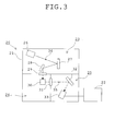
- FIG. 3 is an explanatory view showing the formation of a fluorescence spectrophotometer 20 which is the optical apparatus of the present invention.
- the fluorescence spectrophotometer 20 comprises a photometer 21, a control and / or analysis section 22, and a power source which is not shown in the drawings.
- the photometer 21 radiates excitation light 34 to a specimen and converts fluorescent light 35 emanating from the specimen into intensity signals.
- the control and / or analysis section 22 performs control of the photometer 21 and performs a display and / or an analysis of the measured intensity of the fluorescent light.
- the photometer 21 comprises an excitation light optical system 23, a specimen chamber 24, and a fluorescence optical system 25.
- the excitation light optical system 23 comprises a xenon lamp 26 emitting the excitation light 34, an excitation light diffraction grating 27 splitting the excitation light 34 into a spectrum, a mirror 28 changing the direction of the excitation light 34 toward the specimen, and an excitation light exit window 29 spatially dividing the excitation light optical system 23 form the specimen chamber 24.
- a low fluorescent optical glass of Embodiment 1 is used for the excitation light exit window 29.
- a fluorescence entrance window 31 spatially divides the fluorescence optical system 25 from the specimen chamber 24.
- the fluorescence optical system 25 comprises the light entrance window 31, a fluorescence diffraction grating 32, and a photomultiplier tube 33.
- the light entrance window 31 is provided at the position where the fluorescent light 35 emanating from a specimen 30 is incident on the fluorescence optical system 25.
- the fluorescence diffraction grating 32 splits the incident fluorescent light 35 into a spectrum.
- the photomultiplier tube 33 converts the intensity of the split fluorescent light into electric current.
- an optical glass of Embodiment 1 is used for the fluorescence entrance window 31.
- the specimen 30 the fluorescent light of which is measured is placed in the specimen chamber 24.
- the excitation light 34 emanating from the xenon lamp 26 is split into a spectrum by the excitation light diffraction grating 27 to form, for example, light with a center wavelength of 480 nm and a wavelength width of 10 nm.
- This excitation light is reflected by the mirror 28, passes through the excitation light exit window 29, and enters the specimen chamber 24 to be radiated to the specimen 30.
- the excitation light 34 which is radiated to the specimen 30, part of the excitation light 34 is absorbed by the specimen 30 and the fluorescent light is made to emanate from the specimen 30 by the energy of the absorbed excitation light 34.
- the fluorescent light 35 emanating from the specimen 30 passes through the fluorescence entrance window 31 and enters the fluorescence optical system 25.
- the fluorescent light 35 is split into a spectrum by the fluorescence diffraction grating 32 (for example, wavelength 600 nm).
- the fluorescence diffraction grating 32 is operated to change the angle of incidence of the fluorescent light 35 to the fluorescence diffraction grating 32. In this way, the wavelength of the light incident on the photomultiplier tube 33 is changed.
- auto-fluorescent light occurs in the excitation light exit window 29 through which the excitation light 34 is radiated.
- the scattered light of the excitation light 34 which is radiated to the specimen 30 is incident on the excitation light exit window 29 and the fluorescence entrance window 31 to cause auto-fluorescence light.
- Such auto-fluorescent light increases the value of the background in measurement and brings about difficulty in measurement requiring a high degree of accuracy, such as measurement of the feeble intensity of fluorescent light.
- an optical glass of Embodiment 1 is used for the excitation light exit window 29 and the fluorescence entrance window 31.
- the optical glass of the embodiment 5 is shown as the Test examples 1-20 in Table 3.
- twenty kinds of glass examples are prepared and an amount of fluorescent light of each of the glass examples was measured.
- each of the compositions shown in Table 3 is expressed by percentage by weight.
- a high-grade glass material in which an amount of mixed impurities is small is used for the optical glass of the present embodiment.
- this glass material is mixed so as to obtain a preset ratio, the mixed materials are melted at 1100-1400 °C in a platinum crucible for 2-5 hours and are annealed.
- the glass prepared in this way is worked into a square pillar of 11 ⁇ 11 ⁇ 40 mm, four faces (faces of 11 ⁇ 40 mm) in a longitudinal direction are finished by mirror polishing, and an optical glass is obtained.
- This optical glass is used and the fluorescence intensity is measured by the fluorescence spectrophotometer (FP-6500, made by JASCO Corporation).
- FP-6500 fluorescence spectrophotometer
- light of 480 nm is radiated to the optical glass of each of the embodiments to measure the fluorescence intensity in wavelengths of 500-700 nm.
- the value (an arbitrary unit) acquired by integrating the fluorescence intensity in wavelengths of 500-700 nm is taken as auto-fluorescence intensity, and is compared with the auto-fluorescence intensity of a commercial B 2 O 3 -La 2 O 3 based glass which is arbitrarily selected, in order to evaluate the optical glass.
- the auto-fluorescence intensity of the commercial glass is regarded as an evaluation criterion, the ratio of the auto-fluorescence intensity of each of the test examples in Table 3 to the auto-fluorescence intensity of the commercial glass is found, and a fluorescence degree is defined by the ratio.
- a fluorescence degree which is less than 0.7 is ranked as A
- a fluorescence degree which is 0.7-1.5 is ranked as B
- a fluorescence degree which is 1.5 or more is ranked as C.
- Table 4 shows results of evaluations of fluorescence degree on the basis of the results of measurements of auto-fluorescence intensity which is made in the same way with respect to three commercial optical glasses (, where a Sm content is not measured in the three commercial optical glasses), as a comparative example.
- Optical glasses of the commercial glasses 1 to 3 are a commercial B 2 O 3 -La 2 O 3 based glass which differs from the above-described B 2 O 3 -La 2 O 3 based glass for the evaluation criterion.
- the index of a fluorescence degree is A.
- an optical glass of the Embodiment 5 (one of optical glasses of the test examples 1-20) is used in a part of optical lenses used for the objective lens 8, and whereby, it is possible to reduce auto-fluorescent light occurring in the objective lens 8. As a result, the contrast of a fluorescent image increases and it is possible to obtain a sharp fluorescent image.
- an optical glass of the Embodiment 5 is used in a part of glasses which are used for the objective lens 8. And, auto-fluorescence intensity was measured without placing a specimen on the specimen stand 10. Also, auto-fluorescence intensity was measured in an objective lens 8 in which a conventional optical glass is used.
- the measurement value of the auto-fluorescence intensity (an arbitrary unit) is 1.4.
- the measurement value of the auto-fluorescence intensity (an arbitrary unit) is 3.0 in the case of the objective lens 8 in which the conventional optical glass is used.
- the auto-fluorescence intensity of the optical grass of the Embodiment 5 is about 1/2 of that of the conventional optical glass, as compared with the conventional glass.
- the optical glass of the Embodiment 5 makes it possible to make background noise smaller than background noise in a fluorescence microscope according to the prior art.
- a low fluorescent glass of the Embodiment 5 is used for the excitation light exit window 29, and an optical glass of the Embodiment 5 is used for the light entrance window 31, respectively.
- an optical apparatus of the present invention is not limited to the above embodiments, and in another optical apparatus in which an optical glass of the present embodiments is used, the same effects are brought about.
Landscapes
- Chemical & Material Sciences (AREA)
- Physics & Mathematics (AREA)
- Engineering & Computer Science (AREA)
- General Physics & Mathematics (AREA)
- Optics & Photonics (AREA)
- Life Sciences & Earth Sciences (AREA)
- Analytical Chemistry (AREA)
- Chemical Kinetics & Catalysis (AREA)
- General Chemical & Material Sciences (AREA)
- Geochemistry & Mineralogy (AREA)
- Materials Engineering (AREA)
- Organic Chemistry (AREA)
- Glass Compositions (AREA)
Abstract
Description
- This invention relates to an optical glass, and in particular, an optical glass used in an optical system for a fluorescence observation and a fluorescence intensity measurement, and an optical apparatus using this optical glass. In particular, this invention relates to an optical glass in which a Cr content or Sm content is reduced to the utmost, where Cr and Sm are elements which emit auto-fluorescent light.
- An observation of single-molecule fluorescence, a measurement of fluorescence intensity of a specimen having low fluorescence intensity, and so on require a highly accurate apparatus for an observation or a measurement in use of a fluorescence observation measurement apparatus such as a fluorescence microscope.
- Auto-fluorescent light from a glass used for a lens of an optical system has been known as one of the causes which deteriorate the accuracy of such apparatus in image observation or measurement.
- This auto-fluorescent light is fluorescent light which is emitted by a glass of a material for lens after the glass absorbs a part of excitation light when the excitation light passes through the lens to excite a specimen. This auto-fluorescence light makes a highly accurate observation difficult because a superposition of this auto-fluorescent light and fluorescent light which is emitted from a specimen causes loss of information about a dark portion of a fluorescence image. In fluorescence intensity measurement, the auto-fluorescent light becomes background noise and an accurate measurement for a specimen of low fluorescence intensity becomes difficult. The use of a glass the auto-fluorescence intensity of which is reduced makes it possible to carry out a highly accurate observation or measurement.
- Also, if ultraviolet light is used as excitation light in a case where a specimen is a living cell or the like in such a fluorescence observation and / or measurement, the living cell may be damaged. For this reason, for example, visible light with a wavelength of 480 nm is often used.
- The arts of a glass the auto-fluorescence intensity of which is reduced (, where the glass is called a low fluorescent glass hereinafter,) include an art of a glass in which an impurity content is reduced, as disclosed in Japanese patent Kokai No.
Hei 4-219342 Hei 11-106233 Hei 11-106233 - Japanese patent Kokai No.
Hei 4-219342 - Also, Japanese patent Kokai No.
Hei 11-106233 - However, a low fluorescent glass according to the conventional art is given countermeasures only against auto-fluorescent light in the case of radiation of ultraviolet rays (a wavelength less than 380 nm), and auto-fluorescent light in the case of radiation of visible light (wavelengths of 380 to 550 nm) is not taken into consideration at all. In addition, a low fluorescent glass according to the conventional art has a problem that it is impossible to sufficiently reduce auto-fluorescent light in the case of radiation of visible light.
- And, as mentioned above, a fluorescence microscope is used for an observation of an fluorescent image and measurement of the amount of fluorescent light. In order to favorably correct aberration, an optical glass of high-refractive index and low-dispersion property is also used for a lens of the optical system of the fluorescence microscope. The optical glass of high-refractive index and low-dispersion property, however, is liable to cause auto-fluorescent light. As a result, the fluorescence microscope using the optical glass of high-refractive index and low-dispersion property has the problem that the observation of an fluorescent image of high contrast and highly accurate measurement become difficult.
- The present invention is made in view of the above-described problems. The object of the present invention is to provide an optical glass the auto-fluorescence intensity of which is reduced more than that of a conventional glass in the case of radiation of visible light and is to provide an optical apparatus using this optical glass.
- In order to achieve the above object, an optical glass of the present invention is made in such a way that a Cr content is less than 5 ppm, with respect to a 100 % basic glass composition containing at least,
SiO2 2-10% B2O3 5-45 %, and La2O3 30-60 % - Also, an optical glass of the present invention is made in such a way that a Cr content is less than 5 ppm, with respect to a 100 % basic glass composition containing
SiO2 2-10 % B2O3 5-45 % La2O3 30-60 % RO (R = Zn, Sr, Ca, Ba) 0-15 % Ln2O3 (Ln = Y, Gd) 0-40 %, and ZrO2 + Nb2O5 + Ta2O5 0-30 % - Also, an optical glass of the present invention is made in such a way that a Cr content is less than 5 ppm, with respect to a 100 % basic glass composition containing at least,
SiO2 2-20 % B2O3 5-45 %, and La2O3 10-29 % - Also, an optical glass of the present invention is made in such a way that a Cr content is less than 5 ppm, with respect to a 100 % basic glass composition containing
SiO2 2-20 % B2O3 5-45 % La2O3 10-29 % RO (R = Zn, Sr, Ca, Ba) 0-45 % Ln2O3 (Ln = Y, Gd) 0-10 %, and ZrO2 + Nb2O5 + TiO2+ Ta2O5 1-20 % - Also, an optical glass of the present invention is made in such a way that a Cr content is less than 5 ppm, with respect to a 100 % basic glass composition containing at least,
SiO2 2-20 % B2O3 5-45 % La2O3 10-29% Al2O3 0.1-5% RO (R = Zn, Sr, Ca, Ba) 1-60% Ln2O3 (Ln = Y, Gd) 0-10 %, and ZrO2 + Nb2O5 + TiO2+ Ta2O5 1-10 % - Also, an optical glass of the present invention contains as a defoaming agent one or more of Sb2O3, chloride, sulfide, and fluoride, the content of which is 0.01 to 1 % by weight with respect to the above-described basic glass composition of 100%.
- Further, an optical glass of the present invention contains at least one or more of Li2O, Na2O, K2O, Rb2O, and Cs2O, the content of which is 0 to 10 % by weight.
- Also, an optical glass of the present invention is made in such a way that a Sm content is 3 ppm or less, with respect to a 100 % basic glass composition containing at least,
SiO2 2-10% B2O3 5-45 %, and La2O3 30-60 % - Also, an optical glass of the present invention is made in such a way that a Sm content is 3 ppm or less, with respect to a 100 % basic glass composition containing
SiO2 2-10 % B2O3 5-45 % La2O3 30-60 % RO (R = Zn, Sr, Ca, Ba) 0-15 % Ln2O3 (Ln = Y, Gd) 0-40 %, and ZrO2 + Nb2O5 + Ta2O5 0-30 % - Also, an optical glass of the present invention is made in such a way that a Sm content is 3 ppm or less, with respect to a 100 % basic glass composition containing at least,
SiO2 2-20 % B2O3 5-45 %, and La2O3 10-29 % - Also, an optical glass of the present invention is made in such a way that a Sm content is 3 ppm or less, with respect to a 100 % basic glass composition containing
SiO2 2-20 % B2O3 5-45 % La2O3 10-29 % RO (R = Zn, Sr, Ca, Ba) 0-45 % Ln2O3 (Ln = Y, Gd) 0-10 %, and ZrO2 + Nb2O5 + TiO2+ Ta2O5 1-20 % - Also, an optical glass of the present invention is made in such a way that a Sm content is 3 ppm or less, with respect to a 100 % basic glass composition containing at least,
SiO2 2-20 % B2O3 5-45 % La2O3 10-29 % Al2O3 0.1-5% RO (R = Zn, Sr, Ca, Ba) 1-60 % Ln2O3 (Ln = Y, Gd) 0-10 %, and ZrO2 + Nb2O5 + TiO2+ Ta2O5 1-10 % - Also, an optical glass of the present invention contains as a defoaming agent one or more of Sb2O3, chloride, sulfide, and fluoride, the content of which is 0.01 to 1 % by weight with respect to the above-described basic glass composition of 100%.
- Further, an optical glass of the present invention contains at least one or more of Li2O, Na2O, K2O, Rb2O, and Cs2O, the content of which is 0 to 10 % by weight.
- Also, an optical apparatus of the present invention is provided with an optical system having an optical glass which is mentioned above.
- According to an optical glass of the present invention, it is possible to realize an optical glass in which the auto-fluorescence intensity is reduced more than that of a conventional glass in the case of radiation of visible light and to realize an optical apparatus using this optical glass.
- Because a Cr content is particularly less than 5 ppm in an optical grass of the present invention, a glass the auto-fluorescence of which is weak can be obtained. And, because this glass has a small Cr content, the Cr content hardly affects the optical properties such as refractive index and dispersion, the chemical properties, the thermal properties and the mechanical properties in 400 to 700 nm which are used in a fluorescence image observation.
- As a result, it is unnecessary to carry out a design change of an optical system and changes of processes such as a mechanical working process and a coating process which relate to the chemical properties, the thermal properties and the mechanical properties, and it is possible to easily replace a conventional grass for an optical system with a low fluorescent glass of the present invention.
- Also, because a Sm content is particularly 3 ppm or less in an optical grass of the present invention, a glass the auto-fluorescence of which is weak can be obtained. And, because this glass has a small Sm content, the Sm content hardly affects the optical properties such as refractive index and dispersion, the chemical properties, the thermal properties and the mechanical properties in 400 to 700 nm which are used in a fluorescence image observation.
- As a result, it is unnecessary to carry out a design change of an optical system and changes of processes such as a mechanical working process and a coating process which relate to the chemical properties, the thermal properties and the mechanical properties, and it is possible to easily replace a conventional grass for an optical system with a low fluorescent glass of the present invention.
-
- [
Fig. 1] Fig. 1 is a sketchily explanatory view showing a fluorescence microscope which is one embodiment of an optical apparatus of the present invention. - [
Fig. 2] Fig. 2 is a sketchily explanatory view showing a fluorescence microscope of the present invention. - [
Fig. 3] Fig. 3 is an explanatory view showing the constituent of a fluorescence spectrophotometer of the present invention. - [
Fig. 4] Fig. 4 is a view showing the excitation spectrum of an excitation wavelength in Sm. - [
Fig. 5] Fig. 5 is a view showing the fluorescence spectrum of an emission wavelength in Sm. - As a result of making every research in order to achieve the above object, the present inventor found that it was possible to reduce auto-fluorescent light in radiation of visible light by making a Cr content of less than 5 ppm or a Sm content of 3 ppm or less in a B2O3-La2O3 based glass. In addition, the present inventor found that it was possible to reduce auto-fluorescent light in radiation of visible light by making a Sm content of 3 ppm or less.
- The present invention provides a B2O3-La2O3 based optical glass containing the constituents as described above. The role of each glass constituent and the reason for the determination of the optimum content of each of the constituents will be explained below.
- An optical glass of the first embodiment contains SiO2, B2O3, and La2O3 as a basic glass composition.
- SiO2 is one of constituents which are a glass network former. The optical glass of the present embodiment contains 2-10 % SiO2. In the case of the content less than 2 %, the chemical durability of the glass is degraded. On the other hand, in the case of the content more than 10 %, the stability of the glass is impaired and a tendency to crystallization of the glass becomes pronounced.
- B2O3 is one of constituents which are a glass network former. The optical glass of the present embodiment contains 5-45 % B2O3. In the case of the content less than 5 %, the stability and meltability of the glass are deteriorated. Also, in the case of the content more than 45 %, the chemical durability is degraded.
- La2O3 is a constituent for increasing the refractive index. The optical glass of the present embodiment contains 30-60 % La2O3. In the case of the content less than 30 %, a desired refractive index is not obtained in the present embodiment. On the other hand, in the case of the content more than 60 %, the stability of the glass is impaired.
- The optical glass of the second embodiment contains at least one of RO, Ln2O3, ZrO2, Nb2O5, and Ta2O5, in addition to the three constituents mentioned above, as a basic glass composition.
- In RO, R = Zn, Sr, Ca, or Ba, and RO indicates ZnO, SrO, CaO, or BaO. RO is a constituent for adjusting the refractive index and stability of the glass. Particularly, BaO is a constituent which considerably contributes to a high refractive index of the glass. In addition, the other constituents contribute to improvement in the stability of the glass, together with an adjustment of the refractive index of the glass. The optical glass of the present embodiment contains 0-15 % RO (R = Zn, Sr, Ca, or Ba). In the case of the content more than 15 %, the stability and / or chemical durability of the glass is impaired. When the optical glass of the present embodiment contains Ro, the optical glass of the present embodiment has only to contain at least one of ZnO, SrO, CaO, and BaO.
- In Ln2O3, Ln = Y, or Gd, and Ln2O3 indicates Y2O3 or Gd2O3. Y2O3 and Gd2O3 are constituents for increasing the refractive index and for adjusting a dispersion value. The optical glass of the present embodiment contains 0-40 % Ln2O3 (Ln = Y or Gd). In the case of the content more than 40 %, the stability of the glass is impaired and the tendency to crystallization becomes pronounced. When the optical glass of the present embodiment contains Ln2O3, the optical glass of the present embodiment has only to contain at least one of Y2O3 and Gd2O3.
- ZrO2, Nb2O5, TiO2, and Ta2O5 are constituents for increasing the refractive index and for adjusting the dispersion value. The optical glass of the present embodiment contains 0-30 % ZrO2 + Nb2O5 + Ta2O5. In the case of the content more than 30 %, the meltability is deteriorated and the stability of the glass is also impaired. When the optical glass of the present embodiment contains ZrO2, Nb2O5, and / or Ta2O5, the optical glass of the present embodiment has only to contain at least one of ZrO2, Nb2O5, and Ta2O5.
- An optical glass of the third embodiment differs from the optical glass of the first embodiment in percentage of each of the constituents. That is to say, the optical glass contains 2-20 % SiO2, 5-45 % B2O3, and 10-29 % La2O3. In the optical glass of the third embodiment, the upper limit value of a SiO2 content is 20 % and is larger than that of the optical glass of the first embodiment. On the other hand, a La2O3 content is 10-29 % in the third embodiment and is smaller than that of the optical glass of the first embodiment.
- Also, an optical glass of the fourth embodiment contains at least one of RO, Ln2O3, ZrO2, Nb2O5, TiO2, and Ta2O5, in addition to the three constituents mentioned above in the third embodiment, as a basic glass composition. That is to say, the optical glass of the fourth embodiment contains 0-45 % RO (R = Zn, Sr, Ca, or Ba), 0-10 % Ln2O3 (Ln = Y, or Gd), and 1-20 % ZrO2 + Nb2O5 + TiO2, + Ta2O5. The optical glass of the fourth embodiment may not contain RO and Ln2O3.
- Also, an optical glass of the fifth embodiment contains Al2O3, in addition to the three constituents in the fourth embodiment, as a basic glass composition. In addition, the optical glass of the fifth embodiment contains RO and at least one of ZrO2, Nb2O5, TiO2, and Ta2O5. That is to say, the optical glass of the fifth embodiment contains 0.1-5 % Al2O3, 1-60 % RO (R = Zn, Sr, Ca, or Ba), and 1-10 % ZrO2 + Nb2O5 + TiO2, + Ta2O5. Also, the optical glass of the fifth embodiment contains 0-10 % Ln2O3 (Ln = Y, or Gd) or may not contain Ln2O3.
- Al2O3 is a constituent for adjusting the viscosity and weatherability of the glass in addition to adjusting the refractive index of the glass. In the case of the content more than 5 %, the stability and meltability of the glass are deteriorated.
- The function of each of the other constituents, or the like, is explained as in the first and second embodiments.
- A Cr content is less than 5 ppm or a Sm content is 3 ppm or less with respect to the 100 % basic glass compositions described above in the optical glasses of the first to fifth embodiments.
- Cr is a constituent emitting auto-fluorescent light. Cr emits fluorescent light having a peak wavelength of 545nm and auto-fluorescent light having a peak wavelength in the vicinity of 700 nm. Particularly, the latter auto-fluorescent light is widely observed in the region of wavelengths which are 650 nm or more, and the auto-fluorescence is highly sensitive to the Cr content. As a result, Cr is a constituent which causes an obstacle to highly accurate fluorescence observation and measurement in the near infrared region. If a Cr content is beyond 5 ppm, it is impossible to achieve the object of the present invention. Accordingly, it is preferred that a Cr content is less than 5 ppm. It is particularly preferred that a Cr content is 2 ppm or less.
- Sm is a constituent emitting auto-fluorescent light in radiation of light from ultraviolet region to visible region (200-500 nm).
Figs. 4 and 5 show the excitation spectrum and the fluorescence spectrum of Sm, respectively. In this case,Fig. 4 shows the excitation spectrum andFig. 5 shows the fluorescence spectrum. -
Fig. 4 is a view in which a fluorescence intensity of the fluorescence wavelength of 610 nm is plotted as an excitation wavelength is made to vary from 200 nm to 500 nm. For example, the fluorescence intensity in 610 nm is at a maximum when excitation light of 405 nm is radiated. On the other hand,Fig. 5 is a view in which a fluorescence intensity is shown per wavelength (550-700 nm) when an excitation wavelength is 405 nm. When one of wavelengths from 200 to 500 nm is selected as an excitation wavelength, excitation light with the excitation wavelength has a intensity proportional to the excitation spectrum shown inFig. 4 , and the excitation light causes fluorescent light which has a spectral shape which is similar to the fluorescent spectrum shown inFig. 5 . - As shown in
Fig. 4 , when light of 200-500 nm is radiated, Sm emits auto-fluorescent light of 550-700 nm. As a result, for example, when a fluorescent wavelength of a specimen is 550-700 nm, auto-fluorescent light generated by Sm is added to fluorescent light generated by the specimen. In this case, it is impossible to acquire a fluorescent image of the specimen with good contrast. If an amount of Sm which is contained in the glass is beyond 3 ppm, the auto-fluorescence has a bad influence on contrast of a fluorescent image. That is to say, if an amount of Sm which is contained in the glass is beyond 3ppm, it is impossible to acquire an optical glass in which the auto-fluorescence intensity is reduced. - Next, an optical glass of the sixth embodiment is described. The optical glass of the sixth embodiment contains as a defoaming agent one or more of Sb2O3, chloride, sulfide, and fluoride, where the one or more of Sb2O3, chloride, sulfide, and fluoride are added to one of the optical glasses of the first to fifth embodiments and the content of one or more of the constituents is 0.01 to 1 %. Such a manner makes it possible to decrease foam which is caused by raw materials resolving and / or reacting in melting a glass. In the case of the content less than 0.01 %, it is impossible to acquire a deforming effect. On the other hand, the content the more than 1 % causes a problem that auto-fluorescent light increases.
- Next, an optical glass of the seventh embodiment is described. The optical glass of the seventh embodiment contains at least one or more of Li2O, Na2O, K2O, Rb2O, and Cs2O which are an alkaline metal oxide, where the one or more of these alkaline metal oxides are added to one of the optical glasses of the first to sixth embodiments and the content of the one or more of the constituents is 0 to 10 %. Such a manner makes it possible to improve the meltability of the glass. In the case of the content more than 10 %, the chemical durability and the stability of the glass are degraded. Besides, it is preferred that the optical glass contains more than one alkaline metal oxide.
- Also, the optical glass of the present embodiment can contain another constituent for the purpose of improvements on the defoaming ability, meltability, and / or stability and so on.
- Subsequently, a fluorescence observation measurement apparatus of the present invention will be explained.
- An optical apparatus of the present invention refers to, for example, a fluorescence microscope, a living cell observation apparatus, a gene analysis apparatus, a photoluminescence measurement apparatus, a fluorescence spectrophotometer, a fluorescence life measurement apparatus, a plasma display panel examination apparatus, an endoscope having a fluorescence observation function, or the like. In any case, an optical apparatus of the present invention is an apparatus for observing or measuring fluorescent light.
- These optical apparatuses are an apparatus for observing and / or measuring fluorescent light emanating from a specimen. In order to make a specimen emit fluorescent light, excitation light emanating from a light source is radiated to the specimen through an optical system. By the irradiation of excitation light, the specimen emits fluorescent light. The fluorescent light is detected by a photodetector (such as a photodiode, photomultiplier tube, CCD, or CMOS), through an optical system.
- The optical system mentioned above contains optical parts, such as a lens, a prism, a mirror, a filter, etc., which are made of optical glass. The use of the optical glass of the present embodiment for each of these optical parts makes it possible to lower the intensity (the amount of light) of auto-fluorescent light emanating from each of the optical parts. As a result, in a fluorescence observation, a decrease in contrast of a fluorescent image can be suppressed. Moreover, in a fluorescence measurement, a noise component (auto-fluorescent light) in a fluorescence signal can be reduced.
- Subsequently, the optical glass of the
embodiment 1 is shown as Test examples 1-20 in Table 1. In theembodiment 1, twenty kinds of glass examples are prepared and an amount of fluorescent light of each of the glass examples is measured. Besides, each of compositions shown in Table 1 is expressed by percentage by weight. - A glass material which is used for the optical glass of the present embodiment is a high-grade glass material in which an amount of mixed impurities is small. After this glass material is mixed so as to obtain a preset ratio, the mixed materials are melted at 1100-1400 °C in a platinum crucible for 2-5 hours and are annealed. The glass prepared in this way is worked into a square pillar of 11 × 11 × 40 mm, four faces (faces of 11 × 40 mm) in a longitudinal direction are finished by mirror polishing, and an optical glass are obtained.
- This optical glass is used and the fluorescence intensity is measured by the fluorescence spectrophotometer (FP-6500, made by JASCO Corporation). In the measurement, light of 480 nm is radiated to the optical glass of each of the embodiments to measure the fluorescence intensity in wavelengths of 530-650 nm. The value (an arbitrary unit) acquired by integrating the fluorescence intensity in the wavelengths of 530-650 nm is taken as auto-fluorescence intensity, and is compared with the auto-fluorescence intensity of a commercial B2O3-La2O3 based glass which is arbitrarily selected, in order to evaluate the optical glass. In evaluation, the auto-fluorescence intensity of the commercial glass is regarded as an evaluation criterion, the ratio of the auto-fluorescence intensity of each of the test examples in Table 1 to the auto-fluorescence intensity of the commercial glass is found, and a fluorescence degree is defined by the ratio. A fluorescence degree which is less than 0.7 is ranked as A, a fluorescence degree which is 0.7-1.5 is ranked as B, and a fluorescence degree which is 1.5 or more is ranked as C.
- Also, Table 2 shows results of evaluations of fluorescence degree on the basis of the results of measurements of auto-fluorescence intensity which are made in the same way with respect to two commercial optical glasses (, where Cr contents are not measured in the two commercial glasses), as a comparative example. Optical glasses of the
commercial glasses - In order to achieve the object of the present invention, it is desired that the index of a fluorescence degree is A.
- These results confirm that the auto-fluorescence intensities are reduced more in the optical glasses of the present embodiment as compared with the optical glasses of the comparative examples.
- Besides, the correspondences between the test examples and the embodiments are as shown below.
- First embodiment: Test examples 1-10
- Second embodiment: Test examples 1-10
- Third embodiment: Test examples 11-20
- Fourth embodiment: Test examples 12, and 14-20
- Fifth embodiment: Test examples 18 and 20
- Sixth embodiment: Test examples 3, 4, 8-10, 14-16, 19 and 20
- Seventh embodiment: Test examples 1-20
- Subsequently, one embodiment of an optical apparatus of the present invention will be explained in accordance with
Fig. 1. Fig. 1 is an explanatory view showing schematically afluorescence microscope 1 which is an optical apparatus of the present invention. Thefluorescence microscope 1 comprises an excitationlight source section 2, an excitation lightoptical system 3, afilter section 4, an ocularoptical system 5, animage capturing section 6, adisplay device 7, anobjective lens 8, and aspecimen stand 10. Also,reference numeral 9 represents a specimen (a sample). - The excitation
light source section 2 is provided with a xenon lamp emittingexcitation light 11 and a power source device which is not shown in the drawings. The excitation lightoptical system 3 is an optical system which conducts theexcitation light 11 to thespecimen 9, and the excitation lightoptical system 3 is arranged between the excitationlight source section 2 and thefilter section 4. Thefilter section 4 is constructed with a dielectric multilayer film filter. Thefilter section 4 comprises a band-pass filter and a dichroic mirror. The dichroic mirror has properties of reflecting theexcitation light 11 and of transmittingfluorescent light 12. - The ocular
optical system 5 is an optical system for observing the image (the fluorescent image) of thespecimen 9 with a naked eye. Theimage capturing section 6 is a CCD camera capturing the image of thefluorescent light 12. Thedisplay device 7 displays the captured image of thefluorescent light 12. Theobjective lens 8 focuses theexcitation light 11 on thespecimen 9 and focuses thefluorescent light 12 on a preset position to form an image. The specimen stand 10 is used for placing thespecimen 9 thereon. - Light emitted from the excitation
light source section 2 passes through the excitation lightoptical system 3 and is incident on thefilter section 4. A band-pass filter is arranged in thefilter section 4, and the band-pass filter transmits light of wavelengths of 460-495 nm. Hence, the light emitted from the excitationlight source section 2 passes through thefilter section 4 and thereby the light of wavelengths of 460-495 nm, or theexcitation light 11, is obtained. - Next, the
excitation light 11 is incident on the dichroic mirror. The dichroic mirror has properties of reflecting light of wavelengths of less than 505 nm and of transmitting light of wavelength of more than 505 nm. The dichroic mirror is provided at an angle of 45 degrees to the traveling direction of theexcitation light 11. As a result, theexcitation light 11 incident on the dichroic mirror is bent at an angle of 90 degrees and is led to theobjective lens 8. - The
excitation light 11 is collected by theobjective lens 8 to be radiated to thespecimen 9 which is provided on thespecimen stand 10. Theexcitation light 11 is absorbed by the specimen 9 (a fluorescent material), and thefluorescent light 12 emanates from thespecimen 9. - The
fluorescent light 12 is collected by theobjective lens 8. Thefluorescent light 12 thus collected is incident on the dichroic mirror of thefilter section 4. Here, the wavelength of thefluorescent light 12 is longer than 505 nm. Consequently, thefluorescent light 12 is transmitted through the dichroic mirror. Further, thefluorescent light 12, after passing through a filter transmitting light of wavelength longer than 510 nm, is focused on a preset position to form a fluorescent image. And, the image of this fluorescent light is observed by the ocularoptical system 5. - Also, the
fluorescence microscope 1 may be provided with an optical path switching mechanism (not shown in the drawings). The optical path is switched by the optical path switching mechanism and thereby thefluorescent light 12 can be led to theimage capturing section 6. In this way, a fluorescent image can be captured by theimage capturing section 6. The fluorescent image thus captured is displayed on thedisplay device 7. - In the present embodiment, auto-fluorescent light which becomes a noise occurs in the
filter section 4 and theobjective lens 8. In the present embodiment, an optical glass of Embodiment 1 (one of the optical glasses of the Test examples 1-20) is used for a part of optical lenses used in theobjective lens 8. Whereby, auto-fluorescence light occurring in theobjective lens 8 can be reduced. As a result, the contrast of the fluorescent image is increased and a sharp fluorescent image can be obtained. - Subsequently, another embodiment of the optical apparatus of the present invention will be explained in accordance with
Fig. 2. Fig. 2 is an explanatory view showing schematically afluorescence microscope 13 which is an optical apparatus of the present invention. Thefluorescence microscope 13 has no difference from thefluorescence microscope 1 shown inFig. 1 with the exception that theimage capturing section 6 is replaced with aphotodetector section 14, and thus its detailed description is omitted. Besides, thephotodetector section 14 is provided with a photomultiplier tube measuring the intensity of thefluorescent light 12 and with a power device which is not shown in the drawings. - The
fluorescent light 12 is transmitted through the dichroic mirror of thefilter section 4 and passes through the filter transmitting light of wavelength longer than 420 nm. And, thefluorescent light 12 is then incident on thephotodetector section 14. In thephotodetector section 14, the intensity of the light (the fluorescent light intensity) is measured as a current value, and the value is displayed on adisplay device 15. - In this case, auto-fluorescent light which becomes noise occurs in the
filter section 4 and theobjective lens 8. Here, when measurement of fluorescent light intensity is carried out without placing thespecimen 9 on thespecimen stand 10, auto-fluorescent light occurring in thefilter section 4 and theobjective lens 8 is measured. - In the present embodiment, an optical glass of
Embodiment 1 is used for a part of glasses which are used for theobjective lens 8. And, measurement of fluorescent light intensity was done without placing the specimen on thespecimen stand 10. In addition, theobjective lens 8 using a conventional optical glass was used to make measurement of fluorescent light intensity. - As a result, in the case of the
objective lens 8 using the optical glass ofEmbodiment 1, the measured value of the fluorescent light intensity (an arbitrary unit) is 63. In contrast to this, the measured value of the fluorescent light intensity (an arbitrary unit) is 260 in the case of theobjective lens 8 using the conventional optical glass. In this way, the intensity of the auto-fluorescent light is reduced to about 1/4 in the optical glass ofEmbodiment 1, as compared with the conventional one. Hence, it is possible to make background noise smaller in the fluorescence microscope of the present embodiment than in the fluorescence microscope of the prior art. - Subsequently, still another embodiment of an optical apparatus of the present invention will be explained in accordance with
Fig. 3. Fig. 3 is an explanatory view showing the formation of afluorescence spectrophotometer 20 which is the optical apparatus of the present invention. Thefluorescence spectrophotometer 20 comprises aphotometer 21, a control and / oranalysis section 22, and a power source which is not shown in the drawings. - The
photometer 21 radiatesexcitation light 34 to a specimen and converts fluorescent light 35 emanating from the specimen into intensity signals. The control and / oranalysis section 22 performs control of thephotometer 21 and performs a display and / or an analysis of the measured intensity of the fluorescent light. - The
photometer 21 comprises an excitation lightoptical system 23, aspecimen chamber 24, and a fluorescenceoptical system 25. The excitation lightoptical system 23 comprises axenon lamp 26 emitting theexcitation light 34, an excitationlight diffraction grating 27 splitting theexcitation light 34 into a spectrum, amirror 28 changing the direction of theexcitation light 34 toward the specimen, and an excitationlight exit window 29 spatially dividing the excitation lightoptical system 23 form thespecimen chamber 24. A low fluorescent optical glass ofEmbodiment 1 is used for the excitationlight exit window 29. - The reason for spatially dividing the excitation light
optical system 23 from thespecimen chamber 24 is to prevent the contamination of the excitation lightoptical system 23 caused by the penetration of a foreign matter from thespecimen chamber 24. For the same reason, also in the fluorescenceoptical system 25 described later, afluorescence entrance window 31 spatially divides the fluorescenceoptical system 25 from thespecimen chamber 24. - The fluorescence
optical system 25 comprises thelight entrance window 31, afluorescence diffraction grating 32, and aphotomultiplier tube 33. Thelight entrance window 31 is provided at the position where the fluorescent light 35 emanating from aspecimen 30 is incident on the fluorescenceoptical system 25. Thefluorescence diffraction grating 32 splits the incident fluorescent light 35 into a spectrum. Thephotomultiplier tube 33 converts the intensity of the split fluorescent light into electric current. Here, an optical glass ofEmbodiment 1 is used for thefluorescence entrance window 31. - Next, the measurement of fluorescent light with the
fluorescence spectrophotometer 20 will be explained. Thespecimen 30 the fluorescent light of which is measured is placed in thespecimen chamber 24. Theexcitation light 34 emanating from thexenon lamp 26 is split into a spectrum by the excitationlight diffraction grating 27 to form, for example, light with a center wavelength of 480 nm and a wavelength width of 10 nm. This excitation light is reflected by themirror 28, passes through the excitationlight exit window 29, and enters thespecimen chamber 24 to be radiated to thespecimen 30. - In the
excitation light 34 which is radiated to thespecimen 30, part of theexcitation light 34 is absorbed by thespecimen 30 and the fluorescent light is made to emanate from thespecimen 30 by the energy of the absorbedexcitation light 34. The fluorescent light 35 emanating from thespecimen 30 passes through thefluorescence entrance window 31 and enters the fluorescenceoptical system 25. Thefluorescent light 35 is split into a spectrum by the fluorescence diffraction grating 32 (for example,wavelength 600 nm). In splitting thefluorescent light 35 into a spectrum, thefluorescence diffraction grating 32 is operated to change the angle of incidence of thefluorescent light 35 to thefluorescence diffraction grating 32. In this way, the wavelength of the light incident on thephotomultiplier tube 33 is changed. - Light into which the
fluorescence diffraction grating 32 split thefluorescent light 35 is incident on thephotomultiplier tube 33 so that the intensity of the light is converted into electric current. The intensity of the light converted into the electric current by thephotomultiplier tube 33 is displayed and / or analyzed by the control and / oranalysis section 22. When the data of the intensity of the fluorescent light are collected per wavelength, the fluorescent light spectrum expressing the intensity of the fluorescent light with respect to the wavelengths of the fluorescent light is obtained. - In a fluorescence spectrophotometer of the prior art, auto-fluorescent light occurs in the excitation
light exit window 29 through which theexcitation light 34 is radiated. In addition, the scattered light of theexcitation light 34 which is radiated to thespecimen 30 is incident on the excitationlight exit window 29 and thefluorescence entrance window 31 to cause auto-fluorescence light. Such auto-fluorescent light increases the value of the background in measurement and brings about difficulty in measurement requiring a high degree of accuracy, such as measurement of the feeble intensity of fluorescent light. - In contrast to this, in the
fluorescence spectrophotometer 20 according to the present embodiment, an optical glass ofEmbodiment 1 is used for the excitationlight exit window 29 and thefluorescence entrance window 31. Whereby, it is possible to make a small intensity of auto-fluorescence light occurring from these windows. Hence, it is possible to lower the value of the background of measurement. Consequently, even though fluorescent light has a feeble intensity, it is possible to make measurement of the fluorescent light with a high degree of accuracy. - Subsequently, the optical glass of the
embodiment 5 is shown as the Test examples 1-20 in Table 3. In theembodiment 5, twenty kinds of glass examples are prepared and an amount of fluorescent light of each of the glass examples was measured. Besides, each of the compositions shown in Table 3 is expressed by percentage by weight. - A high-grade glass material in which an amount of mixed impurities is small is used for the optical glass of the present embodiment. After this glass material is mixed so as to obtain a preset ratio, the mixed materials are melted at 1100-1400 °C in a platinum crucible for 2-5 hours and are annealed. The glass prepared in this way is worked into a square pillar of 11 × 11 × 40 mm, four faces (faces of 11 × 40 mm) in a longitudinal direction are finished by mirror polishing, and an optical glass is obtained.
- This optical glass is used and the fluorescence intensity is measured by the fluorescence spectrophotometer (FP-6500, made by JASCO Corporation). In the measurement, light of 480 nm is radiated to the optical glass of each of the embodiments to measure the fluorescence intensity in wavelengths of 500-700 nm. And, the value (an arbitrary unit) acquired by integrating the fluorescence intensity in wavelengths of 500-700 nm is taken as auto-fluorescence intensity, and is compared with the auto-fluorescence intensity of a commercial B2O3-La2O3 based glass which is arbitrarily selected, in order to evaluate the optical glass. In evaluation, the auto-fluorescence intensity of the commercial glass is regarded as an evaluation criterion, the ratio of the auto-fluorescence intensity of each of the test examples in Table 3 to the auto-fluorescence intensity of the commercial glass is found, and a fluorescence degree is defined by the ratio. A fluorescence degree which is less than 0.7 is ranked as A, a fluorescence degree which is 0.7-1.5 is ranked as B, and a fluorescence degree which is 1.5 or more is ranked as C.
- Also, Table 4 shows results of evaluations of fluorescence degree on the basis of the results of measurements of auto-fluorescence intensity which is made in the same way with respect to three commercial optical glasses (, where a Sm content is not measured in the three commercial optical glasses), as a comparative example. Optical glasses of the
commercial glasses 1 to 3 are a commercial B2O3-La2O3 based glass which differs from the above-described B2O3-La2O3 based glass for the evaluation criterion. - In order to achieve the object of the present invention, it is desired that the index of a fluorescence degree is A.
- These results confirm that the auto-fluorescence intensities are reduced more in the optical glasses of the present embodiment as compared with the optical glasses of the comparative examples.


[Table 4] Comparative example The commercial glass 1The commercial glass 2The commercial glass 3Fluorescent degree B C B - Because the constitution and operation effect of the present embodiment are the same as those of the embodiment which are explained by referring to
Fig. 1 , respectively, the explanations of the constitution and operation effect of the present embodiment are omitted. In the present embodiment, an optical glass of the Embodiment 5 (one of optical glasses of the test examples 1-20) is used in a part of optical lenses used for theobjective lens 8, and whereby, it is possible to reduce auto-fluorescent light occurring in theobjective lens 8. As a result, the contrast of a fluorescent image increases and it is possible to obtain a sharp fluorescent image. - Because the constitution and operation effect of the present embodiment are the same as those of the embodiment which are explained by referring to
Fig. 2 , respectively, the explanations of the constitution and operation effect of the present embodiment are omitted. In the present embodiment, an optical glass of theEmbodiment 5 is used in a part of glasses which are used for theobjective lens 8. And, auto-fluorescence intensity was measured without placing a specimen on thespecimen stand 10. Also, auto-fluorescence intensity was measured in anobjective lens 8 in which a conventional optical glass is used. - As a result, in the case of the
objective lens 8 in which the optical glass of theEmbodiment 5 is used, the measurement value of the auto-fluorescence intensity (an arbitrary unit) is 1.4. In contrast to the case, the measurement value of the auto-fluorescence intensity (an arbitrary unit) is 3.0 in the case of theobjective lens 8 in which the conventional optical glass is used. Thus, the auto-fluorescence intensity of the optical grass of theEmbodiment 5 is about 1/2 of that of the conventional optical glass, as compared with the conventional glass. For this reason, the optical glass of theEmbodiment 5 makes it possible to make background noise smaller than background noise in a fluorescence microscope according to the prior art. - Because the constitution and operation effect of the present embodiment are the same as those of the embodiment which are explained by referring to
Fig. 3 , respectively, the explanations of the constitution and operation effect of the present embodiment are omitted. However, a low fluorescent glass of theEmbodiment 5 is used for the excitationlight exit window 29, and an optical glass of theEmbodiment 5 is used for thelight entrance window 31, respectively. - Besides, an optical apparatus of the present invention is not limited to the above embodiments, and in another optical apparatus in which an optical glass of the present embodiments is used, the same effects are brought about.


| Comparative example | ||
| The | The | |
| Fluorescent degree | | B |
Claims (15)
- An optical glass characterized in that a Cr content is less than 5 ppm with respect to a 100 % basic glass composition containing at least,
SiO2 2-10 % B2O3 5-45 %, and La2O3 30-60 % - An optical glass characterized in that a Cr content is less than 5 ppm with respect to a 100 % basic glass composition containing
SiO2 2-10 % B2O3 5-45 % La2O3 30-60 % RO (R = Zn, Sr, Ca, Ba) 0-15 % Ln2O3 (Ln = Y, Gd) 0-40 %, and ZrO2 + Nb2O5 + Ta2O5 0-30 % - An optical glass characterized in that a Cr content is less than 5 ppm with respect to a 100 % basic glass composition containing at least,
SiO2 2-20 % B2O3 5-45 %, and La2O3 10-29 % - An optical glass characterized in that a Cr content is less than 5 ppm with respect to a 100 % basic glass composition containing
SiO2 2-20 % B2O3 5-45 % La2O3 10-29 % RO (R = Zn, Sr, Ca, Ba) 0-45 % Ln2O3 (Ln = Y, Gd) 0-10 %, and ZrO2 + Nb2O5 + TiO2+ Ta2O5 1-20 % - An an optical glass characterized in that a Cr content is less than 5 ppm with respect to a 100 % basic glass composition containing
SiO2 2-20 % B2O3 5-45 % La2O3 10-29 % Al2O3 0.1-5 % RO (R = Zn, Sr, Ca, Ba) 1-60 % Ln2O3 (Ln = Y, Gd) 0-10 %, and ZrO2 + Nb2O5 + TiO2+ Ta2O5 1-10 % - An optical glass according to claims 1 to 5, characterized in that the optical glass contains as a defoaming agent one or more of Sb2O3, chloride, sulfide, and fluoride, the content of which is 0.01 to 1 % by weight with respect to the basic glass composition of 100 %.
- An optical glass according to claims 1 to 6, characterized in that the optical glass contains at least one or more of Li2O, Na2O, K2O, Rb2O, and Cs2O, the content of which is 0 to 10 % by weight.
- An optical glass characterized in that a Sm content is 3 ppm or less with respect to a 100 % basic glass composition containing at least,
SiO2 2-10 % B2O3 5-45 %, and La2O3 30-60 % - An optical glass characterized in that a Sm content is 3 ppm or less with respect to a 100 % basic glass composition containing
SiO2 2-10% B2O3 5-45 % La2O3 30-60 % RO (R = Zn, Sr, Ca, Ba) 0-15 % Ln2O3 (Ln = Y, Gd) 0-40 %, and ZrO2 + Nb2O5 + Ta2O5 0-30 % - An optical glass characterized in that a Sm content is 3 ppm or less with respect to a 100 % basic glass composition containing at least,
SiO2 2-20 % B2O3 5-45 %, and La2O3 10-29 % - An optical glass characterized in that a Sm content is 3 ppm or less with respect to a 100 % basic glass composition containing
SiO2 2-20 % B2O3 5-45 % La2O3 10-29 % RO (R = Zn, Sr, Ca, Ba) 0-45 % Ln2O3 (Ln = Y, Gd) 0-10 %, and ZrO2 + Nb2O5 + TiO2+ Ta2O5 1-20 % - An optical glass characterized in that a Sm content is 3 ppm or less with respect to a 100 % basic glass composition containing
SiO2 2-20 % B2O3 5-45 % La2O3 10-29 % Al2O3 0.1-5 % RO (R = Zn, Sr, Ca, Ba) 1-60 % Ln2O3 (Ln = Y, Gd) 0-10 %, and ZrO2 + Nb2O5 + TiO2+ Ta2O5 1-10 % - An optical glass according to claims 8 to 12, characterized in that the optical glass contains as a defoaming agent one or more of Sb2O3, chloride, sulfide, and fluoride, the content of which is 0.01 to 1 % by weight with respect to the above-described basic glass composition of 100 %.
- An optical glass according to claims 8 to 13, characterized in that the optical glass contains at least one or more of Li2O, Na2O, K2O, Rb2O, and Cs2O, the content of which is 0 to 10 % by weight.
- An optical apparatus characterized in that the optical apparatus is provided with an optical system having an optical glass which is described in one of claims 1 to 14.
Applications Claiming Priority (3)
| Application Number | Priority Date | Filing Date | Title |
|---|---|---|---|
| JP2007319941A JP2009143738A (en) | 2007-12-11 | 2007-12-11 | Optical glass and optical device using the same |
| JP2007319942A JP2009143739A (en) | 2007-12-11 | 2007-12-11 | Optical glass and optical device using the same |
| PCT/JP2008/072510 WO2009075325A1 (en) | 2007-12-11 | 2008-12-11 | Optical glass and optical device using the same |
Publications (2)
| Publication Number | Publication Date |
|---|---|
| EP2233446A1 true EP2233446A1 (en) | 2010-09-29 |
| EP2233446A4 EP2233446A4 (en) | 2015-02-18 |
Family
ID=40755564
Family Applications (1)
| Application Number | Title | Priority Date | Filing Date |
|---|---|---|---|
| EP08859090.6A Withdrawn EP2233446A4 (en) | 2007-12-11 | 2008-12-11 | Optical glass and optical device using the same |
Country Status (4)
| Country | Link |
|---|---|
| US (1) | US8372768B2 (en) |
| EP (1) | EP2233446A4 (en) |
| CN (1) | CN101896437A (en) |
| WO (1) | WO2009075325A1 (en) |
Families Citing this family (7)
| Publication number | Priority date | Publication date | Assignee | Title |
|---|---|---|---|---|
| JP2008280235A (en) * | 2007-04-09 | 2008-11-20 | Olympus Corp | Optical glass and optical device using the same |
| EP2595206A4 (en) | 2010-07-12 | 2016-01-13 | Univ Nagoya Nat Univ Corp | BROADBAND INFRARED TRANSMITTER |
| US9206074B2 (en) * | 2010-12-08 | 2015-12-08 | Nippon Electric Glass Co., Ltd. | High-refractive-index glass |
| CN102311229A (en) * | 2011-09-07 | 2012-01-11 | 成都光明光电股份有限公司 | Optical glass and optical element |
| CN107043210B (en) * | 2017-05-15 | 2019-12-17 | 湖北戈碧迦光电科技股份有限公司 | H-ZF72 optical glass and its preparation method |
| KR102752872B1 (en) | 2018-11-26 | 2025-01-09 | 오웬스 코닝 인텔렉츄얼 캐피탈 엘엘씨 | High-performance fiberglass compositions having improved elastic modulus |
| EP3887328A2 (en) | 2018-11-26 | 2021-10-06 | Owens Corning Intellectual Capital, LLC | High performance fiberglass composition with improved specific modulus |
Family Cites Families (16)
| Publication number | Priority date | Publication date | Assignee | Title |
|---|---|---|---|---|
| JPS553329A (en) * | 1978-06-21 | 1980-01-11 | Ohara Inc | Optical glass |
| JPH0393645A (en) * | 1989-09-01 | 1991-04-18 | Minolta Camera Co Ltd | Ultraviolet ray transmitting glass |
| JPH0393648A (en) | 1989-09-01 | 1991-04-18 | Minolta Camera Co Ltd | Ultraviolet ray transmitting glass |
| JP3043076B2 (en) | 1990-12-17 | 2000-05-22 | ホーヤ株式会社 | Low fluorescent glass |
| JPH11106233A (en) | 1997-10-03 | 1999-04-20 | Nikon Corp | Low fluorescent optical glass and method for producing the same |
| US6187702B1 (en) * | 1998-10-02 | 2001-02-13 | Kabushiki Kaisha Ohara | Ophthalmic and optical glasses |
| JP2002128539A (en) * | 2000-10-13 | 2002-05-09 | Ohara Inc | Low fluorescent optical glass |
| EP1496025A4 (en) * | 2002-03-29 | 2008-04-30 | Matsushita Electric Industrial Co Ltd | BISMUTH GLASS COMPOSITION, AND MAGNETIC HEAD AND PLASMA DISPLAY CONTAINING SAID COMPOSITION IN THE FORM OF SHUTTER ELEMENT |
| JP4136589B2 (en) * | 2002-10-22 | 2008-08-20 | 株式会社オハラ | Glass for optical filter and optical filter |
| EP1574486A4 (en) * | 2002-12-17 | 2008-09-03 | Ohara Kk | Optical glass |
| DE102004009930B4 (en) * | 2004-02-26 | 2008-07-24 | Schott Ag | Lead- and arsenic-free optical lanthanum flint glasses and their use |
| EP1604959A1 (en) * | 2004-06-02 | 2005-12-14 | Kabushiki Kaisha Ohara | An optical glass |
| JP4703168B2 (en) * | 2004-11-09 | 2011-06-15 | 株式会社オハラ | Optical glass |
| JP2008280235A (en) * | 2007-04-09 | 2008-11-20 | Olympus Corp | Optical glass and optical device using the same |
| US8003556B2 (en) * | 2007-09-28 | 2011-08-23 | Ohara Inc. | Optical glass |
| US8338321B2 (en) * | 2007-10-05 | 2012-12-25 | Olympus Corporation | Optical glass and optical apparatus using the same |
-
2008
- 2008-12-11 WO PCT/JP2008/072510 patent/WO2009075325A1/en not_active Ceased
- 2008-12-11 US US12/735,022 patent/US8372768B2/en not_active Expired - Fee Related
- 2008-12-11 EP EP08859090.6A patent/EP2233446A4/en not_active Withdrawn
- 2008-12-11 CN CN2008801194558A patent/CN101896437A/en active Pending
Also Published As
| Publication number | Publication date |
|---|---|
| EP2233446A4 (en) | 2015-02-18 |
| US8372768B2 (en) | 2013-02-12 |
| WO2009075325A1 (en) | 2009-06-18 |
| US20100255981A1 (en) | 2010-10-07 |
| CN101896437A (en) | 2010-11-24 |
Similar Documents
| Publication | Publication Date | Title |
|---|---|---|
| JP5506388B2 (en) | Optical glass and optical apparatus using the same | |
| JP5911519B2 (en) | Optical glass for fluorescence observation / measurement and optical apparatus using the same | |
| US8309481B2 (en) | Optical glass and optical apparatus using the same | |
| US8372768B2 (en) | Optical glass and optical apparatus using the same | |
| US10689288B2 (en) | Ultraviolet transmitting glass | |
| JP6927758B2 (en) | Optical glass, optical elements using it, optical system, lens barrel, objective lens and optical device | |
| JP2009143738A (en) | Optical glass and optical device using the same | |
| JP7140137B2 (en) | Optical glass, optical element using the same, cemented lens, optical system, interchangeable lens for camera, and optical device | |
| JP2009143739A (en) | Optical glass and optical device using the same | |
| JP7746428B2 (en) | Optical glass, optical element using optical glass, optical system, interchangeable lens, optical device, and method for manufacturing optical glass | |
| JP7544191B2 (en) | Optical glass, optical element using the same, optical system, interchangeable lens for camera, and optical device | |
| JP2021011409A (en) | Optical glass, optical element, optical system, interchangeable lense and optical device | |
| EP4245736A1 (en) | Optical glass, optical element, optical system, cemented lens, interchangable lens for camera, objective lens for microscope, and optical device | |
| EP4245735A1 (en) | Optical glass, optical element, optical system, doublet lens, interchangeable lens for camera, objective lens for microscope, and optical device | |
| JP7716475B2 (en) | Optical glass, optical elements, optical systems, cemented lenses, interchangeable lenses for cameras, objective lenses for microscopes, and optical devices | |
| JP6833500B2 (en) | Optical glass, optical elements using optical glass, optical devices | |
| JP7325253B2 (en) | Optical glass, optical elements, optical systems, interchangeable lenses and optical devices | |
| WO2025135173A1 (en) | Optical glass, optical element, optical system, objective lens for microscope, interchangeable lens for camera, endoscopic instrument, and optical device |
Legal Events
| Date | Code | Title | Description |
|---|---|---|---|
| PUAI | Public reference made under article 153(3) epc to a published international application that has entered the european phase |
Free format text: ORIGINAL CODE: 0009012 |
|
| 17P | Request for examination filed |
Effective date: 20100610 |
|
| AK | Designated contracting states |
Kind code of ref document: A1 Designated state(s): AT BE BG CH CY CZ DE DK EE ES FI FR GB GR HR HU IE IS IT LI LT LU LV MC MT NL NO PL PT RO SE SI SK TR |
|
| AX | Request for extension of the european patent |
Extension state: AL BA MK RS |
|
| DAX | Request for extension of the european patent (deleted) | ||
| RIC1 | Information provided on ipc code assigned before grant |
Ipc: C03C 4/00 20060101AFI20150108BHEP Ipc: G02B 1/00 20060101ALI20150108BHEP Ipc: G02B 21/16 20060101ALI20150108BHEP Ipc: C03C 3/068 20060101ALI20150108BHEP Ipc: G02B 21/00 20060101ALI20150108BHEP Ipc: G01N 21/64 20060101ALI20150108BHEP |
|
| A4 | Supplementary search report drawn up and despatched |
Effective date: 20150119 |
|
| STAA | Information on the status of an ep patent application or granted ep patent |
Free format text: STATUS: THE APPLICATION IS DEEMED TO BE WITHDRAWN |
|
| 18D | Application deemed to be withdrawn |
Effective date: 20150818 |