EP2233200B1 - Method of making a layered filtration membrane - Google Patents
Method of making a layered filtration membrane Download PDFInfo
- Publication number
- EP2233200B1 EP2233200B1 EP10155744.5A EP10155744A EP2233200B1 EP 2233200 B1 EP2233200 B1 EP 2233200B1 EP 10155744 A EP10155744 A EP 10155744A EP 2233200 B1 EP2233200 B1 EP 2233200B1
- Authority
- EP
- European Patent Office
- Prior art keywords
- ptfe
- filter membrane
- layer
- pores
- preform
- Prior art date
- Legal status (The legal status is an assumption and is not a legal conclusion. Google has not performed a legal analysis and makes no representation as to the accuracy of the status listed.)
- Active
Links
Images
Classifications
-
- B—PERFORMING OPERATIONS; TRANSPORTING
- B01—PHYSICAL OR CHEMICAL PROCESSES OR APPARATUS IN GENERAL
- B01D—SEPARATION
- B01D67/00—Processes specially adapted for manufacturing semi-permeable membranes for separation processes or apparatus
- B01D67/0002—Organic membrane manufacture
- B01D67/0023—Organic membrane manufacture by inducing porosity into non porous precursor membranes
- B01D67/0025—Organic membrane manufacture by inducing porosity into non porous precursor membranes by mechanical treatment, e.g. pore-stretching
- B01D67/0027—Organic membrane manufacture by inducing porosity into non porous precursor membranes by mechanical treatment, e.g. pore-stretching by stretching
-
- B—PERFORMING OPERATIONS; TRANSPORTING
- B01—PHYSICAL OR CHEMICAL PROCESSES OR APPARATUS IN GENERAL
- B01D—SEPARATION
- B01D46/00—Filters or filtering processes specially modified for separating dispersed particles from gases or vapours
- B01D46/54—Particle separators, e.g. dust precipitators, using ultra-fine filter sheets or diaphragms
- B01D46/543—Particle separators, e.g. dust precipitators, using ultra-fine filter sheets or diaphragms using membranes
-
- B—PERFORMING OPERATIONS; TRANSPORTING
- B01—PHYSICAL OR CHEMICAL PROCESSES OR APPARATUS IN GENERAL
- B01D—SEPARATION
- B01D69/00—Semi-permeable membranes for separation processes or apparatus characterised by their form, structure or properties; Manufacturing processes specially adapted therefor
- B01D69/12—Composite membranes; Ultra-thin membranes
- B01D69/1214—Chemically bonded layers, e.g. cross-linking
-
- B—PERFORMING OPERATIONS; TRANSPORTING
- B01—PHYSICAL OR CHEMICAL PROCESSES OR APPARATUS IN GENERAL
- B01D—SEPARATION
- B01D69/00—Semi-permeable membranes for separation processes or apparatus characterised by their form, structure or properties; Manufacturing processes specially adapted therefor
- B01D69/12—Composite membranes; Ultra-thin membranes
- B01D69/1218—Layers having the same chemical composition, but different properties, e.g. pore size, molecular weight or porosity
-
- B—PERFORMING OPERATIONS; TRANSPORTING
- B01—PHYSICAL OR CHEMICAL PROCESSES OR APPARATUS IN GENERAL
- B01D—SEPARATION
- B01D71/00—Semi-permeable membranes for separation processes or apparatus characterised by the material; Manufacturing processes specially adapted therefor
- B01D71/06—Organic material
- B01D71/30—Polyalkenyl halides
- B01D71/32—Polyalkenyl halides containing fluorine atoms
- B01D71/36—Polytetrafluoroethylene
-
- B—PERFORMING OPERATIONS; TRANSPORTING
- B01—PHYSICAL OR CHEMICAL PROCESSES OR APPARATUS IN GENERAL
- B01D—SEPARATION
- B01D2325/00—Details relating to properties of membranes
- B01D2325/02—Details relating to pores or porosity of the membranes
- B01D2325/0283—Pore size
-
- Y—GENERAL TAGGING OF NEW TECHNOLOGICAL DEVELOPMENTS; GENERAL TAGGING OF CROSS-SECTIONAL TECHNOLOGIES SPANNING OVER SEVERAL SECTIONS OF THE IPC; TECHNICAL SUBJECTS COVERED BY FORMER USPC CROSS-REFERENCE ART COLLECTIONS [XRACs] AND DIGESTS
- Y10—TECHNICAL SUBJECTS COVERED BY FORMER USPC
- Y10S—TECHNICAL SUBJECTS COVERED BY FORMER USPC CROSS-REFERENCE ART COLLECTIONS [XRACs] AND DIGESTS
- Y10S55/00—Gas separation
- Y10S55/05—Methods of making filter
Definitions
- the subject matter disclosed herein relates generally to filtration membranes.
- Filtration membranes are used in a wide range of applications.
- filtration membranes provide a barrier to contaminants while allowing other desired substances to pass through the membrane.
- the filtration membranes may block flow of dust and other contaminants, while allowing air and moisture to pass through the membranes.
- exposure to certain contamination environments can cause clogging of the filtration membranes, which may reduce the airflow performance of the membranes over time.
- US 6,214,093 discloses a filter medium for air filters in which porous PTFE membrane layers are provided.
- US 5,462,586 discusses an oil and water repellent gas-permeable filter in which a porous filler material is coated with fluoropolymers.
- US 2009/0061205 discloses a crystalline polymer microporous film including two or more crystalline polymer layers.
- US 2002/0045041 relates to a microporous membrane with a stratified pore structure.
- Micro-vents are low flow-volume vents that use a permeable membrane for providing a barrier to contaminants while allowing other desired substances to pass through the membrane.
- Micro-vents may be used in enclosures that house sensitive electro-mechanical equipment or units. The enclosure protects the electronics from dust and other contaminants, while the micro-vent allows air and moisture to pass through, thereby preventing a pressure or temperature buildup inside the enclosure.
- a multi-layer filter membrane in accordance with embodiments, may be fabricated by jointly stretching or expanding a plurality of layers of polytetrafluoroethylene (PTFE) to create a web-like mesh of microscopic pores in each PTFE layer.
- PTFE polytetrafluoroethylene
- Each layer of the resulting multi-layer membrane may be referred to as expanded PTFE (ePTFE).
- ePTFE is particularly useful as a filtration membrane for a wide variety of applications because it is chemically inert and thermally stable.
- the multi-layer filter membrane may include at least two layers, each with different pore sizes.
- the filter membrane may include 2, 3, 4, 5, 6, 7, 8, 9, 10, or more layers of the same or different polymeric porous layers with different pore sizes, arrangements, angles, and so forth.
- the pores may progressively change in average diameter from one layer to another, e.g., 10, 20, 30, 40, 50, 60, 70, 80, 90, or 100 percent change.
- transition layer may represent a misalignment of the pores between the adjacent layers, e.g., at least approximately 10, 20, 30, 40, 50, 60, or 70 percent misalignment.
- the misalignment may be described as a partial, but not complete, overlap of the pores between the adjacent layers. For example, less than approximately 30, 40, 50, or 60 percent of the cross-sectional area of a pore in one layer may overlap with a corresponding pore in the adjacent layer.
- the misalignment may cause a change in flow direction, restriction in flow, and the like, to block contaminants from completely passing through from the layer with large pores to the adjacent layer with small pores.
- the transition layer may be a direct thermal or chemical bond between the adjacent layers, a thin layer with pores, or any suitable configuration to block flow between the adjacent layers.
- the contaminants may include particulate, chemicals, oils, fuels, engine exhaust, or other undesirable solids, liquids, or gases.
- the filter membrane may have a dirty side and a clean side corresponding to the filter layer with large pores and the filter layer with small pores, respectively.
- the dirty side with large pores may be positioned external to an enclosure housing electronics, drives, motors, or other equipment, while the clean side with small pores may be positioned internal to the enclosure. Accordingly, any contaminants that begin to clog the dirty side of the membrane may be more easily expelled from the pores when air is diffused or passed from the clean side to the dirty side.
- the filter member may be formed by stretching materials alone or in combination with one another.
- a plurality of sheets may be co-stretched (e.g., simultaneously stretched after bonding) to simultaneously create the plurality of layers with different pore sizes.
- the starting sheets may be the same or different materials. However, after stretching the sheets, the resulting pore sizes and arrangements may be significantly different as discussed in detail below.
- the starting sheets may be made with the same materials after different processing steps, e.g., application of pressure, heat, mixing, and so forth.
- the starting sheets may be made with different mixtures of materials, e.g., a base material with different additives, agents, and solvents.
- additives, agents, and solvents may or may not remain in the final multi-layer membrane.
- the amount of additives, agents, and solvents in each mixture may at least partially control the final properties, e.g., porosity, of each layer in the multi-layer membrane.
- the different mixtures may have PTFE as a base material, which is mixed with different amounts of lube agents or lubricating agent.
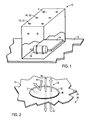
- FIG. 1 is a perspective view of a protective enclosure that includes one or more vents 18 with the improved filter membrane 32 in accordance with certain embodiments of the description.
- the filter membrane 32 may include plurality of layers with different pore sizes formed by a stretching technique with material, such as ePTFE.
- the enclosure 10 is coupled to a mounting plate 12 and protects equipment such as electronics from exposure to harmful contaminants such as oil, dirt, acid or other chemicals.
- the enclosure 10 may be used in an engine compartment of an automobile to house automotive components, such as automotive electronics 14 or a windshield wiper motor 16, for example.
- the enclosure 10 may also be used to protect a variety of electro-mechanical devices in commercial, industrial, and consumer applications.
- the enclosure 10 may protect devices in vehicles, such as automotive or aircraft.
- the enclosure 10 may contain motors, motor housings, microelectronics, circuit boards, memory, hard drives, processors, control units, sensors, GPS units, alarm units, vehicle black boxes, vehicle lamps (e.g., head lamp, tail tamp, etc.), or other electro-mechanical units.
- the enclosure 10 may include one or more vents 18, in accordance with embodiments.
- the vents 18 allow air and moisture to pass through the enclosure 10, while blocking oil, dust, or other contaminants from entering the enclosure 10.
- Line 2-2 shows the location of a close-up view of one of the vents 18 illustrated in FIG. 2 .
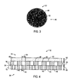
- FIG. 2 is a perspective view of an embodiment of one of the vents 18 of FIG. 1 .
- the vent 18 includes an opening 30 in the enclosure 10, over which a filter membrane 32 is placed.
- the filter membrane 32 may include several layers of different porosity.
- the filter membrane 32 may be held in position over the opening 30 with a layer of adhesive around the perimeter of the filter membrane 32. It can also be heat welded, laser welded or insert molded over the opening.
- the vent 18 allows the enclosure 10 to breathe (e.g., flow air in and out of the enclosure 10) while keeping contaminants out of the enclosure 10.
- the "dirty" side 34 of the vent 18 or filter membrane 32 is the side that is exposed to contaminants that may be present in the external environment outside of the enclosure 10, while the “clean” side 36 of the vent 18 or filter membrane 32 is the side that faces the internal space within the enclosure 10 where the protected components are housed.
- the temperature inside the enclosure 10 may rise or fall.
- the pressure inside the enclosure 10 may become slightly negative.
- air from the outside enters the enclosure 10 through the filter membrane 32 as indicated by arrow 38.
- the filter membrane 32 allows air to pass through the vent 18 while blocking contaminants such as dust, dirt, oil, fuel, acid, or other materials, as indicated by arrow 40.
- the pressure inside the enclosure 10 may become slightly positive.
- the filter membrane also allows moisture to escape as indicated by arrow 42. In this way, the filter membrane 32 allows the pressure inside the enclosure 10 to equalize and allows moisture to escape, while also blocking contaminants from entering the enclosure 10.
- Line 3-3 shows the location of a close-up view of the filter membrane 32 as shown in FIG. 3 .
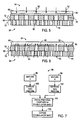
- FIG. 3 is a close-up top view of an embodiment of the filter membrane 32 of FIGS. 1 and 2 .
- the filter membrane 32 may include a mesh 46 of PTFE fibers 48 with voids or pores 50 between the fibers 48.
- the fiber mesh 46 shown in FIG. 3 may be fabricated by forming one or more layers of PTFE and stretching the layers of PTFE to separate the fibers 48 and open the pores 50, thus forming ePTFE. Accordingly, it will be appreciated that the size of the pores 50 may be determined, at least in part, by the degree to which the PTFE layer is stretched.
- the filter membrane 32 may include two or more ePTFE layers with different pore sizes.
- the PTFE mixtures used to form the ePTFE layers may different so that, as will be explained further below, the same degree of stretching will produce different pore sizes in the different layers.
- Other aspects of the filter membrane 32 may be better understood with reference to FIG. 4 .
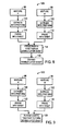
- FIG. 4 is a cross section of an embodiment of the filter membrane 32 of FIGS. 1-3 with two ePTFE layers 52 and 54.
- the filter membrane 32 may include a bottom layer 52 facing the clean side 36 of the filter membrane 32, a top layer 54 facing the dirty side 34 of the filter membrane 32, and a transition layer 56 that forms an interface between the bottom layer 52 and the top layer 54.
- a thickness 58 of the bottom layer 52 and a thickness 60 of the top layer 54 may both be at least less than approximately 13, 25, 51, 76, 102, 127, 152, 178, 203, 229, 254 or 635 ⁇ m (respectively 0.5,1, 2, 3, 4, 5, 6, 7, 8, 9, 10 or 25 mils).
- a mil is one thousandth of an inch (i.e., 0.001 inch).
- the thicknesses 58 and 60 may range between approximately 25 to 102 ⁇ m (1 to 4 mils, i.e., 0.001 to 0.004 inch). These thicknesses 58 and 60 may be the same or different from one another.
- the thickness 58 can be approximately 10, 20, 30, 40, 50, 60, 70, 80, or 90 percent of the thickness 60.
- the filter membrane 32 may include any number of layers, e.g., 2, 3, 4, 5, 6, 7, 8, 9, or 10.
- the top layer 54 may face the clean side 36 of the filter membrane 32, and the bottom layer 52 may face the dirty side 34 of the filter membrane 32.
- the pores 50 may range in diameter from approximately 0.01 to 10, 0.01 to 5, 0.01 to 3.0, or 0.01 to 1.0 microns. As appreciated, a micron is one millionth of a meter.
- an average diameter 62 of the pores 50 in the bottom layer 52 may be smaller than an average diameter 64 of the pores 50 in the top layer 54.
- the average diameter 62 of the pores 50 in the top layer 54 may be approximately 0.05 to 1.0 microns larger than the average diameter 64 of the pores 50 in the bottom layer 52.
- the average diameter 62 of the pores 50 in the bottom layer 52 may be approximately 0.15 to 0.25 microns, while the average diameter 64 of the pores 50 of the top layer 54 may be approximately 0.25 to 0.35 microns. In another embodiment, the average diameter 62 of the pores 50 in the bottom layer 52 may be less than approximately 0.2 microns, and the average diameter 64 of the pores 50 of the top layer 54 may be greater than approximately 0.8 microns.
- the average diameter 62 of the pores 50 in the bottom layer 52 may be at least less than approximately 10, 20, 30, 40, 50, 60, 70, or 80 percent of the average diameter 64 of the pores 50 of the top layer 54, wherein the pores 50 of both layers 52 and 54 may be less than approximately 1, 2, 3, 4, 5, 6, 7, 8, 9, or 10 microns.
- the average diameter 62 of the pores 50 in the bottom layer 52 may be at least less than approximately 50 percent of the average diameter 64 of the pores 50 of the top layer 54, wherein the pores 50 of both layers 52 and 54 may be less than approximately 10 microns.
- the filter membrane 32 may include more than two layers, each with progressively smaller pores.
- the bottom layer 52 and the top layer 54 are coupled together at the transition layer 56.
- the bottom layer 52 and the top layer 54 may be coupled to one another through heating and compression.
- the bottom layer 52 and the top layer 54 may be co-stretched, i.e., coupled together and then stretched at the same time to form the pores 50.
- the transition layer 56 may provide a region of resistance to the flow of contaminants, as will be described further below with reference to FIGS. 5 and 6 .
- the transition layer 56 represents a directional change and cross-sectional area change for the flow through the filter membrane 32.
- the filter membrane 32 may also include a substrate layer 66 that serves to provide improved durability of the filter membrane 32.
- the substrate layer 66 strengthens the filter membrane 32 without significantly altering the filtering properties provided by the bottom and top ePTFE layers 52 and 54.
- the substrate layer 66 may include any durable, flexible material that provides a high permittivity, such as polyester, for example.
- the substrate layer 66 may be a woven fabric or non-woven fabric.
- the thickness 68 of the substrate layer 66 may be approximately one to four millimeters.
- the filter membrane 32 may be chemically treated with one or more individual chemical treatments or a combined chemical treatment to increase the oil repellant and/or water repellant properties of the filter membrane 32 as well as the chemical resistivity of the filter membrane 32.
- the filter membrane 32 may be treated with a fluorocarbon-based surfactant, a fluoro-protectant, a fluorinated copolymer, or a combination thereof.
- the filter membrane 32 may be treated with one or more treatments from the Zonyl family of products by Dupont of Wilmington, Delaware.
- the dirty side 34 (e.g., the top layer 54) of the filter membrane 32 may be exposed to a number of contaminants.
- the dirty side 34 of the filter membrane 32 may be exposed to oil, gasoline, diesel fuel, exhaust, and so forth. Certain of these contaminants may have a tendency to build up inside the pores 50 of the filter membrane 32, thereby blocking the pores 50 and reducing the air flow through the filter membrane 32.
- the transition layer 56 provides a layer of increased resistance to the flow of contaminants and thus reduces clogging of the filter membrane 32.
- At least approximately 40, 50, 60, 70, or 80 percent of the original air flow through the filter membrane 32 will be maintained due to the anti-clogging properties of the filter membrane 32.
- the increased clogging resistance of the filter membrane 32 may be better understood with reference to FIGS. 5 and 6 .
- FIGS. 5 and 6 are cross-sectional views of the filter membrane 32 of FIGS. 1-4 , illustrating the anti-clogging effects of the filter membrane 32, in accordance with an embodiment.
- FIG. 5 illustrates the filter membrane 32 during a period of negative pressure (e.g., pressure on clean side 36 is less than dirty side 34) within the enclosure 10
- FIG. 6 illustrates the filter membrane 32 during a period of positive pressure (e.g., pressure on clean side 36 is greater than dirty side 34) within the enclosure 10.
- the dirty side 34 of the filter membrane 32 may tend to collect a contaminant 80, which may be oil based, such as lubricating oil, gasoline or diesel fuel, for example.
- the top layer 54 may tend to repel the contaminant 80, a limited amount of the contaminant 80 may become trapped within the pores 50 of the top layer 54 and build up over time. Additionally, if the pressure inside the enclosure 10 is negative, air pressure from outside of the enclosure 10, as indicated by the arrows 82, may tend to push the contaminant 80 deeper into the filter membrane 32. However, although the contaminant 80 may be absorbed into the pores 50 of the top layer 54, the transition layer 56 blocks the contaminant 80 from passing completely through the filter membrane 32 and contaminating the pores 50 of the bottom layer 52. Therefore, the bottom layer 52 of the filter membrane 32 remains relatively free of the contaminant 80.
- the filter membrane 32 is shown during a period of positive pressure within the enclosure 10.
- the air pressure inside the enclosure 10 is positive, the air flow from inside the enclosure 10, as indicated by the arrows 84, may tend to force the contaminant 80 out of the filter membrane 32. Therefore, the pores 50 of the filter membrane 32 may tend to be cleared of the contaminant 80 each time the enclosure 10 experiences a period of positive pressure.
- the fact that the pores 50 of the bottom layer 52 remain relatively clear enables the positive air pressure to be more effectively focused on the contaminant 80 blocking the pores 50 of the top layer 54.
- the filter membrane 32 may be subjected to pressures ranging between approximately 0 to 965 kPa (0 to 140 psi).
- FIGS. 7-9 are flow charts of embodiments of processes of fabricating the filter membrane 32 of FIGS. 1-6 .
- the fabrication methods provided herein describe methods wherein the layers 52 and 54 of the filter membrane 32 are co-stretched, e.g., coupled together before being stretched.
- the composite multilayer filter membrane 32 is then stretched to form the desired pore 50 sizes, as described above in reference to FIG. 4 . Coupling the layers 52 and 54 prior to stretching, and then stretching the layers 52 and 54 simultaneously results in a simpler, less expensive, and faster production process.
- techniques for producing a two layer membrane are described, it will be appreciated that the techniques described herein may be extended to provide a filter membrane 32 with 3, 4, 5, 6, 7 or more layers.
- process 94 begins with the preparation of two PTFE mixtures: mixture A at block 96 and mixture B at block 98.
- the pore diameters 62 and 64 may be controlled, in part, through the preparation of the PTFE mixtures.
- the difference between the pore diameters 62 and 64 in the bottom and top layers 52 and 54 may be achieved through the proper preparation of the PTFE mixtures A and B, such that equal stretching of both layers 52 and 54 will create different pore diameters 62 and 64 in the layers 52 and 54.
- compositions of mixture A and mixture B may be any suitable PTFE composition that results in differing pore diameters 62 and 64 in the bottom and top layers 52 and 54.
- the mixtures A and B may have different amounts of lube agents or lubricating agents, which are mixed with the PTFE.
- mixture A 96 and mixture B 98 may be extruded at blocks 100 and 102, respectively, forming two preforms of PTFE.
- both of the extruded preforms may be pressed and flattened to achieve a certain thickness.
- the pressing process forms a double-layer sheet of PTFE, the thickness of which may be controlled, in part, by the pressure applied to the two preforms.
- the above processes may produce significant amounts of heat in the PTFE sheet due to friction. Therefore, the equipment may also be configured to cool the double-layer sheet of PTFE during processing.
- the double-layer sheet of PTFE may be expanded, i.e. stretched, to form the pores 50.
- the expansion of the double-layer PTFE sheet may be controlled to determine the desired pore diameters 62 and 64 on the bottom 52 and top 54 layers.
- the relative difference between the pore diameters 62 and 64 on the bottom 52 and top 54 layers may be substantially or entirely based on steps 96 and 98, wherein the PTFE mixtures A and B were prepared.
- the double-layer PTFE sheet may be expanded longitudinally (i.e. relative to the length of sheet), laterally (i.e. relative to the width of the sheet), or both.
- the substrate layer 66 may be added to form the filter membrane 32.
- the expansion step 106 may provide an expansion of approximately 10 to 70 percent.
- the expansion step 106 may provide an expansion of at least greater than approximately 10, 20, 30, 40, 50, 60, 70, or greater percent.
- process 108 of FIG. 8 also begins with the preparation of two PTFE mixtures: mixture A at block 96 and mixture B at block 98, and extrusion of two PTFE preforms at blocks 100 and 102.
- each billet is pressed separately at blocks 110 and 112, respectively forming two PTFE sheets. After the pressing steps of blocks 110 and 112, the PTFE sheets may be wet.
- the two PTFE sheets may be pressed together while the PTFE sheets are still wet, forming a double layer PTFE sheet.
- the double-layer PTFE sheet is expanded, as described above in relation to FIG. 7 .
- the substrate layer 66 may be added to form the filter membrane 32.
- process 120 also begins with the preparation of two PTFE mixtures: mixture A at block 96 and mixture B at block 98, and extrusion of two PTFE preforms at blocks 100 and 102, respectively. Each preform may then be pressed separately at blocks 122 and 124, respectively forming two PTFE sheets. After pressing, the two PTFE sheets may then be dried. Next, the two dried PTFE sheets may be expanded together at block 126, forming a double-layer sheet of ePTFE.
- the substrate layer 66 may be added to form the filter membrane 32.
- the foregoing conditions of process 120 provide a permanent mechanical bond between the sheets.
Landscapes
- Chemical & Material Sciences (AREA)
- Chemical Kinetics & Catalysis (AREA)
- Engineering & Computer Science (AREA)
- Manufacturing & Machinery (AREA)
- Separation Using Semi-Permeable Membranes (AREA)
- Filtering Materials (AREA)
Description
- The subject matter disclosed herein relates generally to filtration membranes.
- Filtration membranes are used in a wide range of applications. In general, filtration membranes provide a barrier to contaminants while allowing other desired substances to pass through the membrane. For example, the filtration membranes may block flow of dust and other contaminants, while allowing air and moisture to pass through the membranes. Unfortunately, exposure to certain contamination environments can cause clogging of the filtration membranes, which may reduce the airflow performance of the membranes over time.
-
US 6,214,093 discloses a filter medium for air filters in which porous PTFE membrane layers are provided. -
US 5,462,586 discusses an oil and water repellent gas-permeable filter in which a porous filler material is coated with fluoropolymers. -
US 2009/0061205 discloses a crystalline polymer microporous film including two or more crystalline polymer layers. -
US 2002/0045041 relates to a microporous membrane with a stratified pore structure. - Various aspects and embodiments of the present invention are defined by the appended claims.
- Various features, aspects, and advantages of the present invention will become better understood when the following detailed description is read with reference to the accompanying drawings in which like characters represent like parts throughout the drawings, wherein:
-
FIG. 1 is a perspective view of a protective enclosure that includes one or more vents with an improved filter membrane in accordance with certain embodiments of the description; -
FIG. 2 is a perspective view of an embodiment of one of the vents ofFIG. 1 ; -
FIG. 3 is a top close-up view of an embodiment of the filter membrane ofFIGS 1 and 2 ; -
FIG. 4 is a cross-sectional view of an embodiment of a filter membrane with two polymer layers; -
FIGS. 5 and 6 are cross-sectional views of the filter membrane ofFIGS. 1-4 , illustrating the anti-clogging effects of the filter membrane; and -
FIGS. 7-8 are flow charts of embodiments of methods of fabricating the filter membrane ofFIGS. 1-6 , with the embodiments ofFIGS 7 and8 not part of the invention and the embodiment ofFIG 9 being in accordance with the invention. - One or more specific embodiments of the present description will be described below. In an effort to provide a concise description of these embodiments, all features of an actual implementation may not be described in the specification. It should be appreciated that in the development of any such actual implementation, as in any engineering or design project, numerous implementation-specific decisions must be made to achieve the developers' specific goals, such as compliance with system-related and business-related constraints, which may vary from one implementation to another. Moreover, it should be appreciated that such a development effort might be complex and time consuming, but would nevertheless be a routine undertaking of design, fabrication, and manufacture for those of ordinary skill having the benefit of this disclosure.
- When introducing elements of various embodiments of the present description, the articles "a," "an," "the," and "said" are intended to mean that there are one or more of the elements. The terms "comprising," "including," and "having" are intended to be inclusive and mean that there may be additional elements other than the listed elements.
- Various embodiments of the present description relate to a multi-layer filter membrane with improved anti-clogging characteristics that may be used in micro-venting applications. Micro-vents are low flow-volume vents that use a permeable membrane for providing a barrier to contaminants while allowing other desired substances to pass through the membrane. Micro-vents may be used in enclosures that house sensitive electro-mechanical equipment or units. The enclosure protects the electronics from dust and other contaminants, while the micro-vent allows air and moisture to pass through, thereby preventing a pressure or temperature buildup inside the enclosure. In some embodiments, a multi-layer filter membrane, in accordance with embodiments, may be fabricated by jointly stretching or expanding a plurality of layers of polytetrafluoroethylene (PTFE) to create a web-like mesh of microscopic pores in each PTFE layer. Each layer of the resulting multi-layer membrane may be referred to as expanded PTFE (ePTFE). ePTFE is particularly useful as a filtration membrane for a wide variety of applications because it is chemically inert and thermally stable. Furthermore, the multi-layer filter membrane may include at least two layers, each with different pore sizes. For example, the filter membrane may include 2, 3, 4, 5, 6, 7, 8, 9, 10, or more layers of the same or different polymeric porous layers with different pore sizes, arrangements, angles, and so forth. The pores may progressively change in average diameter from one layer to another, e.g., 10, 20, 30, 40, 50, 60, 70, 80, 90, or 100 percent change.
- In addition, a transition layer or interface may exist between adjacent layers to block the flow of contaminants from one layer to another. For example, transition layer may represent a misalignment of the pores between the adjacent layers, e.g., at least approximately 10, 20, 30, 40, 50, 60, or 70 percent misalignment. In other words, the misalignment may be described as a partial, but not complete, overlap of the pores between the adjacent layers. For example, less than approximately 30, 40, 50, or 60 percent of the cross-sectional area of a pore in one layer may overlap with a corresponding pore in the adjacent layer. Thus, the misalignment may cause a change in flow direction, restriction in flow, and the like, to block contaminants from completely passing through from the layer with large pores to the adjacent layer with small pores. The transition layer may be a direct thermal or chemical bond between the adjacent layers, a thin layer with pores, or any suitable configuration to block flow between the adjacent layers.
- The contaminants may include particulate, chemicals, oils, fuels, engine exhaust, or other undesirable solids, liquids, or gases. As discussed below, the filter membrane may have a dirty side and a clean side corresponding to the filter layer with large pores and the filter layer with small pores, respectively. In certain embodiments, the dirty side with large pores may be positioned external to an enclosure housing electronics, drives, motors, or other equipment, while the clean side with small pores may be positioned internal to the enclosure. Accordingly, any contaminants that begin to clog the dirty side of the membrane may be more easily expelled from the pores when air is diffused or passed from the clean side to the dirty side.
- As discussed in detail below, the filter member may be formed by stretching materials alone or in combination with one another. For example, a plurality of sheets may be co-stretched (e.g., simultaneously stretched after bonding) to simultaneously create the plurality of layers with different pore sizes. The starting sheets may be the same or different materials. However, after stretching the sheets, the resulting pore sizes and arrangements may be significantly different as discussed in detail below. For example, the starting sheets may be made with the same materials after different processing steps, e.g., application of pressure, heat, mixing, and so forth. By further example, the starting sheets may be made with different mixtures of materials, e.g., a base material with different additives, agents, and solvents. These additives, agents, and solvents may or may not remain in the final multi-layer membrane. In certain embodiments, the amount of additives, agents, and solvents in each mixture may at least partially control the final properties, e.g., porosity, of each layer in the multi-layer membrane. For example, the different mixtures may have PTFE as a base material, which is mixed with different amounts of lube agents or lubricating agent.
-
FIG. 1 is a perspective view of a protective enclosure that includes one ormore vents 18 with the improvedfilter membrane 32 in accordance with certain embodiments of the description. As discussed in detail below, thefilter membrane 32 may include plurality of layers with different pore sizes formed by a stretching technique with material, such as ePTFE. Theenclosure 10 is coupled to amounting plate 12 and protects equipment such as electronics from exposure to harmful contaminants such as oil, dirt, acid or other chemicals. In some embodiments, theenclosure 10 may be used in an engine compartment of an automobile to house automotive components, such asautomotive electronics 14 or awindshield wiper motor 16, for example. Theenclosure 10 may also be used to protect a variety of electro-mechanical devices in commercial, industrial, and consumer applications. For example, theenclosure 10 may protect devices in vehicles, such as automotive or aircraft. Theenclosure 10 may contain motors, motor housings, microelectronics, circuit boards, memory, hard drives, processors, control units, sensors, GPS units, alarm units, vehicle black boxes, vehicle lamps (e.g., head lamp, tail tamp, etc.), or other electro-mechanical units. To block moisture from collecting in theenclosure 10, theenclosure 10 may include one ormore vents 18, in accordance with embodiments. Thevents 18 allow air and moisture to pass through theenclosure 10, while blocking oil, dust, or other contaminants from entering theenclosure 10. Line 2-2 shows the location of a close-up view of one of thevents 18 illustrated inFIG. 2 . -
FIG. 2 is a perspective view of an embodiment of one of thevents 18 ofFIG. 1 . Thevent 18 includes anopening 30 in theenclosure 10, over which afilter membrane 32 is placed. As discussed below, thefilter membrane 32 may include several layers of different porosity. Thefilter membrane 32 may be held in position over theopening 30 with a layer of adhesive around the perimeter of thefilter membrane 32. It can also be heat welded, laser welded or insert molded over the opening. As discussed above, thevent 18 allows theenclosure 10 to breathe (e.g., flow air in and out of the enclosure 10) while keeping contaminants out of theenclosure 10. For purposes of the present disclosure, the "dirty"side 34 of thevent 18 orfilter membrane 32 is the side that is exposed to contaminants that may be present in the external environment outside of theenclosure 10, while the "clean"side 36 of thevent 18 orfilter membrane 32 is the side that faces the internal space within theenclosure 10 where the protected components are housed. - As environmental conditions around the
enclosure 10 vary, the temperature inside theenclosure 10 may rise or fall. When the temperature falls, the pressure inside theenclosure 10 may become slightly negative. To equalize the negative pressure, air from the outside enters theenclosure 10 through thefilter membrane 32 as indicated byarrow 38. Thefilter membrane 32 allows air to pass through thevent 18 while blocking contaminants such as dust, dirt, oil, fuel, acid, or other materials, as indicated byarrow 40. When the temperature rises, the pressure inside theenclosure 10 may become slightly positive. To equalize the positive pressure, air from inside theenclosure 10 exits through thefilter membrane 32 as indicated byarrow 42. In certain embodiments, the filter membrane also allows moisture to escape as indicated byarrow 42. In this way, thefilter membrane 32 allows the pressure inside theenclosure 10 to equalize and allows moisture to escape, while also blocking contaminants from entering theenclosure 10. Line 3-3 shows the location of a close-up view of thefilter membrane 32 as shown inFIG. 3 . -
FIG. 3 is a close-up top view of an embodiment of thefilter membrane 32 ofFIGS. 1 and 2 . As shown inFIG. 3 , thefilter membrane 32 may include amesh 46 ofPTFE fibers 48 with voids orpores 50 between thefibers 48. As will be discussed further below, thefiber mesh 46 shown inFIG. 3 may be fabricated by forming one or more layers of PTFE and stretching the layers of PTFE to separate thefibers 48 and open thepores 50, thus forming ePTFE. Accordingly, it will be appreciated that the size of thepores 50 may be determined, at least in part, by the degree to which the PTFE layer is stretched. Additionally, although not shown inFIG. 3 , thefilter membrane 32 may include two or more ePTFE layers with different pore sizes. For example, the PTFE mixtures used to form the ePTFE layers may different so that, as will be explained further below, the same degree of stretching will produce different pore sizes in the different layers. Other aspects of thefilter membrane 32 may be better understood with reference toFIG. 4 . -
FIG. 4 is a cross section of an embodiment of thefilter membrane 32 ofFIGS. 1-3 with twoePTFE layers 52 and 54. As shown inFIG. 4 , thefilter membrane 32 may include abottom layer 52 facing theclean side 36 of thefilter membrane 32, a top layer 54 facing thedirty side 34 of thefilter membrane 32, and atransition layer 56 that forms an interface between thebottom layer 52 and the top layer 54. Athickness 58 of thebottom layer 52 and athickness 60 of the top layer 54 may both be at least less than approximately 13, 25, 51, 76, 102, 127, 152, 178, 203, 229, 254 or 635 µm (respectively 0.5,1, 2, 3, 4, 5, 6, 7, 8, 9, 10 or 25 mils). As appreciated, a mil is one thousandth of an inch (i.e., 0.001 inch). In certain embodiments, thethicknesses thicknesses thickness 58 can be approximately 10, 20, 30, 40, 50, 60, 70, 80, or 90 percent of thethickness 60. Additionally, thefilter membrane 32 may include any number of layers, e.g., 2, 3, 4, 5, 6, 7, 8, 9, or 10. Furthermore, in alternate embodiments, the top layer 54 may face theclean side 36 of thefilter membrane 32, and thebottom layer 52 may face thedirty side 34 of thefilter membrane 32. - Also shown in
FIG. 4 are thepores 50, which, in some embodiments, may range in diameter from approximately 0.01 to 10, 0.01 to 5, 0.01 to 3.0, or 0.01 to 1.0 microns. As appreciated, a micron is one millionth of a meter. Moreover, anaverage diameter 62 of thepores 50 in thebottom layer 52 may be smaller than anaverage diameter 64 of thepores 50 in the top layer 54. For example, theaverage diameter 62 of thepores 50 in the top layer 54 may be approximately 0.05 to 1.0 microns larger than theaverage diameter 64 of thepores 50 in thebottom layer 52. In one embodiment, theaverage diameter 62 of thepores 50 in thebottom layer 52 may be approximately 0.15 to 0.25 microns, while theaverage diameter 64 of thepores 50 of the top layer 54 may be approximately 0.25 to 0.35 microns. In another embodiment, theaverage diameter 62 of thepores 50 in thebottom layer 52 may be less than approximately 0.2 microns, and theaverage diameter 64 of thepores 50 of the top layer 54 may be greater than approximately 0.8 microns. In some embodiments, theaverage diameter 62 of thepores 50 in thebottom layer 52 may be at least less than approximately 10, 20, 30, 40, 50, 60, 70, or 80 percent of theaverage diameter 64 of thepores 50 of the top layer 54, wherein thepores 50 of bothlayers 52 and 54 may be less than approximately 1, 2, 3, 4, 5, 6, 7, 8, 9, or 10 microns. For example, theaverage diameter 62 of thepores 50 in thebottom layer 52 may be at least less than approximately 50 percent of theaverage diameter 64 of thepores 50 of the top layer 54, wherein thepores 50 of bothlayers 52 and 54 may be less than approximately 10 microns. In some embodiments, thefilter membrane 32 may include more than two layers, each with progressively smaller pores. - The
bottom layer 52 and the top layer 54 are coupled together at thetransition layer 56. As will be described further below, thebottom layer 52 and the top layer 54 may be coupled to one another through heating and compression. Moreover, thebottom layer 52 and the top layer 54 may be co-stretched, i.e., coupled together and then stretched at the same time to form thepores 50. As a result of thedifferent pore 50 sizes in thebottom layer 52 and the top layer 54, thepores 50 in thebottom layer 52 and thepores 50 in the top layer 54 will generally not be aligned with one another at thetransition layer 56. Thus, thetransition layer 56 may provide a region of resistance to the flow of contaminants, as will be described further below with reference toFIGS. 5 and 6 . For example, thetransition layer 56 represents a directional change and cross-sectional area change for the flow through thefilter membrane 32. - The
filter membrane 32 may also include asubstrate layer 66 that serves to provide improved durability of thefilter membrane 32. Thesubstrate layer 66 strengthens thefilter membrane 32 without significantly altering the filtering properties provided by the bottom and top ePTFE layers 52 and 54. Thesubstrate layer 66 may include any durable, flexible material that provides a high permittivity, such as polyester, for example. For example, thesubstrate layer 66 may be a woven fabric or non-woven fabric. In some embodiments, thethickness 68 of thesubstrate layer 66 may be approximately one to four millimeters. - Furthermore, in some embodiments, the
filter membrane 32 may be chemically treated with one or more individual chemical treatments or a combined chemical treatment to increase the oil repellant and/or water repellant properties of thefilter membrane 32 as well as the chemical resistivity of thefilter membrane 32. For example, thefilter membrane 32 may be treated with a fluorocarbon-based surfactant, a fluoro-protectant, a fluorinated copolymer, or a combination thereof. In certain embodiments, thefilter membrane 32 may be treated with one or more treatments from the Zonyl family of products by Dupont of Wilmington, Delaware. - When the
filter membrane 32 is placed into service, the dirty side 34 (e.g., the top layer 54) of thefilter membrane 32 may be exposed to a number of contaminants. In automotive applications, for example, thedirty side 34 of thefilter membrane 32 may be exposed to oil, gasoline, diesel fuel, exhaust, and so forth. Certain of these contaminants may have a tendency to build up inside thepores 50 of thefilter membrane 32, thereby blocking thepores 50 and reducing the air flow through thefilter membrane 32. However, as mentioned above, thetransition layer 56 provides a layer of increased resistance to the flow of contaminants and thus reduces clogging of thefilter membrane 32. In some embodiments, at least approximately 40, 50, 60, 70, or 80 percent of the original air flow through thefilter membrane 32 will be maintained due to the anti-clogging properties of thefilter membrane 32. The increased clogging resistance of thefilter membrane 32 may be better understood with reference toFIGS. 5 and 6 . -
FIGS. 5 and 6 are cross-sectional views of thefilter membrane 32 ofFIGS. 1-4 , illustrating the anti-clogging effects of thefilter membrane 32, in accordance with an embodiment. Specifically,FIG. 5 illustrates thefilter membrane 32 during a period of negative pressure (e.g., pressure onclean side 36 is less than dirty side 34) within theenclosure 10, andFIG. 6 illustrates thefilter membrane 32 during a period of positive pressure (e.g., pressure onclean side 36 is greater than dirty side 34) within theenclosure 10. As shown inFIG. 5 , thedirty side 34 of thefilter membrane 32 may tend to collect acontaminant 80, which may be oil based, such as lubricating oil, gasoline or diesel fuel, for example. Although, the top layer 54 may tend to repel thecontaminant 80, a limited amount of thecontaminant 80 may become trapped within thepores 50 of the top layer 54 and build up over time. Additionally, if the pressure inside theenclosure 10 is negative, air pressure from outside of theenclosure 10, as indicated by thearrows 82, may tend to push thecontaminant 80 deeper into thefilter membrane 32. However, although thecontaminant 80 may be absorbed into thepores 50 of the top layer 54, thetransition layer 56 blocks thecontaminant 80 from passing completely through thefilter membrane 32 and contaminating thepores 50 of thebottom layer 52. Therefore, thebottom layer 52 of thefilter membrane 32 remains relatively free of thecontaminant 80. - Turning to
FIG. 6 , thefilter membrane 32 is shown during a period of positive pressure within theenclosure 10. When the air pressure inside theenclosure 10 is positive, the air flow from inside theenclosure 10, as indicated by thearrows 84, may tend to force thecontaminant 80 out of thefilter membrane 32. Therefore, thepores 50 of thefilter membrane 32 may tend to be cleared of thecontaminant 80 each time theenclosure 10 experiences a period of positive pressure. The fact that thepores 50 of thebottom layer 52 remain relatively clear enables the positive air pressure to be more effectively focused on thecontaminant 80 blocking thepores 50 of the top layer 54. In this way, thepositive air flow 84 clears thecontaminant 80 from thepores 50 of the top layer 54, and the top layer 54 will, therefore, be better able to pass air into theenclosure 10 during the next period of negative pressure. In certain embodiments, thefilter membrane 32 may be subjected to pressures ranging between approximately 0 to 965 kPa (0 to 140 psi). -
FIGS. 7-9 are flow charts of embodiments of processes of fabricating thefilter membrane 32 ofFIGS. 1-6 . The fabrication methods provided herein describe methods wherein thelayers 52 and 54 of thefilter membrane 32 are co-stretched, e.g., coupled together before being stretched. The compositemultilayer filter membrane 32 is then stretched to form the desiredpore 50 sizes, as described above in reference toFIG. 4 . Coupling thelayers 52 and 54 prior to stretching, and then stretching thelayers 52 and 54 simultaneously results in a simpler, less expensive, and faster production process. Furthermore, although techniques for producing a two layer membrane are described, it will be appreciated that the techniques described herein may be extended to provide afilter membrane 32 with 3, 4, 5, 6, 7 or more layers. - Turning first to
FIG. 7 , afirst process 94 of fabricating afilter membrane 32 not part of the invention is shown. As shown inFIG. 7 ,process 94 begins with the preparation of two PTFE mixtures: mixture A atblock 96 and mixture B atblock 98. The pore diameters 62 and 64 may be controlled, in part, through the preparation of the PTFE mixtures. Moreover, due to the fact that the layers are stretched together to form thepores 50, the difference between thepore diameters top layers 52 and 54 may be achieved through the proper preparation of the PTFE mixtures A and B, such that equal stretching of bothlayers 52 and 54 will createdifferent pore diameters layers 52 and 54. Accordingly, the compositions of mixture A and mixture B may be any suitable PTFE composition that results in differingpore diameters top layers 52 and 54. For example, the mixtures A and B may have different amounts of lube agents or lubricating agents, which are mixed with the PTFE. - After preparing the PTFE mixtures,
mixture A 96 andmixture B 98 may be extruded atblocks block 104, both of the extruded preforms may be pressed and flattened to achieve a certain thickness. The pressing process forms a double-layer sheet of PTFE, the thickness of which may be controlled, in part, by the pressure applied to the two preforms. The above processes may produce significant amounts of heat in the PTFE sheet due to friction. Therefore, the equipment may also be configured to cool the double-layer sheet of PTFE during processing. - Next, at
block 106, the double-layer sheet of PTFE may be expanded, i.e. stretched, to form thepores 50. The expansion of the double-layer PTFE sheet may be controlled to determine the desiredpore diameters pore diameters steps block 106, thesubstrate layer 66 may be added to form thefilter membrane 32. In certain embodiments, theexpansion step 106 may provide an expansion of approximately 10 to 70 percent. For example, theexpansion step 106 may provide an expansion of at least greater than approximately 10, 20, 30, 40, 50, 60, 70, or greater percent. - Turning now to
FIG. 8 , asecond process 108 of fabricating afilter membrane 32 not part of the invention is shown. As inprocess 94 ofFIG. 7 ,process 108 ofFIG. 8 also begins with the preparation of two PTFE mixtures: mixture A atblock 96 and mixture B atblock 98, and extrusion of two PTFE preforms atblocks FIG. 7 , inprocess 108, each billet is pressed separately atblocks blocks block 114, the two PTFE sheets may be pressed together while the PTFE sheets are still wet, forming a double layer PTFE sheet. Next, atblock 118, the double-layer PTFE sheet is expanded, as described above in relation toFIG. 7 . After the double-layer sheet of PTFE is expanded atblock 118, thesubstrate layer 66 may be added to form thefilter membrane 32. - Turning now to
FIG. 9 , athird process 120 of fabricating afilter membrane 32 according to the invention is shown. As inprocess 94 ofFIG. 7 andprocess 108 ofFIG. 8 ,process 120 also begins with the preparation of two PTFE mixtures: mixture A atblock 96 and mixture B atblock 98, and extrusion of two PTFE preforms atblocks blocks block 126, forming a double-layer sheet of ePTFE. In this embodiment, sufficient pressure is applied during the expanding process to adhere the two PTFE sheets to one another. After the double-layer sheet of PTFE is expanded atblock 126, thesubstrate layer 66 may be added to form thefilter membrane 32. The foregoing conditions ofprocess 120 provide a permanent mechanical bond between the sheets.
Claims (3)
- A method for forming a filter membrane (32), comprising:bonding two or more PTFE layers (52, 54) andco-stretching the two or more PTFE layers (52, 54), after bonding, to form the filter membrane (32) having porosities and pore sizes that change from one layer to another,the method comprising the following steps:a first PTFE mixture is prepared (96) configured to provide a first pore size;a second PTFE mixture is prepared (98) configured to provide a second pore size, wherein the first and second PTFE mixtures have different amounts of lubricating agents such that the first and second pore sizes after co-stretching are different;the first PTFE mixture is extruded (100) into a first preform and the second PTFE mixture is extruded (102) into a second preform;the first preform and the second preform are combined into a double-layered PTFE sheet, wherein combining the first preform and the second preform comprises:pressing (122) the first preform into a first sheet, pressing (124) the second preform into a second sheet, wherein each preform is pressed separately,drying the first and second sheets, andpressurizing the first dried sheet and the second dried sheet together during co-stretching (126); andthe double-layered PTFE sheet is further co-stretched to form the filter membrane (32) comprising a first layer (52) that includes pores (50) of the first pore size and a second layer (54) that includes pores (50) of the second pore size.
- The method of claim 1, wherein co-stretching comprises stretching the double-layered PTFE sheet, after bonding, by at least 20 percent.
- The method of claim 1 or 2, wherein co-stretching comprises stretching a bond interface (56) between each pair of adjacent layers (52, 54) of the double-layered PTFE sheet, and the bond interface (56) at least partially blocks flow through pores in the adjacent layers (52, 54).
Applications Claiming Priority (1)
| Application Number | Priority Date | Filing Date | Title |
|---|---|---|---|
| US12/409,137 US8118910B2 (en) | 2009-03-23 | 2009-03-23 | Layered filtration membrane and methods of making same |
Publications (2)
| Publication Number | Publication Date |
|---|---|
| EP2233200A1 EP2233200A1 (en) | 2010-09-29 |
| EP2233200B1 true EP2233200B1 (en) | 2015-11-04 |
Family
ID=42046378
Family Applications (1)
| Application Number | Title | Priority Date | Filing Date |
|---|---|---|---|
| EP10155744.5A Active EP2233200B1 (en) | 2009-03-23 | 2010-03-08 | Method of making a layered filtration membrane |
Country Status (4)
| Country | Link |
|---|---|
| US (1) | US8118910B2 (en) |
| EP (1) | EP2233200B1 (en) |
| JP (1) | JP5627257B2 (en) |
| CN (1) | CN101850201B (en) |
Families Citing this family (20)
| Publication number | Priority date | Publication date | Assignee | Title |
|---|---|---|---|---|
| JP5133039B2 (en) * | 2007-12-07 | 2013-01-30 | 日東電工株式会社 | Polytetrafluoroethylene porous membrane, method for producing the same, and waterproof air-permeable filter |
| EP2397217A4 (en) * | 2009-02-16 | 2013-07-31 | Sumitomo Elec Fine Polymer Inc | Porous multilayer filter and method for producing same |
| US9132616B2 (en) * | 2010-08-31 | 2015-09-15 | Bha Altair, Llc | Multi-layer composite membrane materials and methods therefor |
| TWI453114B (en) * | 2012-05-11 | 2014-09-21 | Entire Technology Co Ltd | Manufacturing method for porous composite film |
| CN102927953B (en) * | 2012-11-08 | 2015-06-10 | 西南石油大学 | Test method for hydraulics size of shear flow polymer and test device thereof |
| US11090590B2 (en) | 2012-11-13 | 2021-08-17 | Hollingsworth & Vose Company | Pre-coalescing multi-layered filter media |
| US9149748B2 (en) | 2012-11-13 | 2015-10-06 | Hollingsworth & Vose Company | Multi-layered filter media |
| US9149749B2 (en) | 2012-11-13 | 2015-10-06 | Hollingsworth & Vose Company | Pre-coalescing multi-layered filter media |
| EP2958652A4 (en) * | 2013-02-25 | 2017-02-22 | Hollingsworth & Vose Company | Multi-layered filter media |
| CN103657276B (en) * | 2013-12-23 | 2016-02-10 | 北京大学 | A kind of Fine particulate matter filter structure and preparation method thereof |
| US10195542B2 (en) | 2014-05-15 | 2019-02-05 | Hollingsworth & Vose Company | Surface modified filter media |
| US10399024B2 (en) | 2014-05-15 | 2019-09-03 | Hollingsworth & Vose Company | Surface modified filter media |
| US10828587B2 (en) | 2015-04-17 | 2020-11-10 | Hollingsworth & Vose Company | Stable filter media including nanofibers |
| GB2547910A (en) * | 2016-03-02 | 2017-09-06 | Icon Tech Systems Ltd | Filter |
| CN108883377B (en) * | 2016-03-31 | 2021-05-07 | 日本碍子株式会社 | Porous support, method for producing porous support, separation membrane structure, and method for producing separation membrane structure |
| US10625196B2 (en) | 2016-05-31 | 2020-04-21 | Hollingsworth & Vose Company | Coalescing filter media |
| WO2018009197A1 (en) * | 2016-07-07 | 2018-01-11 | Hewlett-Packard Development Company, L.P. | Metal fluoropolymer composites |
| JP6875506B2 (en) | 2016-09-14 | 2021-05-26 | ダブリュ.エル.ゴア アンド アソシエーツ,ゲゼルシャフト ミット ベシュレンクテル ハフツングW.L. Gore & Associates, Gesellschaft Mit Beschrankter Haftung | Assembly to protect acoustic devices |
| JP6920042B2 (en) * | 2016-09-30 | 2021-08-18 | 日東電工株式会社 | Air filter filter media, air filter pack and air filter unit |
| CN106678980A (en) * | 2017-02-10 | 2017-05-17 | 上海帆煜自动化科技有限公司 | Wall-mounted air treatment device |
Family Cites Families (24)
| Publication number | Priority date | Publication date | Assignee | Title |
|---|---|---|---|---|
| NL296324A (en) * | 1962-08-06 | |||
| CA962021A (en) * | 1970-05-21 | 1975-02-04 | Robert W. Gore | Porous products and process therefor |
| US4969998A (en) * | 1984-04-23 | 1990-11-13 | W. L. Gore & Associates, Inc. | Composite semipermeable membrane |
| JPH078927B2 (en) * | 1989-12-07 | 1995-02-01 | ダイキン工業株式会社 | Method for producing polytetrafluoroethylene multilayer porous membrane |
| US5116650A (en) * | 1990-12-03 | 1992-05-26 | W. L. Gore & Associates, Inc. | Dioxole/tfe copolymer composites |
| JP2854223B2 (en) * | 1993-09-08 | 1999-02-03 | ジャパンゴアテックス株式会社 | Oil repellent waterproof ventilation filter |
| US6235377B1 (en) * | 1995-09-05 | 2001-05-22 | Bio Med Sciences, Inc. | Microporous membrane with a stratified pore structure created in situ and process |
| AU723265B2 (en) * | 1996-01-22 | 2000-08-24 | Usf Filtration And Separations Group Inc. | Highly porous polyvinylidene difluoride membranes |
| JP3273735B2 (en) * | 1996-05-17 | 2002-04-15 | 日東電工株式会社 | Polytetrafluoroethylene porous membrane and method for producing the same, sheet-like polytetrafluoroethylene molded article, and filter medium for air filter |
| US5938818A (en) * | 1997-08-22 | 1999-08-17 | Energy & Environmental Research Center Foundation | Advanced hybrid particulate collector and method of operation |
| JP2007111697A (en) * | 1998-07-08 | 2007-05-10 | Nitto Denko Corp | Air filter media |
| JP2000079332A (en) * | 1998-07-08 | 2000-03-21 | Nitto Denko Corp | Filter media for air filter |
| US6228477B1 (en) * | 1999-02-12 | 2001-05-08 | Bha Technologies, Inc. | Porous membrane structure and method |
| KR100409017B1 (en) * | 2000-06-23 | 2003-12-06 | 주식회사 엘지화학 | Multi-component composite membrane and method for preparing the same |
| JP2002301321A (en) * | 2001-04-05 | 2002-10-15 | Daikin Ind Ltd | Filter medium, filter pack and air filter unit using the same, and method of manufacturing filter medium |
| JP2003336874A (en) * | 2002-05-15 | 2003-11-28 | Nitto Denko Corp | Ventilation member and ventilation housing using the same |
| US7771818B2 (en) * | 2002-09-20 | 2010-08-10 | Bha Group, Inc. | Treatment of porous article |
| US7306729B2 (en) * | 2005-07-18 | 2007-12-11 | Gore Enterprise Holdings, Inc. | Porous PTFE materials and articles produced therefrom |
| CN101242889A (en) * | 2005-07-18 | 2008-08-13 | 戈尔企业控股股份有限公司 | Porous PTFE material and products produced therefrom |
| JP4916195B2 (en) * | 2006-03-09 | 2012-04-11 | 三菱樹脂株式会社 | Laminated porous film |
| JP2008055407A (en) * | 2006-08-01 | 2008-03-13 | Nitto Denko Corp | Method for producing polytetrafluoroethylene porous membrane and air filter medium |
| JP5220369B2 (en) * | 2007-09-04 | 2013-06-26 | 富士フイルム株式会社 | Crystalline polymer microporous membrane, method for producing the same, and filter for filtration |
| CN101861195A (en) * | 2007-11-14 | 2010-10-13 | 日东电工株式会社 | Filter medium, method for producing same, and filter unit |
| US8777051B2 (en) * | 2008-04-02 | 2014-07-15 | Brunswick Corporation | Fuel venting systems having protective membranes |
-
2009
- 2009-03-23 US US12/409,137 patent/US8118910B2/en active Active
-
2010
- 2010-03-08 EP EP10155744.5A patent/EP2233200B1/en active Active
- 2010-03-18 JP JP2010061737A patent/JP5627257B2/en not_active Expired - Fee Related
- 2010-03-23 CN CN201010155650.5A patent/CN101850201B/en active Active
Also Published As
| Publication number | Publication date |
|---|---|
| US20100236410A1 (en) | 2010-09-23 |
| US8118910B2 (en) | 2012-02-21 |
| CN101850201B (en) | 2015-09-02 |
| JP5627257B2 (en) | 2014-11-19 |
| CN101850201A (en) | 2010-10-06 |
| EP2233200A1 (en) | 2010-09-29 |
| JP2010221214A (en) | 2010-10-07 |
Similar Documents
| Publication | Publication Date | Title |
|---|---|---|
| US8118910B2 (en) | Layered filtration membrane and methods of making same | |
| CA2274078C (en) | Filter medium and air filter unit using the same | |
| KR101197358B1 (en) | Porous composite article | |
| JP5684634B2 (en) | Ventilation member | |
| KR101196282B1 (en) | Turbine air-intake filter | |
| TWI526243B (en) | Porous multi - layer filter | |
| CN1122555C (en) | Protective cover for fan-type cooling unit | |
| TWI428379B (en) | Porous polytetrafluoroethylene membrane and method of producing the same, and filter medium | |
| EP1750493B1 (en) | Fan cooling unit for cooling electronic components | |
| US20060207234A1 (en) | Coalescing filter elements comprising self-sustaining, bonded fiber structures | |
| KR20190096395A (en) | Polytetrafluoroethylene porous membrane, waterproof breathable membrane and waterproof breathable member using the same | |
| EP2481462A1 (en) | Water-proof and dust-proof membrane assembly and applications thereof | |
| KR20100103557A (en) | Porous polytetrafluoroethylene film, method for production thereof, and water-proof breathable filter | |
| CN101544073A (en) | Oleophobic laminated article | |
| JP2008055407A (en) | Method for producing polytetrafluoroethylene porous membrane and air filter medium | |
| JPH11137931A (en) | Air filter and manufacturing method thereof | |
| CN105848766A (en) | Moisture permeability filter material | |
| KR101308358B1 (en) | Asymmetric porous sheet, manufacturing method thereof and air purificaion filter using the same | |
| JPH1180397A (en) | Polytetrafluoroethylene porous membrane and method for producing the same | |
| WO2013031085A1 (en) | Joining member having ventilation function and joining structure using same | |
| JP7257966B2 (en) | Internal pressure adjustment members and electrical components for transportation equipment | |
| JP4879475B2 (en) | Ventilation filter member and ventilation casing using the same | |
| KR102406235B1 (en) | Tailored Multilayered Dust Capturing Media And Fabrication Method Thereof | |
| CN121534459A (en) | An air filter element, its preparation method and application |
Legal Events
| Date | Code | Title | Description |
|---|---|---|---|
| PUAI | Public reference made under article 153(3) epc to a published international application that has entered the european phase |
Free format text: ORIGINAL CODE: 0009012 |
|
| AK | Designated contracting states |
Kind code of ref document: A1 Designated state(s): AT BE BG CH CY CZ DE DK EE ES FI FR GB GR HR HU IE IS IT LI LT LU LV MC MK MT NL NO PL PT RO SE SI SK SM TR |
|
| 17P | Request for examination filed |
Effective date: 20110329 |
|
| 17Q | First examination report despatched |
Effective date: 20130813 |
|
| RAP1 | Party data changed (applicant data changed or rights of an application transferred) |
Owner name: BHA ALTAIR, LLC |
|
| REG | Reference to a national code |
Ref country code: DE Ref legal event code: R079 Ref document number: 602010028703 Country of ref document: DE Free format text: PREVIOUS MAIN CLASS: B01D0069120000 Ipc: B01D0046540000 |
|
| GRAP | Despatch of communication of intention to grant a patent |
Free format text: ORIGINAL CODE: EPIDOSNIGR1 |
|
| RIC1 | Information provided on ipc code assigned before grant |
Ipc: B01D 46/54 20060101AFI20150518BHEP Ipc: B01D 69/12 20060101ALI20150518BHEP Ipc: B01D 67/00 20060101ALI20150518BHEP Ipc: B01D 71/36 20060101ALI20150518BHEP |
|
| INTG | Intention to grant announced |
Effective date: 20150619 |
|
| GRAS | Grant fee paid |
Free format text: ORIGINAL CODE: EPIDOSNIGR3 |
|
| GRAA | (expected) grant |
Free format text: ORIGINAL CODE: 0009210 |
|
| AK | Designated contracting states |
Kind code of ref document: B1 Designated state(s): AT BE BG CH CY CZ DE DK EE ES FI FR GB GR HR HU IE IS IT LI LT LU LV MC MK MT NL NO PL PT RO SE SI SK SM TR |
|
| REG | Reference to a national code |
Ref country code: GB Ref legal event code: FG4D |
|
| REG | Reference to a national code |
Ref country code: CH Ref legal event code: EP |
|
| REG | Reference to a national code |
Ref country code: AT Ref legal event code: REF Ref document number: 758805 Country of ref document: AT Kind code of ref document: T Effective date: 20151115 |
|
| REG | Reference to a national code |
Ref country code: IE Ref legal event code: FG4D |
|
| REG | Reference to a national code |
Ref country code: DE Ref legal event code: R096 Ref document number: 602010028703 Country of ref document: DE |
|
| REG | Reference to a national code |
Ref country code: NL Ref legal event code: MP Effective date: 20151104 |
|
| REG | Reference to a national code |
Ref country code: LT Ref legal event code: MG4D |
|
| REG | Reference to a national code |
Ref country code: AT Ref legal event code: MK05 Ref document number: 758805 Country of ref document: AT Kind code of ref document: T Effective date: 20151104 |
|
| PG25 | Lapsed in a contracting state [announced via postgrant information from national office to epo] |
Ref country code: ES Free format text: LAPSE BECAUSE OF FAILURE TO SUBMIT A TRANSLATION OF THE DESCRIPTION OR TO PAY THE FEE WITHIN THE PRESCRIBED TIME-LIMIT Effective date: 20151104 Ref country code: LT Free format text: LAPSE BECAUSE OF FAILURE TO SUBMIT A TRANSLATION OF THE DESCRIPTION OR TO PAY THE FEE WITHIN THE PRESCRIBED TIME-LIMIT Effective date: 20151104 Ref country code: NO Free format text: LAPSE BECAUSE OF FAILURE TO SUBMIT A TRANSLATION OF THE DESCRIPTION OR TO PAY THE FEE WITHIN THE PRESCRIBED TIME-LIMIT Effective date: 20160204 Ref country code: IT Free format text: LAPSE BECAUSE OF FAILURE TO SUBMIT A TRANSLATION OF THE DESCRIPTION OR TO PAY THE FEE WITHIN THE PRESCRIBED TIME-LIMIT Effective date: 20151104 Ref country code: NL Free format text: LAPSE BECAUSE OF FAILURE TO SUBMIT A TRANSLATION OF THE DESCRIPTION OR TO PAY THE FEE WITHIN THE PRESCRIBED TIME-LIMIT Effective date: 20151104 Ref country code: HR Free format text: LAPSE BECAUSE OF FAILURE TO SUBMIT A TRANSLATION OF THE DESCRIPTION OR TO PAY THE FEE WITHIN THE PRESCRIBED TIME-LIMIT Effective date: 20151104 Ref country code: IS Free format text: LAPSE BECAUSE OF FAILURE TO SUBMIT A TRANSLATION OF THE DESCRIPTION OR TO PAY THE FEE WITHIN THE PRESCRIBED TIME-LIMIT Effective date: 20160304 |
|
| PG25 | Lapsed in a contracting state [announced via postgrant information from national office to epo] |
Ref country code: FI Free format text: LAPSE BECAUSE OF FAILURE TO SUBMIT A TRANSLATION OF THE DESCRIPTION OR TO PAY THE FEE WITHIN THE PRESCRIBED TIME-LIMIT Effective date: 20151104 Ref country code: GR Free format text: LAPSE BECAUSE OF FAILURE TO SUBMIT A TRANSLATION OF THE DESCRIPTION OR TO PAY THE FEE WITHIN THE PRESCRIBED TIME-LIMIT Effective date: 20160205 Ref country code: LV Free format text: LAPSE BECAUSE OF FAILURE TO SUBMIT A TRANSLATION OF THE DESCRIPTION OR TO PAY THE FEE WITHIN THE PRESCRIBED TIME-LIMIT Effective date: 20151104 Ref country code: PT Free format text: LAPSE BECAUSE OF FAILURE TO SUBMIT A TRANSLATION OF THE DESCRIPTION OR TO PAY THE FEE WITHIN THE PRESCRIBED TIME-LIMIT Effective date: 20160304 Ref country code: PL Free format text: LAPSE BECAUSE OF FAILURE TO SUBMIT A TRANSLATION OF THE DESCRIPTION OR TO PAY THE FEE WITHIN THE PRESCRIBED TIME-LIMIT Effective date: 20151104 Ref country code: AT Free format text: LAPSE BECAUSE OF FAILURE TO SUBMIT A TRANSLATION OF THE DESCRIPTION OR TO PAY THE FEE WITHIN THE PRESCRIBED TIME-LIMIT Effective date: 20151104 Ref country code: SE Free format text: LAPSE BECAUSE OF FAILURE TO SUBMIT A TRANSLATION OF THE DESCRIPTION OR TO PAY THE FEE WITHIN THE PRESCRIBED TIME-LIMIT Effective date: 20151104 |
|
| PG25 | Lapsed in a contracting state [announced via postgrant information from national office to epo] |
Ref country code: CZ Free format text: LAPSE BECAUSE OF FAILURE TO SUBMIT A TRANSLATION OF THE DESCRIPTION OR TO PAY THE FEE WITHIN THE PRESCRIBED TIME-LIMIT Effective date: 20151104 |
|
| REG | Reference to a national code |
Ref country code: DE Ref legal event code: R097 Ref document number: 602010028703 Country of ref document: DE |
|
| PG25 | Lapsed in a contracting state [announced via postgrant information from national office to epo] |
Ref country code: DK Free format text: LAPSE BECAUSE OF FAILURE TO SUBMIT A TRANSLATION OF THE DESCRIPTION OR TO PAY THE FEE WITHIN THE PRESCRIBED TIME-LIMIT Effective date: 20151104 Ref country code: EE Free format text: LAPSE BECAUSE OF FAILURE TO SUBMIT A TRANSLATION OF THE DESCRIPTION OR TO PAY THE FEE WITHIN THE PRESCRIBED TIME-LIMIT Effective date: 20151104 Ref country code: BE Free format text: LAPSE BECAUSE OF NON-PAYMENT OF DUE FEES Effective date: 20160331 Ref country code: RO Free format text: LAPSE BECAUSE OF FAILURE TO SUBMIT A TRANSLATION OF THE DESCRIPTION OR TO PAY THE FEE WITHIN THE PRESCRIBED TIME-LIMIT Effective date: 20151104 Ref country code: SK Free format text: LAPSE BECAUSE OF FAILURE TO SUBMIT A TRANSLATION OF THE DESCRIPTION OR TO PAY THE FEE WITHIN THE PRESCRIBED TIME-LIMIT Effective date: 20151104 Ref country code: SM Free format text: LAPSE BECAUSE OF FAILURE TO SUBMIT A TRANSLATION OF THE DESCRIPTION OR TO PAY THE FEE WITHIN THE PRESCRIBED TIME-LIMIT Effective date: 20151104 |
|
| PLBE | No opposition filed within time limit |
Free format text: ORIGINAL CODE: 0009261 |
|
| STAA | Information on the status of an ep patent application or granted ep patent |
Free format text: STATUS: NO OPPOSITION FILED WITHIN TIME LIMIT |
|
| 26N | No opposition filed |
Effective date: 20160805 |
|
| PG25 | Lapsed in a contracting state [announced via postgrant information from national office to epo] |
Ref country code: LU Free format text: LAPSE BECAUSE OF FAILURE TO SUBMIT A TRANSLATION OF THE DESCRIPTION OR TO PAY THE FEE WITHIN THE PRESCRIBED TIME-LIMIT Effective date: 20160308 Ref country code: MC Free format text: LAPSE BECAUSE OF FAILURE TO SUBMIT A TRANSLATION OF THE DESCRIPTION OR TO PAY THE FEE WITHIN THE PRESCRIBED TIME-LIMIT Effective date: 20151104 |
|
| REG | Reference to a national code |
Ref country code: CH Ref legal event code: PL |
|
| PG25 | Lapsed in a contracting state [announced via postgrant information from national office to epo] |
Ref country code: SI Free format text: LAPSE BECAUSE OF FAILURE TO SUBMIT A TRANSLATION OF THE DESCRIPTION OR TO PAY THE FEE WITHIN THE PRESCRIBED TIME-LIMIT Effective date: 20151104 |
|
| REG | Reference to a national code |
Ref country code: IE Ref legal event code: MM4A |
|
| PG25 | Lapsed in a contracting state [announced via postgrant information from national office to epo] |
Ref country code: BE Free format text: LAPSE BECAUSE OF FAILURE TO SUBMIT A TRANSLATION OF THE DESCRIPTION OR TO PAY THE FEE WITHIN THE PRESCRIBED TIME-LIMIT Effective date: 20151104 |
|
| REG | Reference to a national code |
Ref country code: FR Ref legal event code: ST Effective date: 20161130 |
|
| PG25 | Lapsed in a contracting state [announced via postgrant information from national office to epo] |
Ref country code: CH Free format text: LAPSE BECAUSE OF NON-PAYMENT OF DUE FEES Effective date: 20160331 Ref country code: IE Free format text: LAPSE BECAUSE OF NON-PAYMENT OF DUE FEES Effective date: 20160308 Ref country code: LI Free format text: LAPSE BECAUSE OF NON-PAYMENT OF DUE FEES Effective date: 20160331 Ref country code: FR Free format text: LAPSE BECAUSE OF NON-PAYMENT OF DUE FEES Effective date: 20160331 |
|
| PG25 | Lapsed in a contracting state [announced via postgrant information from national office to epo] |
Ref country code: MT Free format text: LAPSE BECAUSE OF FAILURE TO SUBMIT A TRANSLATION OF THE DESCRIPTION OR TO PAY THE FEE WITHIN THE PRESCRIBED TIME-LIMIT Effective date: 20151104 |
|
| PG25 | Lapsed in a contracting state [announced via postgrant information from national office to epo] |
Ref country code: CY Free format text: LAPSE BECAUSE OF FAILURE TO SUBMIT A TRANSLATION OF THE DESCRIPTION OR TO PAY THE FEE WITHIN THE PRESCRIBED TIME-LIMIT Effective date: 20151104 Ref country code: HU Free format text: LAPSE BECAUSE OF FAILURE TO SUBMIT A TRANSLATION OF THE DESCRIPTION OR TO PAY THE FEE WITHIN THE PRESCRIBED TIME-LIMIT; INVALID AB INITIO Effective date: 20100308 |
|
| PG25 | Lapsed in a contracting state [announced via postgrant information from national office to epo] |
Ref country code: TR Free format text: LAPSE BECAUSE OF FAILURE TO SUBMIT A TRANSLATION OF THE DESCRIPTION OR TO PAY THE FEE WITHIN THE PRESCRIBED TIME-LIMIT Effective date: 20151104 Ref country code: MT Free format text: LAPSE BECAUSE OF FAILURE TO SUBMIT A TRANSLATION OF THE DESCRIPTION OR TO PAY THE FEE WITHIN THE PRESCRIBED TIME-LIMIT Effective date: 20160331 Ref country code: MK Free format text: LAPSE BECAUSE OF FAILURE TO SUBMIT A TRANSLATION OF THE DESCRIPTION OR TO PAY THE FEE WITHIN THE PRESCRIBED TIME-LIMIT Effective date: 20151104 |
|
| PG25 | Lapsed in a contracting state [announced via postgrant information from national office to epo] |
Ref country code: BG Free format text: LAPSE BECAUSE OF FAILURE TO SUBMIT A TRANSLATION OF THE DESCRIPTION OR TO PAY THE FEE WITHIN THE PRESCRIBED TIME-LIMIT Effective date: 20151104 |
|
| PGFP | Annual fee paid to national office [announced via postgrant information from national office to epo] |
Ref country code: GB Payment date: 20210329 Year of fee payment: 12 |
|
| REG | Reference to a national code |
Ref country code: GB Ref legal event code: 732E Free format text: REGISTERED BETWEEN 20210826 AND 20210901 |
|
| REG | Reference to a national code |
Ref country code: DE Ref legal event code: R081 Ref document number: 602010028703 Country of ref document: DE Owner name: PARKER-HANNIFIN CORP., CLEVELAND, US Free format text: FORMER OWNER: BHA ALTAIR, LLC, FRANKLIN, TENN., US Ref country code: DE Ref legal event code: R082 Ref document number: 602010028703 Country of ref document: DE |
|
| GBPC | Gb: european patent ceased through non-payment of renewal fee |
Effective date: 20220308 |
|
| PG25 | Lapsed in a contracting state [announced via postgrant information from national office to epo] |
Ref country code: GB Free format text: LAPSE BECAUSE OF NON-PAYMENT OF DUE FEES Effective date: 20220308 |
|
| P01 | Opt-out of the competence of the unified patent court (upc) registered |
Effective date: 20230524 |
|
| PGFP | Annual fee paid to national office [announced via postgrant information from national office to epo] |
Ref country code: DE Payment date: 20260327 Year of fee payment: 17 |