EP2232980B1 - Modular baler plunger - Google Patents
Modular baler plunger Download PDFInfo
- Publication number
- EP2232980B1 EP2232980B1 EP10154658A EP10154658A EP2232980B1 EP 2232980 B1 EP2232980 B1 EP 2232980B1 EP 10154658 A EP10154658 A EP 10154658A EP 10154658 A EP10154658 A EP 10154658A EP 2232980 B1 EP2232980 B1 EP 2232980B1
- Authority
- EP
- European Patent Office
- Prior art keywords
- plunger
- sections
- baler
- modular
- carrier frame
- Prior art date
- Legal status (The legal status is an assumption and is not a legal conclusion. Google has not performed a legal analysis and makes no representation as to the accuracy of the status listed.)
- Not-in-force
Links
- 230000037361 pathway Effects 0.000 claims abstract 2
- 238000005266 casting Methods 0.000 claims description 3
- 230000000063 preceeding effect Effects 0.000 claims 5
- 238000010276 construction Methods 0.000 description 6
- 230000006835 compression Effects 0.000 description 5
- 238000007906 compression Methods 0.000 description 5
- 230000008878 coupling Effects 0.000 description 4
- 238000010168 coupling process Methods 0.000 description 4
- 238000005859 coupling reaction Methods 0.000 description 4
- 230000000903 blocking effect Effects 0.000 description 3
- 238000004519 manufacturing process Methods 0.000 description 3
- 230000003247 decreasing effect Effects 0.000 description 1
- 230000000694 effects Effects 0.000 description 1
- 239000002184 metal Substances 0.000 description 1
- 238000012986 modification Methods 0.000 description 1
- 230000004048 modification Effects 0.000 description 1
- 239000003351 stiffener Substances 0.000 description 1
Images


Classifications
-
- A—HUMAN NECESSITIES
- A01—AGRICULTURE; FORESTRY; ANIMAL HUSBANDRY; HUNTING; TRAPPING; FISHING
- A01F—PROCESSING OF HARVESTED PRODUCE; HAY OR STRAW PRESSES; DEVICES FOR STORING AGRICULTURAL OR HORTICULTURAL PRODUCE
- A01F15/00—Baling presses for straw, hay or the like
- A01F15/04—Plunger presses
- A01F15/042—Plungers
-
- B—PERFORMING OPERATIONS; TRANSPORTING
- B30—PRESSES
- B30B—PRESSES IN GENERAL
- B30B9/00—Presses specially adapted for particular purposes
- B30B9/30—Presses specially adapted for particular purposes for baling; Compression boxes therefor
- B30B9/3003—Details
- B30B9/3021—Press rams
-
- B—PERFORMING OPERATIONS; TRANSPORTING
- B30—PRESSES
- B30B—PRESSES IN GENERAL
- B30B1/00—Presses, using a press ram, characterised by the features of the drive therefor, pressure being transmitted directly, or through simple thrust or tension members only, to the press ram or platen
- B30B1/10—Presses, using a press ram, characterised by the features of the drive therefor, pressure being transmitted directly, or through simple thrust or tension members only, to the press ram or platen by toggle mechanism
- B30B1/16—Presses, using a press ram, characterised by the features of the drive therefor, pressure being transmitted directly, or through simple thrust or tension members only, to the press ram or platen by toggle mechanism operated by fluid-pressure means
-
- B—PERFORMING OPERATIONS; TRANSPORTING
- B30—PRESSES
- B30B—PRESSES IN GENERAL
- B30B9/00—Presses specially adapted for particular purposes
- B30B9/30—Presses specially adapted for particular purposes for baling; Compression boxes therefor
- B30B9/306—Mechanically-driven presses
Definitions
- the present invention relates to balers for making large parallelepiped bales, and more particularly, relates to plungers for such balers.
- Modern plunger designs require complex sheet metal weldments.
- the weldments are made up of stiffeners, cross-members, needle guides, shim rollers or plates, plunger guide skis and knives. This type of construction results in high production costs. Additionally, when plunger damage occurs, serviceability to repair damaged sections is very difficult as it may require the entire plunger to be removed even though the damage may be localized.
- an improved baler plunger construction and more specifically, there is provided a construction which overcomes the aforementioned drawbacks of the prior art plungers.
- a modular baler plunger is known from DE-A-206026 .
- An object of the invention is to provide a simple baler plunger construction which may be easily repaired.
- baler plunger of a modular design so as to include a main carrier frame to which a plurality of cast plunger sections are bolted in side-to-side relationship to each other.
- a baler 10 for forming large parallelepiped bales and including a main frame 12 supported on a tandem set of ground wheels 14.
- a draft tongue 16 projects forwardly from the front of the frame 12 and is adapted for attachment to a towing vehicle such as an agricultural tractor, not shown.
- a baling chamber 18 includes parallel top and bottom walls 20 and 22, respectively, and opposite, parallel side walls 23, which are all arranged so that the baling chamber 18 has a square or rectangular cross section.
- the bottom wall 22 is provided with a crop inlet 24 to which is coupled to the upper end of a pre-compression chamber 26 in the form of a duct that curves upwardly and rearwardly from a crop pick-up 28.
- a feeder fork arrangement 30 that operates to positively move crop into the forward end of the chamber 26.
- Transversely spaced tines 32 of a pivotally mounted crop blocking fork 34 are selectively movable between a forwardly pivoted, crop-retaining position, wherein they extend over an upper edge of a back wall of the pre-compression chamber 26 and into the chamber 26 at a location adjacent the baling chamber inlet 24, and a rearwardly pivoted crop-release position, (as shown) wherein they are removed from the pre-compression chamber 26 for permitting an accumulated charge of crop to be moved into the baling chamber 18 through operation of a stuffing fork 36 having transversely spaced tines that move down through slots provided in a front wall of the pre-compression chamber 26, and then sweep upwardly through the chamber 26 to move the charge of crop into the baling chamber 18.
- Appropriate actuators are associated with the blocking fork 34 and stuffing fork 36, and are associated with controls that are sequenced to effect retraction of the blocking fork 34 and then operation of the stuffing fork 36 once the charge of crop has reached a preselected density as determined by a spring loaded, density sensing door 38.
- a plunger drive 40 acting on a plunger 42 which compresses the charge of crop against a partially formed bale 44 and a completely formed bale 46 which has already been bound together by several transversely spaced loops of twine that have been placed there by operation of a twine tying arrangement comprising a needle yoke 48, which is pivotally mounted and includes a plurality of laterally spaced needles 50 for delivering twine to a knotting arrangement 52 mounted across the top wall 20 of the baling chamber 18, by way of slots (not shown) provided in the bottom wall 22 of the baling chamber 18.
- the plunger drive 40 may be of any known construction, but here is disclosed as including an extensible and retractable hydraulic drive cylinder 54 having its cylinder end anchored to the frame 12 by a coupling pin 56, and having its rod end pivotally coupled, as at a pin 58, to a crank arm 60.
- the crank arm 60 is mounted for oscillating about a horizontal transverse axis defined by a pin 62 coupling the forward end of the crank arm 60 to the frame 12.
- the rear end of the crank arm 60 is pivotally coupled, as by a coupling pin 64, to the forward ends of a parallel pair of transversely spaced connecting rods 66 having their rear ends pivotally coupled to the plunger 42 by respective coupling pins 68.
- the hydraulic drive cylinder 54 is shown retracted in Fig.
- the plunger 42 is of a modular construction and includes a carrier frame 70 including vertically spaced, parallel, top and bottom cross members 72 and 74, respectively, which for the main part are T-shaped in cross section.
- the stem of the T of the top cross member 72 is defined by a horizontal plate 76 having a top surface machined at its opposite ends to define mounting surfaces, with a rear edge of the plate 76 being joined along its length to a vertical rear rectangular plate 78, which defines the top of the T and includes a machined upper mounting surface.
- Lower corner regions at the opposite ends of the vertical plate 78 are removed to define notches 80 having a purpose explained below.
- the stem of the T of the bottom cross member 74 is defined by a horizontal plate 82 having a rear edge joined along its length to a vertical rear rectangular plate 84 disposed in co-planar relationship to the vertical plate 78 of the top cross member 72 and defining the top of the T.
- Fore-and-aft extending, vertical mounting flanges 86 are joined to opposite ends of each of the horizontal plate 82 and a lower part of the vertical plate 84.
- Extending between, and having opposite ends welded to, right and left end regions of the top and bottom cross members 72 and 74 are right and left pairs of fore-and-aft extending, parallel, vertical connecting rod mounting plates 88 and 90, respectively.
- the pairs of mounting plates 68 and 90 are generally triangular in shape with front sides of the plates being disposed vertically and with rear sides of the plates including rounded forward corners disposed forwardly of first and second sets of axially aligned, horizontal cylindrical bushings 92 and 94. respectively, that are provided in middle regions of the right and left pairs of upright members 88 and 90 and serve to receive the mounting pins 68 for connecting the right and left connecting rods 66 to the plunger 42.
- the plunger 42 includes right and left plunger end sections 96 and 98, respectively, and five identical middle plunger sections 100.
- the right and left plunger end sections 96 and 98 are mirror images of each other, with only the left plunger end section 98 being shown in detail (see Fig. 5 ) and with it to be understood that any feature described as pertaining to the left plunger end section 98 also pertains to the right plunger end section 96.
- the plunger end sections 96 and 98 are each in the form of a casting and respectively include fore-and-aft extending, main body portions in the form of vertical flat plates 102R and 102L having rear regions including top and bottom edges which converge forwardly to respective corner regions provided with horizontal, outwardly projecting, cylindrical, front roller axle receptacle or mounts 104R and 104L that are in axial alignment with each other.
- Identical rear roller axle receptacle or mounts 106R (not visible) and 106L are respectively provided at rear regions of the plates 102R and 102L in horizontal alignment with the front axle mounts.
- Rollers (not shown) carried on axles received in the axle mounts 106R, 106L are received within horizontal roller guide tracks 108 (see Fig. 1 ) provided in the side walls 23 of the baling chamber 18 so as to prevent the plunger 42 from cocking up or down within the baling chamber 18 during operation.
- Formed integrally with the upper edges of the plates 102R and 102L are L-shaped mounting pads 109R and 109L, with opposite ends of the horizontal and vertical plates 76 and 78, respectively, of the top cross member 72 of the frame 70 engaging the pads 109R, 109L, with it being noted that the notches 80 permit the vertical plate 78 be located on top of the mounting pads 109R, 109L.
- first mounting bolts 115 are inserted through the aligned holes 110 and 112 and have threaded ends receiving nuts (not visible), while second mounting bolts 116 are inserted into the holes 113 and threaded into the bores 114.
- a mounting pad 118 that contains a pair of horizontally disposed holes 120 that are aligned with a pair of holes 122 provided in each of the flanges 86, with bolts 124 being received in the aligned holes 120, 122 and having nuts 126 tightened onto inner threaded ends so as to secure central lower regions of the module end sections 96 and 98 to lower cross member 74 of the frame 70.
- the plates 102R and 102L, respectively of the plunger end sections 96 and 98, include profiles located forwardly of the connection frame 70 that are each defined by top and bottom horizontal edges joined to a vertical edge. Respectively joined to this profile of the plates 102R and 102L are outwardly projecting flanges 130R and 130L.
- the flanges 130R and 130L define vertical, rearwardly facing, crop-engaging surfaces 132R and 132L, with stiffness being afforded to the plates 102R and 102L by forming the flanges so that they define upper, rearwardly opening U-shaped pockets 134R, 134L and lower, rearwardly opening, U-shaped pockets 136R and 136L in the crop-engaging surfaces.
- the vertical crop engaging surfaces 132R and 132L respectively include upper sections located above the upper pockets 134R and 134L that are provided with three carriage bolt mounting holes 136 located in a triangular pattern, and an outer pair of outer bale corner-forming plunger teeth 138 are each provided with three mounting holes which are aligned with the holes 136 and respectively receive a set of three carriage bolts 140 having threaded ends on which nuts 142 are provided for holding the plunger teeth 138 in place so that they project upwardly and rearwardly from an upper rear corner of the flanges 130R and 130L. For the sake of clarity, only the tooth 138 of the plunger end section 98 is shown.
- the flanges 130R and 130L also include respective horizontal bottom sections having rear end regions provided with a pair of mounting holes 144, with outer horizontal plunger knife segments 146 being respectively bolted to the bottom flange sections by bolts (not shown) projecting upwardly through holes provided in the knife segments 146 in alignment with the holes 144, with nuts being received on threaded upper ends of the bolts to hold the knife segments 146 in place.
- the knife segments 146 appear only in Fig. 3 .
- the plunger middle sections 100 are spaced transversely from each other and from the plunger end sections 96 and 98 by equal amounts so as to define six vertical, needle clearance slots 148 for permitting passage of the twine-delivery needles 50 for delivering twine to the twine knotting assembly 52 during tying of twine about a finished bale 46.
- Each plunger middle section 100 is fabricated as a casting defining transversely spaced right- and left-hand, vertical sides 150R and 150L (see Fig. 6 ) joined by a vertical rear side 152 that defines a crop-engaging surface.
- the tops of each of the sides 150R and 150L are horizontal and include respective upper, thickened front regions 154R and 154L having vertical front surfaces provided with horizontal, threaded bores 156.
- the sides 150R and 150L respectively include bottom rear inwardly offset regions 158R and 158L having bottom regions joined by a horizontal mounting pad 160 containing vertical threaded bores 162, with a horizontal plunger knife section 164 being secured to each pad 160 by a pair of bolts (not shown).
- the sides 150R and 150L have bottom edges which extend first horizontally from the rear end and then are inclined upwardly and forwardly to front ends of thickened lower front regions 166R and 166L that extend horizontally toward the rear and have vertical forward surfaces that are co-planar with the vertical front surfaces of the thickened front regions 154R and 154L.
- a further set of horizontal threaded bores 156 are provided in the front surfaced of the thickened lower front regions 166R and 166L.
- each plunger section 100 is disposed in engagement with the rear surface of the vertical plate 78 of the upper cross member 72 of the frame 70, while the rear surface of the lower thickened regions 166R and 166L of each plunger section 100 are disposed in engagement with the rear surface of the vertical plate 84 of the lower cross member 74.
- the vertical plate 78 of the upper cross member 72 is provided with a plurality of horizontal holes 168 that are respectively axially aligned with the upper set of threaded bores 156 of each of the middle plunger sections 100
- the vertical plate 84 of the lower cross member 74 is provided with a plurality of horizontal holes 170 that are respectively axially aligned with the lower set of threaded bores 156 of each of the plunger sections 100.
- a plurality of bolts 172 project rearwardly through the horizontal holes 168 and 170 and are threaded into the holes 156 (the bolts 172 that extend through the vertical plate 84 are not visible) thereby securing the middle plunger sections 100 to the frame 70.
- the upper rear region of the middle plunger sections 100 are each provided with a triangular arrangement of carriage bolt holes 174, and a plurality of middle plunger teeth 176 are respectively provided with matching sets of holes and receive mounting bolts 178 that project rearwardly through the holes 174 in the plunger sections 100 and in the matching holes provided in the plunger teeth 176, with nuts 180 being received on rear threaded ends of the bolts 178 so as to secure the teeth 176 in place where they project upwardly and rearwardly from the middle plunger sections 100.
- the plunger 42 uses cast sections in place of complex weldments, as used in the prior art, part count and complexity is reduced. Fewer and simpler plunger components reduce manufacturing costs by decreasing assembly time, reducing floor space requirements, and eliminating fabrication operations. Increased stiffness results in smaller plunger knife deflection and increased cutting efficiency during flake cutoff. Furthermore, if the plunger 42 is damaged, service to individual plunger sections 96R, 96L or 100 can be performed often without removing the plunger 42 from the baling chamber 18.
Landscapes
- Life Sciences & Earth Sciences (AREA)
- Environmental Sciences (AREA)
- Engineering & Computer Science (AREA)
- Mechanical Engineering (AREA)
- Agricultural Machines (AREA)
- Binders And Loading Units For Sheaves (AREA)
- Basic Packing Technique (AREA)
- Materials For Photolithography (AREA)
Abstract
Description
- The present invention relates to balers for making large parallelepiped bales, and more particularly, relates to plungers for such balers.
- Modern plunger designs require complex sheet metal weldments. The weldments are made up of stiffeners, cross-members, needle guides, shim rollers or plates, plunger guide skis and knives. This type of construction results in high production costs. Additionally, when plunger damage occurs, serviceability to repair damaged sections is very difficult as it may require the entire plunger to be removed even though the damage may be localized.
- According to the proposed invention, there is provided an improved baler plunger construction, and more specifically, there is provided a construction which overcomes the aforementioned drawbacks of the prior art plungers.
- A modular baler plunger is known from
DE-A-206026 . - An object of the invention is to provide a simple baler plunger construction which may be easily repaired.
- The foregoing object is accomplished by making the baler plunger of a modular design so as to include a main carrier frame to which a plurality of cast plunger sections are bolted in side-to-side relationship to each other.
- This and other objects will become apparent with a reading of the ensuing description together with the appended drawings.
-
Fig. 1 is a schematic left side view of a large square baler having left side structure removed to reveal the inside of the baling chamber. -
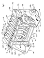
Fig. 2 is a left front perspective view of a baler plunger constructed in accordance with the principles of the present invention, with parts being removed to show mounting structure. -
Fig. 3 is a left front perspective view of the baler plunger shown inFig. 2 . -
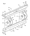
Fig. 4 is a right front perspective view of the support frame of the plunger. -
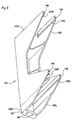
Fig. 5 is a left front perspective view of the right-hand plunger end section. -
Fig. 6 is a lower, left front perspective view of one of the plunger middle sections. - Referring now to
Fig. 1 , there is shown a baler 10 for forming large parallelepiped bales and including amain frame 12 supported on a tandem set of ground wheels 14. Adraft tongue 16 projects forwardly from the front of theframe 12 and is adapted for attachment to a towing vehicle such as an agricultural tractor, not shown. A baling chamber 18 includes parallel top andbottom walls 20 and 22, respectively, and opposite, parallel side walls 23, which are all arranged so that the baling chamber 18 has a square or rectangular cross section. Thebottom wall 22 is provided with acrop inlet 24 to which is coupled to the upper end of apre-compression chamber 26 in the form of a duct that curves upwardly and rearwardly from a crop pick-up 28. Located in the region between the pick-up 28 and thepre-compression chamber 26 is afeeder fork arrangement 30 that operates to positively move crop into the forward end of thechamber 26. Transversely spacedtines 32 of a pivotally mounted crop blocking fork 34 are selectively movable between a forwardly pivoted, crop-retaining position, wherein they extend over an upper edge of a back wall of thepre-compression chamber 26 and into thechamber 26 at a location adjacent thebaling chamber inlet 24, and a rearwardly pivoted crop-release position, (as shown) wherein they are removed from thepre-compression chamber 26 for permitting an accumulated charge of crop to be moved into the baling chamber 18 through operation of a stuffingfork 36 having transversely spaced tines that move down through slots provided in a front wall of thepre-compression chamber 26, and then sweep upwardly through thechamber 26 to move the charge of crop into the baling chamber 18. Appropriate actuators, not shown, are associated with the blocking fork 34 and stuffingfork 36, and are associated with controls that are sequenced to effect retraction of the blocking fork 34 and then operation of thestuffing fork 36 once the charge of crop has reached a preselected density as determined by a spring loaded,density sensing door 38. - Once the charge of crop has been moved into the baling chamber 18, it is moved rearwardly by operation of a
plunger drive 40 acting on aplunger 42 which compresses the charge of crop against a partially formedbale 44 and a completely formedbale 46 which has already been bound together by several transversely spaced loops of twine that have been placed there by operation of a twine tying arrangement comprising aneedle yoke 48, which is pivotally mounted and includes a plurality of laterally spacedneedles 50 for delivering twine to aknotting arrangement 52 mounted across the top wall 20 of the baling chamber 18, by way of slots (not shown) provided in thebottom wall 22 of the baling chamber 18. - The
plunger drive 40 may be of any known construction, but here is disclosed as including an extensible and retractablehydraulic drive cylinder 54 having its cylinder end anchored to theframe 12 by acoupling pin 56, and having its rod end pivotally coupled, as at apin 58, to acrank arm 60. Thecrank arm 60 is mounted for oscillating about a horizontal transverse axis defined by a pin 62 coupling the forward end of thecrank arm 60 to theframe 12. The rear end of thecrank arm 60 is pivotally coupled, as by acoupling pin 64, to the forward ends of a parallel pair of transversely spaced connectingrods 66 having their rear ends pivotally coupled to theplunger 42 byrespective coupling pins 68. Thehydraulic drive cylinder 54 is shown retracted inFig. 1 , this position corresponding to that where theplunger 42 is fully extended so that its rear face is located to the rear of theinlet 24 to the baling chamber 18, with extension of thecylinder 54 causing theplunger 42 to move forwardly to a position wherein the rear face of theplunger 42 is located forwardly of thecrop inlet 24. - Referring now also to
Figs. 2 ,3 and4 , it can be seen that theplunger 42 is of a modular construction and includes acarrier frame 70 including vertically spaced, parallel, top andbottom cross members top cross member 72 is defined by ahorizontal plate 76 having a top surface machined at its opposite ends to define mounting surfaces, with a rear edge of theplate 76 being joined along its length to a vertical rearrectangular plate 78, which defines the top of the T and includes a machined upper mounting surface. Lower corner regions at the opposite ends of thevertical plate 78 are removed to definenotches 80 having a purpose explained below. The stem of the T of thebottom cross member 74 is defined by ahorizontal plate 82 having a rear edge joined along its length to a vertical rearrectangular plate 84 disposed in co-planar relationship to thevertical plate 78 of thetop cross member 72 and defining the top of the T. Fore-and-aft extending,vertical mounting flanges 86 are joined to opposite ends of each of thehorizontal plate 82 and a lower part of thevertical plate 84. Extending between, and having opposite ends welded to, right and left end regions of the top andbottom cross members rod mounting plates mounting plates cylindrical bushings upright members mounting pins 68 for connecting the right and left connectingrods 66 to theplunger 42. - Referring now also to
Figs. 5 and6 , it can be seen that theplunger 42 includes right and leftplunger end sections middle plunger sections 100. The right and leftplunger end sections plunger end section 98 being shown in detail (seeFig. 5 ) and with it to be understood that any feature described as pertaining to the leftplunger end section 98 also pertains to the rightplunger end section 96. Theplunger end sections flat plates mounts plates axle mounts 106R, 106L are received within horizontal roller guide tracks 108 (seeFig. 1 ) provided in the side walls 23 of the baling chamber 18 so as to prevent theplunger 42 from cocking up or down within the baling chamber 18 during operation. Formed integrally with the upper edges of theplates shaped mounting pads vertical plates top cross member 72 of theframe 70 engaging thepads notches 80 permit thevertical plate 78 be located on top of themounting pads horizontal plate 76 are each provided with a pair ofmounting holes 110 that are disposed in axial alignment withholes 112 provided in a horizontal leg of each of thepads horizontal holes 113 provided in opposite ends of thevertical plate 78 are disposed in alignment with threadedbores 114 provided in the vertical leg of each of thepads cross member 72 of theframe 70 to theplunger end sections first mounting bolts 115 are inserted through the alignedholes second mounting bolts 116 are inserted into theholes 113 and threaded into thebores 114. Provided on each of theplates mounting flanges 86 is amounting pad 118 that contains a pair of horizontally disposedholes 120 that are aligned with a pair ofholes 122 provided in each of theflanges 86, withbolts 124 being received in the alignedholes nuts 126 tightened onto inner threaded ends so as to secure central lower regions of themodule end sections lower cross member 74 of theframe 70. - The
plates plunger end sections connection frame 70 that are each defined by top and bottom horizontal edges joined to a vertical edge. Respectively joined to this profile of theplates flanges flanges engaging surfaces plates U-shaped pockets U-shaped pockets engaging surfaces upper pockets bolt mounting holes 136 located in a triangular pattern, and an outer pair of outer bale corner-formingplunger teeth 138 are each provided with three mounting holes which are aligned with theholes 136 and respectively receive a set of threecarriage bolts 140 having threaded ends on whichnuts 142 are provided for holding theplunger teeth 138 in place so that they project upwardly and rearwardly from an upper rear corner of theflanges tooth 138 of theplunger end section 98 is shown. Theflanges mounting holes 144, with outer horizontalplunger knife segments 146 being respectively bolted to the bottom flange sections by bolts (not shown) projecting upwardly through holes provided in theknife segments 146 in alignment with theholes 144, with nuts being received on threaded upper ends of the bolts to hold theknife segments 146 in place. For the sake of simplicity, theknife segments 146 appear only inFig. 3 . - The
plunger middle sections 100 are spaced transversely from each other and from theplunger end sections needle clearance slots 148 for permitting passage of the twine-delivery needles 50 for delivering twine to thetwine knotting assembly 52 during tying of twine about a finishedbale 46. Eachplunger middle section 100 is fabricated as a casting defining transversely spaced right- and left-hand,vertical sides Fig. 6 ) joined by a verticalrear side 152 that defines a crop-engaging surface. The tops of each of thesides front regions bores 156. Thesides offset regions horizontal mounting pad 160 containing vertical threadedbores 162, with a horizontalplunger knife section 164 being secured to eachpad 160 by a pair of bolts (not shown). Thesides lower front regions front regions bores 156 are provided in the front surfaced of the thickenedlower front regions regions plunger section 100 is disposed in engagement with the rear surface of thevertical plate 78 of theupper cross member 72 of theframe 70, while the rear surface of the lower thickenedregions plunger section 100 are disposed in engagement with the rear surface of thevertical plate 84 of thelower cross member 74. Thevertical plate 78 of theupper cross member 72 is provided with a plurality ofhorizontal holes 168 that are respectively axially aligned with the upper set of threadedbores 156 of each of themiddle plunger sections 100, while thevertical plate 84 of thelower cross member 74 is provided with a plurality ofhorizontal holes 170 that are respectively axially aligned with the lower set of threadedbores 156 of each of theplunger sections 100. A plurality of bolts 172 project rearwardly through thehorizontal holes vertical plate 84 are not visible) thereby securing themiddle plunger sections 100 to theframe 70. - As can be seen in
Figs. 2 and3 , the upper rear region of themiddle plunger sections 100 are each provided with a triangular arrangement ofcarriage bolt holes 174, and a plurality ofmiddle plunger teeth 176 are respectively provided with matching sets of holes and receivemounting bolts 178 that project rearwardly through theholes 174 in theplunger sections 100 and in the matching holes provided in theplunger teeth 176, withnuts 180 being received on rear threaded ends of thebolts 178 so as to secure theteeth 176 in place where they project upwardly and rearwardly from themiddle plunger sections 100. - Thus, it will be appreciated that because the
plunger 42 uses cast sections in place of complex weldments, as used in the prior art, part count and complexity is reduced. Fewer and simpler plunger components reduce manufacturing costs by decreasing assembly time, reducing floor space requirements, and eliminating fabrication operations. Increased stiffness results in smaller plunger knife deflection and increased cutting efficiency during flake cutoff. Furthermore, if theplunger 42 is damaged, service toindividual plunger sections 96R, 96L or 100 can be performed often without removing theplunger 42 from the baling chamber 18. - Having described the preferred embodiment, it will become apparent that various modifications can be made without departing from the scope of the invention as defined in the accompanying claims.
Claims (8)
- A modular baler plunger (42) characterised by an upright carrier frame (70) extending transversely to a direction of intended reciprocation of said plunger (42), a plurality of separate upright plunger sections (96, 98, 100) being spaced transversely from each other so as to define a needle pathway between adjacent plunger sections (96, 98,100); said plunger sections (96, 98,100) including right and left, upright plunger end sections (96, 98) respectively releasably secured to opposite end regions of said carrier frame (70), and including a plurality of identical, parallel upright, plunger middle sections (100) having respective front end regions, as considered when the plunger (42) is used on a baler, releasably connected to said carrier frame (70).
- The modular baler plunger, as defined in claim 1, characterized in that said plunger sections (96, 98,100) are castings.
- The modular baler plunger, as defined in claim 1 or 2, characterized in that said plunger end sections (96, 98) are each provided with horizontal cylindrical receptacles (104R, 104L, 106R, 106L) for receiving guide roller axles.
- The modular baler plunger, as defined in one or more of the preceeding claims, characterized in that said carrier frame (70) includes vertically spaced, top and bottom cross members (72, 74); and said plunger end sections and said plunger (96, 98) middle sections (100) being bolted to said top and bottom cross members (72, 74).
- The modular baler plunger, as defined in one or more of the preceeding claims, characterized in that a top region of each of said plunger end sections (96, 98) is provided with a frame mounting pad (109R, 109L); and said top cross member (72) of said carrier frame (70) having opposite ends respectively in engagement with and secured to said mounting pad (109R, 109L).
- The modular baler plunger, as defined in one or more of the preceeding claims, characterized in that said mounting pad (109R, 109L, is L-shaped with long and short legs of the L being respectively disposed horizontally and vertically; and said upper cross member (72) having vertical and horizontal surfaces respectively engaging, and being secured to said legs of said mounting pad (109R, 109L).
- The modular baler plunger, as defined in one or more of the preceeding claims, characterized in that said right and left plunger end sections (96, 98) are respectively secured to right and left ends of said bottom cross member (74) of said carrier frame (70).
- The modular baler plunger (42) as defined in one or more of the preceeding claims, characterized in that said plunger middle sections (100) have respective front ends secured to said top and bottom cross members (72, 74).
Applications Claiming Priority (1)
| Application Number | Priority Date | Filing Date | Title |
|---|---|---|---|
| US12/410,938 US8069780B2 (en) | 2009-03-25 | 2009-03-25 | Modular baler plunger |
Publications (2)
| Publication Number | Publication Date |
|---|---|
| EP2232980A1 EP2232980A1 (en) | 2010-09-29 |
| EP2232980B1 true EP2232980B1 (en) | 2011-11-16 |
Family
ID=42227645
Family Applications (1)
| Application Number | Title | Priority Date | Filing Date |
|---|---|---|---|
| EP10154658A Not-in-force EP2232980B1 (en) | 2009-03-25 | 2010-02-25 | Modular baler plunger |
Country Status (3)
| Country | Link |
|---|---|
| US (1) | US8069780B2 (en) |
| EP (1) | EP2232980B1 (en) |
| AT (1) | ATE533352T1 (en) |
Cited By (1)
| Publication number | Priority date | Publication date | Assignee | Title |
|---|---|---|---|---|
| EP4035523A1 (en) | 2021-02-02 | 2022-08-03 | Usines Claas France S.A.S | Agricultural square baler |
Families Citing this family (8)
| Publication number | Priority date | Publication date | Assignee | Title |
|---|---|---|---|---|
| US8800255B2 (en) * | 2011-07-01 | 2014-08-12 | Cnh Industrial America Llc | Arrangement and control of precompression rolls in balers |
| US9854743B2 (en) * | 2012-05-31 | 2018-01-02 | Harvest Tec, Inc. | Device and method for measuring the moisture of hay in the pre-compression chamber of a rectangular baler |
| DE102014004920A1 (en) * | 2014-04-07 | 2015-10-08 | Usines Claas France S.A.S. | Quaderballenpresse |
| US9192104B1 (en) | 2014-05-07 | 2015-11-24 | Deere & Company | Lift link overload protection assembly |
| US9936646B2 (en) | 2014-11-12 | 2018-04-10 | Deere & Company | Light weight needle construction for delivering twine in a large square baler |
| US10785918B2 (en) * | 2017-05-18 | 2020-09-29 | Harvest Tec, Inc. | Device and method for measuring the properties of hay using near infrared spectroscopy on a large square baler |
| EP3646711B1 (en) * | 2018-11-02 | 2021-08-25 | CNH Industrial Belgium NV | Agricultural baler with frameless and weldless plunger |
| US10999974B2 (en) * | 2019-06-10 | 2021-05-11 | Deere & Company | Plunger scraper for reciprocating baler |
Family Cites Families (9)
| Publication number | Priority date | Publication date | Assignee | Title |
|---|---|---|---|---|
| DE206026C (en) | 1904-11-19 | 1909-01-25 | ||
| GB833650A (en) | 1955-04-26 | 1960-04-27 | Massey Ferguson Inc | Improvements in and relating to balers |
| DE3022631C1 (en) * | 1980-06-18 | 1982-02-11 | Gebrüder Welger GmbH & Co KG, 3340 Wolfenbüttel | Agricultural collecting press with filling opening on the underside of the press channel |
| US4627341A (en) * | 1985-09-06 | 1986-12-09 | New Holland, Inc. | Bale density control sensing apparatus and method |
| US4829756A (en) * | 1987-09-30 | 1989-05-16 | Hesston Corporation | Square baler having plunger cleanout means |
| US4945719A (en) * | 1989-09-01 | 1990-08-07 | Hay & Forage Industries | Square baler having plunger cleanout apparatus |
| US5945132A (en) * | 1997-01-30 | 1999-08-31 | Agriboard Industries | Apparatus for making compressed agricultural fiber structural board |
| DE20201417U1 (en) | 2002-01-30 | 2002-05-23 | Maschinenfabrik Bernard Krone GmbH, 48480 Spelle | baler |
| US7007599B2 (en) * | 2003-09-17 | 2006-03-07 | Deere & Company | Baler plunger drive load measurement pin offset from either connecting rod center line or horizontal mid-plane of baling chamber |
-
2009
- 2009-03-25 US US12/410,938 patent/US8069780B2/en active Active
-
2010
- 2010-02-25 AT AT10154658T patent/ATE533352T1/en active
- 2010-02-25 EP EP10154658A patent/EP2232980B1/en not_active Not-in-force
Cited By (2)
| Publication number | Priority date | Publication date | Assignee | Title |
|---|---|---|---|---|
| EP4035523A1 (en) | 2021-02-02 | 2022-08-03 | Usines Claas France S.A.S | Agricultural square baler |
| DE102021102348A1 (en) | 2021-02-02 | 2022-08-04 | Usines Claas France S.A.S. | Agricultural square baler |
Also Published As
| Publication number | Publication date |
|---|---|
| US8069780B2 (en) | 2011-12-06 |
| US20100242749A1 (en) | 2010-09-30 |
| EP2232980A1 (en) | 2010-09-29 |
| ATE533352T1 (en) | 2011-12-15 |
Similar Documents
| Publication | Publication Date | Title |
|---|---|---|
| EP2232980B1 (en) | Modular baler plunger | |
| WO2010100068A1 (en) | Mechanism for applying tension to a bale in the bale case of an agricultural baler | |
| US11044851B2 (en) | Adjustable stuffer chute | |
| US11667168B2 (en) | Axle arrangement for an agricultural baler | |
| GB1574097A (en) | Balers | |
| US20210243959A1 (en) | Agricultural baling machines | |
| US4258540A (en) | Agricultural baler | |
| US20140041536A1 (en) | Agricultural Square Baler | |
| EP3473080B1 (en) | Baler plunger guide system | |
| US12041884B2 (en) | Agricultural baling machines | |
| EP3760033B1 (en) | Needle frame yoke and arm assembly for agricultural machine | |
| EP4642218A1 (en) | Agricultural baler | |
| EP3809817B1 (en) | Agricultural baler with an axle arrangement | |
| US11547056B2 (en) | Frame assembly for an agricultural round baler | |
| US3450033A (en) | Unitized baling,bale accumulating,and transporting apparatus | |
| US12120986B2 (en) | Agricultural baling machines | |
| KR200442613Y1 (en) | Driving device for round baler | |
| WO2024261567A1 (en) | Agricultural baler | |
| TR2025006262T2 (en) | Separation panel for baler double chamber | |
| CA1067340A (en) | Bale shape control means |
Legal Events
| Date | Code | Title | Description |
|---|---|---|---|
| PUAI | Public reference made under article 153(3) epc to a published international application that has entered the european phase |
Free format text: ORIGINAL CODE: 0009012 |
|
| AK | Designated contracting states |
Kind code of ref document: A1 Designated state(s): AT BE BG CH CY CZ DE DK EE ES FI FR GB GR HR HU IE IS IT LI LT LU LV MC MK MT NL NO PL PT RO SE SI SK SM TR |
|
| AX | Request for extension of the european patent |
Extension state: AL BA RS |
|
| 17P | Request for examination filed |
Effective date: 20110329 |
|
| GRAP | Despatch of communication of intention to grant a patent |
Free format text: ORIGINAL CODE: EPIDOSNIGR1 |
|
| RIC1 | Information provided on ipc code assigned before grant |
Ipc: A01F 15/04 20060101AFI20110517BHEP |
|
| RIN1 | Information on inventor provided before grant (corrected) |
Inventor name: GNEWUCH, JOSHUA J. Inventor name: DEMULDER, CARL F. |
|
| GRAS | Grant fee paid |
Free format text: ORIGINAL CODE: EPIDOSNIGR3 |
|
| GRAA | (expected) grant |
Free format text: ORIGINAL CODE: 0009210 |
|
| AK | Designated contracting states |
Kind code of ref document: B1 Designated state(s): AT BE BG CH CY CZ DE DK EE ES FI FR GB GR HR HU IE IS IT LI LT LU LV MC MK MT NL NO PL PT RO SE SI SK SM TR |
|
| REG | Reference to a national code |
Ref country code: GB Ref legal event code: FG4D |
|
| REG | Reference to a national code |
Ref country code: CH Ref legal event code: EP |
|
| REG | Reference to a national code |
Ref country code: IE Ref legal event code: FG4D |
|
| REG | Reference to a national code |
Ref country code: DE Ref legal event code: R096 Ref document number: 602010000407 Country of ref document: DE Effective date: 20120112 |
|
| REG | Reference to a national code |
Ref country code: NL Ref legal event code: VDEP Effective date: 20111116 |
|
| LTIE | Lt: invalidation of european patent or patent extension |
Effective date: 20111116 |
|
| PG25 | Lapsed in a contracting state [announced via postgrant information from national office to epo] |
Ref country code: LT Free format text: LAPSE BECAUSE OF FAILURE TO SUBMIT A TRANSLATION OF THE DESCRIPTION OR TO PAY THE FEE WITHIN THE PRESCRIBED TIME-LIMIT Effective date: 20111116 Ref country code: IS Free format text: LAPSE BECAUSE OF FAILURE TO SUBMIT A TRANSLATION OF THE DESCRIPTION OR TO PAY THE FEE WITHIN THE PRESCRIBED TIME-LIMIT Effective date: 20120316 Ref country code: NO Free format text: LAPSE BECAUSE OF FAILURE TO SUBMIT A TRANSLATION OF THE DESCRIPTION OR TO PAY THE FEE WITHIN THE PRESCRIBED TIME-LIMIT Effective date: 20120216 |
|
| PG25 | Lapsed in a contracting state [announced via postgrant information from national office to epo] |
Ref country code: NL Free format text: LAPSE BECAUSE OF FAILURE TO SUBMIT A TRANSLATION OF THE DESCRIPTION OR TO PAY THE FEE WITHIN THE PRESCRIBED TIME-LIMIT Effective date: 20111116 Ref country code: SE Free format text: LAPSE BECAUSE OF FAILURE TO SUBMIT A TRANSLATION OF THE DESCRIPTION OR TO PAY THE FEE WITHIN THE PRESCRIBED TIME-LIMIT Effective date: 20111116 Ref country code: PT Free format text: LAPSE BECAUSE OF FAILURE TO SUBMIT A TRANSLATION OF THE DESCRIPTION OR TO PAY THE FEE WITHIN THE PRESCRIBED TIME-LIMIT Effective date: 20120316 Ref country code: HR Free format text: LAPSE BECAUSE OF FAILURE TO SUBMIT A TRANSLATION OF THE DESCRIPTION OR TO PAY THE FEE WITHIN THE PRESCRIBED TIME-LIMIT Effective date: 20111116 Ref country code: PL Free format text: LAPSE BECAUSE OF FAILURE TO SUBMIT A TRANSLATION OF THE DESCRIPTION OR TO PAY THE FEE WITHIN THE PRESCRIBED TIME-LIMIT Effective date: 20111116 Ref country code: SI Free format text: LAPSE BECAUSE OF FAILURE TO SUBMIT A TRANSLATION OF THE DESCRIPTION OR TO PAY THE FEE WITHIN THE PRESCRIBED TIME-LIMIT Effective date: 20111116 Ref country code: LV Free format text: LAPSE BECAUSE OF FAILURE TO SUBMIT A TRANSLATION OF THE DESCRIPTION OR TO PAY THE FEE WITHIN THE PRESCRIBED TIME-LIMIT Effective date: 20111116 Ref country code: BE Free format text: LAPSE BECAUSE OF FAILURE TO SUBMIT A TRANSLATION OF THE DESCRIPTION OR TO PAY THE FEE WITHIN THE PRESCRIBED TIME-LIMIT Effective date: 20111116 Ref country code: GR Free format text: LAPSE BECAUSE OF FAILURE TO SUBMIT A TRANSLATION OF THE DESCRIPTION OR TO PAY THE FEE WITHIN THE PRESCRIBED TIME-LIMIT Effective date: 20120217 |
|
| PG25 | Lapsed in a contracting state [announced via postgrant information from national office to epo] |
Ref country code: CY Free format text: LAPSE BECAUSE OF FAILURE TO SUBMIT A TRANSLATION OF THE DESCRIPTION OR TO PAY THE FEE WITHIN THE PRESCRIBED TIME-LIMIT Effective date: 20111116 |
|
| PG25 | Lapsed in a contracting state [announced via postgrant information from national office to epo] |
Ref country code: CZ Free format text: LAPSE BECAUSE OF FAILURE TO SUBMIT A TRANSLATION OF THE DESCRIPTION OR TO PAY THE FEE WITHIN THE PRESCRIBED TIME-LIMIT Effective date: 20111116 Ref country code: DK Free format text: LAPSE BECAUSE OF FAILURE TO SUBMIT A TRANSLATION OF THE DESCRIPTION OR TO PAY THE FEE WITHIN THE PRESCRIBED TIME-LIMIT Effective date: 20111116 Ref country code: EE Free format text: LAPSE BECAUSE OF FAILURE TO SUBMIT A TRANSLATION OF THE DESCRIPTION OR TO PAY THE FEE WITHIN THE PRESCRIBED TIME-LIMIT Effective date: 20111116 Ref country code: SK Free format text: LAPSE BECAUSE OF FAILURE TO SUBMIT A TRANSLATION OF THE DESCRIPTION OR TO PAY THE FEE WITHIN THE PRESCRIBED TIME-LIMIT Effective date: 20111116 Ref country code: BG Free format text: LAPSE BECAUSE OF FAILURE TO SUBMIT A TRANSLATION OF THE DESCRIPTION OR TO PAY THE FEE WITHIN THE PRESCRIBED TIME-LIMIT Effective date: 20120216 |
|
| PG25 | Lapsed in a contracting state [announced via postgrant information from national office to epo] |
Ref country code: RO Free format text: LAPSE BECAUSE OF FAILURE TO SUBMIT A TRANSLATION OF THE DESCRIPTION OR TO PAY THE FEE WITHIN THE PRESCRIBED TIME-LIMIT Effective date: 20111116 |
|
| REG | Reference to a national code |
Ref country code: AT Ref legal event code: MK05 Ref document number: 533352 Country of ref document: AT Kind code of ref document: T Effective date: 20111116 |
|
| PLBE | No opposition filed within time limit |
Free format text: ORIGINAL CODE: 0009261 |
|
| STAA | Information on the status of an ep patent application or granted ep patent |
Free format text: STATUS: NO OPPOSITION FILED WITHIN TIME LIMIT |
|
| PG25 | Lapsed in a contracting state [announced via postgrant information from national office to epo] |
Ref country code: MC Free format text: LAPSE BECAUSE OF NON-PAYMENT OF DUE FEES Effective date: 20120229 |
|
| 26N | No opposition filed |
Effective date: 20120817 |
|
| REG | Reference to a national code |
Ref country code: DE Ref legal event code: R097 Ref document number: 602010000407 Country of ref document: DE Effective date: 20120817 |
|
| PG25 | Lapsed in a contracting state [announced via postgrant information from national office to epo] |
Ref country code: AT Free format text: LAPSE BECAUSE OF FAILURE TO SUBMIT A TRANSLATION OF THE DESCRIPTION OR TO PAY THE FEE WITHIN THE PRESCRIBED TIME-LIMIT Effective date: 20111116 |
|
| PG25 | Lapsed in a contracting state [announced via postgrant information from national office to epo] |
Ref country code: MK Free format text: LAPSE BECAUSE OF FAILURE TO SUBMIT A TRANSLATION OF THE DESCRIPTION OR TO PAY THE FEE WITHIN THE PRESCRIBED TIME-LIMIT Effective date: 20111116 |
|
| PG25 | Lapsed in a contracting state [announced via postgrant information from national office to epo] |
Ref country code: ES Free format text: LAPSE BECAUSE OF FAILURE TO SUBMIT A TRANSLATION OF THE DESCRIPTION OR TO PAY THE FEE WITHIN THE PRESCRIBED TIME-LIMIT Effective date: 20120227 |
|
| PG25 | Lapsed in a contracting state [announced via postgrant information from national office to epo] |
Ref country code: FI Free format text: LAPSE BECAUSE OF FAILURE TO SUBMIT A TRANSLATION OF THE DESCRIPTION OR TO PAY THE FEE WITHIN THE PRESCRIBED TIME-LIMIT Effective date: 20111116 |
|
| PG25 | Lapsed in a contracting state [announced via postgrant information from national office to epo] |
Ref country code: MT Free format text: LAPSE BECAUSE OF FAILURE TO SUBMIT A TRANSLATION OF THE DESCRIPTION OR TO PAY THE FEE WITHIN THE PRESCRIBED TIME-LIMIT Effective date: 20111116 |
|
| PG25 | Lapsed in a contracting state [announced via postgrant information from national office to epo] |
Ref country code: TR Free format text: LAPSE BECAUSE OF FAILURE TO SUBMIT A TRANSLATION OF THE DESCRIPTION OR TO PAY THE FEE WITHIN THE PRESCRIBED TIME-LIMIT Effective date: 20111116 |
|
| PGFP | Annual fee paid to national office [announced via postgrant information from national office to epo] |
Ref country code: IE Payment date: 20140227 Year of fee payment: 5 |
|
| PG25 | Lapsed in a contracting state [announced via postgrant information from national office to epo] |
Ref country code: SM Free format text: LAPSE BECAUSE OF FAILURE TO SUBMIT A TRANSLATION OF THE DESCRIPTION OR TO PAY THE FEE WITHIN THE PRESCRIBED TIME-LIMIT Effective date: 20111116 Ref country code: LU Free format text: LAPSE BECAUSE OF NON-PAYMENT OF DUE FEES Effective date: 20120225 |
|
| PGFP | Annual fee paid to national office [announced via postgrant information from national office to epo] |
Ref country code: IT Payment date: 20140221 Year of fee payment: 5 |
|
| PG25 | Lapsed in a contracting state [announced via postgrant information from national office to epo] |
Ref country code: HU Free format text: LAPSE BECAUSE OF FAILURE TO SUBMIT A TRANSLATION OF THE DESCRIPTION OR TO PAY THE FEE WITHIN THE PRESCRIBED TIME-LIMIT Effective date: 20100225 |
|
| REG | Reference to a national code |
Ref country code: CH Ref legal event code: PL |
|
| GBPC | Gb: european patent ceased through non-payment of renewal fee |
Effective date: 20140225 |
|
| PG25 | Lapsed in a contracting state [announced via postgrant information from national office to epo] |
Ref country code: CH Free format text: LAPSE BECAUSE OF NON-PAYMENT OF DUE FEES Effective date: 20140228 Ref country code: LI Free format text: LAPSE BECAUSE OF NON-PAYMENT OF DUE FEES Effective date: 20140228 |
|
| PG25 | Lapsed in a contracting state [announced via postgrant information from national office to epo] |
Ref country code: GB Free format text: LAPSE BECAUSE OF NON-PAYMENT OF DUE FEES Effective date: 20140225 |
|
| REG | Reference to a national code |
Ref country code: IE Ref legal event code: MM4A |
|
| PG25 | Lapsed in a contracting state [announced via postgrant information from national office to epo] |
Ref country code: IT Free format text: LAPSE BECAUSE OF NON-PAYMENT OF DUE FEES Effective date: 20150225 |
|
| PG25 | Lapsed in a contracting state [announced via postgrant information from national office to epo] |
Ref country code: IE Free format text: LAPSE BECAUSE OF NON-PAYMENT OF DUE FEES Effective date: 20150225 |
|
| REG | Reference to a national code |
Ref country code: FR Ref legal event code: PLFP Year of fee payment: 7 |
|
| REG | Reference to a national code |
Ref country code: FR Ref legal event code: PLFP Year of fee payment: 8 |
|
| REG | Reference to a national code |
Ref country code: FR Ref legal event code: PLFP Year of fee payment: 9 |
|
| PGFP | Annual fee paid to national office [announced via postgrant information from national office to epo] |
Ref country code: FR Payment date: 20210223 Year of fee payment: 12 |
|
| PGFP | Annual fee paid to national office [announced via postgrant information from national office to epo] |
Ref country code: DE Payment date: 20210120 Year of fee payment: 12 |
|
| REG | Reference to a national code |
Ref country code: DE Ref legal event code: R119 Ref document number: 602010000407 Country of ref document: DE |
|
| PG25 | Lapsed in a contracting state [announced via postgrant information from national office to epo] |
Ref country code: FR Free format text: LAPSE BECAUSE OF NON-PAYMENT OF DUE FEES Effective date: 20220228 |
|
| PG25 | Lapsed in a contracting state [announced via postgrant information from national office to epo] |
Ref country code: DE Free format text: LAPSE BECAUSE OF NON-PAYMENT OF DUE FEES Effective date: 20220901 |