EP2231047B1 - Container for storing a cryosurgery device - Google Patents
Container for storing a cryosurgery device Download PDFInfo
- Publication number
- EP2231047B1 EP2231047B1 EP08862179A EP08862179A EP2231047B1 EP 2231047 B1 EP2231047 B1 EP 2231047B1 EP 08862179 A EP08862179 A EP 08862179A EP 08862179 A EP08862179 A EP 08862179A EP 2231047 B1 EP2231047 B1 EP 2231047B1
- Authority
- EP
- European Patent Office
- Prior art keywords
- depression
- base
- cryogen bottle
- container
- actuation assembly
- Prior art date
- Legal status (The legal status is an assumption and is not a legal conclusion. Google has not performed a legal analysis and makes no representation as to the accuracy of the status listed.)
- Not-in-force
Links
Images


Classifications
-
- A—HUMAN NECESSITIES
- A61—MEDICAL OR VETERINARY SCIENCE; HYGIENE
- A61B—DIAGNOSIS; SURGERY; IDENTIFICATION
- A61B50/00—Containers, covers, furniture or holders specially adapted for surgical or diagnostic appliances or instruments, e.g. sterile covers
- A61B50/30—Containers specially adapted for packaging, protecting, dispensing, collecting or disposing of surgical or diagnostic appliances or instruments
-
- A—HUMAN NECESSITIES
- A61—MEDICAL OR VETERINARY SCIENCE; HYGIENE
- A61B—DIAGNOSIS; SURGERY; IDENTIFICATION
- A61B18/00—Surgical instruments, devices or methods for transferring non-mechanical forms of energy to or from the body
- A61B18/02—Surgical instruments, devices or methods for transferring non-mechanical forms of energy to or from the body by cooling, e.g. cryogenic techniques
- A61B18/0218—Surgical instruments, devices or methods for transferring non-mechanical forms of energy to or from the body by cooling, e.g. cryogenic techniques with open-end cryogenic probe, e.g. for spraying fluid directly on tissue or via a tissue-contacting porous tip
-
- A—HUMAN NECESSITIES
- A61—MEDICAL OR VETERINARY SCIENCE; HYGIENE
- A61B—DIAGNOSIS; SURGERY; IDENTIFICATION
- A61B50/00—Containers, covers, furniture or holders specially adapted for surgical or diagnostic appliances or instruments, e.g. sterile covers
- A61B2050/005—Containers, covers, furniture or holders specially adapted for surgical or diagnostic appliances or instruments, e.g. sterile covers with a lid or cover
- A61B2050/0058—Containers, covers, furniture or holders specially adapted for surgical or diagnostic appliances or instruments, e.g. sterile covers with a lid or cover closable by translation
- A61B2050/006—Containers, covers, furniture or holders specially adapted for surgical or diagnostic appliances or instruments, e.g. sterile covers with a lid or cover closable by translation perpendicular to the lid plane, e.g. by a downward movement
-
- A—HUMAN NECESSITIES
- A61—MEDICAL OR VETERINARY SCIENCE; HYGIENE
- A61B—DIAGNOSIS; SURGERY; IDENTIFICATION
- A61B50/00—Containers, covers, furniture or holders specially adapted for surgical or diagnostic appliances or instruments, e.g. sterile covers
- A61B50/30—Containers specially adapted for packaging, protecting, dispensing, collecting or disposing of surgical or diagnostic appliances or instruments
- A61B2050/3008—Containers specially adapted for packaging, protecting, dispensing, collecting or disposing of surgical or diagnostic appliances or instruments having multiple compartments
-
- A—HUMAN NECESSITIES
- A61—MEDICAL OR VETERINARY SCIENCE; HYGIENE
- A61B—DIAGNOSIS; SURGERY; IDENTIFICATION
- A61B50/00—Containers, covers, furniture or holders specially adapted for surgical or diagnostic appliances or instruments, e.g. sterile covers
- A61B50/30—Containers specially adapted for packaging, protecting, dispensing, collecting or disposing of surgical or diagnostic appliances or instruments
- A61B2050/3015—Containers specially adapted for packaging, protecting, dispensing, collecting or disposing of surgical or diagnostic appliances or instruments transparent
-
- A—HUMAN NECESSITIES
- A61—MEDICAL OR VETERINARY SCIENCE; HYGIENE
- A61B—DIAGNOSIS; SURGERY; IDENTIFICATION
- A61B50/00—Containers, covers, furniture or holders specially adapted for surgical or diagnostic appliances or instruments, e.g. sterile covers
- A61B50/20—Holders specially adapted for surgical or diagnostic appliances or instruments
-
- A—HUMAN NECESSITIES
- A61—MEDICAL OR VETERINARY SCIENCE; HYGIENE
- A61B—DIAGNOSIS; SURGERY; IDENTIFICATION
- A61B50/00—Containers, covers, furniture or holders specially adapted for surgical or diagnostic appliances or instruments, e.g. sterile covers
- A61B50/30—Containers specially adapted for packaging, protecting, dispensing, collecting or disposing of surgical or diagnostic appliances or instruments
- A61B50/33—Trays
Definitions
- the present invention relates to a container configured to store a cryosurgery device and a cryosurgery kit.
- Cryosurgery devices are used for removing skin lesions such as warts. These devices have traditionally utilized liquid nitrogen as a medium for cooling down the tissue of a skin lesion to a temperature necessary to destroy the tissue.
- liquid nitrogen has a boiling point of -196°C and is therefore difficult to handle and administer safely
- cryosurgery devices employing a pressurized liquid refrigerant having a higher boiling point, e.g. - 20°C to -50°C have recently been developed and are now available for over-the-counter consumer use.
- cryosurgery devices typically employ an aerosol container, whose liquid refrigerant is directed through a conduit to a porous tip. The tip is then applied to the skin lesion for a prescribed period of time.
- cryosurgery device container which includes a base having compartments for storing all of the parts of a cryosurgery device, such as a cryogen bottle and applicator tips, as well as operating instructions.
- a cryogen bottle valve actuator and reservoir are integrated into the base.
- the container also includes a transparent door for the applicator tips and a transparent cover that fits on the base.
- the container has several advantages. First of all, a cryogen bottle valve actuator and reservoir integrated into a stable base allow the bottle to be actuated in a simple manner - with one hand, if need be - and allow refrigerant from the cryogen bottle to be stored safely and conveniently during use, without leakage or spillage.
- the transparent lid allows all of the device parts to be held in place and enables one to see all the device parts with the lid on the base.
- the compartment for the cryogen bottle is oriented in the base in such a manner, that the cryogen bottle is tilted back slightly and any logo or other information on the bottle is more visible to a customer in a store.
- cryosurgery kit which may include the above-mentioned container, e.g., the base and transparent cover, and also the above-mentioned items belonging to or associated with a cryosurgery device, e.g., a cryogen bottle, integrated valve actuator/reservoir, applicator tips, and operating instructions.
- a cryosurgery device e.g., a cryogen bottle, integrated valve actuator/reservoir, applicator tips, and operating instructions.
- Another example embodiment of the present invention is a container for a cryosurgery device which includes a cryogen bottle.
- the example container has a container body including an internal space sufficiently large to hold the cryogen bottle; a valve actuation assembly mechanically coupled to the container body, the valve actuation assembly configured to actuate a valve on the cryogen bottle; and a reservoir positioned relative to the valve actuation assembly so that the reservoir receives refrigerant from the cryogen bottle when the valve on the cryogen bottle is actuated using the valve actuation assembly.
- Some other example embodiments include a cryosurgery kit having a cryogen bottle; a container holding the cryogen bottle; and a valve actuation assembly mechanically coupled to the container, the valve actuation assembly configured to actuate a valve on the cryogen bottle.
- Additional example embodiments include a cryosurgery kit that has a cryogen bottle; a container holding the cryogen bottle; a valve actuation assembly mechanically coupled to the container, the valve actuation assembly configured to actuate a valve on the cryogen bottle; a liquid storage reservoir coupled to the container, the reservoir positioned relative to the valve actuation assembly so that the reservoir receives refrigerant from the cryogen bottle when the valve on the cryogen bottle is actuated using the valve actuation assembly; a transparent cover coupled to the base; a plurality of applicator tips; and an information booklet; wherein the container further comprises a base; the valve actuation assembly is an integral part of the base; the reservoir is an integral part of the base; the base includes a frustoconical-shaped depression, a rectangular-prism shaped depression having a substantially transparent door, and a slot-shaped depression; the cryogen bottle is situated in the frustoconical-shaped depression; the plurality of applicator tips are situated in the rectangular-shaped depression; and
- FIG. 1 is a perspective view of an example container for a cryosurgery device, according to an example embodiment of the present invention.
- the container 100 may include a container body 110 for storing a cryogen bottle 200 (see FIG. 8 ).
- the container 100 may also include a valve actuation assembly 120 mechanically coupled to the container body 110.
- a preferred method of mechanically coupling the valve actuation assembly to the container body 110 is integral molding, but adhesive bonding, friction-fitting, screws, etc., may also be employed.
- the valve actuation assembly 120 may be configured to actuate a valve 230 (see FIG. 9 ) of the cryogen bottle 200 and allow at least some of a refrigerant contained in the cryogen bottle 200 to be released.
- the valve actuation assembly 120 may be designed so as to only be able to mate with the cryogen bottle 200 and actuate the valve 230 at specific angular positions of the bottle 200, thereby reducing the chances of accidental release of refrigerant. In the example embodiments discussed with regard to FIGS. 9 and 10 , this is accomplished by providing arcuate keys 124 on the valve actuation assembly 120 that mate with slots 240 provided on the cryogen bottle 200. However, other ways of limiting actuation of valve 230 are possible.
- the container 100 additionally includes a reservoir 130 configured to hold at least some liquid refrigerant expelled from the cryogen bottle 200, after the valve 230 of the cryogen bottle 200 has been actuated via the valve actuation assembly 120.
- the container 100 also includes a base 140 and a cover 150.
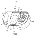
- FIG. 2 is a perspective view of an embodiment of the base 140 of the container 100 according to FIG. 1 .
- the valve actuation assembly 120 and/or the reservoir 130 may be formed integrally with the base 140.
- the base 140 may include a plurality of depressions for storing items belonging to or relating to the cryosurgery device.
- the base 140 contains a first depression 160 for storing the cryogen bottle 200.
- the first depression 160 may have an approximately frustoconical shape.
- the first depression 160 may have an approximately circular bottom 170 (see FIG.
- the base 140 may include a second depression 180, which may have approximately the shape of a rectangular prism and may be configured to store applicator tips 300 (see FIG. 11 ) for the cryosurgery device.
- the base 140 also includes a third depression 182, which may be arch-shaped and contiguous with the second depression 180.
- the base 140 may include a fourth depression 190, which may have the shape of an oblong slot and may be used, for example, to store an information booklet regarding the cryosurgery device.
- the base 140 may also include a shoulder 142, on which the cover 150 may rest, and ribs 144, which may aid in holding the cover in place.
- the base 140 may be injection-molded from one or more thermoplastic materials, such as polyethylene, polypropylene, or other polyolefins and polyolefin copolymers, nylons, polyesters, polyacetals, and polyurethanes.
- the base 140 may also be made of other suitable materials, such as styrenic resin polymers and copolymers, polyvinyl chloride, polyethylene terephthalate, polymethyl methacrylate and polycarbonate.
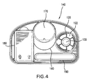
- FIG. 3 is a top view of the base 140 of FIG. 2 , according to an example embodiment of the present invention. From this view, it can be discerned that the bottom 170 of the frustoconical depression 160 is approximately circular in order for this depression 160 to receive a cylindrical cryogen bottle 200. In addition, it may also be discerned from this view that the reservoir 130 is approximately cylindrical in shape. Further with respect to FIG. 3 , the valve actuation assembly 120 includes projections 122, upon which arcuate keys 124 are situated. These keys 124 may cooperate with the valve 230 in the cryogen bottle 200 to release refrigerant into the reservoir 130. FIG. 4 shows a corresponding bottom view of the base 140.
- FIG. 5 is a sectional view of the example base of FIG. 3 , along line segment B-B.
- a sidewall 162 of the frustoconical depression 160 is oriented at an angle to a vertical direction
- the bottom 170 of the frustoconical depression 160 is oriented at an angle to a horizontal direction and approximately perpendicularly to the sidewall 162, so that the cylindrical cryogen bottle 200 supported in the depression 160 is tilted back at an angle to the vertical direction.
- This orientation of the cryogen bottle 200 may enable a consumer to more easily identify a brand label of the cryogen bottle 200 as the container 100 rests on a shelf in a store.
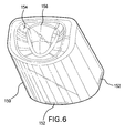
- FIG. 6 is a perspective view of an example cover 150 of the container of FIG. 1 .
- the cover 150 may be shaped approximately like a loaf of bread, i.e., having a cross section including two approximately parallel line segments joined on one side by a line segment approximately perpendicular to both, and joined on another side by an arcuate segment.
- the cover 150 may have any suitable shape, such as that of a cylinder, cone, pyramid, rectangular prism, etc.
- the cover 150 may be substantially transparent and may be made of materials, such as those mentioned above for the base 140, or other materials.
- the cover 150 may be slid onto the base 140 and come to rest on shoulder 142.
- the cover in order to effectively hold the cover 150 in place on shoulder 142, the cover may include ribs 152, which slide over and engage with the ribs 144 situated on the base 140.
- the ribs 152 and the ribs 144 may be continuous or intermittent.
- the cover 150 may be joined to the base 140 by other means, such as via hinges, latches, friction-fitting, etc.
- the cover 150 may additionally include a depression 154, out of which a protuberance 156 projects, or any other characteristic markings or designs.
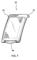
- FIG. 7 is a perspective view of an example door 184 for the second depression 180 in the base of FIG. 2 .
- the door 184 may be configured to close off the second depression 180, thereby allowing any items stored in the second depression 180 to be separated from other portions of the base 140.
- the door 184 may be transparent and may have an approximately rectangular shape.
- the door 184 may include cylindrical projections 185, which may be press-fit into recesses 186 on the base 140 and cooperate with these recesses 186 to form hinges.
- the door 184 may additionally include an arcuate lip 188.
- the arcuate lip 188 When the door 184 is in a closed position, the arcuate lip 188 may be situated over the depression 182 with a gap between the lip 188 and a base of the depression 182. In order to open the door 184, one must simply slide his or her finger into this gap and rotate the door 184 into an open position.
- the door may have side ribs and/or a front rib (not shown) configured to guide the door 184 into a proper seated position on the base 140, when the door 184 is closed.
- the lip 188 or any other part of the door 184 may include locking tabs (not shown) that engage with corresponding elements (not shown) situated on the base 140.
- FIG. 8 is a perspective view of an example cryogen bottle 200, which is stored in the frustoconical depression 160 of the container 100 when not in use.
- the cryogen bottle 200 may include a cylindrical portion 210, in which liquid and/or gaseous refrigerant is stored, and a hub 220, which may be attached to the cylindrical portion in a manner known to one skilled in the art.
- FIG. 9 is an enlarged perspective view of the example hub 220 of FIG. 8 .
- the hub 220 may include an aerosol valve 230 and slots 240, with which the arcuate keys 124 of the valve actuation assembly 120 may mate in order to actuate the aerosol valve 230.
- the aerosol valve 230 itself includes an annular actuating shoulder (not shown), which is situated inside the hub 220, directly beneath the slots 240.
- the hub 220 may further include aligning ribs 250, whose function will be explained with regard to FIG. 10 .
- the hub 220 may include threads 260, which may engage with the applicator tip 300 (see FIGS. 11 and 13 ).
- FIG. 10 is an enlarged perspective view of the example valve actuation assembly 120 of the container 100 shown in FIG. 1 .
- the valve actuation assembly 120 includes projections 122, upon which arcuate keys 124 are situated.
- the valve actuation assembly 120 may include aligning recesses 126, with which the aligning ribs 250 of the hub 220 may mate in order to bring the slots 240 of the hub 220 in alignment with the arcuate keys 124.
- a width and depth of the base 140 are both substantially greater than a diameter of the valve actuation assembly 120 and a diameter of the cryogen bottle 200.
- FIG. 11 is a perspective view of an example applicator tip 300, a plurality of which may be stored in the container 100 of FIG. 1 , in the depression 180, when the cryosurgery device is not in use.
- the applicator tip 300 is hollow and may have projections 310, which engage with the threads 260 of the hub 220 and allow the applicator tip 300 to be screwed onto the hub 220.
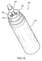
- FIG. 12 shows a perspective view of the cryogen bottle 200 with the applicator tip 300 screwed onto the hub 220.
- the applicator tip 300 When the applicator tip 300 is screwed onto the hub 220, a lower section 320 of the applicator tip 300 mates with the aerosol valve 230, thereby forming a route for refrigerant to flow to the distal end of the applicator tip 300 upon actuation of the aerosol valve 230.
- the applicator tip 300 may also include a center section 330 and an upper section 340.
- a porous cylindrical tip 350 may be mounted in the upper section 340. In the mounted state, the cylindrical tip 350 stands flush against circumferentially spaced vertical projections 360. These projections 360 form circumferential grooves 370, through which refrigerant may flow upon actuation of the aerosol valve 230.
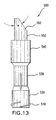
- FIG. 13 is a front view of an alternative embodiment of an applicator tip according to the present invention.
- the alternative applicator tip 500 shown in FIG. 13 is hollow and includes projections 510, which may engage with the threads 260 of the hub 220 and allow the applicator tip 500 to be screwed onto the hub 220.
- a lower section 520 of the applicator tip 500 mates with the aerosol valve 230, thereby forming a route for refrigerant to flow to the distal end of the applicator tip 500 upon actuation of the aerosol valve 230.
- the applicator tip 500 may also include a center section 530 and an upper section 540.
- a porous, partially cylindrical tip 550 may be mounted in the upper section 540.
- the partially cylindrical tip 550 of applicator tip includes a face 552 oriented at an angle ⁇ to an axial direction of the tip 550.
- the angle ⁇ is preferably 33° or less.
- FIG. 14 is a perspective view of an example cryosurgery kit according to an example embodiment of the present invention.
- the cryosurgery kit may include the container 100, which itself may include the base 140 and the cover 150.
- the cryosurgery kit may also include the cryogen bottle 160, a plurality of applicator tips 300, the valve actuation assembly 120, the reservoir 130, the door 184, and an information booklet 400.
- the cryogen bottle 200 is situated in the depression 160 such that the cryogen bottle 200 is tilted back from a vertical position.
- Applicator tips 300 may be stored in the second depression 180.
- the door 184 may aid in keeping the applicator tips 300 from inadvertently spilling out of the second depression 180 and may prevent excess dirt, dust, moisture or other foreign material from settling on the applicator tips 300.
- One applicator tip 300 may also be pre-attached to the hub 220 of the cryogen bottle 200, in order to show proper assembly.
- the information booklet 400 may be stored in the fourth depression 190.
- a card (not shown) including a brand name, picture, diagram or other product information, including treatment instructions and recommendations, may be inserted or mounted in the fourth depression 190.
- the cryosurgery device stored in container 100 may be used, for example, to treat warts, skin tags and other skin lesions.
- the cryogen bottle 200 is removed from the frustoconical depression 160 of base 140 and placed in an upright position.
- An applicator tip 300 is then removed from the second depression 180 in the base 140 and screwed onto the hub 220 of the cryogen bottle 200 via threads 260.
- the cryogen bottle/applicator tip assembly is then turned upside down and caused to mate with the valve actuation assembly 120. In so doing, the cryogen bottle 200 is rotated until the aligning ribs 250 of the hub 220 are in alignment with, and engage with, the aligning recesses 126 of the valve actuation assembly 120.
- the arcuate keys 124 of the valve actuation assembly 120 and the slots 240 of the hub 220 are positioned relative to the aligning recesses 126 and the aligning ribs 250, respectively, in such a manner, that the arcuate keys 124 engage with the slots 240 simultaneously to the aligning ribs 250 engaging with the aligning recesses 126.
- a downward force is then applied by hand to the cryogen bottle 200 for a time period of, for example, approximately 2 to 3 seconds.
- the width and depth of the base 140 are substantially greater than the diameter of the valve actuation assembly and the diameter of the cryogen bottle 200, which may allow the base 140 to remain stable and not tip as the downward force is applied to the valve actuation assembly 120.
- the arcuate keys 124 press down on the annular shoulder of the valve 230, situated directly beneath the slots 240, and actuate the valve 230.
- the valve 230 is opened and refrigerant from the cryogen bottle 200 enters the applicator tip 300 and travels through the lower and center sections 320, 330 of the applicator tip 300.
- the refrigerant reaches the upper section 340 of the applicator tip 300, the refrigerant is channeled through grooves 370 onto the porous cylindrical tip 350 and into the reservoir 130.
- the tip 350 is cooled to a temperature of approximately -20°C or less.
- the force is then removed from the cryogen bottle 200, thereby causing the aerosol valve 230 to close and the flow of refrigerant to cease.
- the cryogen bottle/applicator tip assembly is then removed from the valve actuation assembly 120, and the applicator tip 300 is applied to a wart, skin tag or other skin lesion for an appropriate period of time.
- the above-mentioned container 100 having base 140 with depressions for storage and a valve actuation assembly 120 for operation has several advantages. First of all, the parts of the cryosurgery device are stored in one place. In addition, the valve actuation assembly 120 and reservoir 130 are connected to and/or integrated into a stable base 140 that will remain steady even when a non-vertical force component is introduced into the cryogen bottle 200 during actuation of aerosol valve 230. Furthermore, the reservoir 130 ensures that the refrigerant expelled from the cryogen bottle 200 is retained near the porous cylindrical tip 350 of the applicator tip 300, efficiently utilized and not inadvertently spilled.
- no applicator tip 300 needs to be screwed onto the hub 220 of the cryogen bottle 200.
- refrigerant from the cryogen bottle 200 may simply be injected directly into the reservoir, and a swab may be subsequently immersed in a resulting pool of refrigerant in the reservoir 130.
- the swab may be an applicator tip 300 that has not been chilled by refrigerant as described above, but is manually inserted into reservoir disconnected from the cryogen bottle 200 After a prescribed period of time, the swab may be removed from the reservoir and applied to a wart, skin tag or other skin lesion.
Description
- The present invention relates to a container configured to store a cryosurgery device and a cryosurgery kit.
- Cryosurgery devices are used for removing skin lesions such as warts. These devices have traditionally utilized liquid nitrogen as a medium for cooling down the tissue of a skin lesion to a temperature necessary to destroy the tissue. However, since liquid nitrogen has a boiling point of -196°C and is therefore difficult to handle and administer safely, cryosurgery devices employing a pressurized liquid refrigerant having a higher boiling point, e.g. - 20°C to -50°C, have recently been developed and are now available for over-the-counter consumer use.
- These more recent cryosurgery devices typically employ an aerosol container, whose liquid refrigerant is directed through a conduit to a porous tip. The tip is then applied to the skin lesion for a prescribed period of time.
- The
US Patent Application 2006/0189968 A1 discloses such a cryosurgery device However, the manner in which the refrigerant is transferred from the aerosol container to the tip may not sufficiently limit the loss of the refrigerant during such transfer and may not sufficiently prevent accidental release of the refrigerant. -
-
FIG. 1 is an exploded view of an example container for a cryosurgery device, according to an example embodiment of the present invention. -
FIG. 2 is a perspective view of an example base of the example container shown inFIG. 1 , according to an example embodiment of the present invention. -
FIG. 3 is a top view of the example base ofFIG. 2 , according to an example embodiment of the present invention. -
FIG. 4 is a bottom view of the example base ofFIG. 2 , according to an example embodiment of the present invention. -
FIG. 5 is a representation of section B-B of the example base ofFIG. 3 , viewed in the direction of the arrows. -
FIG. 6 is a perspective view of an example cover of the container ofFIG. 1 , according to an example embodiment of the present invention. -
FIG. 7 is a perspective view of an example door for a depression in the base ofFIG. 2 , according to an example embodiment of the present invention. -
FIG. 8 is a perspective view of an example cryogen bottle according to an example embodiment of the present invention. -
FIG. 9 is an enlarged perspective view of an example hub situated at the top of the cryogen bottle ofFIG. 8 , according to an example embodiment of the present invention. -
FIG. 10 is an enlarged perspective view of an example valve actuation assembly of the container ofFIG. 1 , according to an example embodiment of the present invention. -
FIG. 11 is a perspective view of an example applicator tip that may be stored in the container ofFIG. 1 , according to an example embodiment of the present invention. -
FIG. 12 is a perspective view of the example applicator tip ofFIG. 11 attached to the cryogen bottle ofFIG. 8 , according to an example embodiment of the present invention. -
FIG. 13 is a front view of an alternative embodiment of an applicator tip according to the present invention. -
FIG. 14 is a perspective view of an example cryosurgery kit according to an example embodiment of the present invention. - The inventors of the present application have recognized that there is a need for a cryosurgery device container that efficiently stores parts belonging to a cryosurgery device and also provides for safe and efficient use of the device. The invention is as defined by the appended claims.
- One example embodiment of the present invention is a cryosurgery device container which includes a base having compartments for storing all of the parts of a cryosurgery device, such as a cryogen bottle and applicator tips, as well as operating instructions. In addition, a cryogen bottle valve actuator and reservoir are integrated into the base. The container also includes a transparent door for the applicator tips and a transparent cover that fits on the base. The container has several advantages. First of all, a cryogen bottle valve actuator and reservoir integrated into a stable base allow the bottle to be actuated in a simple manner - with one hand, if need be - and allow refrigerant from the cryogen bottle to be stored safely and conveniently during use, without leakage or spillage. In addition, the transparent lid allows all of the device parts to be held in place and enables one to see all the device parts with the lid on the base. Furthermore, the compartment for the cryogen bottle is oriented in the base in such a manner, that the cryogen bottle is tilted back slightly and any logo or other information on the bottle is more visible to a customer in a store.
- Another example embodiment of the present invention is a cryosurgery kit which may include the above-mentioned container, e.g., the base and transparent cover, and also the above-mentioned items belonging to or associated with a cryosurgery device, e.g., a cryogen bottle, integrated valve actuator/reservoir, applicator tips, and operating instructions.
- Another example embodiment of the present invention is a container for a cryosurgery device which includes a cryogen bottle. The example container has a container body including an internal space sufficiently large to hold the cryogen bottle; a valve actuation assembly mechanically coupled to the container body, the valve actuation assembly configured to actuate a valve on the cryogen bottle; and a reservoir positioned relative to the valve actuation assembly so that the reservoir receives refrigerant from the cryogen bottle when the valve on the cryogen bottle is actuated using the valve actuation assembly.
- Some other example embodiments include a cryosurgery kit having a cryogen bottle; a container holding the cryogen bottle; and a valve actuation assembly mechanically coupled to the container, the valve actuation assembly configured to actuate a valve on the cryogen bottle.
- In another example embodiment of the present invention, a container for a cryosurgery device that includes a cryogen bottle includes a container body containing an internal space sufficiently large to hold the cryogen bottle; a valve actuation assembly mechanically coupled to the container body, the valve actuation assembly configured to actuate a valve on the cryogen bottle; a reservoir positioned relative to the valve actuation assembly so that the reservoir receives refrigerant from the cryogen bottle when the valve on the cryogen bottle is actuated using the valve actuation assembly; a base, wherein the valve actuation assembly and the reservoir are integral parts of the base; and a cover configured to form a closed volume with the base, the closed volume dimensioned large enough to contain the cryogen bottle; wherein the reservoir is situated beneath the valve actuation assembly; the base includes a first depression into which the cryogen bottle may be placed; the first depression is approximately frustoconical; the first depression has an approximately circular bottom and is oriented such that when the cryogen bottle is placed in the first depression, the cryogen bottle is tilted back from a vertical position; the base includes a second depression in which applicator tips may be stored; the second depression has approximately a shape of a rectangular prism; the base includes a door that closes off the second depression when the door is in a closed position; the cover is substantially transparent; the base includes a third depression contiguous with the second depression; the third depression has approximately a shape of an arch; and the base includes a fourth depression having a shape of an oblong slot.
- Additional example embodiments include a cryosurgery kit that has a cryogen bottle; a container holding the cryogen bottle; a valve actuation assembly mechanically coupled to the container, the valve actuation assembly configured to actuate a valve on the cryogen bottle; a liquid storage reservoir coupled to the container, the reservoir positioned relative to the valve actuation assembly so that the reservoir receives refrigerant from the cryogen bottle when the valve on the cryogen bottle is actuated using the valve actuation assembly; a transparent cover coupled to the base; a plurality of applicator tips; and an information booklet; wherein the container further comprises a base; the valve actuation assembly is an integral part of the base; the reservoir is an integral part of the base; the base includes a frustoconical-shaped depression, a rectangular-prism shaped depression having a substantially transparent door, and a slot-shaped depression; the cryogen bottle is situated in the frustoconical-shaped depression; the plurality of applicator tips are situated in the rectangular-shaped depression; and the information booklet is situated in the slot-shaped depression.
- Other features and aspects of the present invention will become more fully apparent from the following detailed description of some example embodiments, the appended claims and the accompanying drawings.
-
FIG. 1 is a perspective view of an example container for a cryosurgery device, according to an example embodiment of the present invention. Thecontainer 100 may include acontainer body 110 for storing a cryogen bottle 200 (seeFIG. 8 ). Thecontainer 100 may also include avalve actuation assembly 120 mechanically coupled to thecontainer body 110. A preferred method of mechanically coupling the valve actuation assembly to thecontainer body 110 is integral molding, but adhesive bonding, friction-fitting, screws, etc., may also be employed. Thevalve actuation assembly 120 may be configured to actuate a valve 230 (seeFIG. 9 ) of thecryogen bottle 200 and allow at least some of a refrigerant contained in thecryogen bottle 200 to be released. Thevalve actuation assembly 120 may be designed so as to only be able to mate with thecryogen bottle 200 and actuate thevalve 230 at specific angular positions of thebottle 200, thereby reducing the chances of accidental release of refrigerant. In the example embodiments discussed with regard toFIGS. 9 and10 , this is accomplished by providingarcuate keys 124 on thevalve actuation assembly 120 that mate withslots 240 provided on thecryogen bottle 200. However, other ways of limiting actuation ofvalve 230 are possible. Further with respect toFIG. 1 , thecontainer 100 additionally includes areservoir 130 configured to hold at least some liquid refrigerant expelled from thecryogen bottle 200, after thevalve 230 of thecryogen bottle 200 has been actuated via thevalve actuation assembly 120. Thecontainer 100 also includes abase 140 and acover 150. -
FIG. 2 is a perspective view of an embodiment of thebase 140 of thecontainer 100 according toFIG. 1 . As an initial matter, it should be pointed out that in this figure and all proceeding figures, identical parts will be assigned the same reference numerals. In this embodiment, thevalve actuation assembly 120 and/or thereservoir 130 may be formed integrally with thebase 140. Thebase 140 may include a plurality of depressions for storing items belonging to or relating to the cryosurgery device. Specifically, thebase 140 contains afirst depression 160 for storing thecryogen bottle 200. Thefirst depression 160 may have an approximately frustoconical shape. In addition, thefirst depression 160 may have an approximately circular bottom 170 (seeFIG. 3 ) and may be oriented in such a manner that when thecryogen bottle 200 is placed into thefirst depression 160, thecryogen bottle 200 is tilted back from a vertical position. Further with regard toFIG. 2 , thebase 140 may include asecond depression 180, which may have approximately the shape of a rectangular prism and may be configured to store applicator tips 300 (seeFIG. 11 ) for the cryosurgery device. Thebase 140 also includes athird depression 182, which may be arch-shaped and contiguous with thesecond depression 180. Furthermore, thebase 140 may include afourth depression 190, which may have the shape of an oblong slot and may be used, for example, to store an information booklet regarding the cryosurgery device. Thebase 140 may also include ashoulder 142, on which thecover 150 may rest, andribs 144, which may aid in holding the cover in place. Typically, thebase 140 may be injection-molded from one or more thermoplastic materials, such as polyethylene, polypropylene, or other polyolefins and polyolefin copolymers, nylons, polyesters, polyacetals, and polyurethanes. However, thebase 140 may also be made of other suitable materials, such as styrenic resin polymers and copolymers, polyvinyl chloride, polyethylene terephthalate, polymethyl methacrylate and polycarbonate. -
FIG. 3 is a top view of thebase 140 ofFIG. 2 , according to an example embodiment of the present invention. From this view, it can be discerned that thebottom 170 of thefrustoconical depression 160 is approximately circular in order for thisdepression 160 to receive acylindrical cryogen bottle 200. In addition, it may also be discerned from this view that thereservoir 130 is approximately cylindrical in shape. Further with respect toFIG. 3 , thevalve actuation assembly 120 includesprojections 122, upon whicharcuate keys 124 are situated. Thesekeys 124 may cooperate with thevalve 230 in thecryogen bottle 200 to release refrigerant into thereservoir 130.FIG. 4 shows a corresponding bottom view of thebase 140. -
FIG. 5 is a sectional view of the example base ofFIG. 3 , along line segment B-B. As is apparent from this view, asidewall 162 of thefrustoconical depression 160 is oriented at an angle to a vertical direction, and thebottom 170 of thefrustoconical depression 160 is oriented at an angle to a horizontal direction and approximately perpendicularly to thesidewall 162, so that thecylindrical cryogen bottle 200 supported in thedepression 160 is tilted back at an angle to the vertical direction. This orientation of thecryogen bottle 200 may enable a consumer to more easily identify a brand label of thecryogen bottle 200 as thecontainer 100 rests on a shelf in a store. -
FIG. 6 is a perspective view of anexample cover 150 of the container ofFIG. 1 . In this example embodiment, thecover 150 may be shaped approximately like a loaf of bread, i.e., having a cross section including two approximately parallel line segments joined on one side by a line segment approximately perpendicular to both, and joined on another side by an arcuate segment. However, thecover 150 may have any suitable shape, such as that of a cylinder, cone, pyramid, rectangular prism, etc. Thecover 150 may be substantially transparent and may be made of materials, such as those mentioned above for thebase 140, or other materials. Thecover 150 may be slid onto thebase 140 and come to rest onshoulder 142. In this embodiment, in order to effectively hold thecover 150 in place onshoulder 142, the cover may includeribs 152, which slide over and engage with theribs 144 situated on thebase 140. In addition, theribs 152 and theribs 144 may be continuous or intermittent. However, thecover 150 may be joined to thebase 140 by other means, such as via hinges, latches, friction-fitting, etc. Thecover 150 may additionally include adepression 154, out of which aprotuberance 156 projects, or any other characteristic markings or designs. -
FIG. 7 is a perspective view of anexample door 184 for thesecond depression 180 in the base ofFIG. 2 . Thedoor 184 may be configured to close off thesecond depression 180, thereby allowing any items stored in thesecond depression 180 to be separated from other portions of thebase 140. Thedoor 184 may be transparent and may have an approximately rectangular shape. In order to be able to attach thedoor 184 to thebase 140 and pivot thedoor 184 with respect to thebase 140, thedoor 184 may includecylindrical projections 185, which may be press-fit intorecesses 186 on thebase 140 and cooperate with theserecesses 186 to form hinges. Thedoor 184 may additionally include anarcuate lip 188. When thedoor 184 is in a closed position, thearcuate lip 188 may be situated over thedepression 182 with a gap between thelip 188 and a base of thedepression 182. In order to open thedoor 184, one must simply slide his or her finger into this gap and rotate thedoor 184 into an open position. In addition, the door may have side ribs and/or a front rib (not shown) configured to guide thedoor 184 into a proper seated position on thebase 140, when thedoor 184 is closed. Furthermore, thelip 188 or any other part of thedoor 184 may include locking tabs (not shown) that engage with corresponding elements (not shown) situated on thebase 140. -
FIG. 8 is a perspective view of anexample cryogen bottle 200, which is stored in thefrustoconical depression 160 of thecontainer 100 when not in use. Thecryogen bottle 200 may include acylindrical portion 210, in which liquid and/or gaseous refrigerant is stored, and ahub 220, which may be attached to the cylindrical portion in a manner known to one skilled in the art. -
FIG. 9 is an enlarged perspective view of theexample hub 220 ofFIG. 8 . Thehub 220 may include anaerosol valve 230 andslots 240, with which thearcuate keys 124 of thevalve actuation assembly 120 may mate in order to actuate theaerosol valve 230. Theaerosol valve 230 itself includes an annular actuating shoulder (not shown), which is situated inside thehub 220, directly beneath theslots 240. Thehub 220 may further include aligningribs 250, whose function will be explained with regard toFIG. 10 . In addition, thehub 220 may includethreads 260, which may engage with the applicator tip 300 (seeFIGS. 11 and13 ). -
FIG. 10 is an enlarged perspective view of the examplevalve actuation assembly 120 of thecontainer 100 shown inFIG. 1 . As mentioned with regard toFIG. 3 , thevalve actuation assembly 120 includesprojections 122, upon whicharcuate keys 124 are situated. In addition, thevalve actuation assembly 120 may include aligningrecesses 126, with which the aligningribs 250 of thehub 220 may mate in order to bring theslots 240 of thehub 220 in alignment with thearcuate keys 124. Furthermore, as is apparent fromFIGS. 1 to 4 and8 to 10 , a width and depth of the base 140 are both substantially greater than a diameter of thevalve actuation assembly 120 and a diameter of thecryogen bottle 200. -
FIG. 11 is a perspective view of anexample applicator tip 300, a plurality of which may be stored in thecontainer 100 ofFIG. 1 , in thedepression 180, when the cryosurgery device is not in use. Theapplicator tip 300 is hollow and may haveprojections 310, which engage with thethreads 260 of thehub 220 and allow theapplicator tip 300 to be screwed onto thehub 220.FIG. 12 shows a perspective view of thecryogen bottle 200 with theapplicator tip 300 screwed onto thehub 220. When theapplicator tip 300 is screwed onto thehub 220, alower section 320 of theapplicator tip 300 mates with theaerosol valve 230, thereby forming a route for refrigerant to flow to the distal end of theapplicator tip 300 upon actuation of theaerosol valve 230. Theapplicator tip 300 may also include acenter section 330 and anupper section 340. A porouscylindrical tip 350 may be mounted in theupper section 340. In the mounted state, thecylindrical tip 350 stands flush against circumferentially spacedvertical projections 360. Theseprojections 360 formcircumferential grooves 370, through which refrigerant may flow upon actuation of theaerosol valve 230. -
FIG. 13 is a front view of an alternative embodiment of an applicator tip according to the present invention. Similarly toapplicator tip 300, thealternative applicator tip 500 shown inFIG. 13 is hollow and includesprojections 510, which may engage with thethreads 260 of thehub 220 and allow theapplicator tip 500 to be screwed onto thehub 220. When theapplicator tip 500 is screwed onto thehub 220, alower section 520 of theapplicator tip 500 mates with theaerosol valve 230, thereby forming a route for refrigerant to flow to the distal end of theapplicator tip 500 upon actuation of theaerosol valve 230. Theapplicator tip 500 may also include acenter section 530 and anupper section 540. A porous, partiallycylindrical tip 550 may be mounted in theupper section 540. In contrast to thecylindrical tip 350 ofapplicator tip 300, the partiallycylindrical tip 550 of applicator tip includes aface 552 oriented at an angle α to an axial direction of thetip 550. The angle α is preferably 33° or less. -
FIG. 14 is a perspective view of an example cryosurgery kit according to an example embodiment of the present invention. The cryosurgery kit may include thecontainer 100, which itself may include thebase 140 and thecover 150. The cryosurgery kit may also include thecryogen bottle 160, a plurality ofapplicator tips 300, thevalve actuation assembly 120, thereservoir 130, thedoor 184, and aninformation booklet 400. Thecryogen bottle 200 is situated in thedepression 160 such that thecryogen bottle 200 is tilted back from a vertical position.Applicator tips 300 may be stored in thesecond depression 180. Thedoor 184 may aid in keeping theapplicator tips 300 from inadvertently spilling out of thesecond depression 180 and may prevent excess dirt, dust, moisture or other foreign material from settling on theapplicator tips 300. Oneapplicator tip 300 may also be pre-attached to thehub 220 of thecryogen bottle 200, in order to show proper assembly. Theinformation booklet 400 may be stored in thefourth depression 190. In addition, a card (not shown) including a brand name, picture, diagram or other product information, including treatment instructions and recommendations, may be inserted or mounted in thefourth depression 190. - The cryosurgery device stored in
container 100 may be used, for example, to treat warts, skin tags and other skin lesions. In operation of this device, thecryogen bottle 200 is removed from thefrustoconical depression 160 ofbase 140 and placed in an upright position. Anapplicator tip 300 is then removed from thesecond depression 180 in thebase 140 and screwed onto thehub 220 of thecryogen bottle 200 viathreads 260. The cryogen bottle/applicator tip assembly is then turned upside down and caused to mate with thevalve actuation assembly 120. In so doing, thecryogen bottle 200 is rotated until the aligningribs 250 of thehub 220 are in alignment with, and engage with, the aligningrecesses 126 of thevalve actuation assembly 120. Thearcuate keys 124 of thevalve actuation assembly 120 and theslots 240 of thehub 220 are positioned relative to the aligningrecesses 126 and the aligningribs 250, respectively, in such a manner, that thearcuate keys 124 engage with theslots 240 simultaneously to the aligningribs 250 engaging with the aligning recesses 126. A downward force is then applied by hand to thecryogen bottle 200 for a time period of, for example, approximately 2 to 3 seconds. As mentioned with regard toFIG. 10 , the width and depth of the base 140 are substantially greater than the diameter of the valve actuation assembly and the diameter of thecryogen bottle 200, which may allow the base 140 to remain stable and not tip as the downward force is applied to thevalve actuation assembly 120. During application of the force, thearcuate keys 124 press down on the annular shoulder of thevalve 230, situated directly beneath theslots 240, and actuate thevalve 230. As a result, thevalve 230 is opened and refrigerant from thecryogen bottle 200 enters theapplicator tip 300 and travels through the lower andcenter sections applicator tip 300. When the refrigerant reaches theupper section 340 of theapplicator tip 300, the refrigerant is channeled throughgrooves 370 onto the porouscylindrical tip 350 and into thereservoir 130. As the refrigerant flows onto thecylindrical tip 350, thetip 350 is cooled to a temperature of approximately -20°C or less. The force is then removed from thecryogen bottle 200, thereby causing theaerosol valve 230 to close and the flow of refrigerant to cease. The cryogen bottle/applicator tip assembly is then removed from thevalve actuation assembly 120, and theapplicator tip 300 is applied to a wart, skin tag or other skin lesion for an appropriate period of time. - The above-mentioned
container 100 havingbase 140 with depressions for storage and avalve actuation assembly 120 for operation has several advantages. First of all, the parts of the cryosurgery device are stored in one place. In addition, thevalve actuation assembly 120 andreservoir 130 are connected to and/or integrated into astable base 140 that will remain steady even when a non-vertical force component is introduced into thecryogen bottle 200 during actuation ofaerosol valve 230. Furthermore, thereservoir 130 ensures that the refrigerant expelled from thecryogen bottle 200 is retained near the porouscylindrical tip 350 of theapplicator tip 300, efficiently utilized and not inadvertently spilled. - In an alternative embodiment of the cryosurgery device, no
applicator tip 300 needs to be screwed onto thehub 220 of thecryogen bottle 200. Instead, refrigerant from thecryogen bottle 200 may simply be injected directly into the reservoir, and a swab may be subsequently immersed in a resulting pool of refrigerant in thereservoir 130. In certain embodiments, the swab may be anapplicator tip 300 that has not been chilled by refrigerant as described above, but is manually inserted into reservoir disconnected from thecryogen bottle 200 After a prescribed period of time, the swab may be removed from the reservoir and applied to a wart, skin tag or other skin lesion. - The foregoing description discloses only exemplary embodiments of the invention. Modification of the above-disclosed apparatus which falls within the scope of the invention will be readily apparent to those of ordinary skill in the art. Accordingly, while the present invention has been disclosed in connection with exemplary embodiments thereof, it should be understood that other embodiments may fall within the scope of the invention, as defined by the following claims.
Claims (14)
- A container (100) for a cryosurgery device which includes a cryogen bottle (200), comprising:a container body (110) including an internal space configured to hold the cryogen bottle (200); a valve actuation assembly (120) mechanically coupled to the container body (110), the valve actuation assembly (120) configured to actuate a valve (230) on the cryogen bottle (200); a reservoir (130) positioned relative to the valve actuation assembly (120), the reservoir (130) being configured to receive and hold refrigerant expelled from the cryogen bottle (200) when the valve (230) on the cryogen bottle (200) is actuated using the valve actuation assembly (120); a base (140), wherein the valve actuation assembly (120) and the reservoir (130) are integral parts of the base (140) and wherein the base (140) includes a first depression (160) into which the cryogen bottle (200) may be placed; and a cover (150) configured to form a closed volume with the base (140), the closed volume dimensioned large enough to contain the cryogen bottle (200).
- The container of claim 1, wherein the reservoir (130) is situated beneath the valve actuation assembly (120).
- The container of claim 3, wherein the cover (150) is transparent.
- The container of claim 1, 2 or 3, wherein a width and a depth of the base (140) are substantially greater than a diameter of the cryogen bottle (200) and a diameter of the valve actuating assembly (120).
- The container of claim 4, wherein the first depression (160) is approximately frustoconical.
- The container of claim 5, wherein the first depression (160) has an approximately circular bottom and is oriented such that when the cryogen bottle (200) is placed in the first depression (160), the cryogen bottle is tilted back from a vertical position.
- The container of any one of claims 4, 5 and 6, wherein the base includes a second depression (180) configured to receive applicator tips (300) for the cryogen bottle (200).
- The container of claim 7, wherein the base includes a third depression (182) contiguous with the second depression (180).
- The container of claim 8, wherein the base includes a fourth depression (190) having a shape of an oblong slot.
- The container of claim 1 comprising:a container body (110) including an internal space sufficiently large to hold the cryogen bottle (200);a valve actuation assembly (120) mechanically coupled to the container body (110), the valve actuation assembly (120) configured to actuate a valve (230) on the cryogen bottle (200);a reservoir (130) positioned relative to the valve actuation assembly (120) so that the reservoir (130) receives refrigerant from the cryogen bottle (200) when the valve (230) on the cryogen bottle (200) is actuated using the valve actuation assembly (120);a base (140), wherein the valve actuation assembly (120) and the reservoir (130) are integral parts of the base (140); anda cover (150) configured to form a closed volume with the base (140), the closed volume dimensioned large enough to contain the cryogen bottle (200); wherein the reservoir (130) is situated beneath the valve actuation assembly (120); the base (140) includes a first depression (160) into which the cryogen bottle (200) may be placed; the first depression (160) is approximately frustoconical; the first depression (160) has an approximately circular bottom and is oriented such that when the cryogen bottle (200) is placed in the first depression (160), the cryogen bottle (200) is tilted back from a vertical position; the base (140) includes a second depression (180) in which applicator tips (300) may be stored; the second depression (180) has approximately a shape of a rectangular prism; the base (140) includes a door (184) that closes off the second depression (180) when the door (184) is in a closed position; the cover (150) is substantially transparent; the base (140) includes a third depression (182) contiguous with the second depression (180); the third depression (182) has approximately a shape of an arch; and the base (140) includes a fourth depression (190) having a shape of an oblong slot.
- A cryosurgery kit, comprising:a cryogen bottle (200); and a container (100) as defined in any preceding claim.
- The cryosurgery kit of claim 11, further comprising:a liquid storage reservoir (130) coupled to the container (100), the reservoir (130) positioned relative to the valve actuation assembly (120) so that the reservoir (130) receives cryogen from the cryogen bottle (200) when the valve (230) on the cryogen bottle (200) is actuated using the valve actuation assembly (120).
- The cryosurgery kit of claim 11 or 12, further comprising:a plurality of applicator tips (300) situated in a rectangular-shaped depression (180); and an information booklet situated in a slot-shaped depression (190).
- The cryosurgery kit of claim 11, comprising:a cryogen bottle (200); a container (100) holding the cryogen bottle (200); a valve actuation assembly (120) mechanically coupled to the container (100), the valve actuation assembly (120) configured to actuate a valve (230) on the cryogen bottle (200); a liquid storage reservoir (130) coupled to the container (100), the reservoir (130) positioned relative to the valve actuation assembly (120) so that the reservoir (130) receives refrigerant from the cryogen bottle (200) when the valve (230) on the cryogen bottle (200) is actuated using the valve actuation assembly (120); a transparent cover (150) coupled to the base (140); a plurality of applicator tips (300); and an information booklet (400);wherein the container (100) further comprises a base (140); the valve actuation assembly (120) is an integral part of the base (140); the reservoir (130) is an integral part of the base (140); the base (140) includes a frustoconical-shaped depression (160), a rectangular-prism shaped depression (180) having a substantially transparent door (184), and a slot-shaped depression (190); the cryogen bottle (200) is situated in the frustoconical-shaped depression 9160); the plurality of applicator tips (300) are situated in the rectangular-shaped depression (180); and the information booklet (400) is situated in the slot-shaped depression (190).
Priority Applications (1)
| Application Number | Priority Date | Filing Date | Title |
|---|---|---|---|
| PL08862179T PL2231047T3 (en) | 2007-12-14 | 2008-12-11 | Container for storing a cryosurgery device |
Applications Claiming Priority (2)
| Application Number | Priority Date | Filing Date | Title |
|---|---|---|---|
| US1378107P | 2007-12-14 | 2007-12-14 | |
| PCT/US2008/086386 WO2009079328A1 (en) | 2007-12-14 | 2008-12-11 | Container for storing a cryosurgery device |
Publications (2)
| Publication Number | Publication Date |
|---|---|
| EP2231047A1 EP2231047A1 (en) | 2010-09-29 |
| EP2231047B1 true EP2231047B1 (en) | 2013-01-23 |
Family
ID=40344739
Family Applications (1)
| Application Number | Title | Priority Date | Filing Date |
|---|---|---|---|
| EP08862179A Not-in-force EP2231047B1 (en) | 2007-12-14 | 2008-12-11 | Container for storing a cryosurgery device |
Country Status (14)
| Country | Link |
|---|---|
| US (1) | US8506560B2 (en) |
| EP (1) | EP2231047B1 (en) |
| JP (1) | JP2011505986A (en) |
| KR (1) | KR101354290B1 (en) |
| CN (1) | CN101945617B (en) |
| BR (1) | BRPI0821512A2 (en) |
| CA (1) | CA2709324C (en) |
| DK (1) | DK2231047T3 (en) |
| ES (1) | ES2403109T3 (en) |
| MX (1) | MX2010006550A (en) |
| PL (1) | PL2231047T3 (en) |
| PT (1) | PT2231047E (en) |
| TW (1) | TWI386185B (en) |
| WO (1) | WO2009079328A1 (en) |
Families Citing this family (17)
| Publication number | Priority date | Publication date | Assignee | Title |
|---|---|---|---|---|
| US8448786B2 (en) | 2009-06-30 | 2013-05-28 | Medline Industries, Inc. | Catheter tray, packaging system, instruction insert, and associated methods |
| US8631935B2 (en) * | 2009-06-03 | 2014-01-21 | Medline Industries, Inc. | Catheter tray, packaging system, and associated methods |
| US20100311026A1 (en) | 2009-06-03 | 2010-12-09 | Tomes Jennifer E | Catheter Tray, Packaging System, and Associated Methods |
| US9795761B2 (en) | 2009-06-30 | 2017-10-24 | Medline Industries, Inc. | Medical kit, packaging system, instruction insert, and associated methods |
| US8678190B2 (en) | 2009-06-30 | 2014-03-25 | Medline Industries, Inc. | Catheter tray, packaging system, instruction insert, and associated methods |
| US8267249B2 (en) * | 2009-03-16 | 2012-09-18 | The Dial Corporation | Forward leaning storage and dispensing box |
| US10106295B2 (en) | 2010-05-21 | 2018-10-23 | Medline Industries, Inc. | Stacked catheter tray, system, and associated methods |
| USD704856S1 (en) | 2010-12-06 | 2014-05-13 | Medline Industries, Inc. | Medical tray |
| MX2016004191A (en) | 2013-10-16 | 2016-06-24 | Bard Inc C R | Catheter insertion tray with integrated instructions. |
| WO2017005297A1 (en) | 2015-07-06 | 2017-01-12 | Universität Basel | Lossless cryo-grid preparation stage for high-resolution electron microscopy |
| US20170101232A1 (en) * | 2015-10-13 | 2017-04-13 | Oce-Technologies B.V. | Locking mechanism for a valve used in a closing member for fluid containers |
| US11896778B2 (en) | 2017-03-31 | 2024-02-13 | C. R. Bard, Inc. | Catheter insertion-tray systems and methods thereof |
| US11490983B2 (en) | 2018-04-24 | 2022-11-08 | C. R. Bard, Inc. | Catheterization packages and methods thereof |
| US11116937B2 (en) | 2018-05-11 | 2021-09-14 | Medline Industries, Inc. | Foley catheter and corresponding single-layer tray packaging system |
| WO2019246307A1 (en) | 2018-06-20 | 2019-12-26 | C.R. Bard, Inc. | Urinary catheter-insertion kits with integrated instructions for use and methods thereof |
| FR3086549B1 (en) | 2018-09-27 | 2022-05-13 | Air Liquide | DISTILLATION COLUMN ENCLOSURE |
| GB2601521B (en) * | 2020-12-03 | 2023-05-17 | Keymed Medical & Industrial Equipment Ltd | Bottle support and complementary bottle |
Citations (1)
| Publication number | Priority date | Publication date | Assignee | Title |
|---|---|---|---|---|
| US20060189968A1 (en) * | 2003-08-19 | 2006-08-24 | Howlett Harold A | Cryosurgery device |
Family Cites Families (10)
| Publication number | Priority date | Publication date | Assignee | Title |
|---|---|---|---|---|
| US4072152A (en) * | 1976-02-23 | 1978-02-07 | Linehan John H | Orthopedic cryosurgical apparatus |
| US4116199A (en) * | 1976-12-06 | 1978-09-26 | Brymill Corporation | Cryosurgical instrument reservoir |
| US4293074A (en) * | 1979-12-04 | 1981-10-06 | Dunsky Joel L | Root canal equipment packaging |
| US4313306A (en) * | 1980-04-21 | 1982-02-02 | Torre Douglas P | Liquified gas withdrawal apparatus |
| US5098428A (en) | 1991-03-14 | 1992-03-24 | Sandlin Felix M | Cryosurgical spraying apparatus |
| US5449071A (en) * | 1993-10-28 | 1995-09-12 | Levy; Abner | Tray for medical specimen collection kit |
| USD379562S (en) * | 1995-08-02 | 1997-06-03 | Carter Brenda L | Combination organizer and carrying case for fishing gear |
| NL1010774C2 (en) * | 1998-03-30 | 2000-01-28 | Wartner B V | Device for administering an amount of liquid coolant and an administering element. |
| US6254294B1 (en) * | 1999-08-09 | 2001-07-03 | Sigrid G. Muhar | Pharmaceutical kit |
| FR2885539B1 (en) * | 2005-04-28 | 2008-01-25 | Persee Medica | DEVICE FOR APPLYING A FLUID TO AN AREA TO BE TREATED COMPRISING AN IMPROVED EJECTION NOZZLE |
-
2008
- 2008-12-11 US US12/332,864 patent/US8506560B2/en active Active
- 2008-12-11 TW TW097148309A patent/TWI386185B/en not_active IP Right Cessation
- 2008-12-11 ES ES08862179T patent/ES2403109T3/en active Active
- 2008-12-11 CN CN200880126811.9A patent/CN101945617B/en active Active
- 2008-12-11 JP JP2010538151A patent/JP2011505986A/en active Pending
- 2008-12-11 PL PL08862179T patent/PL2231047T3/en unknown
- 2008-12-11 CA CA2709324A patent/CA2709324C/en active Active
- 2008-12-11 MX MX2010006550A patent/MX2010006550A/en active IP Right Grant
- 2008-12-11 PT PT88621792T patent/PT2231047E/en unknown
- 2008-12-11 KR KR1020107015344A patent/KR101354290B1/en active IP Right Grant
- 2008-12-11 BR BRPI0821512A patent/BRPI0821512A2/en not_active IP Right Cessation
- 2008-12-11 DK DK08862179.2T patent/DK2231047T3/en active
- 2008-12-11 WO PCT/US2008/086386 patent/WO2009079328A1/en active Application Filing
- 2008-12-11 EP EP08862179A patent/EP2231047B1/en not_active Not-in-force
Patent Citations (1)
| Publication number | Priority date | Publication date | Assignee | Title |
|---|---|---|---|---|
| US20060189968A1 (en) * | 2003-08-19 | 2006-08-24 | Howlett Harold A | Cryosurgery device |
Also Published As
| Publication number | Publication date |
|---|---|
| MX2010006550A (en) | 2010-08-31 |
| EP2231047A1 (en) | 2010-09-29 |
| PT2231047E (en) | 2013-04-09 |
| DK2231047T3 (en) | 2013-04-22 |
| JP2011505986A (en) | 2011-03-03 |
| US20090234346A1 (en) | 2009-09-17 |
| CN101945617B (en) | 2014-03-26 |
| ES2403109T3 (en) | 2013-05-14 |
| BRPI0821512A2 (en) | 2019-09-24 |
| TW200942208A (en) | 2009-10-16 |
| CA2709324C (en) | 2015-09-08 |
| US8506560B2 (en) | 2013-08-13 |
| CA2709324A1 (en) | 2009-06-25 |
| TWI386185B (en) | 2013-02-21 |
| CN101945617A (en) | 2011-01-12 |
| PL2231047T3 (en) | 2013-06-28 |
| KR20100105664A (en) | 2010-09-29 |
| WO2009079328A1 (en) | 2009-06-25 |
| KR101354290B1 (en) | 2014-01-23 |
Similar Documents
| Publication | Publication Date | Title |
|---|---|---|
| EP2231047B1 (en) | Container for storing a cryosurgery device | |
| US11163329B2 (en) | Devices and methods for dispensing hand sanitizer | |
| US11376371B2 (en) | Pen needle packaging | |
| US9237791B2 (en) | Cosmetic container | |
| US10138042B2 (en) | Contact lens dispensing container | |
| US20070196242A1 (en) | Used test strip storage container | |
| US5894733A (en) | Cryogenic specimen container and labeled sleeve combination and method of using same | |
| JP2011505986A5 (en) | ||
| JP2005518310A (en) | Container with locking device | |
| US20070290001A1 (en) | Portable beverage dispensing apparatus | |
| JP4699387B2 (en) | Tube safety device | |
| JP2004067114A (en) | Bottle holder | |
| JP2000185588A (en) | Drink holder having aromatic agent | |
| JPH08282717A (en) | Container for housing highly viscous substance | |
| GB2341942A (en) | Case for contact lenses or other articles |
Legal Events
| Date | Code | Title | Description |
|---|---|---|---|
| PUAI | Public reference made under article 153(3) epc to a published international application that has entered the european phase |
Free format text: ORIGINAL CODE: 0009012 |
|
| 17P | Request for examination filed |
Effective date: 20100714 |
|
| AK | Designated contracting states |
Kind code of ref document: A1 Designated state(s): AT BE BG CH CY CZ DE DK EE ES FI FR GB GR HR HU IE IS IT LI LT LU LV MC MT NL NO PL PT RO SE SI SK TR |
|
| AX | Request for extension of the european patent |
Extension state: AL BA MK RS |
|
| 17Q | First examination report despatched |
Effective date: 20101111 |
|
| DAX | Request for extension of the european patent (deleted) | ||
| RAP1 | Party data changed (applicant data changed or rights of an application transferred) |
Owner name: MSD CONSUMER CARE, INC. |
|
| REG | Reference to a national code |
Ref country code: HK Ref legal event code: DE Ref document number: 1147928 Country of ref document: HK |
|
| GRAP | Despatch of communication of intention to grant a patent |
Free format text: ORIGINAL CODE: EPIDOSNIGR1 |
|
| GRAS | Grant fee paid |
Free format text: ORIGINAL CODE: EPIDOSNIGR3 |
|
| GRAA | (expected) grant |
Free format text: ORIGINAL CODE: 0009210 |
|
| AK | Designated contracting states |
Kind code of ref document: B1 Designated state(s): AT BE BG CH CY CZ DE DK EE ES FI FR GB GR HR HU IE IS IT LI LT LU LV MC MT NL NO PL PT RO SE SI SK TR |
|
| REG | Reference to a national code |
Ref country code: GB Ref legal event code: FG4D |
|
| REG | Reference to a national code |
Ref country code: CH Ref legal event code: EP |
|
| REG | Reference to a national code |
Ref country code: AT Ref legal event code: REF Ref document number: 594529 Country of ref document: AT Kind code of ref document: T Effective date: 20130215 Ref country code: CH Ref legal event code: EP |
|
| REG | Reference to a national code |
Ref country code: IE Ref legal event code: FG4D |
|
| REG | Reference to a national code |
Ref country code: DE Ref legal event code: R096 Ref document number: 602008021942 Country of ref document: DE Effective date: 20130321 |
|
| REG | Reference to a national code |
Ref country code: PT Ref legal event code: SC4A Free format text: AVAILABILITY OF NATIONAL TRANSLATION Effective date: 20130402 |
|
| REG | Reference to a national code |
Ref country code: DK Ref legal event code: T3 |
|
| REG | Reference to a national code |
Ref country code: SE Ref legal event code: TRGR |
|
| REG | Reference to a national code |
Ref country code: ES Ref legal event code: FG2A Ref document number: 2403109 Country of ref document: ES Kind code of ref document: T3 Effective date: 20130514 |
|
| REG | Reference to a national code |
Ref country code: NL Ref legal event code: T3 |
|
| REG | Reference to a national code |
Ref country code: NO Ref legal event code: T2 Effective date: 20130123 |
|
| REG | Reference to a national code |
Ref country code: AT Ref legal event code: MK05 Ref document number: 594529 Country of ref document: AT Kind code of ref document: T Effective date: 20130123 |
|
| REG | Reference to a national code |
Ref country code: LT Ref legal event code: MG4D |
|
| REG | Reference to a national code |
Ref country code: PL Ref legal event code: T3 |
|
| PG25 | Lapsed in a contracting state [announced via postgrant information from national office to epo] |
Ref country code: AT Free format text: LAPSE BECAUSE OF FAILURE TO SUBMIT A TRANSLATION OF THE DESCRIPTION OR TO PAY THE FEE WITHIN THE PRESCRIBED TIME-LIMIT Effective date: 20130123 Ref country code: BE Free format text: LAPSE BECAUSE OF FAILURE TO SUBMIT A TRANSLATION OF THE DESCRIPTION OR TO PAY THE FEE WITHIN THE PRESCRIBED TIME-LIMIT Effective date: 20130123 Ref country code: BG Free format text: LAPSE BECAUSE OF FAILURE TO SUBMIT A TRANSLATION OF THE DESCRIPTION OR TO PAY THE FEE WITHIN THE PRESCRIBED TIME-LIMIT Effective date: 20130423 Ref country code: IS Free format text: LAPSE BECAUSE OF FAILURE TO SUBMIT A TRANSLATION OF THE DESCRIPTION OR TO PAY THE FEE WITHIN THE PRESCRIBED TIME-LIMIT Effective date: 20130523 Ref country code: LT Free format text: LAPSE BECAUSE OF FAILURE TO SUBMIT A TRANSLATION OF THE DESCRIPTION OR TO PAY THE FEE WITHIN THE PRESCRIBED TIME-LIMIT Effective date: 20130123 |
|
| PG25 | Lapsed in a contracting state [announced via postgrant information from national office to epo] |
Ref country code: LV Free format text: LAPSE BECAUSE OF FAILURE TO SUBMIT A TRANSLATION OF THE DESCRIPTION OR TO PAY THE FEE WITHIN THE PRESCRIBED TIME-LIMIT Effective date: 20130123 Ref country code: GR Free format text: LAPSE BECAUSE OF FAILURE TO SUBMIT A TRANSLATION OF THE DESCRIPTION OR TO PAY THE FEE WITHIN THE PRESCRIBED TIME-LIMIT Effective date: 20130424 Ref country code: SI Free format text: LAPSE BECAUSE OF FAILURE TO SUBMIT A TRANSLATION OF THE DESCRIPTION OR TO PAY THE FEE WITHIN THE PRESCRIBED TIME-LIMIT Effective date: 20130123 |
|
| PG25 | Lapsed in a contracting state [announced via postgrant information from national office to epo] |
Ref country code: HR Free format text: LAPSE BECAUSE OF FAILURE TO SUBMIT A TRANSLATION OF THE DESCRIPTION OR TO PAY THE FEE WITHIN THE PRESCRIBED TIME-LIMIT Effective date: 20130123 |
|
| PG25 | Lapsed in a contracting state [announced via postgrant information from national office to epo] |
Ref country code: RO Free format text: LAPSE BECAUSE OF FAILURE TO SUBMIT A TRANSLATION OF THE DESCRIPTION OR TO PAY THE FEE WITHIN THE PRESCRIBED TIME-LIMIT Effective date: 20130123 Ref country code: CZ Free format text: LAPSE BECAUSE OF FAILURE TO SUBMIT A TRANSLATION OF THE DESCRIPTION OR TO PAY THE FEE WITHIN THE PRESCRIBED TIME-LIMIT Effective date: 20130123 Ref country code: EE Free format text: LAPSE BECAUSE OF FAILURE TO SUBMIT A TRANSLATION OF THE DESCRIPTION OR TO PAY THE FEE WITHIN THE PRESCRIBED TIME-LIMIT Effective date: 20130123 Ref country code: SK Free format text: LAPSE BECAUSE OF FAILURE TO SUBMIT A TRANSLATION OF THE DESCRIPTION OR TO PAY THE FEE WITHIN THE PRESCRIBED TIME-LIMIT Effective date: 20130123 |
|
| PG25 | Lapsed in a contracting state [announced via postgrant information from national office to epo] |
Ref country code: CY Free format text: LAPSE BECAUSE OF FAILURE TO SUBMIT A TRANSLATION OF THE DESCRIPTION OR TO PAY THE FEE WITHIN THE PRESCRIBED TIME-LIMIT Effective date: 20130123 |
|
| PLBE | No opposition filed within time limit |
Free format text: ORIGINAL CODE: 0009261 |
|
| STAA | Information on the status of an ep patent application or granted ep patent |
Free format text: STATUS: NO OPPOSITION FILED WITHIN TIME LIMIT |
|
| 26N | No opposition filed |
Effective date: 20131024 |
|
| REG | Reference to a national code |
Ref country code: DE Ref legal event code: R097 Ref document number: 602008021942 Country of ref document: DE Effective date: 20131024 |
|
| PG25 | Lapsed in a contracting state [announced via postgrant information from national office to epo] |
Ref country code: MC Free format text: LAPSE BECAUSE OF FAILURE TO SUBMIT A TRANSLATION OF THE DESCRIPTION OR TO PAY THE FEE WITHIN THE PRESCRIBED TIME-LIMIT Effective date: 20130123 |
|
| REG | Reference to a national code |
Ref country code: CH Ref legal event code: PL |
|
| PG25 | Lapsed in a contracting state [announced via postgrant information from national office to epo] |
Ref country code: LU Free format text: LAPSE BECAUSE OF FAILURE TO SUBMIT A TRANSLATION OF THE DESCRIPTION OR TO PAY THE FEE WITHIN THE PRESCRIBED TIME-LIMIT Effective date: 20131211 |
|
| PG25 | Lapsed in a contracting state [announced via postgrant information from national office to epo] |
Ref country code: LI Free format text: LAPSE BECAUSE OF NON-PAYMENT OF DUE FEES Effective date: 20131231 Ref country code: CH Free format text: LAPSE BECAUSE OF NON-PAYMENT OF DUE FEES Effective date: 20131231 |
|
| PG25 | Lapsed in a contracting state [announced via postgrant information from national office to epo] |
Ref country code: TR Free format text: LAPSE BECAUSE OF FAILURE TO SUBMIT A TRANSLATION OF THE DESCRIPTION OR TO PAY THE FEE WITHIN THE PRESCRIBED TIME-LIMIT Effective date: 20130123 |
|
| PG25 | Lapsed in a contracting state [announced via postgrant information from national office to epo] |
Ref country code: HU Free format text: LAPSE BECAUSE OF FAILURE TO SUBMIT A TRANSLATION OF THE DESCRIPTION OR TO PAY THE FEE WITHIN THE PRESCRIBED TIME-LIMIT; INVALID AB INITIO Effective date: 20081211 |
|
| PG25 | Lapsed in a contracting state [announced via postgrant information from national office to epo] |
Ref country code: MT Free format text: LAPSE BECAUSE OF FAILURE TO SUBMIT A TRANSLATION OF THE DESCRIPTION OR TO PAY THE FEE WITHIN THE PRESCRIBED TIME-LIMIT Effective date: 20130123 |
|
| REG | Reference to a national code |
Ref country code: FR Ref legal event code: PLFP Year of fee payment: 8 |
|
| REG | Reference to a national code |
Ref country code: FR Ref legal event code: PLFP Year of fee payment: 9 |
|
| REG | Reference to a national code |
Ref country code: HK Ref legal event code: WD Ref document number: 1147928 Country of ref document: HK |
|
| REG | Reference to a national code |
Ref country code: FR Ref legal event code: PLFP Year of fee payment: 10 |
|
| PGFP | Annual fee paid to national office [announced via postgrant information from national office to epo] |
Ref country code: FI Payment date: 20191227 Year of fee payment: 12 Ref country code: SE Payment date: 20191227 Year of fee payment: 12 Ref country code: NL Payment date: 20191226 Year of fee payment: 12 Ref country code: IE Payment date: 20191227 Year of fee payment: 12 Ref country code: PT Payment date: 20191220 Year of fee payment: 12 |
|
| PGFP | Annual fee paid to national office [announced via postgrant information from national office to epo] |
Ref country code: FR Payment date: 20191226 Year of fee payment: 12 Ref country code: IT Payment date: 20191219 Year of fee payment: 12 |
|
| REG | Reference to a national code |
Ref country code: DE Ref legal event code: R082 Ref document number: 602008021942 Country of ref document: DE Representative=s name: BETTEN & RESCH PATENT- UND RECHTSANWAELTE PART, DE Ref country code: DE Ref legal event code: R081 Ref document number: 602008021942 Country of ref document: DE Owner name: SCHOLL'S WELLNESS COMPANY LLC, PARSIPPANY, US Free format text: FORMER OWNER: MSD CONSUMER CARE, INC., MEMPHIS, TENN., US |
|
| PGFP | Annual fee paid to national office [announced via postgrant information from national office to epo] |
Ref country code: NO Payment date: 20191227 Year of fee payment: 12 Ref country code: DE Payment date: 20191231 Year of fee payment: 12 Ref country code: ES Payment date: 20200102 Year of fee payment: 12 Ref country code: PL Payment date: 20191218 Year of fee payment: 12 Ref country code: DK Payment date: 20191230 Year of fee payment: 12 Ref country code: GB Payment date: 20200102 Year of fee payment: 12 |
|
| REG | Reference to a national code |
Ref country code: NO Ref legal event code: CREP Representative=s name: IJON AB, KAERLEKSGATAN 2A, 5TR, 21145 MALMOE, SVERIGE Ref country code: NO Ref legal event code: CHAD Owner name: SCHOLL'S WELLNESS COMPANY LLC, US |
|
| REG | Reference to a national code |
Ref country code: NO Ref legal event code: CREP Representative=s name: IJON AB, NORDENSKIOELDSGATAN 11 A, 21119 MALMOE, SVERIGE Ref country code: NO Ref legal event code: CREP Representative=s name: IJON AB, NORDENSKIOELDSGATAN 11, 21119 MALMOE, SVERIGE |
|
| REG | Reference to a national code |
Ref country code: FI Ref legal event code: PCE Owner name: SCHOLL'S WELLNESS COMPANY LLC |
|
| REG | Reference to a national code |
Ref country code: GB Ref legal event code: 732E Free format text: REGISTERED BETWEEN 20201022 AND 20201028 |
|
| REG | Reference to a national code |
Ref country code: DE Ref legal event code: R119 Ref document number: 602008021942 Country of ref document: DE |
|
| REG | Reference to a national code |
Ref country code: FI Ref legal event code: MAE |
|
| REG | Reference to a national code |
Ref country code: DK Ref legal event code: EBP Effective date: 20201231 |
|
| REG | Reference to a national code |
Ref country code: NO Ref legal event code: MMEP |
|
| PG25 | Lapsed in a contracting state [announced via postgrant information from national office to epo] |
Ref country code: PT Free format text: LAPSE BECAUSE OF NON-PAYMENT OF DUE FEES Effective date: 20210611 Ref country code: FI Free format text: LAPSE BECAUSE OF NON-PAYMENT OF DUE FEES Effective date: 20201211 |
|
| REG | Reference to a national code |
Ref country code: SE Ref legal event code: EUG |
|
| REG | Reference to a national code |
Ref country code: NL Ref legal event code: MM Effective date: 20210101 |
|
| GBPC | Gb: european patent ceased through non-payment of renewal fee |
Effective date: 20201211 |
|
| PG25 | Lapsed in a contracting state [announced via postgrant information from national office to epo] |
Ref country code: NL Free format text: LAPSE BECAUSE OF NON-PAYMENT OF DUE FEES Effective date: 20210101 |
|
| PG25 | Lapsed in a contracting state [announced via postgrant information from national office to epo] |
Ref country code: IT Free format text: LAPSE BECAUSE OF NON-PAYMENT OF DUE FEES Effective date: 20201211 Ref country code: IE Free format text: LAPSE BECAUSE OF NON-PAYMENT OF DUE FEES Effective date: 20201211 Ref country code: FR Free format text: LAPSE BECAUSE OF NON-PAYMENT OF DUE FEES Effective date: 20201231 |
|
| PG25 | Lapsed in a contracting state [announced via postgrant information from national office to epo] |
Ref country code: GB Free format text: LAPSE BECAUSE OF NON-PAYMENT OF DUE FEES Effective date: 20201211 Ref country code: DE Free format text: LAPSE BECAUSE OF NON-PAYMENT OF DUE FEES Effective date: 20210701 Ref country code: NO Free format text: LAPSE BECAUSE OF NON-PAYMENT OF DUE FEES Effective date: 20201231 Ref country code: SE Free format text: LAPSE BECAUSE OF NON-PAYMENT OF DUE FEES Effective date: 20201212 |
|
| PG25 | Lapsed in a contracting state [announced via postgrant information from national office to epo] |
Ref country code: DK Free format text: LAPSE BECAUSE OF NON-PAYMENT OF DUE FEES Effective date: 20201231 |
|
| REG | Reference to a national code |
Ref country code: ES Ref legal event code: FD2A Effective date: 20220221 |
|
| PG25 | Lapsed in a contracting state [announced via postgrant information from national office to epo] |
Ref country code: ES Free format text: LAPSE BECAUSE OF NON-PAYMENT OF DUE FEES Effective date: 20201212 |
|
| PG25 | Lapsed in a contracting state [announced via postgrant information from national office to epo] |
Ref country code: PL Free format text: LAPSE BECAUSE OF NON-PAYMENT OF DUE FEES Effective date: 20201211 |