EP2231043B1 - Dynamic bone fixation element - Google Patents
Dynamic bone fixation element Download PDFInfo
- Publication number
- EP2231043B1 EP2231043B1 EP08861154.6A EP08861154A EP2231043B1 EP 2231043 B1 EP2231043 B1 EP 2231043B1 EP 08861154 A EP08861154 A EP 08861154A EP 2231043 B1 EP2231043 B1 EP 2231043B1
- Authority
- EP
- European Patent Office
- Prior art keywords
- bone
- engaging component
- dynamic
- lumen
- shaft portion
- Prior art date
- Legal status (The legal status is an assumption and is not a legal conclusion. Google has not performed a legal analysis and makes no representation as to the accuracy of the status listed.)
- Active
Links
- 210000000988 bone and bone Anatomy 0.000 title claims description 408
- 239000012634 fragment Substances 0.000 claims description 38
- 230000008878 coupling Effects 0.000 claims description 9
- 238000010168 coupling process Methods 0.000 claims description 9
- 238000005859 coupling reaction Methods 0.000 claims description 9
- 239000008186 active pharmaceutical agent Substances 0.000 claims description 7
- 229910052751 metal Inorganic materials 0.000 claims description 4
- 239000002184 metal Substances 0.000 claims description 4
- 239000010952 cobalt-chrome Substances 0.000 claims description 3
- WAIPAZQMEIHHTJ-UHFFFAOYSA-N [Cr].[Co] Chemical compound [Cr].[Co] WAIPAZQMEIHHTJ-UHFFFAOYSA-N 0.000 claims description 2
- 229910000684 Cobalt-chrome Inorganic materials 0.000 claims 1
- 208000010392 Bone Fractures Diseases 0.000 description 32
- 239000000463 material Substances 0.000 description 31
- 238000000034 method Methods 0.000 description 20
- 210000003746 feather Anatomy 0.000 description 19
- 230000001054 cortical effect Effects 0.000 description 15
- 239000010410 layer Substances 0.000 description 15
- 241000446313 Lamella Species 0.000 description 12
- 238000003466 welding Methods 0.000 description 10
- 238000005452 bending Methods 0.000 description 9
- 238000001356 surgical procedure Methods 0.000 description 9
- 238000010348 incorporation Methods 0.000 description 8
- 208000014674 injury Diseases 0.000 description 7
- 230000008733 trauma Effects 0.000 description 7
- 206010020649 Hyperkeratosis Diseases 0.000 description 4
- 229910001069 Ti alloy Inorganic materials 0.000 description 4
- RTAQQCXQSZGOHL-UHFFFAOYSA-N Titanium Chemical compound [Ti] RTAQQCXQSZGOHL-UHFFFAOYSA-N 0.000 description 4
- 239000010936 titanium Substances 0.000 description 4
- 229910052719 titanium Inorganic materials 0.000 description 4
- 230000015572 biosynthetic process Effects 0.000 description 3
- 238000002347 injection Methods 0.000 description 3
- 239000007924 injection Substances 0.000 description 3
- 230000007246 mechanism Effects 0.000 description 3
- 238000012986 modification Methods 0.000 description 3
- 230000004048 modification Effects 0.000 description 3
- 229920001692 polycarbonate urethane Polymers 0.000 description 3
- PXHVJJICTQNCMI-UHFFFAOYSA-N Nickel Chemical compound [Ni] PXHVJJICTQNCMI-UHFFFAOYSA-N 0.000 description 2
- 229910000883 Ti6Al4V Inorganic materials 0.000 description 2
- 239000000853 adhesive Substances 0.000 description 2
- 230000001070 adhesive effect Effects 0.000 description 2
- 230000003466 anti-cipated effect Effects 0.000 description 2
- 239000000560 biocompatible material Substances 0.000 description 2
- 238000005219 brazing Methods 0.000 description 2
- 238000013016 damping Methods 0.000 description 2
- 238000013461 design Methods 0.000 description 2
- 238000006073 displacement reaction Methods 0.000 description 2
- -1 for example Chemical class 0.000 description 2
- 230000006870 function Effects 0.000 description 2
- 230000035876 healing Effects 0.000 description 2
- 238000003780 insertion Methods 0.000 description 2
- 230000037431 insertion Effects 0.000 description 2
- 229910001092 metal group alloy Inorganic materials 0.000 description 2
- 229920006260 polyaryletherketone Polymers 0.000 description 2
- 229920001296 polysiloxane Polymers 0.000 description 2
- 238000005476 soldering Methods 0.000 description 2
- 239000010935 stainless steel Substances 0.000 description 2
- 229910001220 stainless steel Inorganic materials 0.000 description 2
- 210000000689 upper leg Anatomy 0.000 description 2
- JOYRKODLDBILNP-UHFFFAOYSA-N Ethyl urethane Chemical compound CCOC(N)=O JOYRKODLDBILNP-UHFFFAOYSA-N 0.000 description 1
- 229910000990 Ni alloy Inorganic materials 0.000 description 1
- GWEVSGVZZGPLCZ-UHFFFAOYSA-N Titan oxide Chemical compound O=[Ti]=O GWEVSGVZZGPLCZ-UHFFFAOYSA-N 0.000 description 1
- MTHLBYMFGWSRME-UHFFFAOYSA-N [Cr].[Co].[Mo] Chemical compound [Cr].[Co].[Mo] MTHLBYMFGWSRME-UHFFFAOYSA-N 0.000 description 1
- 238000007792 addition Methods 0.000 description 1
- 238000004026 adhesive bonding Methods 0.000 description 1
- 229910045601 alloy Inorganic materials 0.000 description 1
- 239000000956 alloy Substances 0.000 description 1
- 230000004075 alteration Effects 0.000 description 1
- 238000004873 anchoring Methods 0.000 description 1
- 230000003416 augmentation Effects 0.000 description 1
- 230000009286 beneficial effect Effects 0.000 description 1
- 239000000969 carrier Substances 0.000 description 1
- 238000004891 communication Methods 0.000 description 1
- 230000006835 compression Effects 0.000 description 1
- 238000007906 compression Methods 0.000 description 1
- 229920001577 copolymer Polymers 0.000 description 1
- 238000012937 correction Methods 0.000 description 1
- 230000007423 decrease Effects 0.000 description 1
- CGMRCMMOCQYHAD-UHFFFAOYSA-J dicalcium hydroxide phosphate Chemical compound [OH-].[Ca++].[Ca++].[O-]P([O-])([O-])=O CGMRCMMOCQYHAD-UHFFFAOYSA-J 0.000 description 1
- 238000005553 drilling Methods 0.000 description 1
- 229920001971 elastomer Polymers 0.000 description 1
- 238000010894 electron beam technology Methods 0.000 description 1
- RTZKZFJDLAIYFH-UHFFFAOYSA-N ether Substances CCOCC RTZKZFJDLAIYFH-UHFFFAOYSA-N 0.000 description 1
- 210000002082 fibula Anatomy 0.000 description 1
- 210000002758 humerus Anatomy 0.000 description 1
- 239000000017 hydrogel Substances 0.000 description 1
- 229910052588 hydroxylapatite Inorganic materials 0.000 description 1
- 239000007943 implant Substances 0.000 description 1
- 230000008676 import Effects 0.000 description 1
- 208000015181 infectious disease Diseases 0.000 description 1
- 210000002414 leg Anatomy 0.000 description 1
- 238000004519 manufacturing process Methods 0.000 description 1
- 150000002739 metals Chemical class 0.000 description 1
- 229910052759 nickel Inorganic materials 0.000 description 1
- 229910001000 nickel titanium Inorganic materials 0.000 description 1
- HLXZNVUGXRDIFK-UHFFFAOYSA-N nickel titanium Chemical compound [Ti].[Ti].[Ti].[Ti].[Ti].[Ti].[Ti].[Ti].[Ti].[Ti].[Ti].[Ni].[Ni].[Ni].[Ni].[Ni].[Ni].[Ni].[Ni].[Ni].[Ni].[Ni].[Ni].[Ni].[Ni] HLXZNVUGXRDIFK-UHFFFAOYSA-N 0.000 description 1
- NJPPVKZQTLUDBO-UHFFFAOYSA-N novaluron Chemical compound C1=C(Cl)C(OC(F)(F)C(OC(F)(F)F)F)=CC=C1NC(=O)NC(=O)C1=C(F)C=CC=C1F NJPPVKZQTLUDBO-UHFFFAOYSA-N 0.000 description 1
- 238000010883 osseointegration Methods 0.000 description 1
- 230000001009 osteoporotic effect Effects 0.000 description 1
- XYJRXVWERLGGKC-UHFFFAOYSA-D pentacalcium;hydroxide;triphosphate Chemical compound [OH-].[Ca+2].[Ca+2].[Ca+2].[Ca+2].[Ca+2].[O-]P([O-])([O-])=O.[O-]P([O-])([O-])=O.[O-]P([O-])([O-])=O XYJRXVWERLGGKC-UHFFFAOYSA-D 0.000 description 1
- 229920000642 polymer Polymers 0.000 description 1
- 230000008569 process Effects 0.000 description 1
- 238000010079 rubber tapping Methods 0.000 description 1
- 239000007787 solid Substances 0.000 description 1
- 239000000126 substance Substances 0.000 description 1
- 238000006467 substitution reaction Methods 0.000 description 1
- 239000002344 surface layer Substances 0.000 description 1
- 238000004381 surface treatment Methods 0.000 description 1
- 210000002303 tibia Anatomy 0.000 description 1
- 210000001519 tissue Anatomy 0.000 description 1
- 229960005196 titanium dioxide Drugs 0.000 description 1
- OGIDPMRJRNCKJF-UHFFFAOYSA-N titanium oxide Inorganic materials [Ti]=O OGIDPMRJRNCKJF-UHFFFAOYSA-N 0.000 description 1
- 238000012546 transfer Methods 0.000 description 1
- 238000011282 treatment Methods 0.000 description 1
- 210000000623 ulna Anatomy 0.000 description 1
- 210000002517 zygapophyseal joint Anatomy 0.000 description 1
Images


Classifications
-
- A—HUMAN NECESSITIES
- A61—MEDICAL OR VETERINARY SCIENCE; HYGIENE
- A61B—DIAGNOSIS; SURGERY; IDENTIFICATION
- A61B17/00—Surgical instruments, devices or methods, e.g. tourniquets
- A61B17/56—Surgical instruments or methods for treatment of bones or joints; Devices specially adapted therefor
- A61B17/58—Surgical instruments or methods for treatment of bones or joints; Devices specially adapted therefor for osteosynthesis, e.g. bone plates, screws, setting implements or the like
- A61B17/68—Internal fixation devices, including fasteners and spinal fixators, even if a part thereof projects from the skin
- A61B17/80—Cortical plates, i.e. bone plates; Instruments for holding or positioning cortical plates, or for compressing bones attached to cortical plates
- A61B17/8004—Cortical plates, i.e. bone plates; Instruments for holding or positioning cortical plates, or for compressing bones attached to cortical plates with means for distracting or compressing the bone or bones
- A61B17/8014—Cortical plates, i.e. bone plates; Instruments for holding or positioning cortical plates, or for compressing bones attached to cortical plates with means for distracting or compressing the bone or bones the extension or compression force being caused by interaction of the plate hole and the screws
-
- A—HUMAN NECESSITIES
- A61—MEDICAL OR VETERINARY SCIENCE; HYGIENE
- A61B—DIAGNOSIS; SURGERY; IDENTIFICATION
- A61B17/00—Surgical instruments, devices or methods, e.g. tourniquets
- A61B17/56—Surgical instruments or methods for treatment of bones or joints; Devices specially adapted therefor
- A61B17/58—Surgical instruments or methods for treatment of bones or joints; Devices specially adapted therefor for osteosynthesis, e.g. bone plates, screws, setting implements or the like
- A61B17/68—Internal fixation devices, including fasteners and spinal fixators, even if a part thereof projects from the skin
- A61B17/686—Plugs, i.e. elements forming interface between bone hole and implant or fastener, e.g. screw
-
- A—HUMAN NECESSITIES
- A61—MEDICAL OR VETERINARY SCIENCE; HYGIENE
- A61B—DIAGNOSIS; SURGERY; IDENTIFICATION
- A61B17/00—Surgical instruments, devices or methods, e.g. tourniquets
- A61B17/56—Surgical instruments or methods for treatment of bones or joints; Devices specially adapted therefor
- A61B17/58—Surgical instruments or methods for treatment of bones or joints; Devices specially adapted therefor for osteosynthesis, e.g. bone plates, screws, setting implements or the like
- A61B17/68—Internal fixation devices, including fasteners and spinal fixators, even if a part thereof projects from the skin
- A61B17/70—Spinal positioners or stabilisers ; Bone stabilisers comprising fluid filler in an implant
- A61B17/7001—Screws or hooks combined with longitudinal elements which do not contact vertebrae
- A61B17/7002—Longitudinal elements, e.g. rods
-
- A—HUMAN NECESSITIES
- A61—MEDICAL OR VETERINARY SCIENCE; HYGIENE
- A61B—DIAGNOSIS; SURGERY; IDENTIFICATION
- A61B17/00—Surgical instruments, devices or methods, e.g. tourniquets
- A61B17/56—Surgical instruments or methods for treatment of bones or joints; Devices specially adapted therefor
- A61B17/58—Surgical instruments or methods for treatment of bones or joints; Devices specially adapted therefor for osteosynthesis, e.g. bone plates, screws, setting implements or the like
- A61B17/68—Internal fixation devices, including fasteners and spinal fixators, even if a part thereof projects from the skin
- A61B17/70—Spinal positioners or stabilisers ; Bone stabilisers comprising fluid filler in an implant
- A61B17/7001—Screws or hooks combined with longitudinal elements which do not contact vertebrae
- A61B17/7035—Screws or hooks, wherein a rod-clamping part and a bone-anchoring part can pivot relative to each other
- A61B17/7037—Screws or hooks, wherein a rod-clamping part and a bone-anchoring part can pivot relative to each other wherein pivoting is blocked when the rod is clamped
-
- A—HUMAN NECESSITIES
- A61—MEDICAL OR VETERINARY SCIENCE; HYGIENE
- A61B—DIAGNOSIS; SURGERY; IDENTIFICATION
- A61B17/00—Surgical instruments, devices or methods, e.g. tourniquets
- A61B17/56—Surgical instruments or methods for treatment of bones or joints; Devices specially adapted therefor
- A61B17/58—Surgical instruments or methods for treatment of bones or joints; Devices specially adapted therefor for osteosynthesis, e.g. bone plates, screws, setting implements or the like
- A61B17/68—Internal fixation devices, including fasteners and spinal fixators, even if a part thereof projects from the skin
- A61B17/70—Spinal positioners or stabilisers ; Bone stabilisers comprising fluid filler in an implant
- A61B17/7001—Screws or hooks combined with longitudinal elements which do not contact vertebrae
- A61B17/7041—Screws or hooks combined with longitudinal elements which do not contact vertebrae with single longitudinal rod offset laterally from single row of screws or hooks
-
- A—HUMAN NECESSITIES
- A61—MEDICAL OR VETERINARY SCIENCE; HYGIENE
- A61B—DIAGNOSIS; SURGERY; IDENTIFICATION
- A61B17/00—Surgical instruments, devices or methods, e.g. tourniquets
- A61B17/56—Surgical instruments or methods for treatment of bones or joints; Devices specially adapted therefor
- A61B17/58—Surgical instruments or methods for treatment of bones or joints; Devices specially adapted therefor for osteosynthesis, e.g. bone plates, screws, setting implements or the like
- A61B17/68—Internal fixation devices, including fasteners and spinal fixators, even if a part thereof projects from the skin
- A61B17/80—Cortical plates, i.e. bone plates; Instruments for holding or positioning cortical plates, or for compressing bones attached to cortical plates
- A61B17/8033—Cortical plates, i.e. bone plates; Instruments for holding or positioning cortical plates, or for compressing bones attached to cortical plates having indirect contact with screw heads, or having contact with screw heads maintained with the aid of additional components, e.g. nuts, wedges or head covers
- A61B17/8047—Cortical plates, i.e. bone plates; Instruments for holding or positioning cortical plates, or for compressing bones attached to cortical plates having indirect contact with screw heads, or having contact with screw heads maintained with the aid of additional components, e.g. nuts, wedges or head covers wherein the additional element surrounds the screw head in the plate hole
-
- A—HUMAN NECESSITIES
- A61—MEDICAL OR VETERINARY SCIENCE; HYGIENE
- A61B—DIAGNOSIS; SURGERY; IDENTIFICATION
- A61B17/00—Surgical instruments, devices or methods, e.g. tourniquets
- A61B17/56—Surgical instruments or methods for treatment of bones or joints; Devices specially adapted therefor
- A61B17/58—Surgical instruments or methods for treatment of bones or joints; Devices specially adapted therefor for osteosynthesis, e.g. bone plates, screws, setting implements or the like
- A61B17/68—Internal fixation devices, including fasteners and spinal fixators, even if a part thereof projects from the skin
- A61B17/80—Cortical plates, i.e. bone plates; Instruments for holding or positioning cortical plates, or for compressing bones attached to cortical plates
- A61B17/8052—Cortical plates, i.e. bone plates; Instruments for holding or positioning cortical plates, or for compressing bones attached to cortical plates immobilised relative to screws by interlocking form of the heads and plate holes, e.g. conical or threaded
- A61B17/8057—Cortical plates, i.e. bone plates; Instruments for holding or positioning cortical plates, or for compressing bones attached to cortical plates immobilised relative to screws by interlocking form of the heads and plate holes, e.g. conical or threaded the interlocking form comprising a thread
-
- A—HUMAN NECESSITIES
- A61—MEDICAL OR VETERINARY SCIENCE; HYGIENE
- A61B—DIAGNOSIS; SURGERY; IDENTIFICATION
- A61B17/00—Surgical instruments, devices or methods, e.g. tourniquets
- A61B17/56—Surgical instruments or methods for treatment of bones or joints; Devices specially adapted therefor
- A61B17/58—Surgical instruments or methods for treatment of bones or joints; Devices specially adapted therefor for osteosynthesis, e.g. bone plates, screws, setting implements or the like
- A61B17/68—Internal fixation devices, including fasteners and spinal fixators, even if a part thereof projects from the skin
- A61B17/84—Fasteners therefor or fasteners being internal fixation devices
- A61B17/86—Pins or screws or threaded wires; nuts therefor
- A61B17/8605—Heads, i.e. proximal ends projecting from bone
- A61B17/861—Heads, i.e. proximal ends projecting from bone specially shaped for gripping driver
- A61B17/8615—Heads, i.e. proximal ends projecting from bone specially shaped for gripping driver at the central region of the screw head
-
- A—HUMAN NECESSITIES
- A61—MEDICAL OR VETERINARY SCIENCE; HYGIENE
- A61B—DIAGNOSIS; SURGERY; IDENTIFICATION
- A61B17/00—Surgical instruments, devices or methods, e.g. tourniquets
- A61B17/56—Surgical instruments or methods for treatment of bones or joints; Devices specially adapted therefor
- A61B17/58—Surgical instruments or methods for treatment of bones or joints; Devices specially adapted therefor for osteosynthesis, e.g. bone plates, screws, setting implements or the like
- A61B17/68—Internal fixation devices, including fasteners and spinal fixators, even if a part thereof projects from the skin
- A61B17/84—Fasteners therefor or fasteners being internal fixation devices
- A61B17/86—Pins or screws or threaded wires; nuts therefor
- A61B17/8605—Heads, i.e. proximal ends projecting from bone
- A61B17/861—Heads, i.e. proximal ends projecting from bone specially shaped for gripping driver
- A61B17/862—Heads, i.e. proximal ends projecting from bone specially shaped for gripping driver at the periphery of the screw head
-
- A—HUMAN NECESSITIES
- A61—MEDICAL OR VETERINARY SCIENCE; HYGIENE
- A61B—DIAGNOSIS; SURGERY; IDENTIFICATION
- A61B17/00—Surgical instruments, devices or methods, e.g. tourniquets
- A61B17/56—Surgical instruments or methods for treatment of bones or joints; Devices specially adapted therefor
- A61B17/58—Surgical instruments or methods for treatment of bones or joints; Devices specially adapted therefor for osteosynthesis, e.g. bone plates, screws, setting implements or the like
- A61B17/68—Internal fixation devices, including fasteners and spinal fixators, even if a part thereof projects from the skin
- A61B17/84—Fasteners therefor or fasteners being internal fixation devices
- A61B17/86—Pins or screws or threaded wires; nuts therefor
- A61B17/864—Pins or screws or threaded wires; nuts therefor hollow, e.g. with socket or cannulated
-
- A—HUMAN NECESSITIES
- A61—MEDICAL OR VETERINARY SCIENCE; HYGIENE
- A61B—DIAGNOSIS; SURGERY; IDENTIFICATION
- A61B17/00—Surgical instruments, devices or methods, e.g. tourniquets
- A61B17/56—Surgical instruments or methods for treatment of bones or joints; Devices specially adapted therefor
- A61B17/58—Surgical instruments or methods for treatment of bones or joints; Devices specially adapted therefor for osteosynthesis, e.g. bone plates, screws, setting implements or the like
- A61B17/68—Internal fixation devices, including fasteners and spinal fixators, even if a part thereof projects from the skin
- A61B17/84—Fasteners therefor or fasteners being internal fixation devices
- A61B17/86—Pins or screws or threaded wires; nuts therefor
- A61B17/866—Material or manufacture
-
- A—HUMAN NECESSITIES
- A61—MEDICAL OR VETERINARY SCIENCE; HYGIENE
- A61B—DIAGNOSIS; SURGERY; IDENTIFICATION
- A61B17/00—Surgical instruments, devices or methods, e.g. tourniquets
- A61B17/56—Surgical instruments or methods for treatment of bones or joints; Devices specially adapted therefor
- A61B17/58—Surgical instruments or methods for treatment of bones or joints; Devices specially adapted therefor for osteosynthesis, e.g. bone plates, screws, setting implements or the like
- A61B17/68—Internal fixation devices, including fasteners and spinal fixators, even if a part thereof projects from the skin
- A61B17/84—Fasteners therefor or fasteners being internal fixation devices
- A61B17/86—Pins or screws or threaded wires; nuts therefor
- A61B17/8685—Pins or screws or threaded wires; nuts therefor comprising multiple separate parts
-
- A—HUMAN NECESSITIES
- A61—MEDICAL OR VETERINARY SCIENCE; HYGIENE
- A61B—DIAGNOSIS; SURGERY; IDENTIFICATION
- A61B17/00—Surgical instruments, devices or methods, e.g. tourniquets
- A61B17/56—Surgical instruments or methods for treatment of bones or joints; Devices specially adapted therefor
- A61B17/58—Surgical instruments or methods for treatment of bones or joints; Devices specially adapted therefor for osteosynthesis, e.g. bone plates, screws, setting implements or the like
- A61B17/88—Osteosynthesis instruments; Methods or means for implanting or extracting internal or external fixation devices
- A61B17/8875—Screwdrivers, spanners or wrenches
- A61B17/8877—Screwdrivers, spanners or wrenches characterised by the cross-section of the driver bit
-
- A—HUMAN NECESSITIES
- A61—MEDICAL OR VETERINARY SCIENCE; HYGIENE
- A61B—DIAGNOSIS; SURGERY; IDENTIFICATION
- A61B17/00—Surgical instruments, devices or methods, e.g. tourniquets
- A61B17/56—Surgical instruments or methods for treatment of bones or joints; Devices specially adapted therefor
- A61B17/58—Surgical instruments or methods for treatment of bones or joints; Devices specially adapted therefor for osteosynthesis, e.g. bone plates, screws, setting implements or the like
- A61B17/68—Internal fixation devices, including fasteners and spinal fixators, even if a part thereof projects from the skin
- A61B17/70—Spinal positioners or stabilisers ; Bone stabilisers comprising fluid filler in an implant
- A61B17/7001—Screws or hooks combined with longitudinal elements which do not contact vertebrae
- A61B17/7032—Screws or hooks with U-shaped head or back through which longitudinal rods pass
- A61B17/7034—Screws or hooks with U-shaped head or back through which longitudinal rods pass characterised by a lateral opening
-
- A—HUMAN NECESSITIES
- A61—MEDICAL OR VETERINARY SCIENCE; HYGIENE
- A61B—DIAGNOSIS; SURGERY; IDENTIFICATION
- A61B17/00—Surgical instruments, devices or methods, e.g. tourniquets
- A61B2017/00831—Material properties
- A61B2017/00867—Material properties shape memory effect
Definitions
- Bone fractures Millions of people suffer from bone fractures each year. Treatment of this condition is frequently accomplished by rigid fixation which involves the use of implants such as, for example, longitudinal load carriers (e.g ., bone plates, rods, etc.) fixed to a patient's bone or bone fragments via a plurality of bone fixation elements (e.g., bone screws, hooks, pins, rivets, etc.) in order to stabilize the fractured bone across the fracture.
- longitudinal load carriers e.g ., bone plates, rods, etc.
- bone fixation elements e.g., bone screws, hooks, pins, rivets, etc.
- a fixation augmentation device which comprises first component which engages a bone plate and which is affixed to a bone by means of expandable flanges and a second component which is screwed into the first component until the flanges are expanded in a hole in the bone.
- the present invention relates generally to surgical devices to stabilize bones or bone fragments. More specifically, the present invention relates to a dynamic bone fixation element, to stabilize a bone or bone fragments using the same.
- the dynamic bone fixation element includes a bone engaging component and a load carrier engaging component.
- the bone engaging component includes a proximal end, a distal end, and a lumen extending at least partially from the proximal end of the bone engaging component.
- the lumen defines an inner surface.
- the load carrier engaging component includes a head portion for engaging a load carrier and a shaft portion extending from the head portion.
- the shaft portion includes a proximal end, a distal end and an outer surface. The shaft portion is sized and configured to at least partially extend into the lumen formed in the bone engaging component.
- At least a portion of the shaft portion has a diameter D S and at least a portion of the lumen has a diameter D L , the diameter D L being greater than the diameter D S so that at least a portion of the outer surface of the shaft portion is spaced away from at least a portion of the inner surface of the lumen.
- the distal end of the shaft portion is coupled to the lumen at a position distally of the proximal end of the bone engaging component so that the head portion moves with respect to the bone engaging component and hence the engaged bone or bone fragments may move with respect to the load carrier to enable micro-movement.
- the inner surface of the lumen may be tapered at an angle ⁇ such that the diameter D L of the lumen at a proximal end thereof is larger than the diameter D L of the lumen at a position distally of the proximal end.
- the taper angle ⁇ of the lumen is preferably between about zero degrees to about ten degrees.
- the shaft portion is preferably integrally formed with the head portion.
- the shaft portion is preferably coupled to the bone engaging component within the lumen at a position proximate to the distal end of the bone engaging component.
- the shaft portion is preferably coupled to the bone engaging component within the lumen via a press fit connection.
- the distal end of the shaft portion preferably has a diameter greater than the diameter D L of the lumen.
- the shaft portion may include one or more textured surfaces formed thereon.
- the textured surfaces are preferably elastically deformable so that the textured surfaces deform as the shaft portion is being inserted into the lumen. Thereafter the textured surfaces preferably return to their larger original size so that the textured surface press against the inner surface of the lumen to increase a contact pressure between the outer surface of the shaft portion and the inner surface of the lumen.
- the textured surface may be in the form of a plurality of radially extending ridges formed on a portion of the shaft portion.
- the textured surface may be in the form of a plurality of longitudinal extending ridges formed on a portion of the shaft portion.
- the outer surface of the bone engaging component preferably includes a plurality of threads formed on the outer surface thereof for engaging the patient's bone or bone fragments, the outer surface of the shaft portion may be welded to the inner surface of the lumen by welding in-between adjacent threads formed on the outer surface of the bone engaging component.
- the head portion preferably includes a driving element for engaging a tip formed on a drive tool.
- the head portion may include a plurality of through holes for receiving a plurality of pins formed on the tip of the drive tool, the pins being sized and configured to extend through the head portion of the load carrier engaging component and into contact with the bone engaging component so that the plurality of pins contact both the load carrier engaging component and the bone engaging component such that rotation of the drive tool simultaneously rotates both the load carrier engaging component and the bone engaging component.
- the head portion may include one or more projections extending therefrom and the bone engaging component includes one or more recesses formed therein so that the projection extends into the recess so that rotation of the drive tool simultaneously rotates both the load carrier engaging component and the bone engaging component.
- a method for internally fixing a load carrier across a fracture in a bone includes the steps of (a) providing a plurality of dynamic bone fixation elements; (b) making an incision; and (c) coupling the load carrier to the patient's bone via two or more dynamic bone fixation elements on either side of the fracture so that the dynamic bone fixation elements enable parallel movement of the bone or bone fragments across the fracture; and (d) closing the incision so that the load carrier and plurality of dynamic bone fixation elements remain within the patient.
- the dynamic bone fixation elements each include a bone engaging component for engaging the bone and a load carrier engaging component for engaging the load carrier, the bone engaging component being moveably associated with the load carrier engaging component so that movement of the load carrier engaging component with respect to the bone engaging component enables the parallel movement of the bone or bone fragments across the fracture.
- the bone engaging component preferably includes a lumen extending at least partially from a proximal end of the bone engaging component, the lumen defining an inner surface.
- the load carrier engaging component preferably includes a head portion for engaging the load carrier and a shaft portion extending from the head portion, the shaft portion having a proximal end, a distal end and an outer surface, the shaft portion being sized and configured to at least partially extend into the lumen formed in the bone engaging component.
- the outer surface of the shaft portion is spaced away from at least a portion of the inner surface of the lumen so that the head portion moves with respect to the bone engaging component.
- the method for fixing the load carrier across the fracture in the bone may also include inserting one or more standard bone screws on one or both sides of the fracture F so that micro-movement of the bone is prevented for an initial period of time so that thereafter the standard bone screws may be removed from the patient's bone after the initial period of time has lapsed so that micro-movement of the bone is enabled.
- the present invention relates to a dynamic bone fixation element 10, 10', 10", for the flexible or dynamic fixation of a patient's bone or bone fragments B. More specifically, the present invention relates to various embodiments of a dynamic bone fixation element 10, 10', 10". Also described herein is a surgical procedure and/or method for internal long bone fixation using a plurality of dynamic bone fixation elements 10, 10', 10" to stabilize a patient's bone B across a fracture site F.
- dynamic bone fixation elements 10, 10', 10" and surgical procedure and/or method for internal long bone fixation will be described in connection with a patient's long bone B such as, for example, a femur (thigh), tibia and fibula (leg), humerus (upper arm), radius and ulna (lower arm), etc .
- a patient's long bone B such as, for example, a femur (thigh), tibia and fibula (leg), humerus (upper arm), radius and ulna (lower arm), etc .
- the dynamic bone fixation elements 10, 10', 10", and surgical procedure and/or method for long bone fixation may be used in other surgical procedures such as, for example, in spinal surgeries, maxillofacial bone fixation, external fixation, etc.
- a dynamic bone fixation element 10, 10', 10" preferably includes a first bone engaging component 20, 20', 20" such as, for example, an externally threaded bone screw, a hook, a bolt, a pin, a rivet, etc. , and a second longitudinal load carrier engaging component 40, 40', 40" such as, for example, an enlarged head portion 42, 42', 42".
- the load carrier engaging component 40, 40', 40" is movably associated with the bone engaging component 20, 20', 20" so that in use incorporation of the dynamic bone fixation element 10, 10', 10" enables movement of the load carrier engaging component 40, 40', 40" with respect to the bone engaging component 20, 20', 20" so that the engaged bone B may move with respect to the load carrier 12. That is, as will be described in greater detail below, the load carrier engaging component 40, 40', 40" includes a head portion 42, 42', 42" for engaging, for example, a bone plate 12 or rod, and a shaft portion 50, 50, 50".
- the bone engaging component 20, 20', 20" includes, for example, a plurality of external threads 27, 27', 27" for engaging a patient's bone B and an inner lumen 28, 28', 28" for receiving at least a portion of the shaft portion 50, 50', 50".
- the outer surface 56, 56', 56" of the shaft portion 50, 50', 50" and the inner surface 30, 30', 30" of the lumen 28, 28', 28" are preferably sized and configured such that there is a clearance or gap therebetween.
- the head portion 42, 42', 42" of the load carrier engaging component 40, 40', 40" is not directly coupled to the bone engaging component 20, 20', 20" so that there is a clearance or gap between the distal end 46, 46', 46" of the head portion 42, 42', 42" and the proximal end 22, 22', 22" of the bone engaging component 20, 20', 20".
- insertion of the shaft portion 50, 50', 50" of the load carrier engaging component 40, 40', 40" into the lumen 28, 28', 28" formed in the bone engaging component 20, 20', 20” enables the dynamic bone fixation element 10, 10', 10" to flex and/or move in order to enable and/or absorb micro-movement of the bone B with respect to the load carrier 12.
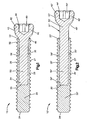
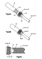
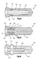
- the dynamic bone fixation element 10 of a first preferred embodiment includes a first bone engaging component 20 such as, for example, an externally threaded bone screw for engaging a patient's bone B, and a second load carrier engaging component 40 such as, for example, an enlarged head portion 42.
- the externally threaded bone screw includes an inner lumen 28 for receiving a shaft portion 50 extending from the head portion 42 of the load carrier engaging component 40. That is, the bone engaging component 20 includes a proximal end 22, a distal end 24, an outer surface 26 and a lumen 28.
- the lumen 28 extends at least partially through the bone engaging component 20 from the proximal end 22 to an end 25 proximal of the distal end 24.
- the outer surface 26 of the bone engaging component 20 includes a plurality of threads 27 extending along a length thereof for engaging the fractured bone or bone fragments B.
- the angle and the shape of the threads 27 may be varied to meet specific anchoring needs, such as, for example, in osteoporotic bones.
- the distal end 24 of the bone engaging component 20 may be tapered to include a self-tapping or a self-drilling tip as would be understood by those skilled in the art.
- the load carrier engaging component 40 includes a shaft portion 50 having an outer surface 56, and the head portion 42.
- the shaft portion 50 extends longitudinally from a proximal end 52 to a distal end 54 and is sized and shaped to at least partially fit within the lumen 28 of the bone engaging component 20.
- the head portion 42 may protrude radially outward from the proximal end 52 of the shaft portion 50 with a radius greater than that of the outer surface 56 of the shaft portion 50.
- the entire shaft portion 50 may be received within the lumen 28 such that the distal end 46 of the head portion 42 abuts the proximal end 22 of the bone engaging component 20.
- the lumen 28' formed in the bone engaging component 20' may be shorter than a length of the shaft portion 50' extending from the head portion 42' of the load carrier engaging portion 40' such that only a portion of the shaft portion 50' fits within the lumen 28' while a neck portion 31' protrudes from the bone engaging component 20'.
- the neck portion 31' may flex permitting the head portion 42' to move relative to the distal portion 54' of the shaft portion 50' and/or relative to the bone engaging component 20'.
- the neck portion 31' of the dynamic bone fixation element 10' is preferably positioned between a bone facing surface 13 of the load carrier 12 and the patient's bone or bone fragments B such that the neck portion 31' may move and/or deform as necessary to accommodate micro-movement of the patient's bone or bone fragments B.
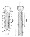
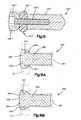
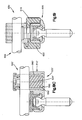
- the shaft portion 50" extending from the head portion 42" of the load carrier engaging component 40" has a diameter D S smaller than a diameter of the lumen D L formed in the bone engaging component 20" such that a gap (e.g., an annular space) exists between the outer surface 56" of the shaft portion 50" and an inner surface 30" of the lumen 28" so that the head portion 42" can move relative to the bone engaging component 20".
- a gap e.g., an annular space
- the dynamic bone fixation element 10" allows about two millimeters of movement of the head portion 42" away from a longitudinal axis 11" of the dynamic bone fixation element 10".
- the distal end 54" of the shaft portion 50" is preferably coupled and/or attached to the lumen 28" at end 25" such that the shaft portion 50" has greater freedom of movement within the lumen 28", as will be described in greater detail below. It will be understood by those of skill in the art that the size of the gap may be adjusted to adjust the amount of permitted movement between the bone engaging component 20" and the load carrier engaging component 40".
- the lumen 28" formed in the bone engaging component 20" may be tapered such that a diameter of the lumen 28" at the proximal end 22" of the bone engaging component 20" is larger than a diameter of the lumen 28" at end 25".
- the taper angle ⁇ of the lumen 28" may be between about zero to about ten degrees. It will be understood by those of skill in the art that the taper angle ⁇ may be adjusted to adjust the amount of permitted movement between the bone engaging component 20" and the load carrier engaging component 40".
- the size of the taper angle ⁇ may be used to limit the maximum amount of movement between the head portion 42" of the load carrier engaging component 40" and the bone engaging component 20" by limiting how far the shaft portion 50" may flex and/or move before the outer surface 56" of the shaft portion 50" contacts the inner surface 30" of the lumen 28" formed in the bone engaging component 20".
- the outer surface 56" of the shaft portion 50" may be tapered instead of or in addition to tapering the inner surface 30" of the lumen 28".
- the distal end 46" of the head portion 42" and the proximal end 22" of the bone engaging component 20" may be angled (angle ⁇ ) to provide increased clearance between the head portion 42" and the bone engaging component 20".
- the distal end 54" of the shaft 50" has a larger diameter than the proximal end 52" of the shaft 50" to accommodate the higher anticipated stresses that the distal end 54" of the shaft 50" is expected to experience.
- the outer surface 56" of the shaft 50" is preferably tapered so that the distal end 54" of the shaft 50" has a larger diameter than the proximal end 52" of the shaft 50".
- the lumen 28" formed in the bone engaging component 20" preferably includes one or more conically or “stepped” cylindrically shaped surfaces 29" to accommodate the increased motion of the shaft 50" with respect to the bone engaging component 20".
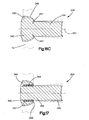
- the lumen 28" may also include a "trumpet”-shaped distal end and the shaft 50" may include a conical shape with an ellipsoid neck at the head portion and a lip 53" at the proximal end thereof for contacting the proximal end 22" of the bone engaging component 20".
- trauma-specific embodiments can include a shaft 50" that has a constant diameter for the entire length or most of the length of the shaft 50", which is easier to manufacture than a shaft 50" that gradually increases in diameter or has an increased diameter portion at the distal end 54" thereof.
- the lumen 28" may include a cylindrical shape and a trumpet-shaped distal end while the shaft 50" may include a cylindrical shape and an ellipsoid-shaped neck at the head portion.
- the shaft portion 50, 50', 50" may be integrally formed with the head portion 42, 42', 42".
- the shaft portion 50, 50', 50" may be coupled to the head portion 42, 42', 42" by any means now or hereafter known including but not limited to adhesive, welding, soldering, brazing, press-fit, friction fit, interference fit, a threaded connection, pinning, shrinking, engrailing, a cotter-pin, one or more fasteners such as via a pin or screw inserted longitudinally or radially, etc.
- the shaft portion 50, 50', 50" may be any size, shape and configuration including but not limited to straight, tapered, curved, solid, hollow, slotted, or formed as a spring like member such as, for example, a helical spring.
- the head portion 42, 42', 42" may also include a plurality of external threads 43, 43', 43" for engaging the load carrier 12 such that the dynamic bone fixation element 10, 10', 10" may be locked to the load carrier 12.
- the load carrier 12 includes a plurality of openings 14 through which the dynamic bone fixation elements 10, 10', 10" are inserted into the bone or bone fragments B and that the openings 14 may be threaded to engage the threading 43, 43', 43" formed on the head portion 42, 42', 42" of the load carrier engaging component 40, 40', 40".
- the head portion 42, 42', 42” preferably also includes a driving element 60, as will be described in greater detail below. It will also be understood by those of skill in the art that the head portion 42, 42', 42” may take any size and shape so long as the head portion 42, 42', 42" is structured to engage the load carrier 12 in a desired manner.
- the shaft portion 50, 50', 50" of the load carrier engaging component 40, 40', 40" may be integrally formed with the bone engaging component 20, 20', 20".
- the shaft portion 50, 50', 50" of the load carrier engaging component 40, 40', 40" may be coupled to the bone engaging component 20, 20', 20", preferably within the lumen 28, 28', 28", by any means now or hereafter known including but not limited to adhesive, welding, soldering, brazing, press-fit, friction fit, interference fit, a threaded connection, pinning, shrinking, engrailing, a cotter-pin, one or more fasteners such as via a pin or screw inserted longitudinally or radially, etc.
- the shaft portion 50, 50', 50" of the load carrier engaging component 40, 40', 40" is coupled to the bone engaging component 20, 20', 20" within the lumen 28, 28', 28" formed in the bone engaging component 20, 20', 20". That is, in a preferred embodiment, the shaft portion 50, 50', 50" is inserted into the lumen 28, 28', 28" and attached to the bone engaging component 20, 20', 20" at end 25, 25', 25", located distally of the proximal end 22, 22', 22" of the bone engaging component 20, 20', 20", and more preferably adjacent or proximate to the distal end 24, 24', 24" of the bone engaging component 20, 20', 20".
- the shaft portion 50, 50', 50" of the load carrier engaging component 40, 40', 40" is secured within the lumen 28, 28', 28" formed in the bone engaging component 20, 20', 20" by a press fit. That is, generally speaking, the diameter D L of the lumen 28, 28', 28" formed in the bone engaging component 20, 20', 20" is slightly smaller than the diameter D S of at least a portion of the shaft portion 50, 50', 50" (preferably the distal end 54, 54', 54" of the shaft portion 50, 50', 50") so that some amount of force is required to insert and remove the shaft portion 50, 50', 50" from the bone engaging component 20, 20', 20".
- the press fit engagement of the shaft portion 50, 50', 50" with the bone engaging component 20, 20', 20" ensures that the load carrier engaging component 40, 40', 40” will not separate from the bone engaging component 20, 20', 20” and enables transfer of longitudinal and torsional forces between the load carrier engaging component 40, 40', 40" and the bone engaging component 20, 20', 20".
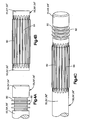
- the shaft portion 50, 50', 50" of the load carrier engaging component 40, 40', 40" may include one or more textured surfaces 80 formed thereon.
- the textured surfaces 80 are sized and configured, either in connection with the diameter D S of the shaft portion 50, 50', 50" or alone, to be slightly oversized as compared to the diameter D L of the lumen 28, 28', 28" formed in the bone engaging component 20, 20', 20".
- the textured surfaces 80 deform as the shaft portion 50, 50', 50" is being inserted into the lumen 28, 28', 28" formed in the bone engaging component 20, 20', 20". Thereafter, preferably due to material elasticity, the textured surface 80 returns to its original size thereby causing the textured surface 80 to press against the inner surface 30, 30', 30" of the lumen 28, 28', 28" to increase the resistance against the shaft portion 50, 50', 50" moving and/or separating from the bone engaging component 20, 20', 20".
- providing textured surfaces 80 on the outer surface 56, 56', 56" of the shaft portion 50, 50', 50” increases the contact pressure between the outer surface 56, 56', 56" of the shaft portion 50, 50', 50” and the inner surface 30, 30', 30" of the lumen 28, 28', 28” and thus increases the transferable forces and the contact strength between the shaft portion 50, 50', 50" and the bone engaging component 20, 20', 20".
- Fig. As best shown in Fig.
- the textured surface 80 may be in the form of a plurality of radially extending ridges or lamellas 82 formed on a portion of the shaft portion 50, 50', 50", preferably adjacent to the distal end 54, 54', 54" of the shaft portion 50, 50', 50".
- Providing radial ridges or lamellas 82 increases the axial or pull out strength of the shaft portion 50, 50', 50" with respect to the bone engaging component 20, 20', 20".
- the textured surface 80 may be in the form of a plurality of longitudinal extending ridges or lamellas 84 formed on a portion of the shaft portion 50, 50', 50", preferably adjacent to the distal end 54, 54', 54" of the shaft portion 50, 50', 50".
- Providing longitudinal ridges or lamellas 84 increases the torque or torsional strength of the shaft portion 50, 50', 50" with respect to the bone engaging component 20, 20', 20".
- the shaft portion 50, 50', 50" may include a plurality of radial ridges or lamellas 82 and a plurality of longitudinal ridges or lamellas 84 in order to increase both the axial and torsional strength of the shaft portion 50, 50', 50" with respect to the bone engaging component 20, 20', 20".
- the ridges or lamellas 82, 84 may have other shapes including, for example, spiral shaped.
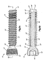
- the shaft portion 50, 50', 50" may be inserted into the lumen 28, 28', 28" formed in the bone contacting component 20, 20', 20" and welded W to the bone contacting component 20, 20', 20".
- the shaft portion 50, 50', 50" may be welded W to the bone contacting component 20, 20', 20" from the outside of the dynamic bone fixation element 10, 10', 10" by spiraling welding W between adjacent threads 27, 27', 27" formed on the outer surface 26, 26', 26" of the bone contacting component 20, 20', 20".
- the shaft portion 50, 50', 50" may be welded W to the bone contacting component 20, 20', 20" by any appropriate welding process now or hereafter known including but not limited to laser welding, electron beam welding, resistance stud welding, etc.
- the shaft portion 50, 50', 50" of the load carrier engaging component 40,40', 40" may be welded W to the bone engaging component 20, 20', 20" with or without the incorporation of a press-fit or some other means for coupling.
- the press-fit may be incorporated with or without the textured surfaces 80 (e.g., the radial and/or longitudinal ridges or lamellas 82, 84).
- the head portion 42, 42', 42" preferably also includes a driving element 60 for engaging a corresponding tip 62 formed on a drive tool 64, such as a screw driver for rotating the dynamic bone fixation element 10, 10', 10" into engagement with the patient's bone or bone fragments B.
- the driving element 60 may have any form now or hereafter known including, but not limited to, an external hexagon, a star drive pattern, a Phillips head pattern, a slot for a screw driver, a threading for a correspondingly threaded post, an internal recess, etc.
- the driving element 60 may be of any shape or structure so long as it permits the driving element 60 to drive the dynamic bone fixation element 10, 10', 10" into a desired location in the patient's bone or bone fragments B.
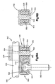
- the head portion 42, 42', 42" of the load carrier engaging component 40, 40', 40" includes a plurality of through holes 68 for receiving a plurality of pins 63 extending from a distal end of the drive tool 64 as best shown in Figs. 6A and 6B .
- the plurality of pins 63 being sized and configured to extend through the head portion 42, 42', 42" of the load carrier engaging component 40, 40', 40" and into contact with the bone engaging component 20, 20', 20" so that the plurality of pins 63 contact both the load carrier engaging component 40, 40', 40" and the bone engaging component 20, 20', 20" such that rotation of the drive tool 64 simultaneously rotates both the load carrier engaging component 40, 40', 40" and the bone engaging component 20, 20', 20".
- the head portion 42, 42', 42" of the load carrier engaging component 40, 40', 40" may include one or more projections 70 extending therefrom and the bone engaging component 20, 20', 20" may include one or more recesses 72 formed therein so that the projection 70 extends into the recess 72 so that rotation of the drive tool 64 simultaneously rotates both the load carrier engaging component 40,40', 40" and the bone engaging component 20, 20', 20".
- the recess 72 has a length larger than the length of the projection 70 so that some initial rotation of the head portion 42, 42', 42" is permitted prior to the projection 70 contacting the recess 72.
- the recess 72 may be formed on the head portion 42, 42', 42" and the projection 70 may be formed on the bone engaging component 20, 20', 20".
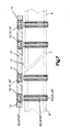
- the dynamic bone fixation element 10, 10', 10" may fix bones or bone fragments B of a broken bone to one another by coupling a load carrier 12 such as a plate to a patient's bone or bone fragments B via two or more dynamic bone fixation elements 10, 10', 10".
- the load carrier 12 may be a plate that is positioned along the bone B such that it extends across a fracture F separating the bone fragments B from one another.
- a dynamic bone fixation element 10, 10', 10" may be inserted into a first opening 14 formed in the plate 12 until the head portion 42, 42', 42" engages the first opening 14 and the bone engaging component 20, 20', 20" engages the first bone fragment B on one side of the bone fracture F.
- a second dynamic bone fixation element 10, 10', 10" may be inserted into a second opening 14 formed in the plate 12 in substantially the same manner as described above such that the second dynamic bone fixation element 10, 10', 10" engages the second bone fragment B.
- the dynamic bone fixation element 10, 10', 10" may be used to fix bone fragments B to one another. It will be understood by those of skill in the art that any number of dynamic bone fixation element 10, 10', 10" may be used to attach the load carrier 12 to the bone or bone fragments B.
- the human bone B is formed by a hard, thinner cortical outer portion surrounding a softer cancellous inner portion so that when view in cross-section, the human bone B includes a first layer of cortical bone, an intermediate layer of cancellous bone and a second layer of cortical bone.
- Rigid fixation generally includes the fixation of one or more bone screws on either side of a fracture F formed in the bone B.
- resulting stress on the fractured bone B causes bending of the bone B and plate 12 which, in turn, results in compression of the second layer of cortical bone (e.g., layer of cortical bone farthest from the plate 12).
- incorporation of dynamic bone fixation elements 10, 10', 10" enable parallel movement of the bone fragments B with respect to one another which in turn results in micro-movement of both layers of the cortical bone and hence facilitates the formation of callus in both the first and second layers of cortical bone.
- an exemplary procedure for internal long bone fixation involves using two or more dynamic bone fixation elements 10, 10', 10" on either side of a fracture F so that the resulting movement of the head portion 42, 42', 42" of the load carrier engaging component 40, 40', 40" with respect to the bone engaging component 20, 20', 20" enables, in addition to bending, parallel movement of the bone or bone fragments B across the fracture F.
- the preferred exemplary surgical procedure enables better healing across the fracture F as the bone/bone fragments B on either side of the first layer of cortical bone (e.g., layer of cortical bone nearest the plate 12) remain in constant contact which is contrary to prior art rigid fixation systems wherein the bone B is subjected to bending stress only. That is, when used in connection with an internal trauma application, when two or more dynamic bone fixation elements 10, 10', 10" are attached to a single bone or bone fragment B, the shaft portion 50, 50', 50" is forced to adopt a generally "S" shaped configuration generally parallel to one another to accommodate the micro-movements of the attached bone or bone fragment B.
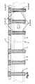
- a second exemplary surgical procedure as best shown in Fig. 10 may be carried out using two or more dynamic bone fixation elements 10, 10', 10" on one side of the fracture F while standard bone screws 5 may be used on the other side of the fracture F.
- Incorporation of standard bone screws 5 on one side of the fracture is particularly beneficial wherein, for one reason or another, the surgeon needs or desires to limit movement of the fractured bone to one side of the fracture only.
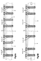
- a third exemplary surgical procedure as best shown in Figs. 11A and 11B involves using one or more standard bone screws 5 on one or both sides of the fracture F so that micro-movement of the bone/bone fragments B is prevented for some length of time. That is, for example, one or more standard bone screws 5 may be used on one or both sides of the fracture F so that for some initial period of time, for example, two or three weeks, micro-movement of the bone or bone fragments B is prevented so that the fracture site can be initially stabilized to facilitate initial callus formation. That is, days after initial fixation, tissue and/or cells may replicate and transform so that the cells on either side of the fracture develop until they unite with their counterparts from the other side of the fracture.
- the fracture F is bridged, restoring some of the bone's original strength. Thereafter, removal of the standard bone screws 5 from the surgical construct enables micro-movement of the bone/bone fragments B and/or enables distraction of the bone/bone fragments F. In addition, incorporation of one or more standard bone screws 5 may be used on one or both sides of the fracture F so that in cases of non-union, the bone or bone fragments B may be readjusted, repositioned, or alternative fixation may be applied.
- the dynamic bone fixation element 100 may be in the form of an integrally formed dynamic bone fixation element. That is, the load carrier engaging component 140 may be integrally formed with the bone engaging component 120 so that the shaft portion 150 may be integrally formed with the load carrier engaging component 140 and the bone engaging component 120.
- the dynamic bone fixation element 100 may achieve flexibility via the lumen 128 formed in the dynamic bone fixation element 100. That is, due to the size and configuration of the shaft portion 150 and the lumen 128 formed in the bone engaging component 120, the head portion 142 is able to flex and/or move with respect to the bone engaging component 120.
- the dynamic bone fixation element 100 may achieve flexibility via various designs of a neck portion 131 (e.g., area between the bone engaging component 120 and the load carrier engaging component 140).
- a neck portion 131 e.g., area between the bone engaging component 120 and the load carrier engaging component 140.
- material in the area of the neck 131 is removed in order to reduce structural stiffness.
- the dynamic bone fixation element 100 becomes increasingly more flexible.
- the dynamic bone fixation element 100 may be formed with one or more slots 190 in the neck portion 131. Slot(s) 190 may be formed in the neck portion 131 so that the neck 131 can function as a spring, allowing the neck portion 131 to flex, thereby allowing the head portion 142 to move with respect to the bone engaging component 120.
- the shape of the slot 190 formed in the neck portion 131 may be configured to take the form of any one of a plurality of shapes and profiles. Different profiles may be provided to control axial and rotational movement. For example, a helical spring profile allows axial movement but generally does not block screw rotation, whereas a rectangular profile allows axial movement and generally blocks screw rotation. Alternatively, a V-shaped spring profile blocks screw rotation and generally limits axial motion.
- the spring constant of the material and shape of the slots 190 formed in the neck portion 131 of the dynamic bone fixation element 100 may be used to control the movement of the head portion 142.
- additional element such as, for example, chamfers, conical openings, stiff pins, etc. may be incorporated as motion limitation means.
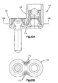
- the dynamic bone fixation element 100' may include a hollow volume 101' formed in and through the neck portion 131' such that a feather pin 150' may be located inside of the hollow volume 101'.
- the feather pin 150' is similar to the shaft portion previously described however the feather pin 150' may not be coupled to or engage both the bone engaging component 120' and the load carrier engaging component 140'.
- the feather pin 150' may be, for example, integrally formed with the bone engaging component 120'.
- the feather pin 150' may extend from the bone engaging component 120' through the hollow volume 101' of the neck portion 131' and into the head portion 142' of the load carrier component 140'.
- a gap 102' is preferably provided between the outer surface 156' of the feather pin 150' and the head portion 142'.
- the feather pin 150' preferably includes a head portion 151' and a body portion 153' with the head portion 151' having a larger diameter than the body portion 153'.
- the neck portion 131' of the dynamic bone fixation element 100' preferably includes a plurality of slots 190', as previously described in connection with dynamic bone fixation element 100. In use, the flexibility, both axial and compressive, is provided by the slots 190' formed in the neck portion 131' of the dynamic bone fixation element 100'.
- the flexibility may be limited by the size of the feather pin 150' and the gap 102' between the feather pin 150' and the head portion 142' of the dynamic bone fixation element 100' such that when the dynamic bone fixation element 100' is compressed, extended or moved axially, the feather pin 150' acts as a stop and limits the motion generally where, and when, the feather pin 150' contacts the interior walls of the head portion 142'.
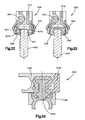
- the dynamic bone fixation element 100" may include a feather pin 150" that is not integrally formed with the dynamic bone fixation element 100" but rather coupled to a lumen 128" formed in the bone engaging component 120".
- the feather pin 150" may be coupled to the lumen 128" formed in the bone engaging component 120" by any means as previously described.
- the neck portion 131" of the dynamic bone fixation element 100" may be formed as a thin-walled hollow convex projection or bellow type structure which preferably functions as a spring to provide elasticity and/or flexibility.
- the hollow convex projection or bellow type structure may be further filled with a damper material to preferably control flexibility and protect the structural integrity of the dynamic bone fixation element 100".
- the feather pin 150" may be optional and may be removed from the dynamic bone fixation element 100".
- the dynamic bone fixation element 100"' may include a damper material or an elastic element 192"' in the neck portion 131"' ( e.g ., between the head portion 142"' and the bone engaging portion 120"') of the dynamic bone fixation element 100"'.
- a feather pin 150'" preferably extends through the damper material or elastic element 192"'.
- the damper material or elastic element 192"' may be fixed, axially moveable or rotatable with respect to the feather pin 150"'. In use, the damper material or elastic element 192"' acts as a damper.
- the feather pin 150', 150", 150"' may be sized and configured to be any number of shapes and sizes.
- the feather pin 150', 150", 150'" may include a head portion which may be cylindrical, conical, etc. , and the body portion may be longer or shorter and may be tapered.
- the lumen formed in the dynamic bone fixation element may be sized and configured to any number of different shapes and sizes, for example it may be cylindrical, or it may be tapered, etc .
- the ends of the feather pin 150', 150", 150"' are shown to be substantially circular, they may take on any geometric profile such as, for example, polygon.
- the dynamic bone fixation element 200 may include one or more slots 247 formed in the head portion 242 of the load carrier engaging component 240.
- the slots 247 may extend into the head portion 242 from a distal end 246 of the head portion 242 (as shown in Fig. 16A ).
- the slot 247 may extend into the head portion 242 from a proximal end 244 of the head portion 242 (as shown in Fig. 16B ).
- the slot 247 may extend from a circumferential edge 249 of the head portion 242 towards the longitudinal axis 201 of the dynamic bone fixation element 200 (as shown in Fig. 16C ).
- the slot 247 may be substantially parallel to the longitudinal axis 201 of the dynamic bone fixation element 200 or may be angled with respect to the longitudinal axis 201 of the dynamic bone fixation element 200. Alternatively and/or in addition, the slot 247 may be tapered, or alternatively the slot 247 may be straight or some other configuration. In use, the head portion 242 may flex, with the size, taper, and location of the slot 247 defining the range of flexibility. It should be appreciated that the slots 247 may be modified to fit a particular use of a dynamic bone fixation element 200, for example a slot 247 may have a larger or a smaller taper, it may extend less or farther into the head portion 242, it may be angled to any degree, and multiple slots 247 may be used.
- the dynamic bone fixation element 300 may include a multi-piece head assembly thereby preferably forming one or more slots 347 in the head portion 342.
- the multi-piece head assembly preferably includes a head portion 342, a body portion 350 and an optional damper material 394.
- the head portion 342 preferably includes an aperture 343 through which the body portion 350 is preferably inserted and to which it is preferably coupled.
- the head portion 342, aperture 343 and body portion 350 all being sized and configured so that one or more slots or gaps 347 are formed between the head portion 342 and the body portion 350.
- the one or more slots or gaps 347 are preferably filled with the damper material 394.
- any type of slot or gap 347 may be incorporated into the head portion 342, and any amount of damper material 394 may be used.
- the slot or gap 347 may be partially filled or completely filled with the damper material 394.
- coupling of the body portion 350 to the head portion 342 may be performed by any method including, but not limited to press fitting, a threaded connection, welding, pinning, shrinking, engrailing, etc.
- polymeric components or reduced structures such as flat springs, disk springs, meander shaped flat springs, etc . may also be incorporated.
- the dynamic bone fixation elements 10, 10', 10", 100, 100', 100", 100"', 200, 300 may be manufactured from any biocompatible material now or hereafter known in the art including but not limited to titanium, a titanium alloy, stainless steel, etc.
- the dynamic bone fixation elements 10-300 may be coated to facilitate osseo-integration.
- the bone engaging component 20, 20', 20", 120, 120', 120", 120"', 220, 320 may be coated, for example, with a hydroxylapatite, or its outer surface may be roughened, perforated or subjected to surface treatments such as, for example, anodic-plasma-chemical to embed hydroxylapatite into the titanium-oxide surface layer.
- the dynamic bone fixation elements 10-300 may be coated to enable one or more semi- or non- biocompatible materials to be used such as, for example, nickel, a nickel alloy, Ni-Ti-alloy (e.g., Nitinol), stainless steel, a memory shaped alloy, cobalt chromium (CoCr) or a cobalt chromium alloy such as, for example, CoCrMo, CoCrMoC, CoCrNi, CoCrWNi, etc.
- the bone engaging component 10-300 may be manufactured from cobalt chromium molybdenum and the outer threads may or may not be plasma coated with pure titanium.
- the bone engaging 20-320 and load carrier engaging component 40, 40', 40", 140, 140', 140", 140", 240, 340 may be manufactured from the same material.
- the bone engaging component 20-320 may be manufactured from a different material than the load carrier engaging component 40-340.
- the bone engaging component 20-320 may manufactured from a biocompatible metal, more preferably one that is easily processible so that, for example, the external bone thread may be milled such as, for example, titanium, a titanium alloy, such as TAV (Ti-6Al-4V) or TAN (Ti-6Al-7Ni).
- the load carrier engaging component 40-340 may be made from a high strength material (e.g., Rp 0.2>1,000 MPA) in order to provide high elasticity and maximum stability.
- the load carrier engaging component 40-340 is preferably manufactured from a material that provides resistance to fretting within the head-plate interface.
- the load carrier engaging component 40-340 may be made from, for example, a strong metal or metal alloy, such as CoCrMo, CoCrMoC, CoCrNi or CoCrWNi.
- the bone engaging component 20-320 is made from titanium or a titanium alloy such as, for example, TAV or TAN while the load carrier engaging portion 40-340 is made from cobalt chromium (CoCr).
- the damper materials used in some of the above exemplary embodiments may be any material now or hereafter known in the art with damping properties including, but not limited to polymers, silicone, urethane, polycarbonate-urethane (PCU), elastic members of the polyaryletherketone (PAEK) family, elastic members of polyesther-ether family, hydrogels, co-polymers, etc.
- the precise type and amount of damper material may be chosen based on the elasticity of the damping required.
- the dynamic bone fixation elements 10-300 may be formed so that they deform elastically when subjected to external forces as a result of micro-movement of the bone or bone fragments B to which they are coupled. Thus, if later micro-movements of the bone or bone fragments B are directed back toward an original position, the dynamic bone fixation elements will spring back to their original positions.
- the dynamic bone fixation elements 10-300 may be formed to plastically deform by the forces exerted during micro-movement of the bone or bone fragments B so that the dynamic bone fixation elements 10-300 retain their deformed shapes even after the forces imposed by the micro-movements have been removed.
- the dynamic bone fixation elements 10-300 may be formed to deform with a substantially uniform spring constant (e.g., a force twice as great produces twice the deformation). Alternatively, the dynamic bone fixation elements 10 -300 may be formed to remain substantially unflexed at all times until a force exerted by the micro-movements exceeds a predetermined limit.
- a substantially uniform spring constant e.g., a force twice as great produces twice the deformation.
- the shaft portion is preferably designed as a bendable pin so that the shaft portion is capable of moving with respect to the bone engaging component and able to give within a limited range.
- the ratio of the outer diameter of the bone engaging component to displacement is between about 10 to about 20, and more preferably about 15.
- the ratio of the outer diameter of the bone engaging component to the outer diameter of the shaft portion is between about 1.4 to about 2.2, more preferably 1.8.
- the ratio of the outer diameter of the bone engaging component to the effective flexible length of the shaft portion is between about 3.5 to about 5.5, more preferably 4.6.
- Exemplary sizes for the bone engaging component and load carrier engaging component are illustrated in Table 1.
- fixation clamps are often used when bony structures, such as facet joints or osteophites, would prevent a straightforward fixation of a rod into a pedicle screw. As a result, fixation clamps may be used to bridge around such hurdles. In these cases it may be advantageous to provide elasticity in the fixation clamps through, for example, the incorporation of a damper.
- the damper may be in the form of an elastic or polymeric component such as PCU, silicone, rubber, etc.
- the damper may be in the form of a spring such as flat springs, disk springs, meander shaped flat springs, etc .
- the dynamic pedicle screw fixation clamp 500 may include a bone screw 502 and a frame 510.
- the frame 510 preferably includes a pedicle screw clamping assembly 520 and a rod clamping assembly 530.
- the pedicle screw clamping assembly 520 preferably includes a clamping sleeve 522, a collet 524, and a locking mechanism 526 to secure and/or lock the position of the bone screw 502 with respect to the frame 510, although other configurations for the pedicle screw clamping assembly 520 are contemplated.
- the rod clamping assembly 530 may be offset or located to the side of the pedicle screw clamping assembly 520.
- the rod clamping assembly 530 preferably includes a recess 532, a clamp portion 534, a locking cap portion 536 and a damper 550.
- the clamp portion 534 is preferably shaped like a pedestal and includes a rod-receiving portion 542 attached to a column portion 540.
- the rod-receiving portion 542 preferably has a perimeter larger than the circumference of the column portion 540. Additionally, the rod-receiving portion 542 preferably has a length or perimeter that is slightly larger than the diameter of the recess 532 formed in the frame 510.
- the column portion 540 is preferably sized and configured to be inserted into the recess 532 formed in the frame 510 so that there is a clearance or gap between the outer surface of the column portion 540 and the inner surface of the recess 532. Additionally, the column portion 540 preferably has a height that is slightly larger than the height of the recess 532 formed in the frame 510 so that there is a clearance or gap between the bottom surface of the rod-receiving portion 542 and the top surface of the frame 510.
- the gap between the outer surface of the column portion 540 and the inner surface of the recess 532 and the gap between the bottom surface of the rod-receiving portion 542 and the top surface of the frame 510 is filled with the damper 550, more preferably a damper material.
- the damper 550 is preferably annularly shaped and inserted into the recess 532 formed in the frame 510.
- the column portion 540 is preferably inserted into the recess 532 and through a hollow cavity formed in the damper 550 so that the column portion 540 is surrounded by the damper 550.
- the frame 510 may also include an aperture 545 formed in the bottom surface thereof in communication with the recess 532, the aperture 545 being sized and configured to receive an end 542 of the column portion 540. Preferably there is a clearance or gap between the end 542 of the column portion 540 and the inner circumference of the aperture 545.
- the damper material 550 preferably is press-fitted or injection molded into the recess 532 formed in the frame 510.
- the damper 550 may be press-fitted or injection molded into another frame (not shown), which in turn would be press-fitted into the recess 532 formed in the frame 510.
- a rod 504 is preferably placed into the rod-receiving portion 542 and clamped therein by the locking cap 536. In this position, the rod 504 is free to move with respect to the frame 510 and with respect to the pedicle screw 502 due to the flexibility of the damper 550.
- the clamp portion 534 is sized and configured to contact the frame 510 once the dynamic pedicle screw fixation clamp 500 has reached a maximum angle of desired flex.
- the clamping portion 534' may have a rod receiving portion 542' and an extension portion 560'
- the extension portion 560' may be a hollow cylindrical element that includes a plurality of slots forming flexible tabs 562'.
- the flexible tabs 562' are inserted into the recess 532' formed in the frame 510'.
- the interior volume of the flexible tabs 562' is preferably filled with the damper 550'.
- the slots provide additional flexibility to the clamping portion 534' so that the bottom portion of the clamping portion 534' along with the damper 550' permits movement of the rod 502' due to the flexibility of the damper 550' and the resulting flexing of the tabs 562'.
- the rod-clamping portion 542' may be rotatable within the recess 532' formed in the frame 510'.
- the dynamic pedicle screw fixation clamp 600 may include a pedicle screw clamping assembly 620 and a rod clamping assembly 630 wherein the pedicle screw clamping assembly 620 and the rod clamping assembly 630 are in vertical alignment, as opposed to the side-by-side configuration of the first preferred embodiment.
- a damper 650 is preferably located in between the pedicle screw clamping assembly 620 and the rod clamping assembly 630 so that flexibility is provided between the pedicle screw clamping assembly 620 and the rod clamping assembly 630.
- the damper 650 may interconnect the pedicle screw clamping assembly 620 and the rod clamping assembly 630.
- the damper 650 may be fixed between the pedicle screw clamping assembly 620 and the rod clamping assembly 630 by any mechanism including, for example, via a frame, a ring, etc.
- the damper 650 is injection molded into and around the frame or ring 610 to connect the pedicle screw clamping assembly 620 and the rod clamping assembly 630 together (as shown in the left side of Fig. 19 ).
- the dynamic pedicle screw fixation clamp 700 may include a pedicle screw clamping assembly 720 and a rod clamping assembly 730.
- the rod clamping assembly 730 may be offset or located to the side of the pedicle screw clamping assembly 720 via a frame 710.
- the slots 712 may take any shape or form as needed for the amount of flexibility that is desired.
- the dynamic pedicle screw fixation clamp 800 may include a pedicle screw clamping assembly 820 and a rod clamping assembly 830.
- the rod clamping assembly 830 may be offset or located to the side of the pedicle screw clamping assembly 820 via a connecting member 810.
- the connecting member 810 preferably includes a dynamic section 840.
- the dynamic section 840 may be in the form of a spring (as shown in Figs. 21A and 21 B ), a damper material, etc .
- the dynamic section 840 of connecting member 810 allows flexing of the rod clamp assembly 830 with respect to the screw clamp assembly 820.
- the dynamic section 840 may be sized and configured to provide the level of flexibility that is desired for a particular application.
- the connecting member 810 may be coupled to the pedicle screw clamping assembly 820 and to the rod clamping assembly 830 by an mechanism know.
- the connecting member 810 may be coupled to the body of the screw clamp assembly 820 and may be received within a connector clamp 832 located in the rod clamping assembly 830.
- the dynamic pedicle screw fixation clamp 900 may include a rod/screw clamping assembly 910, a locking ring 920 and a dynamic bone screw 902.
- the screw/rod clamping assembly 910 may be a side opening pedicle screw assembly.
- the dynamic bone screw 902 and the rod 904 are preferably inserted into their respective receiving portions in the rod/screw clamping assembly 910.
- tightening of the rod 904 within the rod receiving portion causes the rod 904 to press down onto the locking ring 920, which in turns causes the screw receiving portion of rod/screw clamping assembly 910 to tighten and clamp the dynamic bone screw 902.
- the dynamic bone screw 902 however preferably incorporates one or more flexible elements so that the bone screw 902 can move or flex with respect to the rod 904.
- the dynamic screw 902 may include a head portion 906 that includes a cavity for receiving a pair of beveled spring washers 907.
- the first beveled spring washer 907a preferably is located on the rod-facing end of the dynamic screw 902 with its center angled towards the second beveled spring washer 907b, whereas the second beveled spring washer 907b preferably is located adjacent to the shaft of the dynamic screw 902 with its center angled towards the first beveled spring washer 907a.
- the dynamic screw 902 preferably also includes a ridge 903 formed thereon, the ridge 903 being received between the two beveled spring washers 907.
- the ridge 903 is preferably sized and configured to keep the beveled springs washers 907 from slipping.
- the beveled spring washers 907 flex, allowing the bone contacting portion to deflect and flex relative to the head portion 906, and hence relative to the remainder of the pedicle screw assembly 900.
- the bone screw 902 may be received by the head portion 906 and/or attached to the springs in any number of ways including, but not limited to, welding, gluing, etc.
- the structure of the screw may be modified.
- the screw may be configured not to have a ridge, or to include recesses or grooves to receive the springs, etc.
- the springs of the screw head design may be replaced with a damper material 950, or alternatively the springs in Fig. 22 can be used with a damper material 950.
- the dynamic pedicle screw fixation clamp 1000 may include a pedicle screw clamping assembly 1020, a rod clamping assembly 1030 and a flexible element 1040 wherein the flexible element 1040 is located between the rod clamping assembly 1030 and the pedicle screw clamping assembly 1020.
- the rod clamping assembly 1030 may be in the form of a side opening rod clamping assembly.
- the pedicle screw clamping assembly 1020 is preferably surrounded by a locking ring 1022.
- the flexible element 1040 connecting the pedicle screw clamping assembly 1020 and the rod clamping assembly 1030 is preferably made of a damper material.
- the damper material 1040 flexes, compresses and stretches to allow the pedicle screw clamping assembly 1020 to move with respect to the rod clamping assembly 1030.
- a damper material element is described, the use of mechanical springs is also possible.
Description
- Millions of people suffer from bone fractures each year. Treatment of this condition is frequently accomplished by rigid fixation which involves the use of implants such as, for example, longitudinal load carriers (e.g., bone plates, rods, etc.) fixed to a patient's bone or bone fragments via a plurality of bone fixation elements (e.g., bone screws, hooks, pins, rivets, etc.) in order to stabilize the fractured bone across the fracture.
- The use of flexible or dynamic fixation in bone fixation is believed to provide advantages by reducing the amount of stress generally associated with rigid fixation, and thus better protect the patient's bone or bone fragments.
- From
US-A 2006/074421 BICKLEY ET AL. a fixation augmentation device is known which comprises first component which engages a bone plate and which is affixed to a bone by means of expandable flanges and a second component which is screwed into the first component until the flanges are expanded in a hole in the bone. - The present invention relates generally to surgical devices to stabilize bones or bone fragments. More specifically, the present invention relates to a dynamic bone fixation element, to stabilize a bone or bone fragments using the same.
- In one exemplary embodiment of the present invention, the dynamic bone fixation element includes a bone engaging component and a load carrier engaging component. The bone engaging component includes a proximal end, a distal end, and a lumen extending at least partially from the proximal end of the bone engaging component. The lumen defines an inner surface. The load carrier engaging component includes a head portion for engaging a load carrier and a shaft portion extending from the head portion. The shaft portion includes a proximal end, a distal end and an outer surface. The shaft portion is sized and configured to at least partially extend into the lumen formed in the bone engaging component. At least a portion of the shaft portion has a diameter DS and at least a portion of the lumen has a diameter DL, the diameter DL being greater than the diameter DS so that at least a portion of the outer surface of the shaft portion is spaced away from at least a portion of the inner surface of the lumen. In addition, the distal end of the shaft portion is coupled to the lumen at a position distally of the proximal end of the bone engaging component so that the head portion moves with respect to the bone engaging component and hence the engaged bone or bone fragments may move with respect to the load carrier to enable micro-movement.
- The inner surface of the lumen may be tapered at an angle θ such that the diameter DL of the lumen at a proximal end thereof is larger than the diameter DL of the lumen at a position distally of the proximal end. The taper angle θ of the lumen is preferably between about zero degrees to about ten degrees.
- The shaft portion is preferably integrally formed with the head portion. The shaft portion is preferably coupled to the bone engaging component within the lumen at a position proximate to the distal end of the bone engaging component. The shaft portion is preferably coupled to the bone engaging component within the lumen via a press fit connection. The distal end of the shaft portion preferably has a diameter greater than the diameter DL of the lumen.
- Alternatively and/or in addition, the shaft portion may include one or more textured surfaces formed thereon. The textured surfaces are preferably elastically deformable so that the textured surfaces deform as the shaft portion is being inserted into the lumen. Thereafter the textured surfaces preferably return to their larger original size so that the textured surface press against the inner surface of the lumen to increase a contact pressure between the outer surface of the shaft portion and the inner surface of the lumen. The textured surface may be in the form of a plurality of radially extending ridges formed on a portion of the shaft portion. Alternatively and/or in addition, the textured surface may be in the form of a plurality of longitudinal extending ridges formed on a portion of the shaft portion.
- In addition, the outer surface of the bone engaging component preferably includes a plurality of threads formed on the outer surface thereof for engaging the patient's bone or bone fragments, the outer surface of the shaft portion may be welded to the inner surface of the lumen by welding in-between adjacent threads formed on the outer surface of the bone engaging component.
- The head portion preferably includes a driving element for engaging a tip formed on a drive tool. For example, the head portion may include a plurality of through holes for receiving a plurality of pins formed on the tip of the drive tool, the pins being sized and configured to extend through the head portion of the load carrier engaging component and into contact with the bone engaging component so that the plurality of pins contact both the load carrier engaging component and the bone engaging component such that rotation of the drive tool simultaneously rotates both the load carrier engaging component and the bone engaging component. Alternatively, for example, the head portion may include one or more projections extending therefrom and the bone engaging component includes one or more recesses formed therein so that the projection extends into the recess so that rotation of the drive tool simultaneously rotates both the load carrier engaging component and the bone engaging component.
- A method for internally fixing a load carrier across a fracture in a bone includes the steps of (a) providing a plurality of dynamic bone fixation elements; (b) making an incision; and (c) coupling the load carrier to the patient's bone via two or more dynamic bone fixation elements on either side of the fracture so that the dynamic bone fixation elements enable parallel movement of the bone or bone fragments across the fracture; and (d) closing the incision so that the load carrier and plurality of dynamic bone fixation elements remain within the patient. Preferably the dynamic bone fixation elements each include a bone engaging component for engaging the bone and a load carrier engaging component for engaging the load carrier, the bone engaging component being moveably associated with the load carrier engaging component so that movement of the load carrier engaging component with respect to the bone engaging component enables the parallel movement of the bone or bone fragments across the fracture. The bone engaging component preferably includes a lumen extending at least partially from a proximal end of the bone engaging component, the lumen defining an inner surface. The load carrier engaging component preferably includes a head portion for engaging the load carrier and a shaft portion extending from the head portion, the shaft portion having a proximal end, a distal end and an outer surface, the shaft portion being sized and configured to at least partially extend into the lumen formed in the bone engaging component. Preferably, at least a portion of the outer surface of the shaft portion is spaced away from at least a portion of the inner surface of the lumen so that the head portion moves with respect to the bone engaging component.
- The method for fixing the load carrier across the fracture in the bone may also include inserting one or more standard bone screws on one or both sides of the fracture F so that micro-movement of the bone is prevented for an initial period of time so that thereafter the standard bone screws may be removed from the patient's bone after the initial period of time has lapsed so that micro-movement of the bone is enabled.
- The foregoing summary, as well as the following detailed description of the preferred embodiments of the application, will be better understood when read in conjunction with the appended drawings. For the purposes of illustrating the preferred dynamic bone fixation elements of the present application, there is shown in the drawings preferred embodiments. It should be understood, however, that the application is not limited to the precise arrangements and instrumentalities shown. In the drawings:
-
Fig. 1 shows a cross-sectional view of a dynamic bone fixation element according to a first exemplary embodiment of the present invention; -
Fig. 2 shows a cross-sectional view of a dynamic bone fixation element according to a second exemplary embodiment of the present invention; -
Fig. 3 shows a cross-sectional view of a dynamic bone fixation element according to a third exemplary embodiment of the present invention; -
Fig. 3A shows a cross-sectional view of an alternate embodiment of the dynamic bone fixation element shown inFig. 3 , the cross-sectional view illustrating preferred, exemplary dimensions of the dynamic bone fixation element; -
Fig. 3B shows a cross-sectional view of an alternate embodiment of the dynamic bone fixation element shown inFig. 3 , the cross-sectional view illustrating an exemplary dynamic bone fixation element for use in spinal procedures; -
Fig. 3C shows a cross-sectional view of an alternate embodiment of the dynamic bone fixation element shown inFig. 3 , the cross-sectional view illustrating an exemplary dynamic bone fixation element for use in trauma procedures; -
Fig. 4A shows a detailed view of a plurality of radially extending ridges or lamellas formed on a distal end of a shaft portion of a load carrier engaging component in accordance with one exemplary embodiment of the load carrier engaging component; -
Fig. 4B shows a detailed view of a plurality of longitudinally extending ridges or lamellas formed on a distal end of a shaft portion of a load carrier engaging component in accordance with one exemplary embodiment of the load carrier engaging component; -
Fig. 4C shows a detailed view of a plurality of radially extending ridges or lamellas and a plurality of longitudinally extending ridges or lamellas formed on a distal end of a shaft portion of a load carrier engaging component in accordance with one exemplary embodiment of the load carrier engaging component; -
Fig. 5A shows a side view of an exemplary method for coupling a shaft portion of a load carrier engaging component to a bone engaging component; -
Fig. 5B shows a cross sectional view of the exemplary method for coupling the shaft portion of the load carrier engaging component to the bone engaging component taken alongline 5B-5B shown inFig. 5A ; -
Fig. 6A shows an exploded, perspective view of a drive element for coupling a head portion of a dynamic bone fixation element to a drive tool in accordance with a first preferred embodiment of the present invention; -
Fig. 6B shows a side view of the drive element coupled to the head portion of the drive tool shown inFig. 6A ; -
Fig. 6C shows a side view of a drive element for coupling a head portion of a dynamic bone fixation element to a drive tool in accordance with a second preferred embodiment of the present invention; -
Fig. 7 shows a cross section view of the dynamic bone fixation elements interconnecting a load carrier to a patient's bone; -
Fig. 8 shows a cross-sectional view of an exemplary method for long bone fixation; -
Fig. 9 shows a second cross-sectional view of the exemplary method for long bone fixation shown inFig. 8 ; -
Fig. 10 shows a cross-sectional view of an exemplary method for long bone fixation; -
Fig. 11A shows a cross-sectional view of an exemplary method for long bone fixation; -
Fig. 11B shows a second cross-sectional view of the exemplary method for long bone fixation shown inFig. 11A ; -
Fig. 12 shows a cross-sectional view of a dynamic bone fixation element not according to the invention; -
Fig. 13 shows a cross-sectional view of a dynamic bone fixation element not according to the invention; -
Fig. 14 shows a cross-sectional view of a dynamic bone fixation element not according to the invention; -
Fig. 15 shows a cross-sectional view of a dynamic bone fixation element not according to the invention; -
Fig. 16A shows a first detailed, cross-sectional view of a head portion of a dynamic bone fixation element not according to the invention; -
Fig. 16B shows a second detailed, cross-sectional view of a head portion of a dynamic bone fixation element not according to the invention; -
Fig. 16C shows a third detailed, cross-sectional view of a head portion of a dynamic bone fixation element not according to the invention; -
Fig. 17 shows a partial cross-sectional view of a dynamic bone fixation element not according to the invention; -
Fig. 18A shows a cross-sectional view of a dynamic pedicle screw fixation clamp not according to the invention; -
Fig. 18B shows a detailed, cross-sectional view of a portion of the dynamic pedicle screw fixation clamp shown inFig. 18A ; -
Fig. 18C shows a cross-sectional view of an alternate embodiment of the dynamic pedicle screw fixation clamp shown inFig. 18A ; -
Fig. 19 shows a cross-sectional view of a dynamic pedicle screw fixation clamp not according to the invention; -
Fig. 20A shows a cross-sectional view of a dynamic pedicle screw fixation clamp not according to the invention; -
Fig. 20B shows a cross-sectional view of the frame used in connection with the dynamic pedicle screw fixation clamp shown inFig. 20A taken alongline 20B-20B ofFig. 20A ; -
Fig. 21A shows a cross-sectional view of a dynamic pedicle screw fixation clamp not according to the invention; -
Fig. 21B shows a detailed, cross-sectional view of the dynamic section of the connecting member used in connection with the dynamic pedicle screw fixation clamp shown inFig. 21A ; -
Fig. 22 shows a cross-sectional view of a dynamic pedicle screw fixation clamp not according to the invention; -
Fig. 23 shows a cross-sectional view of another dynamic pedicle screw fixation clamp different from the one shown inFig. 22 ; and -
Fig. 24 shows a cross-sectional view of a dynamic pedicle screw fixation clamp not according to the invention. - Certain terminology is used in the following description for convenience only and is not limiting. The words "right", "left", "top" and "bottom" designate directions in the drawings to which reference is made. The words "inwardly" and "outwardly" refer to directions toward and away from, respectively, the geometric center of the device and designated parts thereof. The words, "anterior", "posterior", "superior", "inferior" and related words and/or phrases designate preferred positions and orientations in the human body to which reference is made and are not meant to be limiting. The terminology includes the above-listed words, derivatives thereof and words of similar import.
- Certain exemplary embodiments of the invention will now be described with reference to the drawings. In general, the present invention relates to a dynamic
bone fixation element bone fixation element bone fixation elements bone fixation elements bone fixation elements - Generally speaking, as will be described in greater detail below, a dynamic
bone fixation element bone engaging component carrier engaging component enlarged head portion carrier engaging component bone engaging component bone fixation element carrier engaging component bone engaging component load carrier 12. That is, as will be described in greater detail below, the loadcarrier engaging component head portion bone plate 12 or rod, and ashaft portion bone engaging component external threads inner lumen shaft portion outer surface shaft portion inner surface lumen head portion carrier engaging component bone engaging component distal end head portion proximal end bone engaging component shaft portion carrier engaging component lumen bone engaging component bone fixation element load carrier 12. - Referring to
Figure 1 , the dynamicbone fixation element 10 of a first preferred embodiment includes a firstbone engaging component 20 such as, for example, an externally threaded bone screw for engaging a patient's bone B, and a second loadcarrier engaging component 40 such as, for example, anenlarged head portion 42. The externally threaded bone screw includes aninner lumen 28 for receiving ashaft portion 50 extending from thehead portion 42 of the loadcarrier engaging component 40. That is, thebone engaging component 20 includes aproximal end 22, adistal end 24, anouter surface 26 and alumen 28. Thelumen 28 extends at least partially through thebone engaging component 20 from theproximal end 22 to anend 25 proximal of thedistal end 24. - In a preferred embodiment, the
outer surface 26 of thebone engaging component 20 includes a plurality ofthreads 27 extending along a length thereof for engaging the fractured bone or bone fragments B. The angle and the shape of thethreads 27 may be varied to meet specific anchoring needs, such as, for example, in osteoporotic bones. Thedistal end 24 of thebone engaging component 20 may be tapered to include a self-tapping or a self-drilling tip as would be understood by those skilled in the art. - The load
carrier engaging component 40 includes ashaft portion 50 having anouter surface 56, and thehead portion 42. Theshaft portion 50 extends longitudinally from aproximal end 52 to adistal end 54 and is sized and shaped to at least partially fit within thelumen 28 of thebone engaging component 20. As shown, thehead portion 42 may protrude radially outward from theproximal end 52 of theshaft portion 50 with a radius greater than that of theouter surface 56 of theshaft portion 50. Theentire shaft portion 50 may be received within thelumen 28 such that thedistal end 46 of thehead portion 42 abuts theproximal end 22 of thebone engaging component 20. - Alternatively, referring to a second embodiment of the dynamic
bone fixation element 10' as best shown inFig. 2 , the lumen 28' formed in the bone engaging component 20' may be shorter than a length of the shaft portion 50' extending from the head portion 42' of the load carrier engaging portion 40' such that only a portion of the shaft portion 50' fits within the lumen 28' while a neck portion 31' protrudes from the bone engaging component 20'. The neck portion 31' may flex permitting the head portion 42' to move relative to the distal portion 54' of the shaft portion 50' and/or relative to the bone engaging component 20'. In use, the neck portion 31' of the dynamicbone fixation element 10' is preferably positioned between abone facing surface 13 of theload carrier 12 and the patient's bone or bone fragments B such that the neck portion 31' may move and/or deform as necessary to accommodate micro-movement of the patient's bone or bone fragments B. - Preferably, referring to a third preferred embodiment of the dynamic
bone fixation element 10" as best shown inFigs. 3-3C , theshaft portion 50" extending from thehead portion 42" of the loadcarrier engaging component 40" has a diameter DS smaller than a diameter of the lumen DL formed in thebone engaging component 20" such that a gap (e.g., an annular space) exists between theouter surface 56" of theshaft portion 50" and aninner surface 30" of thelumen 28" so that thehead portion 42" can move relative to thebone engaging component 20". Preferably the dynamicbone fixation element 10" allows about two millimeters of movement of thehead portion 42" away from alongitudinal axis 11" of the dynamicbone fixation element 10". In other embodiments more or less flexing of theshaft portion 50" and more or less movement of thehead portion 42" is possible. Thedistal end 54" of theshaft portion 50" is preferably coupled and/or attached to thelumen 28" atend 25" such that theshaft portion 50" has greater freedom of movement within thelumen 28", as will be described in greater detail below. It will be understood by those of skill in the art that the size of the gap may be adjusted to adjust the amount of permitted movement between thebone engaging component 20" and the loadcarrier engaging component 40". - In addition and/or alternatively, the
lumen 28" formed in thebone engaging component 20" may be tapered such that a diameter of thelumen 28" at theproximal end 22" of thebone engaging component 20" is larger than a diameter of thelumen 28" atend 25". The taper angle θ of thelumen 28" may be between about zero to about ten degrees. It will be understood by those of skill in the art that the taper angle θ may be adjusted to adjust the amount of permitted movement between thebone engaging component 20" and the loadcarrier engaging component 40". In use, the size of the taper angle θ may be used to limit the maximum amount of movement between thehead portion 42" of the loadcarrier engaging component 40" and thebone engaging component 20" by limiting how far theshaft portion 50" may flex and/or move before theouter surface 56" of theshaft portion 50" contacts theinner surface 30" of thelumen 28" formed in thebone engaging component 20". It should be noted that theouter surface 56" of theshaft portion 50" may be tapered instead of or in addition to tapering theinner surface 30" of thelumen 28". Alternatively and/or in addition, thedistal end 46" of thehead portion 42" and theproximal end 22" of thebone engaging component 20" may be angled (angle α) to provide increased clearance between thehead portion 42" and thebone engaging component 20". - With particular reference to
Figs. 3B and 3C , to satisfy the different loads anticipated in spine and trauma procedures, generally speaking, for spinal applications (as best shown inFig. 3B ), preferably thedistal end 54" of theshaft 50" has a larger diameter than theproximal end 52" of theshaft 50" to accommodate the higher anticipated stresses that thedistal end 54" of theshaft 50" is expected to experience. Thus, for spine specific embodiments where straight bending as opposed to S-bending is expected, theouter surface 56" of theshaft 50" is preferably tapered so that thedistal end 54" of theshaft 50" has a larger diameter than theproximal end 52" of theshaft 50". In addition, thelumen 28" formed in thebone engaging component 20" preferably includes one or more conically or "stepped" cylindrically shapedsurfaces 29" to accommodate the increased motion of theshaft 50" with respect to thebone engaging component 20". As shown, thelumen 28" may also include a "trumpet"-shaped distal end and theshaft 50" may include a conical shape with an ellipsoid neck at the head portion and alip 53" at the proximal end thereof for contacting theproximal end 22" of thebone engaging component 20". - This is in contrast to trauma applications (as best shown in
Fig. 3C ) such as, long bone fixation, where it is generally not necessary to increase the diameter of thedistal end 54" of theshaft 50" since theshaft 50" generally undergoes S-bending (something it won't do in spine applications) and hence, in trauma applications, the distal and proximal ends 52", 54" of theshaft 50" experience approximately the same amount of force. Thus, preferably trauma-specific embodiments can include ashaft 50" that has a constant diameter for the entire length or most of the length of theshaft 50", which is easier to manufacture than ashaft 50" that gradually increases in diameter or has an increased diameter portion at thedistal end 54" thereof. As shown, for trauma specific embodiments where S-bending is expected, thelumen 28" may include a cylindrical shape and a trumpet-shaped distal end while theshaft 50" may include a cylindrical shape and an ellipsoid-shaped neck at the head portion. - The
shaft portion head portion shaft portion head portion shaft portion - The
head portion external threads load carrier 12 such that the dynamicbone fixation element load carrier 12. It will be understood by those of skill in the art that theload carrier 12 includes a plurality ofopenings 14 through which the dynamicbone fixation elements openings 14 may be threaded to engage the threading 43, 43', 43" formed on thehead portion carrier engaging component head portion element 60, as will be described in greater detail below. It will also be understood by those of skill in the art that thehead portion head portion load carrier 12 in a desired manner. - The
shaft portion carrier engaging component bone engaging component shaft portion carrier engaging component bone engaging component lumen - Preferably, the
shaft portion carrier engaging component bone engaging component lumen bone engaging component shaft portion lumen bone engaging component end proximal end bone engaging component distal end bone engaging component shaft portion carrier engaging component lumen bone engaging component lumen bone engaging component shaft portion distal end shaft portion shaft portion bone engaging component shaft portion bone engaging component carrier engaging component bone engaging component carrier engaging component bone engaging component - Referring to
Figs. 4A-4C , in order to increase the coupled strength between the loadcarrier engaging component bone engaging component shaft portion carrier engaging component textured surfaces 80 formed thereon. In use, thetextured surfaces 80 are sized and configured, either in connection with the diameter DS of theshaft portion lumen bone engaging component textured surfaces 80 deform as theshaft portion lumen bone engaging component textured surface 80 returns to its original size thereby causing thetextured surface 80 to press against theinner surface lumen shaft portion bone engaging component textured surfaces 80 on theouter surface shaft portion outer surface shaft portion inner surface lumen shaft portion bone engaging component Fig. 4A , thetextured surface 80 may be in the form of a plurality of radially extending ridges orlamellas 82 formed on a portion of theshaft portion distal end shaft portion lamellas 82 increases the axial or pull out strength of theshaft portion bone engaging component Fig. 4B , thetextured surface 80 may be in the form of a plurality of longitudinal extending ridges orlamellas 84 formed on a portion of theshaft portion distal end shaft portion lamellas 84 increases the torque or torsional strength of theshaft portion bone engaging component Fig. 4C , theshaft portion lamellas 84 in order to increase both the axial and torsional strength of theshaft portion bone engaging component lamellas - Alternatively and/or in addition, as best shown in
Figs. 5A and 5B , theshaft portion lumen bone contacting component bone contacting component shaft portion bone contacting component bone fixation element adjacent threads outer surface bone contacting component threads bone engaging component shaft portion bone contacting component shaft portion carrier engaging component bone engaging component lamellas 82, 84). - As previously mentioned, the
head portion element 60 for engaging acorresponding tip 62 formed on adrive tool 64, such as a screw driver for rotating the dynamicbone fixation element element 60 may have any form now or hereafter known including, but not limited to, an external hexagon, a star drive pattern, a Phillips head pattern, a slot for a screw driver, a threading for a correspondingly threaded post, an internal recess, etc. It will also be understood by those of skill in the art that the drivingelement 60 may be of any shape or structure so long as it permits the drivingelement 60 to drive the dynamicbone fixation element - Preferably, in order to engage the
head portion carrier engaging component bone engaging component carrier engaging component bone engaging component head portion carrier engaging component holes 68 for receiving a plurality of pins 63 extending from a distal end of thedrive tool 64 as best shown inFigs. 6A and 6B . The plurality of pins 63 being sized and configured to extend through thehead portion carrier engaging component bone engaging component carrier engaging component bone engaging component drive tool 64 simultaneously rotates both the loadcarrier engaging component bone engaging component - Alternatively, as best shown in
Fig. 6C , thehead portion carrier engaging component more projections 70 extending therefrom and thebone engaging component more recesses 72 formed therein so that theprojection 70 extends into therecess 72 so that rotation of thedrive tool 64 simultaneously rotates both the loadcarrier engaging component bone engaging component recess 72 has a length larger than the length of theprojection 70 so that some initial rotation of thehead portion projection 70 contacting therecess 72. As will be appreciated by one of ordinary skill in the art, therecess 72 may be formed on thehead portion projection 70 may be formed on thebone engaging component - In use, as best shown in
Fig. 7 , the dynamicbone fixation element load carrier 12 such as a plate to a patient's bone or bone fragments B via two or more dynamicbone fixation elements load carrier 12 may be a plate that is positioned along the bone B such that it extends across a fracture F separating the bone fragments B from one another. Once theload carrier 12 has been appropriately positioned, a dynamicbone fixation element first opening 14 formed in theplate 12 until thehead portion first opening 14 and thebone engaging component bone fixation element second opening 14 formed in theplate 12 in substantially the same manner as described above such that the second dynamicbone fixation element bone fixation element bone fixation element load carrier 12 to the bone or bone fragments B. - Generally speaking, the human bone B is formed by a hard, thinner cortical outer portion surrounding a softer cancellous inner portion so that when view in cross-section, the human bone B includes a first layer of cortical bone, an intermediate layer of cancellous bone and a second layer of cortical bone. Rigid fixation generally includes the fixation of one or more bone screws on either side of a fracture F formed in the bone B. In use resulting stress on the fractured bone B causes bending of the bone B and
plate 12 which, in turn, results in compression of the second layer of cortical bone (e.g., layer of cortical bone farthest from the plate 12). With standard bone screws 5 there is substantially zero movement in theplate 12 since theplate 12 is too rigid it can not be compressed in a way that permits movement within the first layer of the cortical bone (e.g., layer of cortical bone nearest the plate 12), as such, generally speaking, there is clinically no forming of callus in the first layer of cortical bone. However, incorporation of dynamicbone fixation elements bone fixation elements - More specifically, referring to
Figs. 8 and 9 , an exemplary procedure for internal long bone fixation involves using two or more dynamicbone fixation elements head portion carrier engaging component bone engaging component bone fixation elements bone fixation elements shaft portion - When contrasted with external dynamic fixation such as, for example, via external Schanz screws, internal dynamic fixation is completely internal thereby reducing the risk of infection generally associated with external Schanz screws. In addition, with internal dynamic bone fixation, the bone-screw interface of the dynamic
bone fixation elements lumen - Incorporation of a single dynamic
bone fixation element bone fixation element plate 12 and the bone B is permitted). The bone fragments B are allowed to rotate around the screw axis. In addition, using a single dynamicbone fixation element bone fixation elements bone fixation element - Alternatively, a second exemplary surgical procedure as best shown in
Fig. 10 may be carried out using two or more dynamicbone fixation elements - Alternatively and/or in addition, a third exemplary surgical procedure as best shown in
Figs. 11A and 11B involves using one or more standard bone screws 5 on one or both sides of the fracture F so that micro-movement of the bone/bone fragments B is prevented for some length of time. That is, for example, one or more standard bone screws 5 may be used on one or both sides of the fracture F so that for some initial period of time, for example, two or three weeks, micro-movement of the bone or bone fragments B is prevented so that the fracture site can be initially stabilized to facilitate initial callus formation. That is, days after initial fixation, tissue and/or cells may replicate and transform so that the cells on either side of the fracture develop until they unite with their counterparts from the other side of the fracture. Eventually, the fracture F is bridged, restoring some of the bone's original strength. Thereafter, removal of the standard bone screws 5 from the surgical construct enables micro-movement of the bone/bone fragments B and/or enables distraction of the bone/bone fragments F. In addition, incorporation of one or more standard bone screws 5 may be used on one or both sides of the fracture F so that in cases of non-union, the bone or bone fragments B may be readjusted, repositioned, or alternative fixation may be applied. - Alternate Dynamic Bone Fixation Elements not falling within the scope of the claims.
- Referring to
Fig. 12 , the dynamicbone fixation element 100 may be in the form of an integrally formed dynamic bone fixation element. That is, the loadcarrier engaging component 140 may be integrally formed with thebone engaging component 120 so that theshaft portion 150 may be integrally formed with the loadcarrier engaging component 140 and thebone engaging component 120. The dynamicbone fixation element 100 may achieve flexibility via thelumen 128 formed in the dynamicbone fixation element 100. That is, due to the size and configuration of theshaft portion 150 and thelumen 128 formed in thebone engaging component 120, thehead portion 142 is able to flex and/or move with respect to thebone engaging component 120. - In addition and/or alternatively, the dynamic
bone fixation element 100 may achieve flexibility via various designs of a neck portion 131 (e.g., area between thebone engaging component 120 and the load carrier engaging component 140). Preferably, material in the area of theneck 131 is removed in order to reduce structural stiffness. As a result of the removal of this material, the dynamicbone fixation element 100 becomes increasingly more flexible. For example, the dynamicbone fixation element 100 may be formed with one ormore slots 190 in theneck portion 131. Slot(s) 190 may be formed in theneck portion 131 so that theneck 131 can function as a spring, allowing theneck portion 131 to flex, thereby allowing thehead portion 142 to move with respect to thebone engaging component 120. The shape of theslot 190 formed in theneck portion 131 may be configured to take the form of any one of a plurality of shapes and profiles. Different profiles may be provided to control axial and rotational movement. For example, a helical spring profile allows axial movement but generally does not block screw rotation, whereas a rectangular profile allows axial movement and generally blocks screw rotation. Alternatively, a V-shaped spring profile blocks screw rotation and generally limits axial motion. The spring constant of the material and shape of theslots 190 formed in theneck portion 131 of the dynamicbone fixation element 100 may be used to control the movement of thehead portion 142. In addition, additional element such as, for example, chamfers, conical openings, stiff pins, etc. may be incorporated as motion limitation means. - Referring to
Fig. 13 , the dynamic bone fixation element 100' may include a hollow volume 101' formed in and through the neck portion 131' such that a feather pin 150' may be located inside of the hollow volume 101'. In use, the feather pin 150' is similar to the shaft portion previously described however the feather pin 150' may not be coupled to or engage both the bone engaging component 120' and the load carrier engaging component 140'. The feather pin 150' may be, for example, integrally formed with the bone engaging component 120'. The feather pin 150' may extend from the bone engaging component 120' through the hollow volume 101' of the neck portion 131' and into the head portion 142' of the load carrier component 140'. A gap 102' is preferably provided between the outer surface 156' of the feather pin 150' and the head portion 142'. As shown, the feather pin 150' preferably includes a head portion 151' and a body portion 153' with the head portion 151' having a larger diameter than the body portion 153'. The neck portion 131' of the dynamic bone fixation element 100' preferably includes a plurality of slots 190', as previously described in connection with dynamicbone fixation element 100. In use, the flexibility, both axial and compressive, is provided by the slots 190' formed in the neck portion 131' of the dynamic bone fixation element 100'. The flexibility may be limited by the size of the feather pin 150' and the gap 102' between the feather pin 150' and the head portion 142' of the dynamic bone fixation element 100' such that when the dynamic bone fixation element 100' is compressed, extended or moved axially, the feather pin 150' acts as a stop and limits the motion generally where, and when, the feather pin 150' contacts the interior walls of the head portion 142'. - Referring to
Fig. 14 , the dynamicbone fixation element 100" may include afeather pin 150" that is not integrally formed with the dynamicbone fixation element 100" but rather coupled to alumen 128" formed in thebone engaging component 120". Thefeather pin 150" may be coupled to thelumen 128" formed in thebone engaging component 120" by any means as previously described. Furthermore, theneck portion 131" of the dynamicbone fixation element 100" may be formed as a thin-walled hollow convex projection or bellow type structure which preferably functions as a spring to provide elasticity and/or flexibility. The hollow convex projection or bellow type structure may be further filled with a damper material to preferably control flexibility and protect the structural integrity of the dynamicbone fixation element 100". Thefeather pin 150" may be optional and may be removed from the dynamicbone fixation element 100". - Referring to
Fig. 15 , the dynamicbone fixation element 100"' may include a damper material or anelastic element 192"' in theneck portion 131"' (e.g., between thehead portion 142"' and thebone engaging portion 120"') of the dynamicbone fixation element 100"'. A feather pin 150'" preferably extends through the damper material orelastic element 192"'. The damper material orelastic element 192"' may be fixed, axially moveable or rotatable with respect to thefeather pin 150"'. In use, the damper material orelastic element 192"' acts as a damper. - With respect to the dynamic bone fixation element (as shown in
Figs. 13-15 ), it should be noted that thefeather pin 150', 150", 150"' may be sized and configured to be any number of shapes and sizes. For example, thefeather pin 150', 150", 150'" may include a head portion which may be cylindrical, conical, etc., and the body portion may be longer or shorter and may be tapered. Furthermore, the lumen formed in the dynamic bone fixation element may be sized and configured to any number of different shapes and sizes, for example it may be cylindrical, or it may be tapered, etc. Furthermore, it should be noted that while the ends of thefeather pin 150', 150", 150"' are shown to be substantially circular, they may take on any geometric profile such as, for example, polygon. - Referring to
Figs. 16A-16C , the dynamicbone fixation element 200 may include one ormore slots 247 formed in thehead portion 242 of the loadcarrier engaging component 240. Theslots 247 may extend into thehead portion 242 from adistal end 246 of the head portion 242 (as shown inFig. 16A ). Alternatively, theslot 247 may extend into thehead portion 242 from aproximal end 244 of the head portion 242 (as shown inFig. 16B ). Alternatively, theslot 247 may extend from acircumferential edge 249 of thehead portion 242 towards thelongitudinal axis 201 of the dynamic bone fixation element 200 (as shown inFig. 16C ). Theslot 247 may be substantially parallel to thelongitudinal axis 201 of the dynamicbone fixation element 200 or may be angled with respect to thelongitudinal axis 201 of the dynamicbone fixation element 200. Alternatively and/or in addition, theslot 247 may be tapered, or alternatively theslot 247 may be straight or some other configuration. In use, thehead portion 242 may flex, with the size, taper, and location of theslot 247 defining the range of flexibility. It should be appreciated that theslots 247 may be modified to fit a particular use of a dynamicbone fixation element 200, for example aslot 247 may have a larger or a smaller taper, it may extend less or farther into thehead portion 242, it may be angled to any degree, andmultiple slots 247 may be used. - Referring to
Fig. 17 , the dynamicbone fixation element 300 may include a multi-piece head assembly thereby preferably forming one ormore slots 347 in thehead portion 342. The multi-piece head assembly preferably includes ahead portion 342, abody portion 350 and anoptional damper material 394. Thehead portion 342 preferably includes anaperture 343 through which thebody portion 350 is preferably inserted and to which it is preferably coupled. Thehead portion 342,aperture 343 andbody portion 350 all being sized and configured so that one or more slots orgaps 347 are formed between thehead portion 342 and thebody portion 350. The one or more slots orgaps 347 are preferably filled with thedamper material 394. It should be appreciated that depending on the use for which the dynamicbone fixation element 300 is intended, any type of slot orgap 347 may be incorporated into thehead portion 342, and any amount ofdamper material 394 may be used. In addition, or alternatively the slot orgap 347 may be partially filled or completely filled with thedamper material 394. Further, it should be appreciated that coupling of thebody portion 350 to thehead portion 342 may be performed by any method including, but not limited to press fitting, a threaded connection, welding, pinning, shrinking, engrailing, etc. In addition, polymeric components or reduced structures such as flat springs, disk springs, meander shaped flat springs, etc. may also be incorporated. - The dynamic
bone fixation elements bone engaging component - The bone engaging 20-320 and load
carrier engaging component - The damper materials used in some of the above exemplary embodiments may be any material now or hereafter known in the art with damping properties including, but not limited to polymers, silicone, urethane, polycarbonate-urethane (PCU), elastic members of the polyaryletherketone (PAEK) family, elastic members of polyesther-ether family, hydrogels, co-polymers, etc. The precise type and amount of damper material may be chosen based on the elasticity of the damping required.
- It will also be understood by those of skill in the art that the use of strong metals and metal alloys in the dynamic bone fixation device 10-300 prevents the galling of the dynamic bone fixation device 10-300 to the
load carrier 12. Drive damage is also prevented such that corrections of theload carrier 12 may be easily made. - The dynamic bone fixation elements 10-300 may be formed so that they deform elastically when subjected to external forces as a result of micro-movement of the bone or bone fragments B to which they are coupled. Thus, if later micro-movements of the bone or bone fragments B are directed back toward an original position, the dynamic bone fixation elements will spring back to their original positions. Alternatively, the dynamic bone fixation elements 10-300 may be formed to plastically deform by the forces exerted during micro-movement of the bone or bone fragments B so that the dynamic bone fixation elements 10-300 retain their deformed shapes even after the forces imposed by the micro-movements have been removed. The dynamic bone fixation elements 10-300 may be formed to deform with a substantially uniform spring constant (e.g., a force twice as great produces twice the deformation). Alternatively, the dynamic bone fixation elements 10 -300 may be formed to remain substantially unflexed at all times until a force exerted by the micro-movements exceeds a predetermined limit.
- Generally speaking, in use movement of the load carrier engaging component is preferably non-linear. More specifically, the shaft portion is preferably designed as a bendable pin so that the shaft portion is capable of moving with respect to the bone engaging component and able to give within a limited range. Referring to
Fig. 3A , in an exemplary embodiment of the dynamic bone fixation element and in order to optimize the dynamic bone fixation element for maximum insertion torque versus elasticity of the shaft portion, the ratio of the outer diameter of the bone engaging component to displacement is between about 10 to about 20, and more preferably about 15. The ratio of the outer diameter of the bone engaging component to the outer diameter of the shaft portion is between about 1.4 to about 2.2, more preferably 1.8. The ratio of the outer diameter of the bone engaging component to the effective flexible length of the shaft portion is between about 3.5 to about 5.5, more preferably 4.6. Exemplary sizes for the bone engaging component and load carrier engaging component are illustrated in Table 1.Table 1 - Exemplary Dimensions Outer Diameter of Bone Engaging Component (d) Length of Bone Engaging Component (l) Total Displacement (c) Outer Diameter of the Shaft Portion (d1) Effective Flexible Length (lf) 3.50mm 26.00 mm +/-0.20 mm 2.00 mm 17.00 mm 5.00 mm 34.00 mm +/-0.30 mm 3.00 mm 25.00 mm 6.20 mm 36.00 mm +/-0.50 mm 3.40 mm 23.00 mm 6.20 mm 46.00 mm +/-0.50 mm 3.40 mm 30.00 mm - Pedicle screw fixation clamps are often used when bony structures, such as facet joints or osteophites, would prevent a straightforward fixation of a rod into a pedicle screw. As a result, fixation clamps may be used to bridge around such hurdles. In these cases it may be advantageous to provide elasticity in the fixation clamps through, for example, the incorporation of a damper. For example, the damper may be in the form of an elastic or polymeric component such as PCU, silicone, rubber, etc. Alternatively, the damper may be in the form of a spring such as flat springs, disk springs, meander shaped flat springs, etc.
- Referring to
Figs. 18A and 18B , the dynamic pediclescrew fixation clamp 500 may include abone screw 502 and aframe 510. Theframe 510 preferably includes a pediclescrew clamping assembly 520 and arod clamping assembly 530. The pediclescrew clamping assembly 520 preferably includes a clampingsleeve 522, acollet 524, and a locking mechanism 526 to secure and/or lock the position of thebone screw 502 with respect to theframe 510, although other configurations for the pediclescrew clamping assembly 520 are contemplated. - The
rod clamping assembly 530 may be offset or located to the side of the pediclescrew clamping assembly 520. Therod clamping assembly 530 preferably includes arecess 532, aclamp portion 534, alocking cap portion 536 and adamper 550. Theclamp portion 534 is preferably shaped like a pedestal and includes a rod-receivingportion 542 attached to acolumn portion 540. The rod-receivingportion 542 preferably has a perimeter larger than the circumference of thecolumn portion 540. Additionally, the rod-receivingportion 542 preferably has a length or perimeter that is slightly larger than the diameter of therecess 532 formed in theframe 510. Thecolumn portion 540 is preferably sized and configured to be inserted into therecess 532 formed in theframe 510 so that there is a clearance or gap between the outer surface of thecolumn portion 540 and the inner surface of therecess 532. Additionally, thecolumn portion 540 preferably has a height that is slightly larger than the height of therecess 532 formed in theframe 510 so that there is a clearance or gap between the bottom surface of the rod-receivingportion 542 and the top surface of theframe 510. Preferably the gap between the outer surface of thecolumn portion 540 and the inner surface of therecess 532 and the gap between the bottom surface of the rod-receivingportion 542 and the top surface of theframe 510 is filled with thedamper 550, more preferably a damper material. - The
damper 550 is preferably annularly shaped and inserted into therecess 532 formed in theframe 510. Thecolumn portion 540 is preferably inserted into therecess 532 and through a hollow cavity formed in thedamper 550 so that thecolumn portion 540 is surrounded by thedamper 550. Theframe 510 may also include anaperture 545 formed in the bottom surface thereof in communication with therecess 532, theaperture 545 being sized and configured to receive anend 542 of thecolumn portion 540. Preferably there is a clearance or gap between theend 542 of thecolumn portion 540 and the inner circumference of theaperture 545. Thedamper material 550 preferably is press-fitted or injection molded into therecess 532 formed in theframe 510. Alternatively, thedamper 550 may be press-fitted or injection molded into another frame (not shown), which in turn would be press-fitted into therecess 532 formed in theframe 510. - In use, a
rod 504 is preferably placed into the rod-receivingportion 542 and clamped therein by the lockingcap 536. In this position, therod 504 is free to move with respect to theframe 510 and with respect to thepedicle screw 502 due to the flexibility of thedamper 550. Preferably, theclamp portion 534 is sized and configured to contact theframe 510 once the dynamic pediclescrew fixation clamp 500 has reached a maximum angle of desired flex. - Alternatively, as shown in
Fig. 18C , the clamping portion 534' may have a rod receiving portion 542' and an extension portion 560', the extension portion 560' may be a hollow cylindrical element that includes a plurality of slots forming flexible tabs 562'. In use, the flexible tabs 562' are inserted into the recess 532' formed in the frame 510'. The interior volume of the flexible tabs 562' is preferably filled with the damper 550'. In use, the slots provide additional flexibility to the clamping portion 534' so that the bottom portion of the clamping portion 534' along with the damper 550' permits movement of the rod 502' due to the flexibility of the damper 550' and the resulting flexing of the tabs 562'. The rod-clamping portion 542' may be rotatable within the recess 532' formed in the frame 510'. - Referring to
Fig. 19 , the dynamic pediclescrew fixation clamp 600 may include a pediclescrew clamping assembly 620 and arod clamping assembly 630 wherein the pediclescrew clamping assembly 620 and therod clamping assembly 630 are in vertical alignment, as opposed to the side-by-side configuration of the first preferred embodiment. Adamper 650, more preferably a damper material, is preferably located in between the pediclescrew clamping assembly 620 and therod clamping assembly 630 so that flexibility is provided between the pediclescrew clamping assembly 620 and therod clamping assembly 630. Alternatively, thedamper 650 may interconnect the pediclescrew clamping assembly 620 and therod clamping assembly 630. Thedamper 650 may be fixed between the pediclescrew clamping assembly 620 and therod clamping assembly 630 by any mechanism including, for example, via a frame, a ring, etc. Preferably, thedamper 650 is injection molded into and around the frame orring 610 to connect the pediclescrew clamping assembly 620 and therod clamping assembly 630 together (as shown in the left side ofFig. 19 ). - Referring to
Figs. 20A and 20B , the dynamic pediclescrew fixation clamp 700 may include a pediclescrew clamping assembly 720 and arod clamping assembly 730. Therod clamping assembly 730 may be offset or located to the side of the pediclescrew clamping assembly 720 via aframe 710. Theframe 710, at the point wherein the pediclescrew clamping assembly 720 connects withrod clamping assembly 730, preferably includes a plurality ofslots 712 that provide flexibility between therod clamp assembly 730 and thescrew clamp assembly 720. Theslots 712 may take any shape or form as needed for the amount of flexibility that is desired. - Referring to
Figs. 21A and 21B , the dynamic pediclescrew fixation clamp 800 may include a pediclescrew clamping assembly 820 and arod clamping assembly 830. Therod clamping assembly 830 may be offset or located to the side of the pediclescrew clamping assembly 820 via a connectingmember 810. The connectingmember 810 preferably includes adynamic section 840. For example, thedynamic section 840 may be in the form of a spring (as shown inFigs. 21A and21 B ), a damper material, etc. In use, thedynamic section 840 of connectingmember 810 allows flexing of therod clamp assembly 830 with respect to thescrew clamp assembly 820. Thedynamic section 840 may be sized and configured to provide the level of flexibility that is desired for a particular application. The connectingmember 810 may be coupled to the pediclescrew clamping assembly 820 and to therod clamping assembly 830 by an mechanism know. For example, the connectingmember 810 may be coupled to the body of thescrew clamp assembly 820 and may be received within aconnector clamp 832 located in therod clamping assembly 830. - Referring to
Fig. 22 , the dynamic pediclescrew fixation clamp 900 may include a rod/screw clamping assembly 910, alocking ring 920 and adynamic bone screw 902. The screw/rod clamping assembly 910 may be a side opening pedicle screw assembly. Thedynamic bone screw 902 and therod 904 are preferably inserted into their respective receiving portions in the rod/screw clamping assembly 910. In use, as will be appreciated by one of ordinary skill in the art, tightening of therod 904 within the rod receiving portion causes therod 904 to press down onto thelocking ring 920, which in turns causes the screw receiving portion of rod/screw clamping assembly 910 to tighten and clamp thedynamic bone screw 902. Thedynamic bone screw 902 however preferably incorporates one or more flexible elements so that thebone screw 902 can move or flex with respect to therod 904. For example, thedynamic screw 902 may include ahead portion 906 that includes a cavity for receiving a pair ofbeveled spring washers 907. The firstbeveled spring washer 907a preferably is located on the rod-facing end of thedynamic screw 902 with its center angled towards the secondbeveled spring washer 907b, whereas the secondbeveled spring washer 907b preferably is located adjacent to the shaft of thedynamic screw 902 with its center angled towards the firstbeveled spring washer 907a. Thedynamic screw 902 preferably also includes aridge 903 formed thereon, theridge 903 being received between the twobeveled spring washers 907. Theridge 903 is preferably sized and configured to keep thebeveled springs washers 907 from slipping. - In use, the
beveled spring washers 907 flex, allowing the bone contacting portion to deflect and flex relative to thehead portion 906, and hence relative to the remainder of thepedicle screw assembly 900. Although twobeveled spring washers 907 are shown and described, other types and amounts of springs are possible. Additionally, thebone screw 902 may be received by thehead portion 906 and/or attached to the springs in any number of ways including, but not limited to, welding, gluing, etc. Depending on the type of springs, and method of attachment of the springs that is used, the structure of the screw may be modified. For example, the screw may be configured not to have a ridge, or to include recesses or grooves to receive the springs, etc. Alternatively, as best shown inFig. 23 , the springs of the screw head design may be replaced with adamper material 950, or alternatively the springs inFig. 22 can be used with adamper material 950. - Referring to
Fig. 24 , the dynamic pediclescrew fixation clamp 1000 may include a pediclescrew clamping assembly 1020, arod clamping assembly 1030 and aflexible element 1040 wherein theflexible element 1040 is located between therod clamping assembly 1030 and the pediclescrew clamping assembly 1020. As shown, therod clamping assembly 1030 may be in the form of a side opening rod clamping assembly. The pediclescrew clamping assembly 1020 is preferably surrounded by alocking ring 1022. Theflexible element 1040 connecting the pediclescrew clamping assembly 1020 and therod clamping assembly 1030 is preferably made of a damper material. In use, thedamper material 1040 flexes, compresses and stretches to allow the pediclescrew clamping assembly 1020 to move with respect to therod clamping assembly 1030. Although, a damper material element is described, the use of mechanical springs is also possible. - While the foregoing description and drawings represent the preferred embodiments of the present invention, it will be understood that various additions, modifications, combinations and/or substitutions may be made therein without departing from the scope of the invention as defined in the accompanying claims. In particular, it will be clear to those skilled in the art that the invention may be embodied in other specific forms, structures, arrangements, proportions, and with other elements, materials, and components, without departing from the essential characteristics thereof. One skilled in the art will appreciate that the invention may be used with many modifications of structure, arrangement, proportions, materials, and components, which are particularly adapted to specific environments and operative requirements without departing from the principles of the invention. In addition, features described herein may be used singularly or in combination with other features. For example, features described in connection with one embodiment may be used and/or interchanged with features described in another embodiment. The presently disclosed embodiments are therefore to be considered in all respects as illustrative and not restrictive, the scope of the invention being indicated by the appended claims, and not limited to the foregoing description.
- It will be appreciated by those skilled in the art that various modifications and alterations of the invention can be made without departing from the broad scope of the appended claims. Some of these have been discussed above and others will be apparent to those skilled in the art.
Claims (9)
- A dynamic bone fixation element (10, 10', 10") for coupling a load carrier (12) to a patient's bone or bone fragments, the dynamic bone fixation element (10, 10', 10") comprising:a bone engaging component (20, 20', 20"), the bone engaging component (20, 20', 20") including an outer surface (26,26',26"), a proximal end, a distal end, and a lumen (28, 28', 28") extending at least partially from the proximal end of the bone engaging component (20, 20', 20"), the lumen (28, 28', 28") defining an inner surface; anda load carrier engaging component (40, 40', 40") including a head portion (42, 42', 42") structured to engage a load carrier and a shaft portion (50, 50', 50") extending from the head portion (42, 42', 42"), the shaft portion (50, 50', 50") having a proximal end, a distal end and an outer surface, the shaft portion (50, 50', 50") being sized and configured to at least partially extend into the lumen (28, 28', 28") formed in the bone engaging component (20, 20', 20"), whereinat least a portion of the shaft portion (50, 50', 50") has a diameter DS and at least a portion of the lumen (28, 28', 28") has a diameter DL, the diameter DL being greater than the diameter DS so that at least a portion of the outer surface (56, 56', 56") of the shaft portion (50, 50', 50") is spaced away from at least a portion of the inner surface (30, 30', 30") of the lumen (28, 28', 28");characterized in thatthe distal end of the shaft portion (50, 50', 50") is coupled to the lumen (28, 28', 28") at a position distally of the proximal end of the bone engaging component (20, 20', 20") so that there is a clearance or gap between a distal end (46, 46', 46") of the head portion (42, 42', 42") and a proximal end (22, 22', 22") of the bone engaging component (20, 20', 20") so that the head portion (42, 42', 42") is adapted to move with respect to the bone engaging component (20, 20', 20"); andthe bone engaging component (20, 20', 20") includes a plurality of threads (27, 27', 27") formed on the outer surface (26, 26', 26") thereof.
- The dynamic bone fixation element of claim 1, wherein the inner surface of the lumen is tapered at an angle θ such that the diameter DL of the lumen at a proximal end thereof is larger than the diameter DL of the lumen at a position distally of the proximal end.
- The dynamic bone fixation element of claim 2, wherein the taper angle θ of the lumen is less than about ten degrees.
- The dynamic bone fixation element of claim 1, wherein the shaft portion is integrally formed with the head portion.
- The dynamic bone fixation element of claim 1, wherein the shaft portion is welded to the bone engaging component within the lumen at a position proximate to the distal end of the bone engaging component.
- The dynamic bone fixation element of claim 1, wherein the shaft portion is coupled to the bone engaging component within the lumen with a press fit connection.
- The dynamic bone fixation element of claim 1, wherein the distal end of the shaft portion has a diameter greater than the diameter DL of the lumen.
- The dynamic bone fixation element of claim 1, wherein the distal end of the shaft portion is coupled to the inner surface of the lumen.
- The dynamic bone fixation element of claim 1, wherein the bone engaging component is made from a biocompatible metal selected from the group consisting of TAV and TAN and the load carrier engaging component is made from cobalt chromium.
Priority Applications (2)
| Application Number | Priority Date | Filing Date | Title |
|---|---|---|---|
| PL12002514T PL2476386T3 (en) | 2007-12-17 | 2008-12-11 | Dynamic bone fixation element |
| EP12002514.3A EP2476386B1 (en) | 2007-12-17 | 2008-12-11 | Dynamic bone fixation element |
Applications Claiming Priority (4)
| Application Number | Priority Date | Filing Date | Title |
|---|---|---|---|
| US1430807P | 2007-12-17 | 2007-12-17 | |
| US4182408P | 2008-04-02 | 2008-04-02 | |
| US7539608P | 2008-06-25 | 2008-06-25 | |
| PCT/US2008/086390 WO2009079329A2 (en) | 2007-12-17 | 2008-12-11 | Dynamic bone fixation element and method of using the same |
Related Child Applications (1)
| Application Number | Title | Priority Date | Filing Date |
|---|---|---|---|
| EP12002514.3A Division-Into EP2476386B1 (en) | 2007-12-17 | 2008-12-11 | Dynamic bone fixation element |
Publications (2)
| Publication Number | Publication Date |
|---|---|
| EP2231043A2 EP2231043A2 (en) | 2010-09-29 |
| EP2231043B1 true EP2231043B1 (en) | 2014-06-04 |
Family
ID=40361540
Family Applications (2)
| Application Number | Title | Priority Date | Filing Date |
|---|---|---|---|
| EP08861154.6A Active EP2231043B1 (en) | 2007-12-17 | 2008-12-11 | Dynamic bone fixation element |
| EP12002514.3A Active EP2476386B1 (en) | 2007-12-17 | 2008-12-11 | Dynamic bone fixation element |
Family Applications After (1)
| Application Number | Title | Priority Date | Filing Date |
|---|---|---|---|
| EP12002514.3A Active EP2476386B1 (en) | 2007-12-17 | 2008-12-11 | Dynamic bone fixation element |
Country Status (10)
| Country | Link |
|---|---|
| US (4) | US8114141B2 (en) |
| EP (2) | EP2231043B1 (en) |
| JP (1) | JP5468014B2 (en) |
| KR (1) | KR101570213B1 (en) |
| CN (2) | CN102137627B (en) |
| AU (1) | AU2008338673A1 (en) |
| CA (1) | CA2708808A1 (en) |
| ES (1) | ES2424040T3 (en) |
| PL (1) | PL2476386T3 (en) |
| WO (1) | WO2009079329A2 (en) |
Families Citing this family (110)
| Publication number | Priority date | Publication date | Assignee | Title |
|---|---|---|---|---|
| US7951198B2 (en) * | 2005-05-10 | 2011-05-31 | Acumed Llc | Bone connector with pivotable joint |
| US8469288B1 (en) | 2007-06-12 | 2013-06-25 | Hunter Industries, Inc. | Reversing mechanism for an irrigation sprinkler with a reversing planetary gear drive |
| KR101570213B1 (en) | 2007-12-17 | 2015-11-18 | 신세스 게엠바하 | Dynamic bone fixation element and method of using the same |
| US20110230884A1 (en) * | 2008-06-24 | 2011-09-22 | Adam Mantzaris | Hybrid intramedullary fixation assembly and method of use |
| US8313487B2 (en) | 2008-06-24 | 2012-11-20 | Extremity Medical Llc | Fixation system, an intramedullary fixation assembly and method of use |
| US8343199B2 (en) | 2008-06-24 | 2013-01-01 | Extremity Medical, Llc | Intramedullary fixation screw, a fixation system, and method of fixation of the subtalar joint |
| US8328806B2 (en) | 2008-06-24 | 2012-12-11 | Extremity Medical, Llc | Fixation system, an intramedullary fixation assembly and method of use |
| US8303589B2 (en) | 2008-06-24 | 2012-11-06 | Extremity Medical Llc | Fixation system, an intramedullary fixation assembly and method of use |
| US9289220B2 (en) * | 2008-06-24 | 2016-03-22 | Extremity Medical Llc | Intramedullary fixation assembly and method of use |
| US9044282B2 (en) * | 2008-06-24 | 2015-06-02 | Extremity Medical Llc | Intraosseous intramedullary fixation assembly and method of use |
| US9017329B2 (en) | 2008-06-24 | 2015-04-28 | Extremity Medical, Llc | Intramedullary fixation assembly and method of use |
| US7935138B1 (en) | 2010-07-28 | 2011-05-03 | Richelsoph Marc E | Active bone screw |
| CN102458282A (en) * | 2009-05-26 | 2012-05-16 | 新特斯有限责任公司 | Variable angle screw plate systems |
| US20110029025A1 (en) * | 2009-07-31 | 2011-02-03 | Medoff Robert J | Locking pin plate assembly adapted for fracture fixation |
| DE102010039756A1 (en) * | 2009-09-28 | 2011-03-31 | Hilti Aktiengesellschaft | Method for producing a fastening device |
| US20120290010A1 (en) * | 2009-11-18 | 2012-11-15 | Seaspine, Inc. | Flexible Screw Head Constructs for Spinal Stabilization |
| US8425576B2 (en) * | 2010-01-26 | 2013-04-23 | Westmark Medical, Llc. | Bone screw retention mechanism |
| US8647371B2 (en) * | 2010-04-30 | 2014-02-11 | Globus Medical, Inc. | Locking bone screws and methods of use thereof |
| US9113960B2 (en) * | 2010-06-08 | 2015-08-25 | Globus Medical, Inc. | Conforming bone stabilization receiver |
| US8790379B2 (en) | 2010-06-23 | 2014-07-29 | Zimmer, Inc. | Flexible plate fixation of bone fractures |
| US8882815B2 (en) | 2010-06-23 | 2014-11-11 | Zimmer, Inc. | Flexible plate fixation of bone fractures |
| DE102010060256A1 (en) * | 2010-10-29 | 2012-05-03 | Cnc 2000 Gmbh | Arrangement and method for removing screws from bone material |
| WO2012087426A1 (en) * | 2010-12-20 | 2012-06-28 | Synthes Usa, Llc | Kit for implanting heat deformable fixation elements of different sizes |
| US9138219B2 (en) | 2010-12-29 | 2015-09-22 | Tarsus Medical Inc. | Methods and devices for treating a syndesmosis injury |
| KR101056119B1 (en) | 2011-01-14 | 2011-08-11 | (주)비엠코리아 | Spinal pedicle screw and apparatus for spinal fixation |
| US9168076B2 (en) | 2011-01-25 | 2015-10-27 | Bridging Medical, Llc | Bone compression screw |
| US9017409B2 (en) * | 2011-04-22 | 2015-04-28 | K2M, Inc. | Spinal interbody spacer with semi-constrained screws |
| SE535749C2 (en) * | 2011-05-09 | 2012-12-04 | Akoustos Ab | Fixing arrangement with two sub-parts for holding together two constructions and tools for the arrangement |
| US10178988B2 (en) | 2011-09-23 | 2019-01-15 | Depuy Mitek, Llc | Compliant inserter for implants |
| DE102011116280B4 (en) * | 2011-10-19 | 2013-05-29 | Otto Bock Healthcare Gmbh | Connection system and prosthesis system |
| US8758411B1 (en) | 2011-10-25 | 2014-06-24 | Nuvasive, Inc. | Implants and methods for treating spinal disorders |
| US20130150902A1 (en) * | 2011-12-13 | 2013-06-13 | Neoortho Produtos Ortopedicos | Blocked bone plate and screw provided with a threaded conic or parabolic head and arrangement comprising an implant and respective insertion method of said implant to a bone tissue |
| JP6342332B2 (en) * | 2012-01-24 | 2018-06-13 | シンセス・ゲーエムベーハーSynthes GmbH | Compression screw system |
| US9295508B2 (en) | 2012-02-03 | 2016-03-29 | Zimmer, Inc. | Bone plate for elastic osteosynthesis |
| US9339316B2 (en) * | 2012-03-13 | 2016-05-17 | DePuy Synthes Products, Inc. | Dynamic bone fixation element |
| US20130317504A1 (en) * | 2012-05-23 | 2013-11-28 | David C. Paul | Orthopedic Implants Having Improved Strength and Imaging Characteristics |
| CN102697551A (en) * | 2012-05-24 | 2012-10-03 | 浙江科惠医疗器械有限公司 | Dynamic locking screw |
| WO2013179222A1 (en) * | 2012-05-28 | 2013-12-05 | Nlt Spine Ltd | Surgical impaling member |
| EP2910210B1 (en) | 2012-06-18 | 2018-03-07 | Biedermann Technologies GmbH & Co. KG | Bone anchor |
| EP2676622B1 (en) | 2012-06-18 | 2015-12-30 | Biedermann Technologies GmbH & Co. KG | Bone anchor |
| US8979906B2 (en) | 2012-11-27 | 2015-03-17 | Omni Acquisition, Inc. | Spine rod clamping body and pedicle screw assembly comprising same |
| EP2740427B1 (en) * | 2012-12-05 | 2020-03-11 | Biedermann Technologies GmbH & Co. KG | Dynamic bone anchor and method of manufacturing the same |
| EP2740428B1 (en) * | 2012-12-05 | 2019-05-08 | Biedermann Technologies GmbH & Co. KG | Dynamic bone anchor and method of manufacturing a dynamic bone anchor |
| EP2749239B1 (en) | 2012-12-27 | 2016-12-07 | Biedermann Technologies GmbH & Co. KG | Dynamic bone anchor |
| US20140214034A1 (en) * | 2013-01-25 | 2014-07-31 | Fady Rayes | Cannulated telescopic femoral neck screw device and related fixation method |
| US9522070B2 (en) | 2013-03-07 | 2016-12-20 | Interventional Spine, Inc. | Intervertebral implant |
| US9585695B2 (en) | 2013-03-15 | 2017-03-07 | Woven Orthopedic Technologies, Llc | Surgical screw hole liner devices and related methods |
| US9743961B2 (en) * | 2013-06-24 | 2017-08-29 | The University Of Toledo | Bioactive fusion device |
| EP2832309B1 (en) | 2013-07-31 | 2018-03-07 | Biedermann Technologies GmbH & Co. KG | Implant for bones or vertebrae with self-constrained flexibility |
| DE102013109569A1 (en) * | 2013-09-02 | 2015-03-05 | Aesculap Ag | Bone screws, implant plate and system thereof |
| KR101501723B1 (en) * | 2013-10-30 | 2015-03-11 | 주식회사 제일메디칼코퍼레이션 | device for broken bone moving |
| CN106102612B (en) | 2013-11-11 | 2020-07-21 | 阿特雷克斯公司 | Screw for generating and applying compression in the body |
| EP3068325B1 (en) | 2013-11-13 | 2021-09-15 | Arthrex, Inc. | Intermedullary devices for generating and applying compression within a body |
| DE102013226704A1 (en) * | 2013-12-19 | 2015-06-25 | Rita Leibinger GmbH & Co. KG | Self-drilling tension-absorbing bone screw |
| WO2015095126A1 (en) | 2013-12-20 | 2015-06-25 | Hartdegen Vernon | Polyaxial locking hole |
| US20150351486A1 (en) * | 2014-01-13 | 2015-12-10 | Caroline A Opiyo | Shoe with a Replaceable Upper |
| TWM479112U (en) * | 2014-02-12 | 2014-06-01 | Plus Biotechnology Co Ltd A | Sleeve type bone screw |
| US10492841B2 (en) | 2014-07-10 | 2019-12-03 | Crossroads Extremity Systems, Llc | Bone implant and means of insertion |
| US11202626B2 (en) | 2014-07-10 | 2021-12-21 | Crossroads Extremity Systems, Llc | Bone implant with means for multi directional force and means of insertion |
| US8956394B1 (en) | 2014-08-05 | 2015-02-17 | Woven Orthopedic Technologies, Llc | Woven retention devices, systems and methods |
| US9907593B2 (en) | 2014-08-05 | 2018-03-06 | Woven Orthopedic Technologies, Llc | Woven retention devices, systems and methods |
| US20160074071A1 (en) | 2014-09-16 | 2016-03-17 | Woven Orthopedic Technologies, Llc | Methods of using woven retention devices and systems |
| USD740427S1 (en) | 2014-10-17 | 2015-10-06 | Woven Orthopedic Technologies, Llc | Orthopedic woven retention device |
| WO2016081528A1 (en) | 2014-11-17 | 2016-05-26 | Bridging Medical, Llc | Bone compression systems |
| WO2016090018A1 (en) | 2014-12-02 | 2016-06-09 | Akp Consulting | Active compression devices, methods of assembly and methods of use |
| CN104490463A (en) * | 2014-12-24 | 2015-04-08 | 山东威高骨科材料股份有限公司 | Combined type bone screw |
| US10898249B2 (en) | 2015-01-28 | 2021-01-26 | Arthrex, Inc. | Self-compressing screws for generating and applying compression within a body |
| CH710695B1 (en) * | 2015-02-03 | 2022-11-30 | Brianza Stefano | Device for variable fixation of bone fragments. |
| WO2016154417A1 (en) | 2015-03-24 | 2016-09-29 | Mẍ Orthopedics, Corp. | Staples for generating and applying compression within a body |
| CN106264803A (en) * | 2015-05-14 | 2017-01-04 | 中国人民解放军总医院 | Implanted justice refers to system |
| EP3115008B1 (en) * | 2015-07-09 | 2019-06-19 | Silony Medical International AG | Bone anchoring element |
| CN110151291B (en) | 2015-07-13 | 2020-12-22 | 汇聚义肢系统有限责任公司 | Bone plate with dynamic element |
| EP3331459A4 (en) | 2015-08-05 | 2019-08-14 | Woven Orthopedic Technologies, LLC | Tapping devices, systems and methods for use in bone tissue |
| WO2017035031A1 (en) * | 2015-08-21 | 2017-03-02 | Scott Meyer | Pedicle screw placement system and method for spinal surgery |
| CN105193489A (en) * | 2015-09-18 | 2015-12-30 | 山东康盛医疗器械有限公司 | Dynamic-pressurizing-locked bone screw and use method thereof |
| CN105055049B (en) * | 2015-09-21 | 2017-04-12 | 中南大学湘雅医院 | Endoprosthesis for reestablishment of knee joint cruciate ligaments under full arthroscope |
| AU2016247221B2 (en) * | 2015-10-23 | 2021-03-11 | K2M, Inc. | Semi-constrained bone screw and insertion instrument |
| EP3367938A4 (en) * | 2015-10-27 | 2019-04-17 | Caploon, Konstantin, A. | Self-compressing implant |
| CN105342685B (en) * | 2015-11-19 | 2017-12-19 | 江苏百易得医疗科技有限公司 | A kind of dynamic lock screw and dynamic locking bone fracture plate system |
| US11224467B2 (en) | 2016-02-26 | 2022-01-18 | Activortho, Inc. | Active compression apparatus, methods of assembly and methods of use |
| WO2017147537A1 (en) | 2016-02-26 | 2017-08-31 | Activortho, Inc. | Active compression apparatus, methods of assembly and methods of use |
| TWI727050B (en) * | 2016-05-26 | 2021-05-11 | 吳孟晃 | Spinal screw fixation device |
| WO2018039485A1 (en) * | 2016-08-24 | 2018-03-01 | Integrity Implants, Inc. | Adjustable bone fixation systems |
| DE102016011947A1 (en) * | 2016-10-05 | 2018-04-05 | Bluewater Medical GmbH | Screw with a head part, a threaded part and a connecting part |
| EP3551105A4 (en) | 2016-12-09 | 2020-07-29 | Woven Orthopedic Technologies, LLC | Retention devices, lattices and related systems and methods |
| CN106618712B (en) * | 2016-12-29 | 2019-03-15 | 大博医疗科技股份有限公司 | A kind of elasticity bone screws |
| US11864753B2 (en) | 2017-02-06 | 2024-01-09 | Crossroads Extremity Systems, Llc | Implant inserter |
| WO2018148284A1 (en) | 2017-02-07 | 2018-08-16 | Crossroads Extremity Systems, Llc | Counter-torque implant |
| US20180274578A1 (en) * | 2017-03-23 | 2018-09-27 | GM Global Technology Operations LLC | Joining system and method |
| CN107007341B (en) * | 2017-05-22 | 2020-02-11 | 浙江德康医疗器械有限公司 | Cobalt chromium molybdenum chest waist way of escape nail stick system |
| US10940016B2 (en) | 2017-07-05 | 2021-03-09 | Medos International Sarl | Expandable intervertebral fusion cage |
| CN107669330A (en) * | 2017-09-25 | 2018-02-09 | 邓玉平 | A kind of dynamic type lock screw |
| EP4108194A1 (en) | 2018-03-02 | 2022-12-28 | Stryker European Holdings I, LLC | Bone plates and associated screws |
| JP7134254B2 (en) | 2018-04-27 | 2022-09-09 | スウェマック・イノヴェーション・アーベー | Device for fixation of bone fragments |
| US11224470B2 (en) | 2018-05-09 | 2022-01-18 | Warsaw Orthopedic, Inc. | Bone screw and method of manufacture |
| CN109259845A (en) * | 2018-10-16 | 2019-01-25 | 创辉医疗器械江苏有限公司 | A kind of the dynamic lock screw and its processing method of annular empty avoiding |
| US11039842B1 (en) | 2018-10-29 | 2021-06-22 | Smith & Nephew, Inc. | Surgical drill bit having dual cutting elements with opposite hand rotation |
| WO2020100167A1 (en) * | 2018-11-16 | 2020-05-22 | Indian Institute Of Technology Delhi | Orthopedic screw |
| US11278334B2 (en) * | 2019-05-22 | 2022-03-22 | DePuy Synthes Products, Inc. | Variable angle bone screw having a hardened head |
| US11510713B2 (en) | 2019-09-11 | 2022-11-29 | Medline Industries, Lp | Compression device, kit, and method |
| US11918263B2 (en) * | 2019-11-19 | 2024-03-05 | Stephen James O'Brien | Mixed materials bone screw |
| US11324538B2 (en) | 2019-12-04 | 2022-05-10 | Biomet Manufacturing, Llc | Active bone plate |
| CN111643171B (en) * | 2020-05-22 | 2021-06-04 | 北京市春立正达医疗器械股份有限公司 | Multi-stage angle dynamic vertebral body implantation system |
| USD961081S1 (en) | 2020-11-18 | 2022-08-16 | Crossroads Extremity Systems, Llc | Orthopedic implant |
| US11291488B1 (en) * | 2021-02-24 | 2022-04-05 | Medshape, Inc. | Dynamic compression devices and processes for making and using same |
| USD1019954S1 (en) | 2021-02-24 | 2024-03-26 | Medshape, Inc. | Dynamic compression device |
| DE102021202281A1 (en) * | 2021-03-09 | 2022-09-15 | Karl Leibinger Medizintechnik Gmbh & Co. Kg | Anchorable Implant Assembly |
| US20220338912A1 (en) * | 2021-04-21 | 2022-10-27 | Jbone Biotechnology Co., Ltd. | Bone locking system and method |
| US11317956B1 (en) | 2021-08-26 | 2022-05-03 | University Of Utah Research Foundation | Active compression bone screw |
| WO2023212615A2 (en) * | 2022-04-26 | 2023-11-02 | Rensselaer Polytechnic Institute | Implantable screw and methods for use |
Family Cites Families (149)
| Publication number | Priority date | Publication date | Assignee | Title |
|---|---|---|---|---|
| FR958192A (en) | 1950-03-04 | |||
| US240780A (en) * | 1881-04-26 | smith | ||
| US534164A (en) * | 1895-02-12 | Hand screw-clamp | ||
| US370136A (en) * | 1887-09-20 | Sole-fastening wire | ||
| US240913A (en) * | 1881-05-03 | Stamp canceler and register | ||
| US36014A (en) * | 1862-07-29 | Improvement in bolts | ||
| US890447A (en) * | 1906-04-14 | 1908-06-09 | United Shoe Machinery Ab | Fastening. |
| US1231643A (en) * | 1916-09-18 | 1917-07-03 | Frank W Williams | Worm and screw construction. |
| US1462126A (en) * | 1921-05-05 | 1923-07-17 | Ross John | Discharging conveyer |
| US1469126A (en) * | 1922-08-31 | 1923-09-25 | Daniel J Thomas | Telescopic, nonbreakable, and flexible wedge bolt |
| US1756973A (en) * | 1926-03-12 | 1930-05-06 | American Chain & Cable Co | Threading wire strands |
| US1828287A (en) * | 1928-03-09 | 1931-10-20 | Weldbuilt Corp | Method of making bolts and similar connecting devices |
| US1828402A (en) * | 1928-04-03 | 1931-10-20 | Inland Mfg Co | Flexible connecter |
| US1983962A (en) * | 1931-07-15 | 1934-12-11 | Barber William Edward | Power transmission mechanism |
| FR736058A (en) | 1932-04-28 | 1932-11-18 | Improvements made to bolts to ensure the safety of assemblies | |
| US2045757A (en) * | 1934-07-09 | 1936-06-30 | Fuller Co | Screw conveyer |
| GB572218A (en) | 1944-01-27 | 1945-09-27 | Albert Thomas Cross | Improvements in and relating to bolts and nuts |
| US2586556A (en) * | 1946-11-23 | 1952-02-19 | Mullikin Alfred | Flexible binder post |
| US2567372A (en) * | 1949-07-28 | 1951-09-11 | Rawlplug Company Inc | Toggle lock |
| US2672070A (en) * | 1953-06-10 | 1954-03-16 | Heli Coil Corp | Wire coil screw thread insert for molded material |
| US2888853A (en) * | 1957-02-28 | 1959-06-02 | Mark Hattan | Lock nut utilizing a coiled spring |
| US3077809A (en) * | 1958-05-28 | 1963-02-19 | British Ropes Ltd | Roof bolt with a flexible tension member and cup-shaped expansible securing means |
| CH379230A (en) | 1961-09-07 | 1964-06-30 | Torossian Edouard | Vise jaws |
| FR1317354A (en) | 1961-12-29 | 1963-02-08 | Raymond A | Sophisticated push-in fastener, especially for carpet laying |
| GB1051351A (en) | 1962-09-17 | 1966-12-14 | Goodyear Tire & Rubber | |
| DE1916229U (en) | 1965-02-15 | 1965-05-20 | Kieler Howaldtswerke Ag | CONNECTING BOLTS. |
| US3298273A (en) * | 1965-03-17 | 1967-01-17 | Michael J Mckelvey | Releasable fastener |
| US3350811A (en) * | 1965-08-30 | 1967-11-07 | Bender Martin | Rotatable toy on a sectional shaft |
| US3495494A (en) * | 1967-07-11 | 1970-02-17 | Cp Corp | Threaded plastic member with a reinforced thread |
| US3455360A (en) * | 1967-07-12 | 1969-07-15 | Leon Simons | Vibration-resistant screw |
| US3466966A (en) * | 1967-11-13 | 1969-09-16 | Robin Products Co | Resilient fastening device in threaded bore |
| SU512315A1 (en) | 1974-09-02 | 1976-04-30 | Self-locking threaded element | |
| US3942329A (en) * | 1975-02-11 | 1976-03-09 | The United States Of America As Represented By The Secretary Of The Interior | Flexible rock bolt |
| US3945070A (en) * | 1975-05-19 | 1976-03-23 | Avia Instrument Company | Wire thread cast insert |
| US4269248A (en) * | 1979-04-20 | 1981-05-26 | Maclean-Fogg Company | Fastener with flexible flange |
| SU838124A1 (en) | 1979-09-03 | 1981-06-15 | Предприятие П/Я М-5727 | Threaded connection |
| SU838125A1 (en) | 1979-09-20 | 1981-06-15 | Предприятие П/Я В-8071 | Self-locking threaded element |
| US4348141A (en) * | 1979-11-19 | 1982-09-07 | Dahl Norman C | Hollow externally threaded fasteners having greatly increased ductility |
| US4432683A (en) * | 1980-04-28 | 1984-02-21 | Polos Constantine D | Toggle bolt assembly |
| IT8053220V0 (en) * | 1980-05-22 | 1980-05-22 | Roltra Spa | FLEXIBLE DRIVE SCREW WINDOW DEVICE |
| US4395924A (en) * | 1981-11-13 | 1983-08-02 | Pennwalt Corporation | Flexible rotary to linear and non-linear drive mechanism |
| US4437286A (en) * | 1982-02-22 | 1984-03-20 | Pleion Corporation | Modular wall panel fastener assembly |
| US4756654A (en) * | 1984-06-13 | 1988-07-12 | Trw Inc. | Fastening device |
| US4589179A (en) * | 1984-09-10 | 1986-05-20 | Caterpillar Tractor Co. | Flexible positioner |
| CN1006954B (en) | 1985-03-11 | 1990-02-28 | 阿图尔·费希尔 | Fastening elements for osteosynthesis |
| US4724628A (en) * | 1986-01-03 | 1988-02-16 | Schreiner Kevin E | Heel jewelry |
| US4906154A (en) * | 1988-01-04 | 1990-03-06 | Sheppard William L | Self-adjusting fastener assembly |
| GB8803680D0 (en) * | 1988-02-17 | 1988-03-16 | Fahmy N R M | Distraction compression spring system treatment of intra-articular fractures |
| DE3811345C1 (en) | 1988-04-02 | 1989-09-07 | Aesculap Ag, 7200 Tuttlingen, De | |
| FR2634371A1 (en) | 1988-07-21 | 1990-01-26 | Flegeau Gerard | Hip prosthesis and method for manufacturing such a prosthesis |
| US4854797A (en) * | 1988-10-05 | 1989-08-08 | Ford Motor Company | Threaded fastener with resilient linking means |
| US4959064A (en) * | 1988-10-07 | 1990-09-25 | Boehringer Mannheim Corporation | Dynamic tension bone screw |
| US4947502A (en) * | 1988-10-07 | 1990-08-14 | Boehringer Mannheim Corporation | Method of making a dynamic tension bone screw |
| US5092727A (en) | 1988-12-16 | 1992-03-03 | The B. F. Goodrich Company | Braided composite threaded member |
| US4870957A (en) | 1988-12-27 | 1989-10-03 | Marlowe Goble E | Ligament anchor system |
| US4974986A (en) * | 1989-08-28 | 1990-12-04 | Cook Robert W | Connector for variable-shape spaceframe structural system |
| US5092827A (en) * | 1989-09-28 | 1992-03-03 | International Paper Box Machine Co., Inc. | Apparatus for folding paper boxes |
| DE3936703A1 (en) | 1989-11-03 | 1991-05-08 | Lutz Biedermann | BONE SCREW |
| CA1317173C (en) * | 1989-11-08 | 1993-05-04 | Amnon Foux | Plate for broken bone fixation |
| US5102276A (en) * | 1990-07-12 | 1992-04-07 | Ford Motor Company | Removable fastener with elastic linking means |
| US5725529A (en) * | 1990-09-25 | 1998-03-10 | Innovasive Devices, Inc. | Bone fastener |
| US5122133A (en) | 1990-10-26 | 1992-06-16 | Smith & Nephew Richards Inc. | Compression screw for a joint endoprosthesis |
| DE59201996D1 (en) | 1991-03-11 | 1995-06-01 | Straumann Inst Ag | Tools for attaching and holding a cover on a jawbone. |
| US5061137A (en) * | 1991-04-29 | 1991-10-29 | Ford Motor Company | Fastener with resilient linking means |
| CA2091325A1 (en) * | 1992-03-11 | 1993-09-12 | Masaaki Ohtsuji | Flexible screw for conveyors |
| DE9300056U1 (en) | 1993-01-09 | 1993-03-04 | Hirsch, Joachim, 8480 Weiden, De | |
| CA2167293A1 (en) * | 1993-07-16 | 1995-01-26 | Gregg Stuart Baker | Implant device and method of installing |
| US5501541A (en) * | 1993-08-09 | 1996-03-26 | Gomes; Daniel | Flexible coupling device |
| US6197065B1 (en) * | 1993-11-01 | 2001-03-06 | Biomet, Inc. | Method and apparatus for segmental bone replacement |
| US5620443A (en) * | 1995-01-25 | 1997-04-15 | Danek Medical, Inc. | Anterior screw-rod connector |
| US5984970A (en) * | 1996-03-13 | 1999-11-16 | Bramlet; Dale G. | Arthroplasty joint assembly |
| US5676356A (en) * | 1996-05-30 | 1997-10-14 | The Boler Company | Flexible bolster |
| FR2751202B1 (en) | 1996-07-22 | 2001-03-16 | Zacouto Fred | SKELETAL IMPLANT |
| US5766250A (en) | 1996-10-28 | 1998-06-16 | Medicinelodge, Inc. | Ligament fixator for a ligament anchor system |
| US8496705B2 (en) | 1996-11-21 | 2013-07-30 | DePuy Mitek, LLCR | Method of anchoring autologous or artificial tendon grafts in bone |
| US5797234A (en) * | 1997-03-04 | 1998-08-25 | Theodorou; Antonis | Flexible connector and assembly for structural connection |
| DE19741087C2 (en) | 1997-09-18 | 2000-11-02 | Schumann Klaus | Device for firmly connecting two bone parts or a bone part with a prosthetic limb |
| US6356255B1 (en) | 1998-04-07 | 2002-03-12 | Interval Research Corporation | Methods and systems for providing programmable computerized interactors |
| US6368326B1 (en) * | 1998-09-28 | 2002-04-09 | Daos Limited | Internal cord fixation device |
| FR2784019B3 (en) | 1998-10-05 | 2000-08-04 | Jean Louis Audren | LOCKABLE ELASTIC CENTRO-MEDULAR NAIL FOR OSTEOSYNTHESIS OF HUMERUS FRACTURES |
| SE513111C2 (en) | 1998-11-11 | 2000-07-10 | Nobel Biocare Ab | Threaded implant and device and method for such an implant |
| US6123711A (en) | 1999-06-10 | 2000-09-26 | Winters; Thomas F. | Tissue fixation device and method |
| DE29915204U1 (en) | 1999-08-26 | 1999-12-09 | Hoffmann Olaf | Spring screw |
| NO310584B1 (en) * | 1999-10-20 | 2001-07-23 | Laerdal Medical As | Fastener for connecting two parts to each other, as well as the use of the fastener |
| US6158937A (en) * | 1999-11-16 | 2000-12-12 | Okun; Milton R. | Fastener for multiple layers having alignable apertures therethrough |
| DE10020300A1 (en) * | 2000-04-26 | 2001-10-31 | Plim Cooperation Ltd | Adjustable helmet, particularly for cyclist, has at least one longitudinal rail arranged over top and two end pieces, one being fitted over face and one back of head |
| GR1003754B (en) | 2000-09-22 | 2002-01-15 | Χρηστος Καλαιτζης | Transpedicular screw/rod/ligament system for posterior spinal arthrodesis |
| US6527774B2 (en) * | 2000-11-08 | 2003-03-04 | The Cleveland Clinic Foundation | Apparatus for attaching fractured sections of bone |
| US6551320B2 (en) * | 2000-11-08 | 2003-04-22 | The Cleveland Clinic Foundation | Method and apparatus for correcting spinal deformity |
| DE10107201C2 (en) * | 2001-02-16 | 2003-03-13 | Thomas Gausepohl | Dowels for the fixation of bone fragments |
| US20020150444A1 (en) | 2001-04-17 | 2002-10-17 | Khaldoun Mhaimeed | Special bolt and sleeve combination for use in tube-and-node space frame systems connections. The bolt's shaft has a polygonal (hexagonal for example) cross section, and the hollow sleeve has the same inside cross section |
| US7144413B2 (en) | 2001-04-20 | 2006-12-05 | Synthes (U.S.A.) | Graft fixation system and method |
| DE10129490A1 (en) * | 2001-06-21 | 2003-01-02 | Helmut Mueckter | Implantable screw for stabilization of joint or bone fracture, has flexible shaft which interconnects proximal head portion and distal insertion portion of elongated screw body |
| FR2831049B1 (en) * | 2001-10-18 | 2004-08-13 | Ldr Medical | PLATE FOR OSTEOSYNTHESIS DEVICE AND PRE-ASSEMBLY METHOD |
| US20100268285A1 (en) | 2001-10-18 | 2010-10-21 | Orthoip, Llc | Bone screw system and method for the fixation of bone fractures |
| US6656184B1 (en) * | 2002-01-09 | 2003-12-02 | Biomet, Inc. | Bone screw with helical spring |
| US6655888B2 (en) | 2002-01-16 | 2003-12-02 | Hi-Shear Corporation | Lobed drive for hi-lite fastener |
| US6955513B2 (en) * | 2002-03-21 | 2005-10-18 | California Polytechnic State University Foundation | Flexible fastener |
| US20030198527A1 (en) * | 2002-04-23 | 2003-10-23 | Wally Galas | Load restraining device |
| US6908275B2 (en) * | 2002-04-29 | 2005-06-21 | Charles Nelson | Fastener having supplemental support and retention capabilities |
| JP2004124130A (en) * | 2002-09-30 | 2004-04-22 | Fujimi Inc | Powder for thermal spraying, method for manufacturing the same, and thermal spraying method using the powder for thermal spraying |
| US6592292B1 (en) * | 2002-11-14 | 2003-07-15 | Jan Erik Jansson | Flexible bolt and assembly of concrete revetments employing same |
| US7293948B2 (en) | 2003-04-09 | 2007-11-13 | Textron Innovations, Inc. | Flexible threaded fastener |
| JP2004332845A (en) | 2003-05-08 | 2004-11-25 | Wakai & Co Ltd | Screw |
| JP4771953B2 (en) * | 2003-05-08 | 2011-09-14 | バーリー・ティー・ビックレー | Fixed augmentation device and related technology |
| US7153326B1 (en) * | 2003-06-19 | 2006-12-26 | Biomet Manufacturing Corp. | Method and apparatus for use of an offset stem connection |
| US20050021036A1 (en) | 2003-07-21 | 2005-01-27 | Whitmore Robin C. | Self-drilling, self-tapping bone screw |
| JP4936896B2 (en) | 2003-11-07 | 2012-05-23 | ビーダーマン・モテーク・ゲゼルシャフト・ミット・ベシュレンクタ・ハフツング | Elastic member for bone stabilization device and method of manufacturing elastic member |
| US8632570B2 (en) * | 2003-11-07 | 2014-01-21 | Biedermann Technologies Gmbh & Co. Kg | Stabilization device for bones comprising a spring element and manufacturing method for said spring element |
| US7806914B2 (en) * | 2003-12-31 | 2010-10-05 | Spine Wave, Inc. | Dynamic spinal stabilization system |
| DE102004006746B3 (en) * | 2004-02-06 | 2005-05-19 | Biomet Merck Deutschland Gmbh | Bone screw for attaching bone plate in bone surgery has deformation section between threaded section screwed into bone and clamp section of shaft fitting through hole in bone plate |
| NZ550050A (en) | 2004-03-26 | 2009-03-31 | Synthes Gmbh | Articulated bone screw |
| US7604643B2 (en) | 2004-04-06 | 2009-10-20 | Synthes Usa, Llc | Adjustable tool for cannulated fasteners |
| US7175626B2 (en) * | 2004-06-15 | 2007-02-13 | Board Of Regents Of The University Of Nebraska | Dynamic compression device and driving tool |
| US8034090B2 (en) | 2004-11-09 | 2011-10-11 | Biomet Sports Medicine, Llc | Tissue fixation device |
| US8197523B2 (en) * | 2005-02-15 | 2012-06-12 | Apex Biomedical Company, Llc | Bone screw for positive locking but flexible engagement to a bone |
| EP1848352A4 (en) * | 2005-02-18 | 2011-07-20 | M S Abdou | Devices and methods for dynamic fixation of skeletal structure |
| US20060264954A1 (en) * | 2005-04-07 | 2006-11-23 | Sweeney Thomas M Ii | Active compression screw system and method for using the same |
| KR101145415B1 (en) * | 2005-07-08 | 2012-05-15 | 비이더만 모테크 게엠베하 & 코. 카게 | Bone Anchoring Element |
| PL1926864T3 (en) | 2005-08-20 | 2012-03-30 | Factum Gmbh | Linking system for producing a link between building elements |
| US9072554B2 (en) | 2005-09-21 | 2015-07-07 | Children's Hospital Medical Center | Orthopedic implant |
| US7704271B2 (en) * | 2005-12-19 | 2010-04-27 | Abdou M Samy | Devices and methods for inter-vertebral orthopedic device placement |
| US7967820B2 (en) * | 2006-02-07 | 2011-06-28 | P Tech, Llc. | Methods and devices for trauma welding |
| US7828847B2 (en) * | 2006-02-15 | 2010-11-09 | Samy Abdou | Devices and methods for inter-vertebral orthopedic device placement |
| US20070233062A1 (en) * | 2006-04-04 | 2007-10-04 | Amedica Corporation | Pedicle screw system with offset stabilizer rod |
| US20080021465A1 (en) * | 2006-07-20 | 2008-01-24 | Shadduck John H | Spine treatment devices and methods |
| US8388660B1 (en) | 2006-08-01 | 2013-03-05 | Samy Abdou | Devices and methods for superior fixation of orthopedic devices onto the vertebral column |
| WO2008024373A2 (en) | 2006-08-21 | 2008-02-28 | Abdou M Samy | Bone screw systems and methods of use |
| US20080071273A1 (en) * | 2006-09-15 | 2008-03-20 | Hawkes David T | Dynamic Pedicle Screw System |
| US8398690B2 (en) * | 2007-02-07 | 2013-03-19 | Apex Biomedical Company, Llc | Rotationally asymmetric bone screw |
| FR2915082B1 (en) * | 2007-04-19 | 2010-08-13 | Ceria Conception Etudes Realis | OSTEOSYNTHESIS SYSTEM FOR CONNECTING AT LEAST TWO VERTEBRATES. |
| US20090018587A1 (en) * | 2007-07-11 | 2009-01-15 | Apex Biomedical Company, Llc | Fracture plate and method for fixation of same to a bone shaft |
| US8551171B2 (en) | 2007-10-12 | 2013-10-08 | Globus Medical, Inc. | Methods of stabilizing the sacroiliac joint |
| KR101570213B1 (en) | 2007-12-17 | 2015-11-18 | 신세스 게엠바하 | Dynamic bone fixation element and method of using the same |
| US9072561B2 (en) | 2008-03-25 | 2015-07-07 | The Center For Orthopedic Research And Education, Inc. | Spinal facet fixation device |
| EP2408385A4 (en) | 2009-03-12 | 2014-10-08 | Expanding Orthopedics Inc | Bone implantation and stabilization assembly including deployment device |
| CN102368967B (en) | 2009-04-15 | 2016-03-02 | 斯恩蒂斯有限公司 | For the revision connector of spinal structure |
| US8906060B2 (en) | 2009-06-24 | 2014-12-09 | Karl Storz Gmbh & Co. Kg | Method and apparatus for soft tissue fixation to bone |
| CN105342683B (en) | 2009-07-06 | 2018-02-13 | 斯恩蒂斯有限公司 | Expandable fixation assemblies |
| US8900240B2 (en) | 2010-02-12 | 2014-12-02 | Pioneer Surgical Technology, Inc. | Spinal rod and screw securing apparatus and method |
| GB2482521B (en) | 2010-08-05 | 2012-08-15 | Rolls Royce Plc | A fastener |
| US8317789B2 (en) | 2010-10-11 | 2012-11-27 | Kettering University | Compression transmission collar for fastening |
| US9211153B2 (en) | 2011-01-04 | 2015-12-15 | DePuy Synthes Products, Inc. | Expansion screw bone tamp |
| US20120209385A1 (en) | 2011-02-15 | 2012-08-16 | Joshua Michael Aferzon | Anterior intervertebral fusion with fixation system, device and method |
| US9155578B2 (en) | 2012-02-28 | 2015-10-13 | DePuy Synthes Products, Inc. | Expandable fastener |
| US9339316B2 (en) | 2012-03-13 | 2016-05-17 | DePuy Synthes Products, Inc. | Dynamic bone fixation element |
| EP2676622B1 (en) | 2012-06-18 | 2015-12-30 | Biedermann Technologies GmbH & Co. KG | Bone anchor |
| US9060821B2 (en) | 2012-11-16 | 2015-06-23 | DePuy Synthes Products, Inc. | Locking and lagging bone screws |
| EP2740428B1 (en) | 2012-12-05 | 2019-05-08 | Biedermann Technologies GmbH & Co. KG | Dynamic bone anchor and method of manufacturing a dynamic bone anchor |
-
2008
- 2008-12-11 KR KR1020107013265A patent/KR101570213B1/en not_active IP Right Cessation
- 2008-12-11 ES ES12002514T patent/ES2424040T3/en active Active
- 2008-12-11 US US12/332,756 patent/US8114141B2/en active Active
- 2008-12-11 CA CA2708808A patent/CA2708808A1/en not_active Abandoned
- 2008-12-11 CN CN200880126947.XA patent/CN102137627B/en active Active
- 2008-12-11 PL PL12002514T patent/PL2476386T3/en unknown
- 2008-12-11 EP EP08861154.6A patent/EP2231043B1/en active Active
- 2008-12-11 AU AU2008338673A patent/AU2008338673A1/en not_active Abandoned
- 2008-12-11 JP JP2010539636A patent/JP5468014B2/en active Active
- 2008-12-11 WO PCT/US2008/086390 patent/WO2009079329A2/en active Application Filing
- 2008-12-11 EP EP12002514.3A patent/EP2476386B1/en active Active
- 2008-12-11 CN CN201410380989.3A patent/CN104224292B/en active Active
-
2012
- 2012-01-10 US US13/347,156 patent/US8690931B2/en active Active
-
2014
- 2014-04-07 US US14/246,532 patent/US9414875B2/en active Active
-
2016
- 2016-07-15 US US15/211,482 patent/US9763712B2/en active Active
Also Published As
| Publication number | Publication date |
|---|---|
| US9414875B2 (en) | 2016-08-16 |
| EP2231043A2 (en) | 2010-09-29 |
| AU2008338673A1 (en) | 2009-06-25 |
| CN104224292A (en) | 2014-12-24 |
| US20090157123A1 (en) | 2009-06-18 |
| PL2476386T3 (en) | 2013-11-29 |
| CN102137627B (en) | 2014-09-03 |
| EP2476386B1 (en) | 2013-06-12 |
| CN104224292B (en) | 2017-04-12 |
| US20120109213A1 (en) | 2012-05-03 |
| CN102137627A (en) | 2011-07-27 |
| ES2424040T3 (en) | 2013-09-26 |
| WO2009079329A3 (en) | 2009-08-06 |
| KR20100108339A (en) | 2010-10-06 |
| JP2011506043A (en) | 2011-03-03 |
| JP5468014B2 (en) | 2014-04-09 |
| CA2708808A1 (en) | 2009-06-25 |
| WO2009079329A2 (en) | 2009-06-25 |
| US9763712B2 (en) | 2017-09-19 |
| US8690931B2 (en) | 2014-04-08 |
| US20140207195A1 (en) | 2014-07-24 |
| EP2476386A1 (en) | 2012-07-18 |
| KR101570213B1 (en) | 2015-11-18 |
| US20160317204A1 (en) | 2016-11-03 |
| US8114141B2 (en) | 2012-02-14 |
Similar Documents
| Publication | Publication Date | Title |
|---|---|---|
| US9763712B2 (en) | Dynamic bone fixation element and method of using the same | |
| EP1931268B1 (en) | Polyaxial screw | |
| US9320552B2 (en) | Passive screw locking mechanism | |
| CA2647067C (en) | Bone stabilization system including multi-directional threaded fixation element | |
| US8430912B2 (en) | Dynamic stabilization rod | |
| US20090088807A1 (en) | Locking Screw System With Relatively Hard Spiked Polyaxial Bushing | |
| JP2008272485A (en) | Fixing device, set screw, use of set screw, combination of fixing device and long element, configuration having combination and holding structure, and osteosynthesis set | |
| US9763718B2 (en) | Bone screw |
Legal Events
| Date | Code | Title | Description |
|---|---|---|---|
| PUAI | Public reference made under article 153(3) epc to a published international application that has entered the european phase |
Free format text: ORIGINAL CODE: 0009012 |
|
| 17P | Request for examination filed |
Effective date: 20100529 |
|
| AK | Designated contracting states |
Kind code of ref document: A2 Designated state(s): AT BE BG CH CY CZ DE DK EE ES FI FR GB GR HR HU IE IS IT LI LT LU LV MC MT NL NO PL PT RO SE SI SK TR |
|
| AX | Request for extension of the european patent |
Extension state: AL BA MK RS |
|
| RIN1 | Information on inventor provided before grant (corrected) |
Inventor name: FRIGG, ROBERT Inventor name: LECHMANN, BEAT Inventor name: HULLIGER, URS Inventor name: ZURSCHMIEDE, SILAS Inventor name: VOISARD, CYRIL Inventor name: APPENZELLER, ANDREAS |
|
| RIN1 | Information on inventor provided before grant (corrected) |
Inventor name: VOISARD, CYRIL Inventor name: HULLIGER, URS Inventor name: FRIGG, ROBERT Inventor name: ZURSCHMIEDE, SILAS Inventor name: APPENZELLER, ANDREAS Inventor name: LECHMANN, BEAT |
|
| DAX | Request for extension of the european patent (deleted) | ||
| 17Q | First examination report despatched |
Effective date: 20111116 |
|
| GRAP | Despatch of communication of intention to grant a patent |
Free format text: ORIGINAL CODE: EPIDOSNIGR1 |
|
| INTG | Intention to grant announced |
Effective date: 20131219 |
|
| GRAS | Grant fee paid |
Free format text: ORIGINAL CODE: EPIDOSNIGR3 |
|
| GRAA | (expected) grant |
Free format text: ORIGINAL CODE: 0009210 |
|
| AK | Designated contracting states |
Kind code of ref document: B1 Designated state(s): AT BE BG CH CY CZ DE DK EE ES FI FR GB GR HR HU IE IS IT LI LT LU LV MC MT NL NO PL PT RO SE SI SK TR |
|
| REG | Reference to a national code |
Ref country code: GB Ref legal event code: FG4D |
|
| REG | Reference to a national code |
Ref country code: CH Ref legal event code: EP |
|
| REG | Reference to a national code |
Ref country code: AT Ref legal event code: REF Ref document number: 670580 Country of ref document: AT Kind code of ref document: T Effective date: 20140615 |
|
| REG | Reference to a national code |
Ref country code: IE Ref legal event code: FG4D |
|
| REG | Reference to a national code |
Ref country code: DE Ref legal event code: R096 Ref document number: 602008032634 Country of ref document: DE Effective date: 20140717 |
|
| REG | Reference to a national code |
Ref country code: CH Ref legal event code: NV Representative=s name: DR. LUSUARDI AG, CH |
|
| REG | Reference to a national code |
Ref country code: AT Ref legal event code: MK05 Ref document number: 670580 Country of ref document: AT Kind code of ref document: T Effective date: 20140604 |
|
| REG | Reference to a national code |
Ref country code: NL Ref legal event code: VDEP Effective date: 20140604 |
|
| PG25 | Lapsed in a contracting state [announced via postgrant information from national office to epo] |
Ref country code: CY Free format text: LAPSE BECAUSE OF FAILURE TO SUBMIT A TRANSLATION OF THE DESCRIPTION OR TO PAY THE FEE WITHIN THE PRESCRIBED TIME-LIMIT Effective date: 20140604 Ref country code: LT Free format text: LAPSE BECAUSE OF FAILURE TO SUBMIT A TRANSLATION OF THE DESCRIPTION OR TO PAY THE FEE WITHIN THE PRESCRIBED TIME-LIMIT Effective date: 20140604 Ref country code: NO Free format text: LAPSE BECAUSE OF FAILURE TO SUBMIT A TRANSLATION OF THE DESCRIPTION OR TO PAY THE FEE WITHIN THE PRESCRIBED TIME-LIMIT Effective date: 20140904 Ref country code: FI Free format text: LAPSE BECAUSE OF FAILURE TO SUBMIT A TRANSLATION OF THE DESCRIPTION OR TO PAY THE FEE WITHIN THE PRESCRIBED TIME-LIMIT Effective date: 20140604 Ref country code: GR Free format text: LAPSE BECAUSE OF FAILURE TO SUBMIT A TRANSLATION OF THE DESCRIPTION OR TO PAY THE FEE WITHIN THE PRESCRIBED TIME-LIMIT Effective date: 20140905 |
|
| REG | Reference to a national code |
Ref country code: LT Ref legal event code: MG4D |
|
| PG25 | Lapsed in a contracting state [announced via postgrant information from national office to epo] |
Ref country code: LV Free format text: LAPSE BECAUSE OF FAILURE TO SUBMIT A TRANSLATION OF THE DESCRIPTION OR TO PAY THE FEE WITHIN THE PRESCRIBED TIME-LIMIT Effective date: 20140604 Ref country code: HR Free format text: LAPSE BECAUSE OF FAILURE TO SUBMIT A TRANSLATION OF THE DESCRIPTION OR TO PAY THE FEE WITHIN THE PRESCRIBED TIME-LIMIT Effective date: 20140604 Ref country code: SE Free format text: LAPSE BECAUSE OF FAILURE TO SUBMIT A TRANSLATION OF THE DESCRIPTION OR TO PAY THE FEE WITHIN THE PRESCRIBED TIME-LIMIT Effective date: 20140604 Ref country code: AT Free format text: LAPSE BECAUSE OF FAILURE TO SUBMIT A TRANSLATION OF THE DESCRIPTION OR TO PAY THE FEE WITHIN THE PRESCRIBED TIME-LIMIT Effective date: 20140604 |
|
| PG25 | Lapsed in a contracting state [announced via postgrant information from national office to epo] |
Ref country code: SK Free format text: LAPSE BECAUSE OF FAILURE TO SUBMIT A TRANSLATION OF THE DESCRIPTION OR TO PAY THE FEE WITHIN THE PRESCRIBED TIME-LIMIT Effective date: 20140604 Ref country code: ES Free format text: LAPSE BECAUSE OF FAILURE TO SUBMIT A TRANSLATION OF THE DESCRIPTION OR TO PAY THE FEE WITHIN THE PRESCRIBED TIME-LIMIT Effective date: 20140604 Ref country code: EE Free format text: LAPSE BECAUSE OF FAILURE TO SUBMIT A TRANSLATION OF THE DESCRIPTION OR TO PAY THE FEE WITHIN THE PRESCRIBED TIME-LIMIT Effective date: 20140604 Ref country code: PT Free format text: LAPSE BECAUSE OF FAILURE TO SUBMIT A TRANSLATION OF THE DESCRIPTION OR TO PAY THE FEE WITHIN THE PRESCRIBED TIME-LIMIT Effective date: 20141006 Ref country code: CZ Free format text: LAPSE BECAUSE OF FAILURE TO SUBMIT A TRANSLATION OF THE DESCRIPTION OR TO PAY THE FEE WITHIN THE PRESCRIBED TIME-LIMIT Effective date: 20140604 Ref country code: RO Free format text: LAPSE BECAUSE OF FAILURE TO SUBMIT A TRANSLATION OF THE DESCRIPTION OR TO PAY THE FEE WITHIN THE PRESCRIBED TIME-LIMIT Effective date: 20140604 |
|
| PG25 | Lapsed in a contracting state [announced via postgrant information from national office to epo] |
Ref country code: IS Free format text: LAPSE BECAUSE OF FAILURE TO SUBMIT A TRANSLATION OF THE DESCRIPTION OR TO PAY THE FEE WITHIN THE PRESCRIBED TIME-LIMIT Effective date: 20141004 Ref country code: PL Free format text: LAPSE BECAUSE OF FAILURE TO SUBMIT A TRANSLATION OF THE DESCRIPTION OR TO PAY THE FEE WITHIN THE PRESCRIBED TIME-LIMIT Effective date: 20140604 Ref country code: NL Free format text: LAPSE BECAUSE OF FAILURE TO SUBMIT A TRANSLATION OF THE DESCRIPTION OR TO PAY THE FEE WITHIN THE PRESCRIBED TIME-LIMIT Effective date: 20140604 |
|
| REG | Reference to a national code |
Ref country code: DE Ref legal event code: R097 Ref document number: 602008032634 Country of ref document: DE |
|
| PLBE | No opposition filed within time limit |
Free format text: ORIGINAL CODE: 0009261 |
|
| STAA | Information on the status of an ep patent application or granted ep patent |
Free format text: STATUS: NO OPPOSITION FILED WITHIN TIME LIMIT |
|
| PG25 | Lapsed in a contracting state [announced via postgrant information from national office to epo] |
Ref country code: DK Free format text: LAPSE BECAUSE OF FAILURE TO SUBMIT A TRANSLATION OF THE DESCRIPTION OR TO PAY THE FEE WITHIN THE PRESCRIBED TIME-LIMIT Effective date: 20140604 |
|
| 26N | No opposition filed |
Effective date: 20150305 |
|
| REG | Reference to a national code |
Ref country code: DE Ref legal event code: R097 Ref document number: 602008032634 Country of ref document: DE Effective date: 20150305 |
|
| PG25 | Lapsed in a contracting state [announced via postgrant information from national office to epo] |
Ref country code: BE Free format text: LAPSE BECAUSE OF FAILURE TO SUBMIT A TRANSLATION OF THE DESCRIPTION OR TO PAY THE FEE WITHIN THE PRESCRIBED TIME-LIMIT Effective date: 20140604 |
|
| PG25 | Lapsed in a contracting state [announced via postgrant information from national office to epo] |
Ref country code: LU Free format text: LAPSE BECAUSE OF FAILURE TO SUBMIT A TRANSLATION OF THE DESCRIPTION OR TO PAY THE FEE WITHIN THE PRESCRIBED TIME-LIMIT Effective date: 20141211 Ref country code: SI Free format text: LAPSE BECAUSE OF FAILURE TO SUBMIT A TRANSLATION OF THE DESCRIPTION OR TO PAY THE FEE WITHIN THE PRESCRIBED TIME-LIMIT Effective date: 20140604 |
|
| REG | Reference to a national code |
Ref country code: IE Ref legal event code: MM4A |
|
| PG25 | Lapsed in a contracting state [announced via postgrant information from national office to epo] |
Ref country code: IE Free format text: LAPSE BECAUSE OF NON-PAYMENT OF DUE FEES Effective date: 20141211 |
|
| PG25 | Lapsed in a contracting state [announced via postgrant information from national office to epo] |
Ref country code: BG Free format text: LAPSE BECAUSE OF FAILURE TO SUBMIT A TRANSLATION OF THE DESCRIPTION OR TO PAY THE FEE WITHIN THE PRESCRIBED TIME-LIMIT Effective date: 20140604 Ref country code: MC Free format text: LAPSE BECAUSE OF FAILURE TO SUBMIT A TRANSLATION OF THE DESCRIPTION OR TO PAY THE FEE WITHIN THE PRESCRIBED TIME-LIMIT Effective date: 20140604 |
|
| PG25 | Lapsed in a contracting state [announced via postgrant information from national office to epo] |
Ref country code: HU Free format text: LAPSE BECAUSE OF FAILURE TO SUBMIT A TRANSLATION OF THE DESCRIPTION OR TO PAY THE FEE WITHIN THE PRESCRIBED TIME-LIMIT; INVALID AB INITIO Effective date: 20081211 Ref country code: TR Free format text: LAPSE BECAUSE OF FAILURE TO SUBMIT A TRANSLATION OF THE DESCRIPTION OR TO PAY THE FEE WITHIN THE PRESCRIBED TIME-LIMIT Effective date: 20140604 Ref country code: MT Free format text: LAPSE BECAUSE OF FAILURE TO SUBMIT A TRANSLATION OF THE DESCRIPTION OR TO PAY THE FEE WITHIN THE PRESCRIBED TIME-LIMIT Effective date: 20140604 |
|
| REG | Reference to a national code |
Ref country code: FR Ref legal event code: PLFP Year of fee payment: 9 |
|
| REG | Reference to a national code |
Ref country code: FR Ref legal event code: PLFP Year of fee payment: 10 |
|
| PGFP | Annual fee paid to national office [announced via postgrant information from national office to epo] |
Ref country code: CH Payment date: 20230101 Year of fee payment: 15 |
|
| PGFP | Annual fee paid to national office [announced via postgrant information from national office to epo] |
Ref country code: GB Payment date: 20231102 Year of fee payment: 16 |
|
| PGFP | Annual fee paid to national office [announced via postgrant information from national office to epo] |
Ref country code: IT Payment date: 20231110 Year of fee payment: 16 Ref country code: FR Payment date: 20231108 Year of fee payment: 16 Ref country code: DE Payment date: 20231031 Year of fee payment: 16 |