EP2230543A1 - Block-out device for fiber optic adapter - Google Patents
Block-out device for fiber optic adapter Download PDFInfo
- Publication number
- EP2230543A1 EP2230543A1 EP20100156431 EP10156431A EP2230543A1 EP 2230543 A1 EP2230543 A1 EP 2230543A1 EP 20100156431 EP20100156431 EP 20100156431 EP 10156431 A EP10156431 A EP 10156431A EP 2230543 A1 EP2230543 A1 EP 2230543A1
- Authority
- EP
- European Patent Office
- Prior art keywords
- adapter
- block
- cover
- extending
- fiber optic
- Prior art date
- Legal status (The legal status is an assumption and is not a legal conclusion. Google has not performed a legal analysis and makes no representation as to the accuracy of the status listed.)
- Granted
Links
- 239000000835 fiber Substances 0.000 title claims description 30
- 238000007789 sealing Methods 0.000 claims abstract description 21
- 238000011109 contamination Methods 0.000 abstract description 4
- 239000000428 dust Substances 0.000 description 4
- 230000000903 blocking effect Effects 0.000 description 1
- 230000000994 depressogenic effect Effects 0.000 description 1
- 238000003780 insertion Methods 0.000 description 1
- 230000037431 insertion Effects 0.000 description 1
- 238000009434 installation Methods 0.000 description 1
- 239000000463 material Substances 0.000 description 1
- 238000012986 modification Methods 0.000 description 1
- 230000004048 modification Effects 0.000 description 1
- 239000013307 optical fiber Substances 0.000 description 1
Images




Classifications
-
- G—PHYSICS
- G02—OPTICS
- G02B—OPTICAL ELEMENTS, SYSTEMS OR APPARATUS
- G02B6/00—Light guides; Structural details of arrangements comprising light guides and other optical elements, e.g. couplings
- G02B6/24—Coupling light guides
- G02B6/36—Mechanical coupling means
- G02B6/38—Mechanical coupling means having fibre to fibre mating means
- G02B6/3807—Dismountable connectors, i.e. comprising plugs
- G02B6/3833—Details of mounting fibres in ferrules; Assembly methods; Manufacture
- G02B6/3847—Details of mounting fibres in ferrules; Assembly methods; Manufacture with means preventing fibre end damage, e.g. recessed fibre surfaces
- G02B6/3849—Details of mounting fibres in ferrules; Assembly methods; Manufacture with means preventing fibre end damage, e.g. recessed fibre surfaces using mechanical protective elements, e.g. caps, hoods, sealing membranes
-
- G—PHYSICS
- G02—OPTICS
- G02B—OPTICAL ELEMENTS, SYSTEMS OR APPARATUS
- G02B6/00—Light guides; Structural details of arrangements comprising light guides and other optical elements, e.g. couplings
- G02B6/24—Coupling light guides
- G02B6/36—Mechanical coupling means
- G02B6/38—Mechanical coupling means having fibre to fibre mating means
- G02B6/3807—Dismountable connectors, i.e. comprising plugs
- G02B6/3898—Tools, e.g. handheld; Tuning wrenches; Jigs used with connectors, e.g. for extracting, removing or inserting in a panel, for engaging or coupling connectors, for assembling or disassembling components within the connector, for applying clips to hold two connectors together or for crimping
-
- G—PHYSICS
- G02—OPTICS
- G02B—OPTICAL ELEMENTS, SYSTEMS OR APPARATUS
- G02B6/00—Light guides; Structural details of arrangements comprising light guides and other optical elements, e.g. couplings
- G02B6/24—Coupling light guides
- G02B6/36—Mechanical coupling means
- G02B6/38—Mechanical coupling means having fibre to fibre mating means
- G02B6/3807—Dismountable connectors, i.e. comprising plugs
- G02B6/389—Dismountable connectors, i.e. comprising plugs characterised by the method of fastening connecting plugs and sockets, e.g. screw- or nut-lock, snap-in, bayonet type
- G02B6/3893—Push-pull type, e.g. snap-in, push-on
Definitions
- the present invention relates to a block-out device, and more particularly to a block-out device for a fiber optic adapter.
- Block-out covers are frequently inserted into jack modules to protect the jack module and prevent entry of undesirable objects.
- Some covers include multiple parts or special latch connectors that secure the cover to the jack modules.
- Other covers have relatively large open areas designed to receive a flat tool that would enable the end user to release the cover from the jack module so that it could be removed from the jack module. The covers with the larger open areas, however, may be accidentally removed from the jack module.
- Dust covers or block-out covers have also been used to prevent optical fiber adapters and connectors from being contaminated.
- the prior art dust covers often do not provide an adequate seal thereby allowing dust or other material to contaminate the adapter or the connector.
- Prior art dust covers are also typically difficult to install and remove from the adapter or the connector.
- the present invention is directed towards a device that protects an adapter from contamination, damage or misuse.
- the device includes a front member having an opening for receiving a removal tool.
- the device also includes cover members with a front portion and a back portion.
- the front member of the device interconnects the front portions of the cover members.
- the back portion of each cover member includes an arm extending upwardly therefrom for engaging the adapter to secure the device within the adapter.
- the arm also includes a downwardly extending member with a flange positioned at an end.
- the front portion of each cover member includes a sealing member for sealing an opening in the adapter when the cover member is installed within the adapter.
- a device for covering a fiber optic adapter comprising:
- the downwardly extending member of the third portion includes a flange extending outwardly towards one of the sidewalls of the cover.
- the top further includes a sealing member for partially sealing an opening in the adapter, the sealing member having a vertical portion, a horizontal portion and an arcuate portion extending from the vertical portion to the front member.
- the front member includes an attachment member for receiving a removal tool.
- the device includes two covers for covering openings in the fiber optic adapter.
- a cover for an adapter comprising:
- the arm includes a first portion having a vertically extending member, a second portion extending from the first portion, the second portion having a horizontally extending member and an upwardly extending member and a third portion having a downwardly extending member extending from the second portion.
- the sealing member includes a vertical portion, a horizontal portion and an arcuate portion.
- the cover further comprises a front member, the front member having an attachment member for receiving a removal tool.
- a device for an adapter comprising:
- the device includes an open area between the front portion and the back portion, the arm extends downward and is positioned within the open area.
- the arm comprises a first portion having a vertically extending member, a second portion extending from the first portion, the second portion having a horizontally extending member and an upwardly extending member and a third portion including a downwardly extending member extending from the second portion.
- the downwardly extending member includes a flange positioned at an end for disengaging the cover member from the adapter.
- the front portion further comprises a sealing member for sealing an opening in the adapter when the cover member is installed within the adapter.
- the sealing member includes a vertical portion, a horizontal portion and an arcuate portion.
- the front member includes an attachment member for receiving a removal tool.
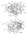
- FIGS. 1 and 2 illustrate the LC fiber optic block-out device 20 of the present invention.
- the block-out device 20 includes two identical block-out covers 30. Each block-out cover 30 has a front portion 32 and a back portion 34 with an open area 36 therebetween.
- the block-out device 20 also includes a front member 22 or bar that interconnects the front portions 32 of the block-out covers 30.
- the front member 22 of the block-out device 20 is substantially rectangular with an open area 24 at each side for receiving a removal tool 160.
- the front member 22 of the block-out device 20 also includes a removal tool attachment or connection member 26.
- the attachment member 26 includes a downwardly facing hook 28 (see FIG. 11 ) for engaging the removal tool 160. As described below, the attachment member 26 enables the removal tool 160 to be attached to the block-out device 20 for easy removal from the adapter 100.
- the front portion 32 and the back portion 34 of each block-out cover 30 includes a top 40, a bottom 70, sidewalls 80 and a back 90.
- a molded spring latch or locking arm 42 extends from the top 40 of the back portion 34 of each block-out cover 30.
- the molded spring latches 42 include a first portion 44, a second portion 48 and a third portion 56.
- the first portion 44 includes a vertically extending member 46 that extends upward from the top 40 of the block-out cover 30.
- the second portion 48 includes a horizontally extending member 50 and an upwardly extending member 52 with a shoulder 54.
- the horizontally extending member 50 extends from one end of the first portion 44 to one end of the upwardly extending member 52.
- the upwardly extending member 52 extends from the horizontally extending member 50 upwards toward the front portion 32 of the block-out cover 30.
- the third portion 56 includes a downwardly extending member 58 that extends downwardly from one end of the upwardly extending member 52 of the second portion 48.
- the downwardly extending member 58 is substantially parallel to the vertically extending member 46 of the spring latch 42.
- the downwardly extending member 58 is positioned within the open area 36 between the front portion 32 and the back portion 34 of the block-out cover 30.
- the third portion 56 also includes a flange 60 that extends outwardly toward the outer sidewall 84 of the block-out cover 30.
- each front portion 32 of the block-out covers 30 include a sealing member 62.
- the sealing members 62 are designed to matingly engage the openings 102 in a LC fiber optic duplex adapter 100 thereby preventing the adapter 100 from becoming contaminated.
- the sealing members 62 are spaced from the spring latches 42 with the opening area 36 therebetween.
- the sealing members 62 include a vertical portion 64, a horizontal portion 66 and an arcuate or sloped portion 68 that extends from the vertical portion 64 to the front member 22 of the block-out device 20.
- the front portion 32 and the back portion 34 of the block-out covers include an inner sidewall 82 and an outer sidewall 84 with the open area 36 therebetween.
- the outer sidewall 84 of the front portion 32 includes a stepped receiving area 86. As discussed below, each stepped receiving area 86 receives one of the prongs 180 of the removal tool 160.
- each block-out cover 30 includes a rectangular cross section 92 with a circular opening 94. As discussed below, the circular openings 94 receive the ferrule holders 108 in the adapter 100 when the block-out device 20 is installed in the adapter 100.
- FIGS. 3-6 illustrate the block-out device 20 of the present invention with the LC fiber optic duplex adapter 100.
- FIG. 3 illustrates the block-out device 20 installed in the LC fiber optic duplex adapter 100.
- FIG. 4 illustrates an exploded view of the adapter 100 and the block-out device 20.
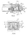
- FIGS. 5 and 6 illustrate a cross sectional view of the block-out device 20 installed in the adapter 100.
- the upwardly extending member 52 of the spring latches 42 are deflected downward in the open area 36 as the block-out device 20 passes the latch 106 extending from the top surface 104 of the adapter 100.
- the upwardly extending members 52 of the spring latches 42 return to their original position. As illustrated in FIG. 5 , the shoulder 54 of the upwardly extending member 52 is positioned behind the latch 106 extending from the top surface 104 of the adapter 100. As a result, the block-out device 20 is locked in the adapter 100 thereby protecting the adapter 100 from contamination, damage or misuse.
- FIG. 5 also illustrates the circular opening 94 of the back 90 of the block-out cover 30 receiving the ferrule holder 108 in the adapter 100.
- FIGS. 7-15 illustrate the block-out device 20 with the fiber optic duplex adapter 100 and the removal tool 160.
- the removal tool 160 is similar to the removal tool described in commonly owned U.S. Patent Application No. 11/207,853 , the contents of which are herein incorporated by reference.
- FIG. 7 illustrates the removal tool 160 positioned to be inserted in the tool insertion slots 120 defined by the outer sidewalls 84 of the front portions 32 of the block-out covers 30 and the LC fiber optic duplex adapter 100.
- the removal tool 160 includes a body 162 with an opening 164 in the center of the removal tool 160 and angled front edges 166, 168.
- the removal tool 160 also includes a release lever 170 positioned within the opening 164 and prongs 180 that extend outwardly from the front edge 166 of the removal tool 160.
- the release lever 170 has a raised knob 172 located near the center of the lever 170 and an upwardly facing hook 174 located at the free end of the lever 170.
- the prongs 180 include an inner side 182, an outer side 184 and a front end 186.
- the inner side 182 of each prong includes a curved or cam surface 190 that extends from the front end 186 of each prong 180 downwards towards the front edge 166 of the tool 160.
- FIGS. 8-11 illustrate the removal tool 160 partially installed in the block-out device 20.
- the prongs 180 engage the flanges 60 extending outwardly from the downwardly extending members 58 of the spring latches 42 to deflect the spring latches 42.
- the hook 174 of the release lever 170 contacts the attachment member 26 (see FIG. 11 ) extending from the front member 22 of the block-out device 20.
- FIGS. 12 and 13 illustrate the removal tool 160 fully installed in the block-out device 20.
- the prongs 180 of the removal tool 160 engage the flanges 60 extending from the downwardly extending member 58 to deflect the upwardly extending member 52 and shoulder 54 downward away from the latch 106 extending from the top 104 of the adapter 100.
- the hook 174 of the removal tool 160 engages the hook 28 of the attachment member 26 to secure the removal tool 160 to the block-out device 20.
- the block-out device 20 and attached removal tool 160 may be removed from the adapter 100.
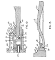
- the raised knob 172 of the release lever 170 may be depressed to disengage the hook 174 of the removal tool 160 from the hook 28 of the attachment member 26 extending from the front member 22 of the block-out device 20.
- the removal tool and the block-out device of the present invention provide a safe and secure device for blocking fiber optic adapters.
- the block-out device is designed so that it may only be removed with the two pronged removal tool. As a result, the block-out device would not accidentally or undesirably be removed by various available tools, such as a screwdriver or other flat tool.
Landscapes
- Physics & Mathematics (AREA)
- General Physics & Mathematics (AREA)
- Optics & Photonics (AREA)
- Mechanical Coupling Of Light Guides (AREA)
Abstract
Description
- The present invention relates to a block-out device, and more particularly to a block-out device for a fiber optic adapter.
- Block-out covers are frequently inserted into jack modules to protect the jack module and prevent entry of undesirable objects. Some covers include multiple parts or special latch connectors that secure the cover to the jack modules. Other covers have relatively large open areas designed to receive a flat tool that would enable the end user to release the cover from the jack module so that it could be removed from the jack module. The covers with the larger open areas, however, may be accidentally removed from the jack module. There are also covers that are inserted in the opening of a jack module and then locked by a rotating key. These covers may only be removed by inserting the key and rotating it to unlock or release the cover from the jack module.
- Dust covers or block-out covers have also been used to prevent optical fiber adapters and connectors from being contaminated. The prior art dust covers often do not provide an adequate seal thereby allowing dust or other material to contaminate the adapter or the connector. Prior art dust covers are also typically difficult to install and remove from the adapter or the connector.
- Thus, it is desirable to provide a tamper resistant block-out cover for a fiber optic adapter that prevents contamination, damage or misuse of the adapter. It would also be desirable to provide a block-out cover and a removal tool where the cover would not be accidentally removed from the adapter but would be easily removed from the adapter by a simple tool.
- The present invention is directed towards a device that protects an adapter from contamination, damage or misuse. The device includes a front member having an opening for receiving a removal tool. The device also includes cover members with a front portion and a back portion. The front member of the device interconnects the front portions of the cover members. The back portion of each cover member includes an arm extending upwardly therefrom for engaging the adapter to secure the device within the adapter. The arm also includes a downwardly extending member with a flange positioned at an end. The front portion of each cover member includes a sealing member for sealing an opening in the adapter when the cover member is installed within the adapter.
- According to one aspect of this invention, there is provided a device for covering a fiber optic adapter, the device comprising:
- at least one cover having a top, a bottom, sidewalls and a back, wherein the top of the cover includes a locking arm extending therefrom, the locking arm having a first portion, a second portion including an upwardly extending member extending from the first portion and a third portion including a downwardly extending member extending from the second portion; and
- a front member integrally connected to the cover.
- Optionally, the downwardly extending member of the third portion includes a flange extending outwardly towards one of the sidewalls of the cover.
- Optionally, the top further includes a sealing member for partially sealing an opening in the adapter, the sealing member having a vertical portion, a horizontal portion and an arcuate portion extending from the vertical portion to the front member.
- Optionally, the front member includes an attachment member for receiving a removal tool.
- Optionally, the device includes two covers for covering openings in the fiber optic adapter.
- According to a second aspect of this invention, there is provided a cover for an adapter, the cover comprising:
- a front portion and a back portion with an opening therebetween;
- an arm extending from the back portion, the arm for engaging a latch within the adapter upon installation of the cover within the adapter;
- a flange positioned at an end of the arm for disengaging the cover from the adapter; and
- a sealing member extending from the front portion, the sealing member for sealing an opening in the adapter when the cover is installed within the adapter.
- Optionally, the arm includes a first portion having a vertically extending member, a second portion extending from the first portion, the second portion having a horizontally extending member and an upwardly extending member and a third portion having a downwardly extending member extending from the second portion.
- Optionally, the sealing member includes a vertical portion, a horizontal portion and an arcuate portion.
- Optionally, the cover further comprises a front member, the front member having an attachment member for receiving a removal tool.
- According to a third aspect of this invention, there is provided a device for an adapter, the device comprising:
- a front member comprising an opening for receiving a removal tool;
- cover members having a front portion and a back portion, wherein the front member of the device interconnects the front portions of the cover members; and
- the back portion having an arm extending upwardly therefrom for engaging the adapter to secure the device within the adapter.
- Optionally, the device includes an open area between the front portion and the back portion, the arm extends downward and is positioned within the open area.
- Optionally, the arm comprises a first portion having a vertically extending member, a second portion extending from the first portion, the second portion having a horizontally extending member and an upwardly extending member and a third portion including a downwardly extending member extending from the second portion.
- Optionally, the downwardly extending member includes a flange positioned at an end for disengaging the cover member from the adapter.
- Optionally, the front portion further comprises a sealing member for sealing an opening in the adapter when the cover member is installed within the adapter.
- Optionally, the sealing member includes a vertical portion, a horizontal portion and an arcuate portion.
- Optionally, the front member includes an attachment member for receiving a removal tool.
- It is envisaged that features of each aspect of the invention may also be features of each other aspect of the invention. For example, it is envisaged that essential and optional features of the second and third aspects may also be features of certain embodiments of the first aspect.
-
-
FIG. 1 illustrates a front perspective view of the fiber optic block-out device of the present invention; -
FIG. 2 illustrates a rear perspective view of the fiber optic block-out device ofFIG. 1 ; -
FIG. 3 illustrates a front perspective view of the fiber optic block-out device ofFIG. 1 installed in a fiber optic adapter; -
FIG. 4 illustrates an exploded view of the fiber optic block-out device and adapter ofFIG. 3 ; -
FIG. 5 illustrates a cross sectional view of the fiber optic block-out device and adapter taken along line 5-5 inFIG. 3 ; -
FIG. 6 illustrates a cross sectional view of the fiber optic block-out device and adapter taken along line 6-6 inFIG. 5 ; -
FIG. 7 illustrates a front perspective view of the fiber optic block-out device ofFIG. 1 installed in the adapter and a block-out removal tool positioned to be installed in the device; -
FIG. 8 illustrates a front perspective view of the block-out removal tool partially installed in the fiber optic block-out device ofFIG. 7 ; -
FIG. 9 illustrates a top plan view of the block-out removal tool partially installed in the fiber optic block-out device ofFIG. 8 ; -
FIG. 10 illustrates a cross sectional view of the block-out removal tool partially installed in the fiber optic block-out device taken along line 10-10 ofFIG. 9 ; -
FIG. 11 illustrates a cross sectional view of the block-out removal tool partially installed in the fiber optic block-out device taken along line 11-11 ofFIG. 9 ; -
FIG. 12 illustrates a cross sectional view of the block-out removal tool installed in the fiber optic block-out device ofFIG. 7 ; -
FIG. 13 illustrates a cross sectional view of the block-out removal tool installed in the fiber optic block-out device ofFIG. 7 ; -
FIG. 14 illustrates a cross sectional view of the block-out removal tool installed in the fiber optic block-out device ofFIG. 12 being removed from the adapter; and -
FIG. 15 illustrates a cross sectional view of the block-out removal tool ofFIG. 14 released from the fiber optic block-out device. -
FIGS. 1 and 2 illustrate the LC fiber optic block-outdevice 20 of the present invention. The block-outdevice 20 includes two identical block-out covers 30. Each block-out cover 30 has afront portion 32 and aback portion 34 with anopen area 36 therebetween. The block-outdevice 20 also includes afront member 22 or bar that interconnects thefront portions 32 of the block-out covers 30. - The
front member 22 of the block-outdevice 20 is substantially rectangular with anopen area 24 at each side for receiving aremoval tool 160. Thefront member 22 of the block-outdevice 20 also includes a removal tool attachment orconnection member 26. Theattachment member 26 includes a downwardly facing hook 28 (seeFIG. 11 ) for engaging theremoval tool 160. As described below, theattachment member 26 enables theremoval tool 160 to be attached to the block-outdevice 20 for easy removal from theadapter 100. - The
front portion 32 and theback portion 34 of each block-out cover 30 includes a top 40, a bottom 70, sidewalls 80 and a back 90. A molded spring latch or lockingarm 42 extends from the top 40 of theback portion 34 of each block-out cover 30. As illustrated inFIGS. 1 and 2 , the molded spring latches 42 include afirst portion 44, asecond portion 48 and athird portion 56. Thefirst portion 44 includes a vertically extendingmember 46 that extends upward from the top 40 of the block-out cover 30. Thesecond portion 48 includes a horizontally extendingmember 50 and an upwardly extendingmember 52 with ashoulder 54. The horizontally extendingmember 50 extends from one end of thefirst portion 44 to one end of the upwardly extendingmember 52. The upwardly extendingmember 52 extends from the horizontally extendingmember 50 upwards toward thefront portion 32 of the block-out cover 30. Thethird portion 56 includes a downwardly extendingmember 58 that extends downwardly from one end of the upwardly extendingmember 52 of thesecond portion 48. The downwardly extendingmember 58 is substantially parallel to the vertically extendingmember 46 of thespring latch 42. The downwardly extendingmember 58 is positioned within theopen area 36 between thefront portion 32 and theback portion 34 of the block-out cover 30. Thethird portion 56 also includes aflange 60 that extends outwardly toward theouter sidewall 84 of the block-out cover 30. - The top 40 of each
front portion 32 of the block-out covers 30 include a sealingmember 62. As illustrated inFIG. 3 , the sealingmembers 62 are designed to matingly engage theopenings 102 in a LC fiberoptic duplex adapter 100 thereby preventing theadapter 100 from becoming contaminated. The sealingmembers 62 are spaced from the spring latches 42 with theopening area 36 therebetween. The sealingmembers 62 include avertical portion 64, a horizontal portion 66 and an arcuate or slopedportion 68 that extends from thevertical portion 64 to thefront member 22 of the block-outdevice 20. - The
front portion 32 and theback portion 34 of the block-out covers include aninner sidewall 82 and anouter sidewall 84 with theopen area 36 therebetween. Theouter sidewall 84 of thefront portion 32 includes a stepped receiving area 86. As discussed below, each stepped receiving area 86 receives one of theprongs 180 of theremoval tool 160. - The
back 90 of each block-out cover 30 includes arectangular cross section 92 with acircular opening 94. As discussed below, thecircular openings 94 receive theferrule holders 108 in theadapter 100 when the block-outdevice 20 is installed in theadapter 100. -
FIGS. 3-6 illustrate the block-outdevice 20 of the present invention with the LC fiberoptic duplex adapter 100.FIG. 3 illustrates the block-outdevice 20 installed in the LC fiberoptic duplex adapter 100.FIG. 4 illustrates an exploded view of theadapter 100 and the block-outdevice 20.FIGS. 5 and 6 illustrate a cross sectional view of the block-outdevice 20 installed in theadapter 100. As the block-outdevice 20 is being installed in theadapter 100, the upwardly extendingmember 52 of the spring latches 42 are deflected downward in theopen area 36 as the block-outdevice 20 passes thelatch 106 extending from thetop surface 104 of theadapter 100. Once the spring latches 42 clear thelatch 106 extending from thetop surface 104 of theadapter 100, the upwardly extendingmembers 52 of the spring latches 42 return to their original position. As illustrated inFIG. 5 , theshoulder 54 of the upwardly extendingmember 52 is positioned behind thelatch 106 extending from thetop surface 104 of theadapter 100. As a result, the block-outdevice 20 is locked in theadapter 100 thereby protecting theadapter 100 from contamination, damage or misuse. -
FIG. 5 also illustrates thecircular opening 94 of theback 90 of the block-out cover 30 receiving theferrule holder 108 in theadapter 100. -
FIGS. 7-15 illustrate the block-outdevice 20 with the fiberoptic duplex adapter 100 and theremoval tool 160. Theremoval tool 160 is similar to the removal tool described in commonly ownedU.S. Patent Application No. 11/207,853 , the contents of which are herein incorporated by reference.FIG. 7 illustrates theremoval tool 160 positioned to be inserted in thetool insertion slots 120 defined by theouter sidewalls 84 of thefront portions 32 of the block-out covers 30 and the LC fiberoptic duplex adapter 100. - The
removal tool 160 includes abody 162 with anopening 164 in the center of theremoval tool 160 and angled front edges 166, 168. Theremoval tool 160 also includes arelease lever 170 positioned within theopening 164 andprongs 180 that extend outwardly from the front edge 166 of theremoval tool 160. Therelease lever 170 has a raisedknob 172 located near the center of thelever 170 and an upwardly facinghook 174 located at the free end of thelever 170. Theprongs 180 include aninner side 182, anouter side 184 and a front end 186. Theinner side 182 of each prong includes a curved orcam surface 190 that extends from the front end 186 of eachprong 180 downwards towards the front edge 166 of thetool 160. -
FIGS. 8-11 illustrate theremoval tool 160 partially installed in the block-outdevice 20. As theremoval tool 160 is installed in the block-outdevice 20, theprongs 180 engage theflanges 60 extending outwardly from the downwardly extendingmembers 58 of the spring latches 42 to deflect the spring latches 42. Also, as theremoval tool 160 is installed, thehook 174 of therelease lever 170 contacts the attachment member 26 (seeFIG. 11 ) extending from thefront member 22 of the block-outdevice 20. -
FIGS. 12 and 13 illustrate theremoval tool 160 fully installed in the block-outdevice 20. When theremoval tool 160 is fully installed, theprongs 180 of theremoval tool 160 engage theflanges 60 extending from the downwardly extendingmember 58 to deflect the upwardly extendingmember 52 andshoulder 54 downward away from thelatch 106 extending from the top 104 of theadapter 100. Thehook 174 of theremoval tool 160 engages thehook 28 of theattachment member 26 to secure theremoval tool 160 to the block-outdevice 20. - As illustrated in
FIG. 14 , once theremoval tool 160 is fully installed and the spring latches 42 have been deflected, the block-outdevice 20 and attachedremoval tool 160 may be removed from theadapter 100. As illustrated inFIG. 15 , once the block-outdevice 20 has been removed from theadapter 100, the raisedknob 172 of therelease lever 170 may be depressed to disengage thehook 174 of theremoval tool 160 from thehook 28 of theattachment member 26 extending from thefront member 22 of the block-outdevice 20. - The removal tool and the block-out device of the present invention provide a safe and secure device for blocking fiber optic adapters. The block-out device is designed so that it may only be removed with the two pronged removal tool. As a result, the block-out device would not accidentally or undesirably be removed by various available tools, such as a screwdriver or other flat tool.
- Furthermore, while the particular preferred embodiments of the present invention have been shown and described, it will be obvious to those skilled in the art that changes and modifications may be made without departing from the teaching of the invention. The matter set forth in the foregoing description and accompanying drawings is offered by way of illustration only and not as limitation. The actual scope of the invention is intended to be defined in the following claims when viewed in their proper perspective based on the prior art.
Claims (5)
- A device for covering a fiber optic adapter, the device comprising:at least one cover having a top, a bottom, sidewalls and a back, wherein the top of the cover includes a locking arm extending therefrom, the locking arm having a first portion, a second portion including an upwardly extending member extending from the first portion and a third portion including a downwardly extending member extending from the second portion; anda front member integrally connected to the cover.
- The device of claim 1, wherein the downwardly extending member of the third portion includes a flange extending outwardly towards one of the sidewalls of the cover.
- The device of claim 1, wherein the top further includes a sealing member for partially sealing an opening in the adapter, the sealing member having a vertical portion, a horizontal portion and an arcuate portion extending from the vertical portion to the front member.
- The device of claim 1, wherein the front member includes an attachment member for receiving a removal tool.
- The device of claim 1, wherein the device includes two covers for covering openings in the fiber optic adapter.
Applications Claiming Priority (1)
| Application Number | Priority Date | Filing Date | Title |
|---|---|---|---|
| US12/404,768 US7993063B2 (en) | 2009-03-16 | 2009-03-16 | Block-out device for fiber optic adapter |
Publications (2)
| Publication Number | Publication Date |
|---|---|
| EP2230543A1 true EP2230543A1 (en) | 2010-09-22 |
| EP2230543B1 EP2230543B1 (en) | 2015-11-25 |
Family
ID=42236765
Family Applications (1)
| Application Number | Title | Priority Date | Filing Date |
|---|---|---|---|
| EP10156431.8A Not-in-force EP2230543B1 (en) | 2009-03-16 | 2010-03-12 | Block-out device for fiber optic adapter |
Country Status (4)
| Country | Link |
|---|---|
| US (2) | US7993063B2 (en) |
| EP (1) | EP2230543B1 (en) |
| JP (1) | JP5538005B2 (en) |
| CN (1) | CN101846775B (en) |
Cited By (2)
| Publication number | Priority date | Publication date | Assignee | Title |
|---|---|---|---|---|
| FR3056026A1 (en) * | 2016-09-15 | 2018-03-16 | Bull Sas | LOCK FOR LOCKING AN ELECTRICITY AND / OR TELECOMMUNICATION NETWORK OUTLET |
| RU217342U1 (en) * | 2022-12-20 | 2023-03-28 | Открытое Акционерное Общество "Российские Железные Дороги" | LC optical connector extraction tool |
Families Citing this family (19)
| Publication number | Priority date | Publication date | Assignee | Title |
|---|---|---|---|---|
| CN102346279B (en) * | 2010-07-30 | 2015-03-11 | 株式会社藤仓 | Optical connector and connector connection system |
| JP5771075B2 (en) * | 2010-12-28 | 2015-08-26 | 矢崎総業株式会社 | Optical connector |
| JP2012220731A (en) * | 2011-04-08 | 2012-11-12 | Yazaki Corp | Optical connector |
| TWM413736U (en) * | 2011-04-21 | 2011-10-11 | Farng Yiing Entpr Co Ltd | Safety lock assembly of communication wiring |
| TW201246702A (en) * | 2011-05-06 | 2012-11-16 | Ct Prec Co Ltd | Protective cover body and removal tool |
| WO2013173726A1 (en) * | 2012-05-18 | 2013-11-21 | Adc Telecommunications, Inc. | Connectors and adapters with auto-latching features |
| JP6294310B2 (en) * | 2012-05-21 | 2018-03-14 | アドヴァンスド ファイバー プロダクツ、エルエルシーAdvanced Fiber Products,Llc | Safety SC optical fiber connector and removal tool |
| US8873921B2 (en) * | 2012-12-07 | 2014-10-28 | Hsing Chau Industrial Co., Ltd. | Optical fiber adapter security, optical fiber connector security, and removal tool for use therewith |
| JP5453568B1 (en) * | 2013-11-25 | 2014-03-26 | 達哉 芦川 | OBD connector protective cover |
| JP6311623B2 (en) * | 2015-02-06 | 2018-04-18 | 株式会社オートネットワーク技術研究所 | connector |
| EP3265857B1 (en) | 2015-11-24 | 2022-01-19 | Hewlett Packard Enterprise Development LP | Interfacing a ferrule with a socket |
| CN205374820U (en) * | 2016-02-01 | 2016-07-06 | 上海光联通讯技术有限公司 | Optical fiber adapter |
| WO2017146722A1 (en) | 2016-02-26 | 2017-08-31 | Hewlett Packard Enterprise Development Lp | Optical connector assembly |
| US10678006B2 (en) | 2016-09-30 | 2020-06-09 | Hewlett Packard Enterprise Development Lp | Optical interfaces with solder that passively aligns optical socket |
| US10795091B2 (en) | 2017-07-14 | 2020-10-06 | Hewlett Packard Enterprise Development Lp | Adaptor for optical component of optical connector |
| JP7036772B2 (en) * | 2019-05-27 | 2022-03-15 | 矢崎総業株式会社 | Optical connector |
| TWI771260B (en) * | 2022-01-13 | 2022-07-11 | 新橋實業股份有限公司 | Protection components for fiber optic sockets |
| US11817667B1 (en) * | 2022-12-28 | 2023-11-14 | Rivian Ip Holdings, Llc | High voltage connector service extraction tool |
| TWI880256B (en) * | 2023-06-29 | 2025-04-11 | 新橋實業股份有限公司 | Connector socket protection assembly and protection plug cover |
Citations (3)
| Publication number | Priority date | Publication date | Assignee | Title |
|---|---|---|---|---|
| US20050232551A1 (en) * | 2004-04-16 | 2005-10-20 | Cheng-Pei Chang | Devices for preventing lens contamination in optoelectronic modules and connectors |
| US20060040564A1 (en) * | 2004-08-19 | 2006-02-23 | Morrison David S | Block-out cover and removal tool |
| US20080310795A1 (en) * | 2007-06-13 | 2008-12-18 | Parkman Iii Louis Edward | Dust cap for fiber optic adapter |
Family Cites Families (48)
| Publication number | Priority date | Publication date | Assignee | Title |
|---|---|---|---|---|
| US3570096A (en) * | 1968-04-26 | 1971-03-16 | Thomas & Betts Corp | Module extraction tool |
| US3951514A (en) * | 1974-12-23 | 1976-04-20 | International Telephone And Telegraph Corporation | Connector member |
| US4084882A (en) * | 1976-08-30 | 1978-04-18 | International Telephone And Telegraph Corporation | Connector member |
| US4311883A (en) * | 1980-03-10 | 1982-01-19 | Kidney Susan L | Modular telephone jack lock |
| GB8408097D0 (en) * | 1984-03-29 | 1984-05-10 | Allied Corp | Electrical junction housings |
| US5076656A (en) * | 1984-06-08 | 1991-12-31 | Briggs Robert C | High precision optical fiber connectors |
| JPS62172671A (en) * | 1986-01-27 | 1987-07-29 | 松下電工株式会社 | Connectiong jack for telephone line |
| US4789348A (en) * | 1987-09-30 | 1988-12-06 | Siecor Corporation | Modular connector with unitary dust cover |
| US4846708A (en) * | 1988-02-11 | 1989-07-11 | Michigan Bell Telephone Company | Jack security device |
| US4887972A (en) * | 1989-01-12 | 1989-12-19 | Northern Telecom Limited | Snap-together enclosure for a telephone jack receptacle |
| US4870840A (en) * | 1989-02-06 | 1989-10-03 | Edward Klein | Modular communications jack lock |
| IE893328A1 (en) * | 1989-10-16 | 1991-04-24 | Mcdaid Denis | Telephone lock |
| US5190465A (en) * | 1991-09-19 | 1993-03-02 | International Business Machines Corp. | Cable locking covers |
| US5220815A (en) * | 1991-09-19 | 1993-06-22 | International Business Machines Corporation | Device-port locking covers |
| US5305380A (en) * | 1992-05-20 | 1994-04-19 | Sun Microsystems, Inc. | Methods and apparatus for providing a secure telecommunications port |
| AU663014B2 (en) * | 1992-11-26 | 1995-09-21 | Diamond S.A. | Plug connector for an optical fibre |
| US5265328A (en) * | 1992-12-11 | 1993-11-30 | Stratos Product Development Group, Inc. | Circuit module extraction tool and method |
| US5340324A (en) * | 1993-03-23 | 1994-08-23 | Fields James H | Phone jack lock |
| US5429522A (en) * | 1994-01-21 | 1995-07-04 | Burndy Corporation | Protected communications socket |
| US5556295A (en) * | 1995-02-17 | 1996-09-17 | Dynametric, Inc. | Modular plug locking system |
| US5637002A (en) * | 1995-09-15 | 1997-06-10 | Buck; Charles T. | Self locking and ejecting RJ-11 plug |
| US5984705A (en) * | 1996-12-02 | 1999-11-16 | Sumitomo Wiring Systems, Ltd. | Connector |
| US6227717B1 (en) * | 1997-12-16 | 2001-05-08 | The Siemon Company | Dust caps for use with telecommunications adapters and connectors |
| US6019521A (en) * | 1998-02-09 | 2000-02-01 | The Whitaker Corporation | Optical fiber connector |
| US6079881A (en) * | 1998-04-08 | 2000-06-27 | Molex Incorporated | Fiber optic connector receptacle assembly |
| US6464408B1 (en) * | 1998-12-28 | 2002-10-15 | Computer Crafts, Inc. | Fiber optic connectors |
| US6789950B1 (en) * | 1999-12-01 | 2004-09-14 | 3M Innovative Properties Company | Optical fiber connector system |
| US7076144B2 (en) * | 1999-12-01 | 2006-07-11 | 3M Innovative Properties Company | Apparatus and method for controlling the bend radius of an optical fiber cable |
| US6913393B2 (en) * | 2000-08-08 | 2005-07-05 | Tyco Electronics Amp Gmbh | Protective device in a connector arrangement for optical fibers |
| TW461612U (en) * | 2000-08-08 | 2001-10-21 | Hon Hai Prec Ind Co Ltd | Socket connector |
| US6511231B2 (en) * | 2000-12-27 | 2003-01-28 | Fitel Usa Corp. | Optical connector receptacle having switching capability |
| US6942395B1 (en) * | 2001-01-29 | 2005-09-13 | Jds Uniphase Corporation | Method and apparatus of pull-lever release for fiber optic modules |
| ATE366945T1 (en) * | 2001-03-01 | 2007-08-15 | Huber+Suhner Ag | FIBER OPTICAL CONNECTOR SYSTEM |
| US6890206B2 (en) * | 2002-03-05 | 2005-05-10 | Jds Uniphase Corporation | Optical transceiver latch |
| US6918703B2 (en) * | 2002-06-12 | 2005-07-19 | Molex Incorporated | System for terminating optical fibers in a fiber optic connector |
| JP3600223B2 (en) * | 2002-06-27 | 2004-12-15 | 株式会社アイティティキャノン | Multi-core connector |
| US7074066B2 (en) * | 2004-03-29 | 2006-07-11 | Tyco Electronics Corporation | Sealed electrical connector having internal latching mechanism therefore |
| TWM260035U (en) * | 2004-07-27 | 2005-03-21 | Sheng-Shing Liau | Telephone plug structure with locking functions |
| JP2006039444A (en) * | 2004-07-30 | 2006-02-09 | Yazaki Corp | Insertion / extraction tool for adapter for optical connector |
| CN100433469C (en) * | 2004-08-19 | 2008-11-12 | 泛达公司 | Protective cover and removal tool |
| JP4821209B2 (en) * | 2005-04-14 | 2011-11-24 | 住友電気工業株式会社 | Optical connector and optical connector assembling method |
| EP1762871B1 (en) | 2005-09-12 | 2009-01-07 | Reichle & De-Massari AG | Secured connector system |
| US7354291B2 (en) * | 2006-03-01 | 2008-04-08 | Panduit Corp. | Plug locking assembly |
| US7338214B1 (en) * | 2006-08-25 | 2008-03-04 | Tyco Electronics Corporation | Method and apparatus for sealing fiber optic connectors for industrial applications |
| US7543995B2 (en) * | 2006-12-19 | 2009-06-09 | Finisar Corporation | Optical subassembly connector block for an optoelectronic module |
| US7806706B2 (en) * | 2007-07-03 | 2010-10-05 | Panduit Corp. | Plug locking assembly and system |
| US7632125B2 (en) * | 2007-08-17 | 2009-12-15 | Panduit Corp. | Plug locking assembly |
| US7744286B2 (en) * | 2007-12-11 | 2010-06-29 | Adc Telecommunications, Inc. | Hardened fiber optic connection system with multiple configurations |
-
2009
- 2009-03-16 US US12/404,768 patent/US7993063B2/en not_active Expired - Fee Related
-
2010
- 2010-03-12 EP EP10156431.8A patent/EP2230543B1/en not_active Not-in-force
- 2010-03-15 JP JP2010057533A patent/JP5538005B2/en not_active Expired - Fee Related
- 2010-03-16 CN CN201010190088.XA patent/CN101846775B/en not_active Expired - Fee Related
-
2011
- 2011-07-19 US US13/185,973 patent/US8277128B2/en not_active Expired - Fee Related
Patent Citations (3)
| Publication number | Priority date | Publication date | Assignee | Title |
|---|---|---|---|---|
| US20050232551A1 (en) * | 2004-04-16 | 2005-10-20 | Cheng-Pei Chang | Devices for preventing lens contamination in optoelectronic modules and connectors |
| US20060040564A1 (en) * | 2004-08-19 | 2006-02-23 | Morrison David S | Block-out cover and removal tool |
| US20080310795A1 (en) * | 2007-06-13 | 2008-12-18 | Parkman Iii Louis Edward | Dust cap for fiber optic adapter |
Cited By (3)
| Publication number | Priority date | Publication date | Assignee | Title |
|---|---|---|---|---|
| FR3056026A1 (en) * | 2016-09-15 | 2018-03-16 | Bull Sas | LOCK FOR LOCKING AN ELECTRICITY AND / OR TELECOMMUNICATION NETWORK OUTLET |
| EP3297099A1 (en) * | 2016-09-15 | 2018-03-21 | Bull Sas | Latch for locking a connector in an electrical and/or telecommunication network |
| RU217342U1 (en) * | 2022-12-20 | 2023-03-28 | Открытое Акционерное Общество "Российские Железные Дороги" | LC optical connector extraction tool |
Also Published As
| Publication number | Publication date |
|---|---|
| US7993063B2 (en) | 2011-08-09 |
| EP2230543B1 (en) | 2015-11-25 |
| US20110274401A1 (en) | 2011-11-10 |
| CN101846775B (en) | 2014-03-26 |
| JP5538005B2 (en) | 2014-07-02 |
| US8277128B2 (en) | 2012-10-02 |
| CN101846775A (en) | 2010-09-29 |
| US20100232756A1 (en) | 2010-09-16 |
| JP2010217894A (en) | 2010-09-30 |
Similar Documents
| Publication | Publication Date | Title |
|---|---|---|
| EP2230543B1 (en) | Block-out device for fiber optic adapter | |
| US8224146B2 (en) | Block-out device for fiber optic adapter | |
| EP1782506B1 (en) | Removal tool for block-out cover | |
| US7632125B2 (en) | Plug locking assembly | |
| EP2859625B1 (en) | Connector assembly and connector product | |
| JP6294310B2 (en) | Safety SC optical fiber connector and removal tool | |
| EP2572221B1 (en) | Locking optical and/or electrical connectors and cable assemblies | |
| US20130102167A1 (en) | Blockout Device for USB Port | |
| WO2010151303A1 (en) | Security seal | |
| CN100433469C (en) | Protective cover and removal tool | |
| US9726832B2 (en) | Secure SC optical fiber connector and removal tools | |
| US6361242B1 (en) | Connector security latching mechanism | |
| EP1049210B1 (en) | Connector cover | |
| US12488152B1 (en) | Disarmable tamper evident port protector | |
| EP1093192B1 (en) | Detachable connector |
Legal Events
| Date | Code | Title | Description |
|---|---|---|---|
| PUAI | Public reference made under article 153(3) epc to a published international application that has entered the european phase |
Free format text: ORIGINAL CODE: 0009012 |
|
| AK | Designated contracting states |
Kind code of ref document: A1 Designated state(s): AT BE BG CH CY CZ DE DK EE ES FI FR GB GR HR HU IE IS IT LI LT LU LV MC MK MT NL NO PL PT RO SE SI SK SM TR |
|
| AX | Request for extension of the european patent |
Extension state: AL BA ME RS |
|
| 17P | Request for examination filed |
Effective date: 20110322 |
|
| 17Q | First examination report despatched |
Effective date: 20120601 |
|
| GRAP | Despatch of communication of intention to grant a patent |
Free format text: ORIGINAL CODE: EPIDOSNIGR1 |
|
| INTG | Intention to grant announced |
Effective date: 20150505 |
|
| GRAP | Despatch of communication of intention to grant a patent |
Free format text: ORIGINAL CODE: EPIDOSNIGR1 |
|
| INTG | Intention to grant announced |
Effective date: 20150703 |
|
| GRAS | Grant fee paid |
Free format text: ORIGINAL CODE: EPIDOSNIGR3 |
|
| GRAA | (expected) grant |
Free format text: ORIGINAL CODE: 0009210 |
|
| AK | Designated contracting states |
Kind code of ref document: B1 Designated state(s): AT BE BG CH CY CZ DE DK EE ES FI FR GB GR HR HU IE IS IT LI LT LU LV MC MK MT NL NO PL PT RO SE SI SK SM TR |
|
| REG | Reference to a national code |
Ref country code: GB Ref legal event code: FG4D |
|
| REG | Reference to a national code |
Ref country code: CH Ref legal event code: EP |
|
| REG | Reference to a national code |
Ref country code: AT Ref legal event code: REF Ref document number: 762883 Country of ref document: AT Kind code of ref document: T Effective date: 20151215 |
|
| REG | Reference to a national code |
Ref country code: IE Ref legal event code: FG4D |
|
| REG | Reference to a national code |
Ref country code: DE Ref legal event code: R096 Ref document number: 602010029122 Country of ref document: DE |
|
| REG | Reference to a national code |
Ref country code: LT Ref legal event code: MG4D |
|
| REG | Reference to a national code |
Ref country code: NL Ref legal event code: MP Effective date: 20160225 |
|
| REG | Reference to a national code |
Ref country code: AT Ref legal event code: MK05 Ref document number: 762883 Country of ref document: AT Kind code of ref document: T Effective date: 20151125 |
|
| PG25 | Lapsed in a contracting state [announced via postgrant information from national office to epo] |
Ref country code: ES Free format text: LAPSE BECAUSE OF FAILURE TO SUBMIT A TRANSLATION OF THE DESCRIPTION OR TO PAY THE FEE WITHIN THE PRESCRIBED TIME-LIMIT Effective date: 20151125 Ref country code: NO Free format text: LAPSE BECAUSE OF FAILURE TO SUBMIT A TRANSLATION OF THE DESCRIPTION OR TO PAY THE FEE WITHIN THE PRESCRIBED TIME-LIMIT Effective date: 20160225 Ref country code: IS Free format text: LAPSE BECAUSE OF FAILURE TO SUBMIT A TRANSLATION OF THE DESCRIPTION OR TO PAY THE FEE WITHIN THE PRESCRIBED TIME-LIMIT Effective date: 20160325 Ref country code: NL Free format text: LAPSE BECAUSE OF FAILURE TO SUBMIT A TRANSLATION OF THE DESCRIPTION OR TO PAY THE FEE WITHIN THE PRESCRIBED TIME-LIMIT Effective date: 20151125 Ref country code: HR Free format text: LAPSE BECAUSE OF FAILURE TO SUBMIT A TRANSLATION OF THE DESCRIPTION OR TO PAY THE FEE WITHIN THE PRESCRIBED TIME-LIMIT Effective date: 20151125 Ref country code: LT Free format text: LAPSE BECAUSE OF FAILURE TO SUBMIT A TRANSLATION OF THE DESCRIPTION OR TO PAY THE FEE WITHIN THE PRESCRIBED TIME-LIMIT Effective date: 20151125 |
|
| PG25 | Lapsed in a contracting state [announced via postgrant information from national office to epo] |
Ref country code: AT Free format text: LAPSE BECAUSE OF FAILURE TO SUBMIT A TRANSLATION OF THE DESCRIPTION OR TO PAY THE FEE WITHIN THE PRESCRIBED TIME-LIMIT Effective date: 20151125 Ref country code: LV Free format text: LAPSE BECAUSE OF FAILURE TO SUBMIT A TRANSLATION OF THE DESCRIPTION OR TO PAY THE FEE WITHIN THE PRESCRIBED TIME-LIMIT Effective date: 20151125 Ref country code: SE Free format text: LAPSE BECAUSE OF FAILURE TO SUBMIT A TRANSLATION OF THE DESCRIPTION OR TO PAY THE FEE WITHIN THE PRESCRIBED TIME-LIMIT Effective date: 20151125 Ref country code: PT Free format text: LAPSE BECAUSE OF FAILURE TO SUBMIT A TRANSLATION OF THE DESCRIPTION OR TO PAY THE FEE WITHIN THE PRESCRIBED TIME-LIMIT Effective date: 20160325 Ref country code: PL Free format text: LAPSE BECAUSE OF FAILURE TO SUBMIT A TRANSLATION OF THE DESCRIPTION OR TO PAY THE FEE WITHIN THE PRESCRIBED TIME-LIMIT Effective date: 20151125 Ref country code: GR Free format text: LAPSE BECAUSE OF FAILURE TO SUBMIT A TRANSLATION OF THE DESCRIPTION OR TO PAY THE FEE WITHIN THE PRESCRIBED TIME-LIMIT Effective date: 20160226 Ref country code: FI Free format text: LAPSE BECAUSE OF FAILURE TO SUBMIT A TRANSLATION OF THE DESCRIPTION OR TO PAY THE FEE WITHIN THE PRESCRIBED TIME-LIMIT Effective date: 20151125 |
|
| PG25 | Lapsed in a contracting state [announced via postgrant information from national office to epo] |
Ref country code: IT Free format text: LAPSE BECAUSE OF FAILURE TO SUBMIT A TRANSLATION OF THE DESCRIPTION OR TO PAY THE FEE WITHIN THE PRESCRIBED TIME-LIMIT Effective date: 20151125 Ref country code: CZ Free format text: LAPSE BECAUSE OF FAILURE TO SUBMIT A TRANSLATION OF THE DESCRIPTION OR TO PAY THE FEE WITHIN THE PRESCRIBED TIME-LIMIT Effective date: 20151125 |
|
| REG | Reference to a national code |
Ref country code: DE Ref legal event code: R097 Ref document number: 602010029122 Country of ref document: DE |
|
| PG25 | Lapsed in a contracting state [announced via postgrant information from national office to epo] |
Ref country code: RO Free format text: LAPSE BECAUSE OF FAILURE TO SUBMIT A TRANSLATION OF THE DESCRIPTION OR TO PAY THE FEE WITHIN THE PRESCRIBED TIME-LIMIT Effective date: 20151125 Ref country code: DK Free format text: LAPSE BECAUSE OF FAILURE TO SUBMIT A TRANSLATION OF THE DESCRIPTION OR TO PAY THE FEE WITHIN THE PRESCRIBED TIME-LIMIT Effective date: 20151125 Ref country code: BE Free format text: LAPSE BECAUSE OF NON-PAYMENT OF DUE FEES Effective date: 20160331 Ref country code: EE Free format text: LAPSE BECAUSE OF FAILURE TO SUBMIT A TRANSLATION OF THE DESCRIPTION OR TO PAY THE FEE WITHIN THE PRESCRIBED TIME-LIMIT Effective date: 20151125 Ref country code: SK Free format text: LAPSE BECAUSE OF FAILURE TO SUBMIT A TRANSLATION OF THE DESCRIPTION OR TO PAY THE FEE WITHIN THE PRESCRIBED TIME-LIMIT Effective date: 20151125 Ref country code: SM Free format text: LAPSE BECAUSE OF FAILURE TO SUBMIT A TRANSLATION OF THE DESCRIPTION OR TO PAY THE FEE WITHIN THE PRESCRIBED TIME-LIMIT Effective date: 20151125 |
|
| PLBE | No opposition filed within time limit |
Free format text: ORIGINAL CODE: 0009261 |
|
| STAA | Information on the status of an ep patent application or granted ep patent |
Free format text: STATUS: NO OPPOSITION FILED WITHIN TIME LIMIT |
|
| REG | Reference to a national code |
Ref country code: DE Ref legal event code: R119 Ref document number: 602010029122 Country of ref document: DE |
|
| PG25 | Lapsed in a contracting state [announced via postgrant information from national office to epo] |
Ref country code: MC Free format text: LAPSE BECAUSE OF FAILURE TO SUBMIT A TRANSLATION OF THE DESCRIPTION OR TO PAY THE FEE WITHIN THE PRESCRIBED TIME-LIMIT Effective date: 20151125 Ref country code: LU Free format text: LAPSE BECAUSE OF FAILURE TO SUBMIT A TRANSLATION OF THE DESCRIPTION OR TO PAY THE FEE WITHIN THE PRESCRIBED TIME-LIMIT Effective date: 20160312 |
|
| REG | Reference to a national code |
Ref country code: CH Ref legal event code: PL |
|
| 26N | No opposition filed |
Effective date: 20160826 |
|
| GBPC | Gb: european patent ceased through non-payment of renewal fee |
Effective date: 20160312 |
|
| PG25 | Lapsed in a contracting state [announced via postgrant information from national office to epo] |
Ref country code: SI Free format text: LAPSE BECAUSE OF FAILURE TO SUBMIT A TRANSLATION OF THE DESCRIPTION OR TO PAY THE FEE WITHIN THE PRESCRIBED TIME-LIMIT Effective date: 20151125 |
|
| REG | Reference to a national code |
Ref country code: IE Ref legal event code: MM4A |
|
| PG25 | Lapsed in a contracting state [announced via postgrant information from national office to epo] |
Ref country code: BE Free format text: LAPSE BECAUSE OF FAILURE TO SUBMIT A TRANSLATION OF THE DESCRIPTION OR TO PAY THE FEE WITHIN THE PRESCRIBED TIME-LIMIT Effective date: 20151125 |
|
| REG | Reference to a national code |
Ref country code: FR Ref legal event code: ST Effective date: 20161130 |
|
| PG25 | Lapsed in a contracting state [announced via postgrant information from national office to epo] |
Ref country code: IE Free format text: LAPSE BECAUSE OF NON-PAYMENT OF DUE FEES Effective date: 20160312 Ref country code: FR Free format text: LAPSE BECAUSE OF NON-PAYMENT OF DUE FEES Effective date: 20160331 Ref country code: LI Free format text: LAPSE BECAUSE OF NON-PAYMENT OF DUE FEES Effective date: 20160331 Ref country code: DE Free format text: LAPSE BECAUSE OF NON-PAYMENT OF DUE FEES Effective date: 20161001 Ref country code: CH Free format text: LAPSE BECAUSE OF NON-PAYMENT OF DUE FEES Effective date: 20160331 Ref country code: GB Free format text: LAPSE BECAUSE OF NON-PAYMENT OF DUE FEES Effective date: 20160312 |
|
| PG25 | Lapsed in a contracting state [announced via postgrant information from national office to epo] |
Ref country code: MT Free format text: LAPSE BECAUSE OF FAILURE TO SUBMIT A TRANSLATION OF THE DESCRIPTION OR TO PAY THE FEE WITHIN THE PRESCRIBED TIME-LIMIT Effective date: 20151125 |
|
| PG25 | Lapsed in a contracting state [announced via postgrant information from national office to epo] |
Ref country code: HU Free format text: LAPSE BECAUSE OF FAILURE TO SUBMIT A TRANSLATION OF THE DESCRIPTION OR TO PAY THE FEE WITHIN THE PRESCRIBED TIME-LIMIT; INVALID AB INITIO Effective date: 20100312 Ref country code: CY Free format text: LAPSE BECAUSE OF FAILURE TO SUBMIT A TRANSLATION OF THE DESCRIPTION OR TO PAY THE FEE WITHIN THE PRESCRIBED TIME-LIMIT Effective date: 20151125 |
|
| PG25 | Lapsed in a contracting state [announced via postgrant information from national office to epo] |
Ref country code: MK Free format text: LAPSE BECAUSE OF FAILURE TO SUBMIT A TRANSLATION OF THE DESCRIPTION OR TO PAY THE FEE WITHIN THE PRESCRIBED TIME-LIMIT Effective date: 20151125 Ref country code: TR Free format text: LAPSE BECAUSE OF FAILURE TO SUBMIT A TRANSLATION OF THE DESCRIPTION OR TO PAY THE FEE WITHIN THE PRESCRIBED TIME-LIMIT Effective date: 20151125 Ref country code: MT Free format text: LAPSE BECAUSE OF FAILURE TO SUBMIT A TRANSLATION OF THE DESCRIPTION OR TO PAY THE FEE WITHIN THE PRESCRIBED TIME-LIMIT Effective date: 20160331 |
|
| PG25 | Lapsed in a contracting state [announced via postgrant information from national office to epo] |
Ref country code: BG Free format text: LAPSE BECAUSE OF FAILURE TO SUBMIT A TRANSLATION OF THE DESCRIPTION OR TO PAY THE FEE WITHIN THE PRESCRIBED TIME-LIMIT Effective date: 20151125 |