EP2230498A2 - Methods and apparatus involving heat detectors - Google Patents
Methods and apparatus involving heat detectors Download PDFInfo
- Publication number
- EP2230498A2 EP2230498A2 EP10156378A EP10156378A EP2230498A2 EP 2230498 A2 EP2230498 A2 EP 2230498A2 EP 10156378 A EP10156378 A EP 10156378A EP 10156378 A EP10156378 A EP 10156378A EP 2230498 A2 EP2230498 A2 EP 2230498A2
- Authority
- EP
- European Patent Office
- Prior art keywords
- connector portion
- heat detector
- housing member
- hermetic connector
- operative
- Prior art date
- Legal status (The legal status is an assumption and is not a legal conclusion. Google has not performed a legal analysis and makes no representation as to the accuracy of the status listed.)
- Withdrawn
Links
- 238000000034 method Methods 0.000 title claims description 10
- 239000004020 conductor Substances 0.000 claims description 8
- 238000004519 manufacturing process Methods 0.000 claims description 3
- 239000000463 material Substances 0.000 description 3
- RYGMFSIKBFXOCR-UHFFFAOYSA-N Copper Chemical compound [Cu] RYGMFSIKBFXOCR-UHFFFAOYSA-N 0.000 description 1
- 229910000831 Steel Inorganic materials 0.000 description 1
- 229910045601 alloy Inorganic materials 0.000 description 1
- 239000000956 alloy Substances 0.000 description 1
- 230000004075 alteration Effects 0.000 description 1
- 239000003795 chemical substances by application Substances 0.000 description 1
- 230000007423 decrease Effects 0.000 description 1
- 238000009434 installation Methods 0.000 description 1
- 238000003754 machining Methods 0.000 description 1
- 238000012544 monitoring process Methods 0.000 description 1
- 238000007789 sealing Methods 0.000 description 1
- 239000010935 stainless steel Substances 0.000 description 1
- 229910001220 stainless steel Inorganic materials 0.000 description 1
- 239000010959 steel Substances 0.000 description 1
- 238000006467 substitution reaction Methods 0.000 description 1
Images

Classifications
-
- G—PHYSICS
- G01—MEASURING; TESTING
- G01K—MEASURING TEMPERATURE; MEASURING QUANTITY OF HEAT; THERMALLY-SENSITIVE ELEMENTS NOT OTHERWISE PROVIDED FOR
- G01K1/00—Details of thermometers not specially adapted for particular types of thermometer
- G01K1/08—Protective devices, e.g. casings
-
- G—PHYSICS
- G01—MEASURING; TESTING
- G01K—MEASURING TEMPERATURE; MEASURING QUANTITY OF HEAT; THERMALLY-SENSITIVE ELEMENTS NOT OTHERWISE PROVIDED FOR
- G01K1/00—Details of thermometers not specially adapted for particular types of thermometer
- G01K1/14—Supports; Fastening devices; Arrangements for mounting thermometers in particular locations
-
- Y—GENERAL TAGGING OF NEW TECHNOLOGICAL DEVELOPMENTS; GENERAL TAGGING OF CROSS-SECTIONAL TECHNOLOGIES SPANNING OVER SEVERAL SECTIONS OF THE IPC; TECHNICAL SUBJECTS COVERED BY FORMER USPC CROSS-REFERENCE ART COLLECTIONS [XRACs] AND DIGESTS
- Y10—TECHNICAL SUBJECTS COVERED BY FORMER USPC
- Y10T—TECHNICAL SUBJECTS COVERED BY FORMER US CLASSIFICATION
- Y10T29/00—Metal working
- Y10T29/49—Method of mechanical manufacture
- Y10T29/49826—Assembling or joining
Definitions
- the subject matter disclosed herein relates to heat detectors and particularly to heat detector connectors.
- Heat detectors may be used in a variety of applications including, for example, engine enclosures, industrial spaces, and high value locations and are often used to detect fires. When a heat detector is serviced or replaced, a technician often disconnects and reconnects wires from connection terminals on the heat detector. The connection terminals on the heat detector are difficult and time consuming to manipulate. An improved heat detector is desired.
- a heat detector comprising, a housing member, a first hermetic connector portion connected to the housing member, a sensor member disposed in the housing member operative to detect a temperature, and a first contact portion disposed in the first hermetic connector portion, wherein the contact portion is connected to the sensor member.
- a method of fabricating a heat detector comprising, fabricating a housing member, disposing a sensor member in the housing member operative to detect a temperature, connecting a first hermetic connector portion to the housing member, and connecting a first contact portion in the first hermetic connector portion to the sensor member.
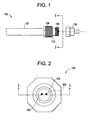
- FIG. 1 is a front view of an exemplary embodiment of a heat detector.
- FIG. 2 is a side view along the line 2-2 of the heat detector of FIG. 1 .
- FIG. 3 is a partially cutaway front view of the heat detector along the line 3-3 of FIG. 2 .
- FIG. 4 is a front view of an alternate exemplary embodiment of a heat detector.
- Heat detectors are used in a number of industrial applications, to detect fires, trigger alarms and control the release of extinguishing agents. Installation and servicing heat detectors is difficult and time consuming in many applications since access to the electrical connectors may be limited.
- FIG. 1 illustrates a front view of an exemplary embodiment of a heat detector 100.
- the heat detector 100 includes housing member 102, a connector portion 104, and a line connector portion 108.
- the heat detector 100 may include a mount portion 106. In operation, the mount portion 106 may be used to mount the heat detector 100 in a desired location.
- FIG. 2 illustrates a side view of the heat detector 100 along the line 2-2 (of FIG. 1).
- FIG. 2 includes contacts 202 disposed in the connector portion 104.
- FIG. 3 illustrates a partially cut away front view of the heat detector 100 along the line 3-3 (of FIG. 2 ).
- FIG. 3 includes a sensor member 302 disposed in the housing member 102.
- the sensor member 302 may be hermetically sealed inside the housing member 102.
- the sensor member 302 is connected to the contacts 202 with conductors 304.
- the conductors 304 may include a number of types of conductive materials including, for example, copper wire or other similar materials.
- the housing member 102 may be formed from number of materials such as, for example stainless steel, steel, or other alloys.
- the sensor member 302 closes internal contacts (not shown) that complete a circuit that includes the conductors 304 and the contacts 202.
- the contacts 202 are electrically connected to a sensing circuit (not shown) that detects the closed circuit and may direct an appropriate action, such as, for example sending an alarm signal and triggering an extinguishing system.
- the illustrated embodiment includes a connector portion 104 having male threads.
- a line connector portion 108 is shown that includes female threads and female contacts 306 and conductors 308.
- the line connector portion 108 mechanically engages the connector portion 104, hermetically sealing the contacts 202 and 306.
- the contacts 202 engage the contacts 306 making an electrical connection.
- Alternate embodiments may include a connector portion 104 having female threads and a line connector portion 108 having male threads.
- the contacts 202 may be female, while the corresponding contacts 306 are male.
- the embodiments are not limited to two contacts 202 and 306, but may include any number of contacts and corresponding conductors according to the specifications of the heat detector 100 and systems including the heat detector 100.
- FIG. 4 illustrates a front view of an alternate embodiment of the heat detector 400.
- the heat detector 400 includes a connector portion 104 having pins 402 that engage slots 404 in the line connector portion 108 securing a mechanical connection between the connector portion 104 and the line connector portion 108.
- the connector portion 104 may be attached to the housing member 102 with a weld, a braze, fasteners such as, for example, machine screws, a crimp, or a press fit in the shaded region 110 (of FIG. 1 ).
- the housing member 102 may include a threaded connector portion 104 that is fabricated by, for example, a machining a blank material to form both the housing member 102 and the connector portion 104.
- the use of the connector portion 104 allows the line connector portion 108 to be easily attached and unattached without using tools.
- the use of the illustrated connectors decreases the labor costs of using tools to connect the heat detector 100 to a monitoring system.
Landscapes
- Physics & Mathematics (AREA)
- General Physics & Mathematics (AREA)
- Fire-Detection Mechanisms (AREA)
- Fire Alarms (AREA)
- Geophysics And Detection Of Objects (AREA)
Abstract
Description
- The subject matter disclosed herein relates to heat detectors and particularly to heat detector connectors.
- Heat detectors may be used in a variety of applications including, for example, engine enclosures, industrial spaces, and high value locations and are often used to detect fires. When a heat detector is serviced or replaced, a technician often disconnects and reconnects wires from connection terminals on the heat detector. The connection terminals on the heat detector are difficult and time consuming to manipulate. An improved heat detector is desired.
- According to one aspect of the invention, a heat detector comprising, a housing member, a first hermetic connector portion connected to the housing member, a sensor member disposed in the housing member operative to detect a temperature, and a first contact portion disposed in the first hermetic connector portion, wherein the contact portion is connected to the sensor member.
- According to another aspect of the invention, a method of fabricating a heat detector comprising, fabricating a housing member, disposing a sensor member in the housing member operative to detect a temperature, connecting a first hermetic connector portion to the housing member, and connecting a first contact portion in the first hermetic connector portion to the sensor member.
- These and other advantages and features will become more apparent from the following description taken in conjunction with the drawings.
- The subject matter, which is regarded as the invention, is particularly pointed out and distinctly claimed in the claims at the conclusion of the specification. The foregoing and other features, and advantages of the invention are apparent from the following detailed description taken in conjunction with the accompanying drawings in which:
-
FIG. 1 is a front view of an exemplary embodiment of a heat detector. -
FIG. 2 is a side view along the line 2-2 of the heat detector ofFIG. 1 . -
FIG. 3 is a partially cutaway front view of the heat detector along the line 3-3 ofFIG. 2 . -
FIG. 4 is a front view of an alternate exemplary embodiment of a heat detector. - The detailed description explains embodiments of the invention, together with advantages and features, by way of example with reference to the drawings.
- Heat detectors are used in a number of industrial applications, to detect fires, trigger alarms and control the release of extinguishing agents. Installation and servicing heat detectors is difficult and time consuming in many applications since access to the electrical connectors may be limited.
-
FIG. 1 illustrates a front view of an exemplary embodiment of aheat detector 100. Theheat detector 100 includeshousing member 102, aconnector portion 104, and aline connector portion 108. Theheat detector 100 may include amount portion 106. In operation, themount portion 106 may be used to mount theheat detector 100 in a desired location. -
FIG. 2 illustrates a side view of theheat detector 100 along the line 2-2 (ofFIG. 1). FIG. 2 includescontacts 202 disposed in theconnector portion 104. -
FIG. 3 illustrates a partially cut away front view of theheat detector 100 along the line 3-3 (ofFIG. 2 ).FIG. 3 includes asensor member 302 disposed in thehousing member 102. Thesensor member 302 may be hermetically sealed inside thehousing member 102. Thesensor member 302 is connected to thecontacts 202 withconductors 304. Theconductors 304 may include a number of types of conductive materials including, for example, copper wire or other similar materials. Thehousing member 102 may be formed from number of materials such as, for example stainless steel, steel, or other alloys. - In an example of operation, when, for example, a fire or other event heats the
housing member 102, thesensor member 302 closes internal contacts (not shown) that complete a circuit that includes theconductors 304 and thecontacts 202. Thecontacts 202 are electrically connected to a sensing circuit (not shown) that detects the closed circuit and may direct an appropriate action, such as, for example sending an alarm signal and triggering an extinguishing system. - Referring to
FIG. 3 , the illustrated embodiment includes aconnector portion 104 having male threads. Aline connector portion 108 is shown that includes female threads andfemale contacts 306 andconductors 308. Theline connector portion 108 mechanically engages theconnector portion 104, hermetically sealing thecontacts contacts 202 engage thecontacts 306 making an electrical connection. Alternate embodiments may include aconnector portion 104 having female threads and aline connector portion 108 having male threads. Thecontacts 202 may be female, while thecorresponding contacts 306 are male. The embodiments are not limited to twocontacts heat detector 100 and systems including theheat detector 100. -
FIG. 4 illustrates a front view of an alternate embodiment of theheat detector 400. Theheat detector 400 includes aconnector portion 104 havingpins 402 that engageslots 404 in theline connector portion 108 securing a mechanical connection between theconnector portion 104 and theline connector portion 108. - The
connector portion 104 may be attached to thehousing member 102 with a weld, a braze, fasteners such as, for example, machine screws, a crimp, or a press fit in the shaded region 110 (ofFIG. 1 ). Alternatively, thehousing member 102 may include a threadedconnector portion 104 that is fabricated by, for example, a machining a blank material to form both thehousing member 102 and theconnector portion 104. - The use of the
connector portion 104 allows theline connector portion 108 to be easily attached and unattached without using tools. The use of the illustrated connectors decreases the labor costs of using tools to connect theheat detector 100 to a monitoring system. - While the invention has been described in detail in connection with only a limited number of embodiments, it should be readily understood that the invention is not limited to such disclosed embodiments. Rather, the invention can be modified to incorporate any number of variations, alterations, substitutions or equivalent arrangements not heretofore described, but which are commensurate with the spirit and scope of the invention. Additionally, while various embodiments of the invention have been described, it is to be understood that aspects of the invention may include only some of the described embodiments. Accordingly, the invention is not to be seen as limited by the foregoing description, but is only limited by the scope of the appended claims.
- Aspects of the present invention are defined in the following numbered clauses:
- 1. A heat detector comprising:
- a housing member;
- a first hermetic connector portion connected to the housing member;
- a sensor member disposed in the housing member operative to detect a temperature; and
- a first contact portion disposed in the first hermetic connector portion, wherein the first contact portion is connected to the sensor member.
- 2. The heat detector of clause 1, wherein the heat detector further comprises a second connector portion having a second contact portion operative to engage the first hermetic connector portion.
- 3. The heat detector of clause 1 or
clause 2, wherein the first hermetic connector portion includes a threaded portion. - 4. The heat detector of
clause 2, wherein the second connector portion includes a threaded portion. - 5. The heat detector of any one of the preceding clauses, wherein the first hermetic connector portion includes a pin operative to engage a slot.
- 6. The heat detector of
clause 2, wherein the second connector portion includes a slot operative to engage a pin of the first hermetic connector portion. - 7. The heat detector of
clause 2, wherein the second contact portion is electrically connected to wire conductors. - 8. The heat detector of any one of the preceding clauses, wherein the housing member is operative to maintain a hermetic seal.
- 9. The heat detector of any one of the preceding clauses, wherein the heat detector further includes a weld operative to connect the first hermetic connector portion to the housing member.
- 10. The heat detector of any one of the preceding clauses, wherein the heat detector further includes a braze operative to connect the first hermetic connector portion to the housing member.
- 11. The heat detector of any one of the preceding clauses, wherein the heat detector further includes a fastener operative to connect the first hermetic connector portion to the housing member.
- 12. The heat detector of any one of the preceding clauses, wherein the heat detector further includes a press fitting operative to connect the first hermetic connector portion to the housing member.
- 13. A method of fabricating a heat detector comprising:
- fabricating a housing member;
- disposing a sensor member in the housing member operative to detect a temperature;
- connecting a first hermetic connector portion to the housing member; and
- connecting a first contact portion in the first hermetic connector portion to the sensor member.
- 14. The method of clause 13, wherein the first hermetic connector portion is connected to the housing member with a weld.
- 15. The method of clause 13 or clause 14, wherein the first hermetic connector portion is connected to the housing member with a braze.
- 16. The method of any one of clauses 13 to 15, wherein the first hermetic connector portion is connected to the housing member with a press fit.
- 17. The method of any one of clauses 13 to 16, wherein the first hermetic connector portion is connected to the housing member with a fastener.
- 18. The method of any one of clauses 13 to 17, wherein the first hermetic connector portion is connected to the housing member with a crimp.
Claims (15)
- A heat detector (100) comprising:a housing member (102);a first hermetic connector portion (104) connected to the housing member (102);a sensor member (302) disposed in the housing member (102) operative to detect a temperature; anda first contact portion (202) disposed in the first hermetic connector portion (104), wherein the first contact portion (202) is connected to the sensor member (302).
- The heat detector of claim 1, wherein the heat detector (100) further comprises a second connector portion (108) having a second contact portion (202) operative to engage the first hermetic connector portion (104).
- The heat detector of claim 1 or claim 2, wherein the first hermetic connector (104) portion includes a threaded portion.
- The heat detector of claim 2, wherein the second connector portion (108) includes a threaded portion.
- The heat detector of any one of the preceding claims, wherein the first hermetic connector portion (104) includes a pin (402) operative to engage a slot (404).
- The heat detector of claim 2, wherein the second connector pontion(108) includes a slot (404) operative to engage a pin (402) of the first hermetic connector portion (104).
- The heat detector of claim 2, wherein the second contact portion (202) is electrically connected to wire conductors (308).
- The heat detector of any one of the preceding claims, wherein the housing member (102) is operative to maintain a hermetic seal.
- The heat detector of any one of the preceding claims, wherein the heat detector further includes a weld operative to connect the first hermetic connector portion (104) to the housing member (102).
- The heat detector of any one of the preceding claims, wherein the heat detector further includes a braze operative to connect the first hermetic connector portion (104) to the housing member (102).
- A method of fabricating a heat detector comprising:fabricating a housing member;disposing a sensor member in the housing member operative to detect a temperature;connecting a first hermetic connector portion to the housing member; andconnecting a first contact portion in the first hermetic connector portion to the sensor member.
- The method of claim 11 wherein the first hermetic connector portion is connected to the housing member with a weld.
- The method of claim 11 or claim 12, wherein the first hermetic connector portion is connected to the housing member with a braze.
- The method of any one of claims 11 to 13, wherein the first hermetic connector portion is connected to the housing member with a press fit.
- The method of any one of claims 11 to 14, wherein the first hermetic connector portion is connected to the housing member with a fastener.
Applications Claiming Priority (1)
| Application Number | Priority Date | Filing Date | Title |
|---|---|---|---|
| US12/405,648 US20100238973A1 (en) | 2009-03-17 | 2009-03-17 | Methods and apparatus involving heat detectors |
Publications (2)
| Publication Number | Publication Date |
|---|---|
| EP2230498A2 true EP2230498A2 (en) | 2010-09-22 |
| EP2230498A3 EP2230498A3 (en) | 2014-07-09 |
Family
ID=42289161
Family Applications (1)
| Application Number | Title | Priority Date | Filing Date |
|---|---|---|---|
| EP10156378.1A Withdrawn EP2230498A3 (en) | 2009-03-17 | 2010-03-12 | Methods and apparatus involving heat detectors |
Country Status (4)
| Country | Link |
|---|---|
| US (1) | US20100238973A1 (en) |
| EP (1) | EP2230498A3 (en) |
| JP (1) | JP2010217177A (en) |
| CN (1) | CN101881805A (en) |
Families Citing this family (5)
| Publication number | Priority date | Publication date | Assignee | Title |
|---|---|---|---|---|
| KR101277773B1 (en) * | 2012-12-28 | 2013-06-24 | 우진 일렉트로나이트(주) | Replacement device for holder and holder assembly |
| USD756810S1 (en) | 2014-09-09 | 2016-05-24 | Yerriswamy Pateel | Temperature indicating crayon holder with hexagon collet |
| CN105486419A (en) * | 2014-09-19 | 2016-04-13 | 富泰华工业(深圳)有限公司 | Temperature sensor |
| WO2020128799A2 (en) | 2018-12-17 | 2020-06-25 | Tyco Fire Products Lp | Fire detection and suppression system with high temperature connector |
| USD1077657S1 (en) * | 2022-10-28 | 2025-06-03 | Sreedhara Gowd Patil | Temperature indicating crayon holder |
Family Cites Families (20)
| Publication number | Priority date | Publication date | Assignee | Title |
|---|---|---|---|---|
| US1675210A (en) * | 1926-10-29 | 1928-06-26 | Leo F Campbell | Thermometer well |
| US2698926A (en) * | 1951-12-07 | 1955-01-04 | Sun Oil Co | Cable connector |
| JPS53132382U (en) * | 1977-03-28 | 1978-10-20 | ||
| US4708663A (en) * | 1986-04-21 | 1987-11-24 | Woodhead Industries, Inc. | Rotatable electrical elbow fitting |
| US5022865A (en) * | 1988-09-14 | 1991-06-11 | Simmonds Precision Products, Inc. | Hermetically sealing connector and method of use thereof |
| US5046857A (en) * | 1990-05-23 | 1991-09-10 | General Motors Corporation | Plastic thermal probe assembly with press fit sensor |
| US5110307B1 (en) * | 1991-07-09 | 1994-09-20 | Balo Precision Parts Inc | Laser weldable hermetic connector |
| JP2914088B2 (en) * | 1993-04-16 | 1999-06-28 | 住友電装株式会社 | Connector with rotation guide |
| JP2929261B2 (en) * | 1994-06-07 | 1999-08-03 | 中部助川興業株式会社 | Temperature sensor |
| US5749656A (en) * | 1995-08-11 | 1998-05-12 | General Motors Corporation | Thermal probe assembly with mold-over crimp sensor packaging |
| JP2933581B1 (en) * | 1998-02-04 | 1999-08-16 | 株式会社岡崎製作所 | Temperature measurement probe |
| JP2000186961A (en) * | 1998-12-24 | 2000-07-04 | Nkk Corp | Tip guide device for optical fiber and method for measuring temperature of molten metal |
| US6100470A (en) * | 1999-02-26 | 2000-08-08 | Arlington Industries, Inc. | Separatable snap in connectors for pre-connectorized cable |
| US6588931B2 (en) * | 2000-12-07 | 2003-07-08 | Delphi Technologies, Inc. | Temperature sensor with flexible circuit substrate |
| DE10109828A1 (en) * | 2001-03-01 | 2002-09-05 | Xcellsis Gmbh | Electrical temperature measuring device used for measuring the temperature inside thermally insulated gas generating box comprises temperature sensor arranged in protective tube with metal screw fixed to tube |
| DE20106011U1 (en) * | 2001-04-05 | 2001-08-09 | Mesure Technology Co., Ltd., San Chung, Taipeh | Thermometer with interchangeable measuring heads |
| JP3956809B2 (en) * | 2002-09-09 | 2007-08-08 | 株式会社デンソー | Pressure sensor |
| JP2006029967A (en) * | 2004-07-15 | 2006-02-02 | Denso Corp | Sensor and manufacturing method thereof |
| DE102006024967B4 (en) * | 2006-05-29 | 2010-09-16 | Asm Automation Sensorik Messtechnik Gmbh | Waterproof sensor |
| JP2008215846A (en) * | 2007-02-28 | 2008-09-18 | Denso Corp | Temperature sensor mounting structure |
-
2009
- 2009-03-17 US US12/405,648 patent/US20100238973A1/en not_active Abandoned
-
2010
- 2010-03-12 JP JP2010055243A patent/JP2010217177A/en not_active Withdrawn
- 2010-03-12 EP EP10156378.1A patent/EP2230498A3/en not_active Withdrawn
- 2010-03-17 CN CN2010101571897A patent/CN101881805A/en active Pending
Non-Patent Citations (1)
| Title |
|---|
| None |
Also Published As
| Publication number | Publication date |
|---|---|
| JP2010217177A (en) | 2010-09-30 |
| EP2230498A3 (en) | 2014-07-09 |
| US20100238973A1 (en) | 2010-09-23 |
| CN101881805A (en) | 2010-11-10 |
Similar Documents
| Publication | Publication Date | Title |
|---|---|---|
| EP2230498A2 (en) | Methods and apparatus involving heat detectors | |
| CN103682854A (en) | Power cord | |
| US7938693B2 (en) | PE connection for plug connectors | |
| US20040264544A1 (en) | Sensor and sensor assembly | |
| CN106654765B (en) | Electrical plug connector for safety restraint system | |
| KR20220097359A (en) | Sensor device having crimped housing and method for assembling the same | |
| CN103682882A (en) | Connector connecting structure | |
| EP4002605A1 (en) | Electrical connection structure | |
| JP2727367B2 (en) | connector | |
| EP2702635B1 (en) | Connector assembly for establishing an electrical connection with wires | |
| JP4808674B2 (en) | SPD for power supply | |
| CN212845592U (en) | Power detector, power theft prevention device, power monitoring device, and air switch | |
| EP3487014A1 (en) | Electric arcing protection arrangement and method | |
| CN212623012U (en) | Real-time online detection copper bar wiring device based on Internet of things | |
| JP2012257343A (en) | Distribution board including overheat detector | |
| JP7361550B2 (en) | connector | |
| EP3671796A1 (en) | Projectile assembly and electrical circuit interrupting device | |
| CN213457305U (en) | Current detector and detection device | |
| JP6329748B2 (en) | Electrical connector | |
| EP3128613A1 (en) | Electrical terminal | |
| JP7692316B2 (en) | Electrical connection abnormality detection sensor and power outlet | |
| KR102920511B1 (en) | Outlet Plug-type outlet Electrical safety diagnosis and fire prevention device | |
| CN223093247U (en) | Plug with over-temperature protection | |
| JP2024507123A (en) | Systems and methods for electrical connector housings and sealed circuit boards | |
| JP2025007056A (en) | Extension cord set |
Legal Events
| Date | Code | Title | Description |
|---|---|---|---|
| PUAI | Public reference made under article 153(3) epc to a published international application that has entered the european phase |
Free format text: ORIGINAL CODE: 0009012 |
|
| AK | Designated contracting states |
Kind code of ref document: A2 Designated state(s): AT BE BG CH CY CZ DE DK EE ES FI FR GB GR HR HU IE IS IT LI LT LU LV MC MK MT NL NO PL PT RO SE SI SK SM TR |
|
| AX | Request for extension of the european patent |
Extension state: AL BA ME RS |
|
| PUAL | Search report despatched |
Free format text: ORIGINAL CODE: 0009013 |
|
| AK | Designated contracting states |
Kind code of ref document: A3 Designated state(s): AT BE BG CH CY CZ DE DK EE ES FI FR GB GR HR HU IE IS IT LI LT LU LV MC MK MT NL NO PL PT RO SE SI SK SM TR |
|
| AX | Request for extension of the european patent |
Extension state: AL BA ME RS |
|
| RIC1 | Information provided on ipc code assigned before grant |
Ipc: G01K 1/14 20060101ALI20140605BHEP Ipc: G01K 1/08 20060101AFI20140605BHEP |
|
| STAA | Information on the status of an ep patent application or granted ep patent |
Free format text: STATUS: THE APPLICATION IS DEEMED TO BE WITHDRAWN |
|
| 18D | Application deemed to be withdrawn |
Effective date: 20141001 |