EP2230459A1 - Combustor of gas turbine - Google Patents
Combustor of gas turbine Download PDFInfo
- Publication number
- EP2230459A1 EP2230459A1 EP08868158A EP08868158A EP2230459A1 EP 2230459 A1 EP2230459 A1 EP 2230459A1 EP 08868158 A EP08868158 A EP 08868158A EP 08868158 A EP08868158 A EP 08868158A EP 2230459 A1 EP2230459 A1 EP 2230459A1
- Authority
- EP
- European Patent Office
- Prior art keywords
- premixed gas
- gas generator
- combustor
- combustion flame
- wall surface
- Prior art date
- Legal status (The legal status is an assumption and is not a legal conclusion. Google has not performed a legal analysis and makes no representation as to the accuracy of the status listed.)
- Granted
Links
Images




Classifications
-
- F—MECHANICAL ENGINEERING; LIGHTING; HEATING; WEAPONS; BLASTING
- F23—COMBUSTION APPARATUS; COMBUSTION PROCESSES
- F23R—GENERATING COMBUSTION PRODUCTS OF HIGH PRESSURE OR HIGH VELOCITY, e.g. GAS-TURBINE COMBUSTION CHAMBERS
- F23R3/00—Continuous combustion chambers using liquid or gaseous fuel
- F23R3/28—Continuous combustion chambers using liquid or gaseous fuel characterised by the fuel supply
- F23R3/286—Continuous combustion chambers using liquid or gaseous fuel characterised by the fuel supply having fuel-air premixing devices
-
- F—MECHANICAL ENGINEERING; LIGHTING; HEATING; WEAPONS; BLASTING
- F02—COMBUSTION ENGINES; HOT-GAS OR COMBUSTION-PRODUCT ENGINE PLANTS
- F02C—GAS-TURBINE PLANTS; AIR INTAKES FOR JET-PROPULSION PLANTS; CONTROLLING FUEL SUPPLY IN AIR-BREATHING JET-PROPULSION PLANTS
- F02C7/00—Features, components parts, details or accessories, not provided for in, or of interest apart form groups F02C1/00 - F02C6/00; Air intakes for jet-propulsion plants
- F02C7/22—Fuel supply systems
- F02C7/228—Dividing fuel between various burners
-
- F—MECHANICAL ENGINEERING; LIGHTING; HEATING; WEAPONS; BLASTING
- F23—COMBUSTION APPARATUS; COMBUSTION PROCESSES
- F23R—GENERATING COMBUSTION PRODUCTS OF HIGH PRESSURE OR HIGH VELOCITY, e.g. GAS-TURBINE COMBUSTION CHAMBERS
- F23R3/00—Continuous combustion chambers using liquid or gaseous fuel
- F23R3/28—Continuous combustion chambers using liquid or gaseous fuel characterised by the fuel supply
- F23R3/30—Continuous combustion chambers using liquid or gaseous fuel characterised by the fuel supply comprising fuel prevapourising devices
- F23R3/32—Continuous combustion chambers using liquid or gaseous fuel characterised by the fuel supply comprising fuel prevapourising devices being tubular
-
- F—MECHANICAL ENGINEERING; LIGHTING; HEATING; WEAPONS; BLASTING
- F23—COMBUSTION APPARATUS; COMBUSTION PROCESSES
- F23R—GENERATING COMBUSTION PRODUCTS OF HIGH PRESSURE OR HIGH VELOCITY, e.g. GAS-TURBINE COMBUSTION CHAMBERS
- F23R3/00—Continuous combustion chambers using liquid or gaseous fuel
- F23R3/28—Continuous combustion chambers using liquid or gaseous fuel characterised by the fuel supply
- F23R3/34—Feeding into different combustion zones
- F23R3/346—Feeding into different combustion zones for staged combustion
-
- F—MECHANICAL ENGINEERING; LIGHTING; HEATING; WEAPONS; BLASTING
- F23—COMBUSTION APPARATUS; COMBUSTION PROCESSES
- F23R—GENERATING COMBUSTION PRODUCTS OF HIGH PRESSURE OR HIGH VELOCITY, e.g. GAS-TURBINE COMBUSTION CHAMBERS
- F23R3/00—Continuous combustion chambers using liquid or gaseous fuel
- F23R3/42—Continuous combustion chambers using liquid or gaseous fuel characterised by the arrangement or form of the flame tubes or combustion chambers
- F23R3/46—Combustion chambers comprising an annular arrangement of several essentially tubular flame tubes within a common annular casing or within individual casings
-
- F—MECHANICAL ENGINEERING; LIGHTING; HEATING; WEAPONS; BLASTING
- F23—COMBUSTION APPARATUS; COMBUSTION PROCESSES
- F23R—GENERATING COMBUSTION PRODUCTS OF HIGH PRESSURE OR HIGH VELOCITY, e.g. GAS-TURBINE COMBUSTION CHAMBERS
- F23R3/00—Continuous combustion chambers using liquid or gaseous fuel
- F23R3/42—Continuous combustion chambers using liquid or gaseous fuel characterised by the arrangement or form of the flame tubes or combustion chambers
- F23R3/54—Reverse-flow combustion chambers
-
- F—MECHANICAL ENGINEERING; LIGHTING; HEATING; WEAPONS; BLASTING
- F05—INDEXING SCHEMES RELATING TO ENGINES OR PUMPS IN VARIOUS SUBCLASSES OF CLASSES F01-F04
- F05D—INDEXING SCHEME FOR ASPECTS RELATING TO NON-POSITIVE-DISPLACEMENT MACHINES OR ENGINES, GAS-TURBINES OR JET-PROPULSION PLANTS
- F05D2260/00—Function
- F05D2260/14—Preswirling
-
- F—MECHANICAL ENGINEERING; LIGHTING; HEATING; WEAPONS; BLASTING
- F23—COMBUSTION APPARATUS; COMBUSTION PROCESSES
- F23R—GENERATING COMBUSTION PRODUCTS OF HIGH PRESSURE OR HIGH VELOCITY, e.g. GAS-TURBINE COMBUSTION CHAMBERS
- F23R2900/00—Special features of, or arrangements for continuous combustion chambers; Combustion processes therefor
- F23R2900/00014—Reducing thermo-acoustic vibrations by passive means, e.g. by Helmholtz resonators
Definitions
- the present invention relates to a combustor of a gas turbine, and, more particularly to a combustor of a gas turbine capable of suppressing generation of combustion oscillation.
- a typical combustor of a gas turbine includes an premixed gas generator (swirler) that produces combustion flame, an inner cylinder that has therein the premixed gas generator, and a transition piece that connects the inner cylinder to an inlet of a turbine.
- premixed gas generator spark generator
- inner cylinder that has therein the premixed gas generator
- transition piece that connects the inner cylinder to an inlet of a turbine.
- a combustor of a gas turbine having this configuration is known as a conventional technique and disclosed in Patent Document 1.
- an inner cylinder is connected to a transition piece.
- An inner swirler and an outer swirler are placed within the inner cylinder.
- the inner swirler includes: a cylindrical inner swirler ring arranged concentrically about a central axis of the inner cylinder; and a plurality of inner swirler vanes provided on an outer circumferential surface of the inner swirler ring.
- the outer swirler includes: a cylindrical outer swirler ring arranged on an outer circumferential side of the inner swirler vanes and concentrically with the inner swirler ring; and a plurality of outer swirler vanes provided on an outer circumferential surface of the outer swirler ring.
- Patent Document 1 Japanese Patent Application Laid-open No. 2006-300448
- the conventional combustor of the gas turbine has an issue of suppressing generation of combustion oscillation caused by concentrated heat generation.
- An object of the present invention is to provide a combustor of a gas turbine capable of suppressing generation of combustion oscillation.
- a combustor of a gas turbine includes: an premixed gas generator that produces combustion flame; an inner cylinder that has therein the premixed gas generator; and a transition piece that connects the inner cylinder to an inlet of a turbine.
- a premixed gas generator outlet of the premixed gas generator has an inner wall surface, and a part of the inner wall surface, located outward in a radial direction of the combustor, is extended further in an axial direction of the combustion flame than a part of the inner wall surface, located inward in the radial direction of the combustor.
- the part of the inner wall surface of the premixed gas generator outlet of the premixed gas generator, located outward in the radial direction of the combustor, is extended further in the axial direction of the combustion flame than the radially-inward part of the inner wall surface.
- the combustion flame extends from the premixed gas generator smoothly along the extended radially-outward part of the inner wall surface.
- the combustion flame is dispersed in the axial direction of the transition piece 32, so that the combustion flame is stabilized. This provides an advantage of suppressing generation of combustion oscillation.
- the combustor has at least a pair of the premixed gas generators including an inner premixed gas generator and an outer premixed gas generator, the inner premixed gas generator is placed inward of the outer premixed gas generator in the radial direction of the combustor, and an premixed gas generator outlet of the inner premixed gas generator is located upstream of an premixed gas generator outlet of the outer premixed gas generator in the axial direction of the combustor.
- the premixed gas generator outlet of the inner premixed gas generator and the premixed gas generator outlet of the outer premixed gas generator are placed at different positions from each other in the axial direction of the combustor. Consequently, a total length of the combustion flame increases. This causes the combustion flame to generate heat at distributed positions, and thus provides an advantage of suppressing generation of combustion oscillation. For example, if the premixed gas generator outlet of the inner premixed gas generator and the premixed gas generator outlet of the outer premixed gas generator are at the same position in the axial direction of the combustor, the combustion flame causes concentrated heat generation, and thus combustion oscillation tend to be generated.
- a distance L between the outer premixed gas generator and the inlet of the turbine and a distance L1 between the premixed gas generator outlet of the inner premixed gas generator and the premixed gas generator outlet of the outer premixed gas generator have a relationship expressed as 0.2 ⁇ L1/L.
- the distance L1 between the premixed gas generator outlet of the inner premixed gas generator and the premixed gas generator outlet of the outer premixed gas generator is predetermined appropriately. This causes heat generated by the combustion flame to be effectively dispersed, and thus provides an advantage of suppressing generation of combustion oscillation.
- the part of the inner wall surface of the premixed gas generator outlet of the premixed gas generator, located outward in the radial direction of the combustor, has a diameter that increases in a stepped manner at a location of a distal end of the combustion flame.
- a step is provided at a location of the distal end of the combustion flame, so that a position of the distal end of the combustion flame is clarified. According to this configuration, a combustion gas circulation area is created at the distal end of the combustion flame. This provides an advantage of stabilizing the combustion flame.
- the part of the inner wall surface of the premixed gas generator outlet of the premixed gas generator, located outward in the radial direction of the combustor, has a decreasing diameter.
- the inner wall surface with the decreasing diameter results in an increase in a moving speed of the combustion flame (flame surface), which produces longer combustion flame. This causes the combustion flame to be distributed and stabilized in the axial direction of the transition piece, and thus provides an advantage of suppressing generation of combustion oscillation.
- a combustor of a gas turbine includes: a plurality of premixed gas generators that produce combustion flame; an inner cylinder that has therein the premixed gas generators; and a transition piece that connects the inner cylinder to an inlet of a turbine.
- An premixed gas generator outlet of at least one of the premixed gas generators is located upstream of premixed gas generator outlets of the other premixed gas generators in the axial direction of the combustor.
- the premixed gas generator outlet of at least one of the premixed gas generators is placed at a different position from the premixed gas generator outlets of the outer premixed gas generators in the axial direction of the combustor. Consequently, a total length of the combustion flame increases. This causes the combustion flame to generate heat at distributed positions, and thus provides an advantage of suppressing generation of combustion oscillation.
- a part of an inner wall surface of the premixed gas generator outlet of the premixed gas generator, which is located outward in a radial direction of the combustor, is extended further in an axial direction of the combustion flame than a part of the inner wall surface, which is located inward in the radial direction of the combustor.
- the combustion flame extends from the premixed gas generator smoothly along the extended radially-outward part of the inner wall surface.
- the combustion flame is dispersed in the axial direction of the transition piece 32, so that the combustion flame is stabilized. This provides an advantage of suppressing generation of combustion oscillation.
- Fig. 1 is a configuration diagram of a combustor of a gas turbine according to an embodiment of the present invention.
- Fig. 2 is an explanatory diagram of an operation of the combustor shown in Fig. 1 .
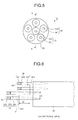
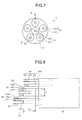
- Figs. 3 to 8 are explanatory diagrams of modifications of the combustor of the gas turbine shown in Fig. 1 .
- Fig. 9 is a configuration diagram of a general gas turbine.
- Fig. 10 is a configuration diagram of a combustor of the gas turbine shown in Fig. 9 .
- a gas turbine 1 has a compressor 2, a combustor 3, and a turbine 4 (see Fig. 9 ).
- the compressor 2 compresses air introduced from an air intake to produce compressed air.
- the combustor 3 sprays fuel into the compressed air to produce high-temperature, high-pressure combustion gas.
- the turbine 4 converts thermal energy of the combustion gas into rotational energy for a rotor 5 to cause the rotor 5 to produce a driving force.
- the driving force is transmitted to a generator (not shown) connected to the rotor 5.
- the combustor 3 is provided at the rear of an outlet of the compressor 2 and in front of an inlet of the turbine 4 (see Figs. 9 and 10 ).
- a plurality of the combustors 3 are annularly arranged in a circumferential direction of the turbine 4.
- Each of the combustors 3 has an inner cylinder 31, a transition piece 32, and premixed gas generators (swirlers) 33 and 34 (see Fig. 1 ).
- the inner cylinder 31 is a cylindrical member that defines a combustion chamber of the combustor 3.
- the inner cylinder 31 is provided fixedly to a casing 21 of the compressor 2.
- the transition piece 32 is a cylindrical member that connects the inner cylinder 31 to an inlet 41 of the turbine 4.
- the premixed gas generators 33 and 34 are placed within the inner cylinder 31 to produce combustion flame.
- air compressed by the compressor 2 is introduced into the inner cylinder 31 of the combustor 3, and is supplied to the premixed gas generators 33 and 34.
- the premixed gas generators 33 and 34 mix the compressed air with fuel to produce combustion flame.
- High-temperature and high-pressure combustion gas produced by the combustion flame is supplied to the turbine 4 through the transition piece 32.
- the premixed gas generator 33 (34) of the combustor 3 has a swirler vane 331 (341) and a fuel injector 332 (333) (see Fig. 1 ).
- the swirler vane 331 (341) is placed on a compressed air passage R1 (R2) to swirl the compressed air.
- the passage R1 (R2) is formed inside of the inner cylinder 31.
- the fuel injector 332 (333) is placed on the compressed air passage R1 (R2) and downstream of the swirler vane 331 (341) to spray fuel into the compressed air.
- the premixed gas generators 33 and 34 have a dual structure (double-swirler structure) (see Fig. 1 ).
- the combustor 3 has the inner premixed gas generator 33 and the outer premixed gas generator 34 inside of the inner cylinder 31.
- These premixed gas generators 33 and 34 both have an annular structure and are arranged concentrically about a central axis of the inner cylinder 31.
- the outer premixed gas generator 34 is placed outward of the inner premixed gas generator 33 in a radial direction of the inner cylinder 31 (surrounding an outer circumference of the inner premixed gas generator 33).
- the inner premixed gas generator 33 and the outer premixed gas generator 34 are placed with a cylindrical swirler ring 35 interposed therebetween.
- the premixed gas generator 33 In the premixed gas generator 33 (34), when the compressed air passes through the swirler vane 331 (341) on the passage R1 (R2), a swirling flow of the compressed air is formed (see Fig. 1 ).
- the fuel injector 332 (333) sprays fuel into the swirling flow to form air-fuel mixture.
- the air-fuel mixture is burnt, thus producing combustion flame.
- An amount of the fuel to be sprayed from the fuel injector 332 (333) is adjusted such that the combustion flame produced in the inner premixed gas generator 33 is in a fuel-rich condition (rich combustion flame), while the combustion flame produced in the outer premixed gas generator 34 is in a fuel-lean condition (lean flame).
- the rich combustion flame (combustion flame from the inner premixed gas generator 33) is formed in a central area of the transition piece 32, while the lean combustion flame (combustion flame from the outer premixed gas generator 34) is formed in an area near a wall surface of the transition piece 32.
- the rich combustion flame causes a flame surface temperature to decrease. This reduces an amount of NOx generated.
- a temperature of the fuel gas is low. This results in a small amount of NOx generated. Consequently, a total amount of NOx generated in the combustor 3 is reduced.
- the fuel injector 332 (342) is placed downstream of the swirler vane 331 (341). Such a configuration is preferable because a backfire of the combustion flame (particularly, lean combustion flame) is prevented.
- the present invention is not limited to this configuration, and the fuel injector 332 (342) can be placed upstream of the swirler vane 331 (341).
- a part of an inner wall surface of an premixed gas generator outlet 333 (343) of the premixed gas generator 33 (34), which is located outward in a radial direction of the combustor 3, is extended further in an axial direction of the combustion flame than a part of the inner wall surface, which is located inward in the radial direction of the combustor, to reduce combustion oscillation (see Fig. 1 ). More specifically, at the premixed gas generator outlet 333 (343) of the premixed gas generator 33 (44), the radially-outward part of the inner wall surface of the combustor 3 extends steplessly in the axial direction of the combustion flame (in the axial direction of the transition piece 32).
- the combustion flame exiting from the premixed gas generator outlet 333 extends smoothly along the extended radially-outward part of the inner wall surface.
- the combustion flame is then dispersed in the axial direction of the transition piece 32, so that the combustion flame is stabilized (see Fig. 2 ). This suppresses generation of combustion oscillation.
- a flame surface of the combustion flame is shown by broken lines.
- the compressed air passage R1 (R2) is formed in the inner cylinder 31, and the swirler vane 331 (341) is placed on the compressed air passage R1 (R2) (see Fig. 1 ).
- the fuel injector 332 (342) is formed on the compressed air passage R1 (R2) and downstream of the swirler vane 331 (341), thereby forming the premixed gas generator 33 (34).
- the inner premixed gas generator 33 has an annular structure with an premixed gas generator outlet 36 located at the center of the annular structure. More specifically, the premixed gas generator outlet 36 forms a part of a wall surface of the compressed air passage R1 of the inner premixed gas generator 33, located inward in the radial direction of the combustor 3.
- the inner premixed gas generator 33 and the outer premixed gas generator 34 are placed with the swirler ring 35 interposed therebetween. That is, an inner circumferential surface of the swirler ring 35 forms a part of the wall surface of the compressed air passage R1 of the inner premixed gas generator 33, located outward in the radial direction of the combustor 3.
- the combustion flame is held at an end of the premixed gas generator outlet 36 (at an end downstream of the air-fuel mixture). Therefore, the end of the premixed gas generator outlet 36 forms the premixed gas generator outlet 333 of the inner premixed gas generator 33.
- the inner circumferential surface of the swirler ring 35 extends downstream of the air-fuel mixture relative to the end of the premixed gas generator outlet 36.
- the part of the inner wall surface of the premixed gas generator outlet 333 of the inner premixed gas generator 33 located outward in the radial direction of the combustor 3, is extended further in the axial direction of the combustion flame than the radially-inward part of the inner wall surface.
- an outer circumferential surface of the swirler ring 35 forms a part of a wall surface of the compressed air passage R2 of the outer premixed gas generator 34, located inward in the radial direction of the combustor 3.
- An inner wall surface of the inner cylinder 31 (or an inner wall surface of the transition piece 32) forms a part of the wall surface of the compressed air passage R2 of the outer premixed gas generator 34, located outward in the radial direction of the combustor 3.
- the end of the swirler ring 35 forms the premixed gas generator outlet 343 of the outer premixed gas generator 34.
- the inner wall surface of the inner cylinder 31 (or the inner wall surface of the transition piece 32) extends downstream of the air-fuel mixture relative to the end of the swirler ring 35.
- the part of the inner wall surface of the premixed gas generator outlet 343 of the premixed gas generator 34, located outward in the radial direction of the combustor 3, is extended further in the axial direction of the combustion flame than the radially-inward part of the inner wall surface.
- the inner wall surface of the inner cylinder 31 is flush with the inner wall surface of the transition piece 32.
- the premixed gas generator outlet 333 of the inner premixed gas generator 33 is located upstream of the premixed gas generator outlet 343 of the outer premixed gas generator 34 in the axial direction of the combustor 3 (upstream in the flow direction of the combustion gas) (see Fig. 1 ). That is, in an axial sectional view of the combustor 3, the premixed gas generator outlet 333 of the inner premixed gas generator 33 is shifted upstream in the axial direction of the combustor 3 with respect to the outer premixed gas generator 34.
- the premixed gas generator outlet 333 of the inner premixed gas generator 33 and the premixed gas generator outlet 343 of the outer premixed gas generator 34 are placed at different positions from each other in the axial direction of the combustor 3. Consequently, the total length of the combustion flame increases. This causes the combustion flame to generate heat at distributed positions, and thus suppresses generation of combustion oscillation.
- the premixed gas generator outlet 333 of the inner premixed gas generator 33 is pulled down toward the upstream side in the axial direction of the combustor 3, and is placed at a deep position in the swirler ring 35 (see Fig. 1 ). Therefore, the premixed gas generator outlet 333 of the inner premixed gas generator 33 is located upstream of the premixed gas generator outlet 343 of the outer premixed gas generator 34 in the axial direction of the combustor 3.
- the part of the inner wall surface of the premixed gas generator outlet 333 (343) of the premixed gas generator 33 (34), located outward in the radial direction of the combustor 3, is extended further in the axial direction of the combustion flame than the radially-inward part of the inner wall surface (see Fig. 1 ).
- the combustion flame extends from the premixed gas generator 33 (34) smoothly along the extended radially-outward part of the inner wall surface.
- the combustion flame is dispersed in the axial direction of the transition piece 32, so that the combustion flame is stabilized (see Fig. 2 ). This provides an advantage of suppressing generation of combustion oscillation.
- the premixed gas generator outlet of the premixed gas generator is not extended further (if the radially-outward part and the radially-inward part of the inner wall surface of the combustor 3 are at the same position, and a step is created on the radially-outward part of the inner wall surface), the combustion flame is separated from the wall surface at the premixed gas generator outlet. Consequently, a flow rate of the combustion flame decreases. Thus, the combustion flame causes concentrated heat generation, and therefore combustion oscillation tends to be generated.
- the combustor 3 has a pair of the premixed gas generators 33 and 34, and the premixed gas generators 33 and 34 have a dual structure (a double swirler structure) (see Fig. 1 ).
- the present invention is not limited to this structure, and the premixed gas generator can have a single structure (not shown).
- the inner premixed gas generator 33 and the swirler ring 35 can be omitted, and thus only a single premixed gas generator (the outer premixed gas generator 34) can produce flame.
- the premixed gas generator outlet 333 of the inner premixed gas generator 33 is located upstream of the premixed gas generator outlet 343 of the outer premixed gas generator 34 in the axial direction of the combustor 3 (see Fig. 1 ).
- the premixed gas generator outlet 333 of the inner premixed gas generator 33 and the premixed gas generator outlet 343 of the outer premixed gas generator 34 are placed at different positions from each other in the axial direction of the combustor 3. Consequently, the total length of the combustion flame increases.
- the premixed gas generator outlet of the inner premixed gas generator and the premixed gas generator outlet of the outer premixed gas generator are at the same position in the axial direction of the combustor, the combustion flame causes concentrated heat generation, and thus combustion oscillation tends to be generated.
- a distance L between the outer premixed gas generator 34 and the inlet 41 of the turbine 4 (first-stage stator vanes of the turbine 4) and a distance L1 between the premixed gas generator outlet 333 of the inner premixed gas generator 33 and the premixed gas generator outlet 343 of the outer premixed gas generator 34 have a relationship expressed as 0.2 ⁇ L1/L (see Fig. 1 ).
- the distance L1 between the premixed gas generator outlet 333 of the inner premixed gas generator 33 and the premixed gas generator outlet 343 of the outer premixed gas generator 34 is predetermined appropriately. This causes heat generated by the combustion flame to be effectively dispersed, and thus provides an advantage of suppressing generation of combustion oscillation.
- an upper limit of a range of L1/L is defined according to a length of the combustion flame produced in the inner premixed gas generator 33.
- the distance L1 between the premixed gas generator outlet 333 of the inner premixed gas generator 33 and the premixed gas generator outlet 343 of the outer premixed gas generator 34 is defined such that a distal end of the combustion flame produced in the inner premixed gas generator 33 reaches a flame holding position for the combustion flame produced in the outer premixed gas generator 34 (the end of the swirler ring 35).
- an inner diameter of the transition piece 32 is predetermined to be substantially uniform in an area where the combustion flame produced in the premixed gas generators 33 and 34 extends (see Fig. 1 ). Such a configuration is preferable in view of facilitating design and manufacture of the transition piece 32.
- the present invention is not limited to this configuration.
- the part of the inner wall surface of the premixed gas generator outlet 333 (343) of the premixed gas generator 33 (34), located outward in the radial direction of the combustor 3 has an inner diameter that increases in a stepped manner at a location of the distal end of the combustion flame (see Fig. 3 ). That is, a step is provided at the location of the distal end of the combustion flame, so that the position of the distal end of the combustion flame is clarified. According to this configuration, a combustion gas circulation area is created at the distal end of the combustion flame, which advantageously stabilizes the combustion flame.
- the inner wall surface of the transition piece 32 linearly extends from the premixed gas generator outlet 343 of the outer premixed gas generator 34 in the axial direction of the transition piece 32, and has a diameter enlarged in a stepped manner at the location of the distal end of the combustion flame (see Fig. 3 ).
- a step 321 is provided at a position slightly upstream of a tip of the combustion flame, so that the wall surface of the transition piece 32 is widened in a stepped manner. Therefore, the combustion gas circulation area is created at the distal end of the combustion flame.
- the swirler ring 35 constitutes a similar step. That is, at the distal end of the combustion flame produced in the inner premixed gas generator 33, an edge of the swirler ring 35 is located and a combustion gas circulation area is created.
- the part of the inner wall surface of the premixed gas generator outlet 333 (343) of the premixed gas generator 33 (34), located outward in the radial direction of the combustor 3, has a decreasing inner diameter (see Fig. 4 ).
- the inner wall surface with the decreasing inner diameter results in an increase in moving speed of the combustion flame (flame surface), and thus results in longer combustion flame. This causes the combustion flame to be distributed and stabilized in the axial direction of the transition piece 32, and thus provides an advantage of suppressing generation of combustion oscillation.
- the combustion flame produced in the inner premixed gas generator 33 moves along the inner circumferential surface of the swirler ring 35 (see Fig. 4 ).
- An inner diameter of the swirler ring 35 gradually decreases, and thus an inner wall surface of the swirler ring 35 is formed into an inwardly narrowing shape.
- This configuration increases the moving speed of the combustion flame produced in the inner premixed gas generator 33.
- the combustion flame produced in the outer premixed gas generator 34 moves along the inner wall surface of the transition piece 32.
- An inner diameter of the transition piece 32 gradually decreases, and thus an inner wall surface of the transition piece 32 is formed into an inwardly narrowing shape. This configuration increases the moving speed of the combustion flame produced in the outer premixed gas generator 34.
- the inner diameter can start decreasing at any point.
- each inner diameter starts gradually decreasing at a longitudinally midway point of the combustion flame.
- the transition piece 32 can have a tapered shape or an envelope shape in the area where the combustion flame produced in the premixed gas generators 33 and 34 extends, thereby to moderately increase the inner diameter of the transition piece 32 toward the downstream side of the combustion flame (not shown).
- the inner wall surface of the transition piece 32 is inclined with respect to the central axis of the transition piece 32 preferably at an angle equal to or lower than 5 degrees, more preferably at an angle equal to or lower than 7 degrees, and furthermore preferably at an angle equal to or lower than 15 degrees. This ensures appropriate combustion of the combustion flame.
- the combustor 3 of the gas turbine having a plurality of premixed gas generators 33 and 34 can use a configuration in which an premixed gas generator outlet of at least one of the premixed gas generators is located upstream of premixed gas generator outlets of the other premixed gas generators in the axial direction of the combustor 3 (see Figs. 5 and 6 ).
- the premixed gas generator outlet 333 of the at least one premixed gas generator 33 is shifted in the axial direction of the combustor 3 with respect to the premixed gas generator outlets 343 of the outer premixed gas generators 34. Consequently, the total length of the combustion flame increases. This causes the combustion flame to generate heat at distributed positions, and thus provides an advantage of suppressing generation of combustion oscillation.
- the combustor 3 has a single unit of the inner premixed gas generator 33 and five units of the outer premixed gas generators 34 (see Fig. 5 ).
- the premixed gas generator 33 (34) includes the swirler vane 331 (341) and the fuel injector 332 (342) placed about the premixed gas generator outlet 334 (344).
- the inner premixed gas generator 33 is placed on the central axis of the combustor 3.
- the outer premixed gas generators 34 are placed around the inner premixed gas generator 33.
- the premixed gas generator outlet 333 of the inner premixed gas generator 33 is located upstream of the premixed gas generator outlets 343 of the remaining outer premixed gas generators 34 in the axial direction of the combustor 3 (see Fig. 6 ). This causes the combustion flame to generate heat at distributed positions.
- the premixed gas generator outlets 333 and 343 of the corresponding premixed gas generators 33 and 34 can be placed at different locations from each other in the axial direction of the combustor 3, respectively (see Figs. 7 and 8 ).
- the premixed gas generator outlets 333 (343) of the corresponding premixed gas generators 33 and 34 are placed in a more distributed manner in the axial direction of the combustor 3, compared to the modification configuration described above.
- the combustion flame generates heat at distributed positions. This suppresses generation of combustion oscillation effectively.
- a distance D1 (D2) between the premixed gas generator 34 located upstream in the axial direction of the combustor 3 and the premixed gas generator 33 (34) located downstream in the axial direction of the combustor 3 has a relationship relative to a diameter D of the premixed gas generator 33 (34), which is expressed as D1/D (D2/D). This ensures appropriate combustion of the combustion flame.
- the combustor of a gas turbine according to the present invention is useful for suppressing generation of combustion oscillation.
Landscapes
- Engineering & Computer Science (AREA)
- Chemical & Material Sciences (AREA)
- Combustion & Propulsion (AREA)
- Mechanical Engineering (AREA)
- General Engineering & Computer Science (AREA)
- Pre-Mixing And Non-Premixing Gas Burner (AREA)
Abstract
Description
- The present invention relates to a combustor of a gas turbine, and, more particularly to a combustor of a gas turbine capable of suppressing generation of combustion oscillation.
- A typical combustor of a gas turbine includes an premixed gas generator (swirler) that produces combustion flame, an inner cylinder that has therein the premixed gas generator, and a transition piece that connects the inner cylinder to an inlet of a turbine.
- A combustor of a gas turbine having this configuration is known as a conventional technique and disclosed in
Patent Document 1. In the conventional combustor of the gas turbine, an inner cylinder is connected to a transition piece. An inner swirler and an outer swirler are placed within the inner cylinder. The inner swirler includes: a cylindrical inner swirler ring arranged concentrically about a central axis of the inner cylinder; and a plurality of inner swirler vanes provided on an outer circumferential surface of the inner swirler ring. The outer swirler includes: a cylindrical outer swirler ring arranged on an outer circumferential side of the inner swirler vanes and concentrically with the inner swirler ring; and a plurality of outer swirler vanes provided on an outer circumferential surface of the outer swirler ring. - Patent Document 1: Japanese Patent Application Laid-open No.
2006-300448 - The conventional combustor of the gas turbine has an issue of suppressing generation of combustion oscillation caused by concentrated heat generation.
- An object of the present invention is to provide a combustor of a gas turbine capable of suppressing generation of combustion oscillation.
- According to an aspect of the present invention, a combustor of a gas turbine includes: an premixed gas generator that produces combustion flame; an inner cylinder that has therein the premixed gas generator; and a transition piece that connects the inner cylinder to an inlet of a turbine. A premixed gas generator outlet of the premixed gas generator has an inner wall surface, and a part of the inner wall surface, located outward in a radial direction of the combustor, is extended further in an axial direction of the combustion flame than a part of the inner wall surface, located inward in the radial direction of the combustor.
- In the combustor of the gas turbine, the part of the inner wall surface of the premixed gas generator outlet of the premixed gas generator, located outward in the radial direction of the combustor, is extended further in the axial direction of the combustion flame than the radially-inward part of the inner wall surface. According to this configuration, the combustion flame extends from the premixed gas generator smoothly along the extended radially-outward part of the inner wall surface. Thus, the combustion flame is dispersed in the axial direction of the
transition piece 32, so that the combustion flame is stabilized. This provides an advantage of suppressing generation of combustion oscillation. - Advantageously, in the combustor of a gas turbine, the combustor has at least a pair of the premixed gas generators including an inner premixed gas generator and an outer premixed gas generator, the inner premixed gas generator is placed inward of the outer premixed gas generator in the radial direction of the combustor, and an premixed gas generator outlet of the inner premixed gas generator is located upstream of an premixed gas generator outlet of the outer premixed gas generator in the axial direction of the combustor.
- In the combustor of the gas turbine, the premixed gas generator outlet of the inner premixed gas generator and the premixed gas generator outlet of the outer premixed gas generator are placed at different positions from each other in the axial direction of the combustor. Consequently, a total length of the combustion flame increases. This causes the combustion flame to generate heat at distributed positions, and thus provides an advantage of suppressing generation of combustion oscillation. For example, if the premixed gas generator outlet of the inner premixed gas generator and the premixed gas generator outlet of the outer premixed gas generator are at the same position in the axial direction of the combustor, the combustion flame causes concentrated heat generation, and thus combustion oscillation tend to be generated.
- Advantageously, in the combustor of a gas turbine, a distance L between the outer premixed gas generator and the inlet of the turbine and a distance L1 between the premixed gas generator outlet of the inner premixed gas generator and the premixed gas generator outlet of the outer premixed gas generator have a relationship expressed as 0.2≤L1/L.
- In the combustor of the gas turbine, the distance L1 between the premixed gas generator outlet of the inner premixed gas generator and the premixed gas generator outlet of the outer premixed gas generator is predetermined appropriately. This causes heat generated by the combustion flame to be effectively dispersed, and thus provides an advantage of suppressing generation of combustion oscillation.
- Advantageously, in the combustor of a gas turbine, the part of the inner wall surface of the premixed gas generator outlet of the premixed gas generator, located outward in the radial direction of the combustor, has a diameter that increases in a stepped manner at a location of a distal end of the combustion flame.
- In the combustor of the gas turbine, a step is provided at a location of the distal end of the combustion flame, so that a position of the distal end of the combustion flame is clarified. According to this configuration, a combustion gas circulation area is created at the distal end of the combustion flame. This provides an advantage of stabilizing the combustion flame.
- Advantageously, in the combustor of a gas turbine, the part of the inner wall surface of the premixed gas generator outlet of the premixed gas generator, located outward in the radial direction of the combustor, has a decreasing diameter.
- In the combustor of the gas turbine, the inner wall surface with the decreasing diameter results in an increase in a moving speed of the combustion flame (flame surface), which produces longer combustion flame. This causes the combustion flame to be distributed and stabilized in the axial direction of the transition piece, and thus provides an advantage of suppressing generation of combustion oscillation.
- According to another aspect of the present invention, a combustor of a gas turbine includes: a plurality of premixed gas generators that produce combustion flame; an inner cylinder that has therein the premixed gas generators; and a transition piece that connects the inner cylinder to an inlet of a turbine. An premixed gas generator outlet of at least one of the premixed gas generators is located upstream of premixed gas generator outlets of the other premixed gas generators in the axial direction of the combustor.
- In the combustor of the gas turbine, the premixed gas generator outlet of at least one of the premixed gas generators is placed at a different position from the premixed gas generator outlets of the outer premixed gas generators in the axial direction of the combustor. Consequently, a total length of the combustion flame increases. This causes the combustion flame to generate heat at distributed positions, and thus provides an advantage of suppressing generation of combustion oscillation.
- In the combustor of the gas turbine according to the present invention, a part of an inner wall surface of the premixed gas generator outlet of the premixed gas generator, which is located outward in a radial direction of the combustor, is extended further in an axial direction of the combustion flame than a part of the inner wall surface, which is located inward in the radial direction of the combustor. According to this configuration, the combustion flame extends from the premixed gas generator smoothly along the extended radially-outward part of the inner wall surface. Thus, the combustion flame is dispersed in the axial direction of the
transition piece 32, so that the combustion flame is stabilized. This provides an advantage of suppressing generation of combustion oscillation. -
- [
Fig. 1] Fig. 1 is a configuration diagram of a combustor of a gas turbine according to an embodiment of the present invention. - [
Fig. 2] Fig. 2 is an explanatory diagram of an operation of the combustor of the gas turbine shown inFig. 1 . - [
Fig. 3] Fig. 3 is an explanatory diagram of a modification of the combustor of the gas turbine shown inFig. 1 . - [
Fig. 4] Fig. 4 is an explanatory diagram of a modification of the combustor of the gas turbine shown inFig. 1 . - [
Fig. 5] Fig. 5 is an explanatory diagram of a modification of the combustor of the gas turbine shown inFig. 1 . - [
Fig. 6] Fig. 6 is an explanatory diagram of a modification of the combustor of the gas turbine shown inFig. 1 . - [
Fig. 7] Fig. 7 is an explanatory diagram of a modification of the combustor of the gas turbine shown inFig. 1 . - [
Fig. 8] Fig. 8 is an explanatory diagram of a modification of the combustor of the gas turbine shown inFig. 1 . - [
Fig. 9] Fig. 9 is a configuration diagram of a general gas turbine. - [
Fig. 10] Fig. 10 is a configuration diagram of a combustor of the gas turbine shown inFig. 9 . -
- 1
- gas turbine
- 2
- compressor
- 21
- casing
- 3
- combustor
- 31
- inner cylinder
- 32
- transition piece
- 321
- step
- 33
- inner premixed gas generator
- 331
- swirler vane
- 332
- fuel injector
- 333
- premixed gas generator outlet
- 334
- premixed gas generator outlet
- 34
- outer premixed gas generator
- 341
- swirler vane
- 342
- fuel injector
- 343
- premixed gas generator outlet
- 35
- swirler ring
- 36
- premixed gas generator outlet
- 4
- turbine
- 41
- inlet
- 5
- rotor
- The present invention will be explained in detail below with reference to the accompanying drawings. The invention is not limited to embodiments. The embodiments include constituent elements that are replaceable and can be obviously replaced while maintaining the identity of the invention. Modifications described in the embodiments can be arbitrarily combined within a range obvious to persons skilled in the art.
-
Fig. 1 is a configuration diagram of a combustor of a gas turbine according to an embodiment of the present invention.Fig. 2 is an explanatory diagram of an operation of the combustor shown inFig. 1 .Figs. 3 to 8 are explanatory diagrams of modifications of the combustor of the gas turbine shown inFig. 1 .Fig. 9 is a configuration diagram of a general gas turbine.Fig. 10 is a configuration diagram of a combustor of the gas turbine shown inFig. 9 . - A
gas turbine 1 has acompressor 2, acombustor 3, and a turbine 4 (seeFig. 9 ). Thecompressor 2 compresses air introduced from an air intake to produce compressed air. Thecombustor 3 sprays fuel into the compressed air to produce high-temperature, high-pressure combustion gas. Theturbine 4 converts thermal energy of the combustion gas into rotational energy for arotor 5 to cause therotor 5 to produce a driving force. The driving force is transmitted to a generator (not shown) connected to therotor 5. - The
combustor 3 is provided at the rear of an outlet of thecompressor 2 and in front of an inlet of the turbine 4 (seeFigs. 9 and10 ). A plurality of thecombustors 3 are annularly arranged in a circumferential direction of theturbine 4. Each of thecombustors 3 has aninner cylinder 31, atransition piece 32, and premixed gas generators (swirlers) 33 and 34 (seeFig. 1 ). Theinner cylinder 31 is a cylindrical member that defines a combustion chamber of thecombustor 3. Theinner cylinder 31 is provided fixedly to acasing 21 of thecompressor 2. Thetransition piece 32 is a cylindrical member that connects theinner cylinder 31 to aninlet 41 of theturbine 4. The premixedgas generators inner cylinder 31 to produce combustion flame. - In the
combustor 3, air compressed by the compressor 2 (compressed air) is introduced into theinner cylinder 31 of thecombustor 3, and is supplied to the premixedgas generators gas generators turbine 4 through thetransition piece 32. - The premixed gas generator 33 (34) of the
combustor 3 has a swirler vane 331 (341) and a fuel injector 332 (333) (seeFig. 1 ). The swirler vane 331 (341) is placed on a compressed air passage R1 (R2) to swirl the compressed air. The passage R1 (R2) is formed inside of theinner cylinder 31. The fuel injector 332 (333) is placed on the compressed air passage R1 (R2) and downstream of the swirler vane 331 (341) to spray fuel into the compressed air. - In the
combustor 3, the premixedgas generators Fig. 1 ). For example, in the present embodiment, thecombustor 3 has the innerpremixed gas generator 33 and the outerpremixed gas generator 34 inside of theinner cylinder 31. These premixedgas generators inner cylinder 31. The outerpremixed gas generator 34 is placed outward of the innerpremixed gas generator 33 in a radial direction of the inner cylinder 31 (surrounding an outer circumference of the inner premixed gas generator 33). The innerpremixed gas generator 33 and the outerpremixed gas generator 34 are placed with acylindrical swirler ring 35 interposed therebetween. - In the premixed gas generator 33 (34), when the compressed air passes through the swirler vane 331 (341) on the passage R1 (R2), a swirling flow of the compressed air is formed (see
Fig. 1 ). The fuel injector 332 (333) sprays fuel into the swirling flow to form air-fuel mixture. The air-fuel mixture is burnt, thus producing combustion flame. An amount of the fuel to be sprayed from the fuel injector 332 (333) is adjusted such that the combustion flame produced in the innerpremixed gas generator 33 is in a fuel-rich condition (rich combustion flame), while the combustion flame produced in the outerpremixed gas generator 34 is in a fuel-lean condition (lean flame). Thus, the rich combustion flame (combustion flame from the inner premixed gas generator 33) is formed in a central area of thetransition piece 32, while the lean combustion flame (combustion flame from the outer premixed gas generator 34) is formed in an area near a wall surface of thetransition piece 32. In the central area of thetransition piece 32, the rich combustion flame causes a flame surface temperature to decrease. This reduces an amount of NOx generated. In the area near the wall surface of thetransition piece 32 where the fuel-lean combustion flame is formed, a temperature of the fuel gas is low. This results in a small amount of NOx generated. Consequently, a total amount of NOx generated in thecombustor 3 is reduced. - In the present embodiment, the fuel injector 332 (342) is placed downstream of the swirler vane 331 (341). Such a configuration is preferable because a backfire of the combustion flame (particularly, lean combustion flame) is prevented. However, the present invention is not limited to this configuration, and the fuel injector 332 (342) can be placed upstream of the swirler vane 331 (341).
- In the
combustor 3, a part of an inner wall surface of an premixed gas generator outlet 333 (343) of the premixed gas generator 33 (34), which is located outward in a radial direction of thecombustor 3, is extended further in an axial direction of the combustion flame than a part of the inner wall surface, which is located inward in the radial direction of the combustor, to reduce combustion oscillation (seeFig. 1 ). More specifically, at the premixed gas generator outlet 333 (343) of the premixed gas generator 33 (44), the radially-outward part of the inner wall surface of thecombustor 3 extends steplessly in the axial direction of the combustion flame (in the axial direction of the transition piece 32). According to such a configuration, the combustion flame exiting from the premixed gas generator outlet 333 (343) extends smoothly along the extended radially-outward part of the inner wall surface. The combustion flame is then dispersed in the axial direction of thetransition piece 32, so that the combustion flame is stabilized (seeFig. 2 ). This suppresses generation of combustion oscillation. InFig. 1 , a flame surface of the combustion flame is shown by broken lines. - For example, as described above, in the present embodiment, the compressed air passage R1 (R2) is formed in the
inner cylinder 31, and the swirler vane 331 (341) is placed on the compressed air passage R1 (R2) (seeFig. 1 ). The fuel injector 332 (342) is formed on the compressed air passage R1 (R2) and downstream of the swirler vane 331 (341), thereby forming the premixed gas generator 33 (34). - The inner
premixed gas generator 33 has an annular structure with an premixedgas generator outlet 36 located at the center of the annular structure. More specifically, the premixedgas generator outlet 36 forms a part of a wall surface of the compressed air passage R1 of the innerpremixed gas generator 33, located inward in the radial direction of thecombustor 3. The innerpremixed gas generator 33 and the outerpremixed gas generator 34 are placed with theswirler ring 35 interposed therebetween. That is, an inner circumferential surface of theswirler ring 35 forms a part of the wall surface of the compressed air passage R1 of the innerpremixed gas generator 33, located outward in the radial direction of thecombustor 3. Thus, in the innerpremixed gas generator 33, the combustion flame is held at an end of the premixed gas generator outlet 36 (at an end downstream of the air-fuel mixture). Therefore, the end of the premixedgas generator outlet 36 forms the premixedgas generator outlet 333 of the innerpremixed gas generator 33. The inner circumferential surface of theswirler ring 35 extends downstream of the air-fuel mixture relative to the end of the premixedgas generator outlet 36. Thus, the part of the inner wall surface of the premixedgas generator outlet 333 of the innerpremixed gas generator 33, located outward in the radial direction of thecombustor 3, is extended further in the axial direction of the combustion flame than the radially-inward part of the inner wall surface. - More specifically, an outer circumferential surface of the
swirler ring 35 forms a part of a wall surface of the compressed air passage R2 of the outerpremixed gas generator 34, located inward in the radial direction of thecombustor 3. An inner wall surface of the inner cylinder 31 (or an inner wall surface of the transition piece 32) forms a part of the wall surface of the compressed air passage R2 of the outerpremixed gas generator 34, located outward in the radial direction of thecombustor 3. Thus, in the outerpremixed gas generator 34, the combustion flame is held at an end of the swirler ring 35 (at an end downstream of the air-fuel mixture). Therefore, the end of theswirler ring 35 forms the premixedgas generator outlet 343 of the outerpremixed gas generator 34. The inner wall surface of the inner cylinder 31 (or the inner wall surface of the transition piece 32) extends downstream of the air-fuel mixture relative to the end of theswirler ring 35. Thus, the part of the inner wall surface of the premixedgas generator outlet 343 of the premixedgas generator 34, located outward in the radial direction of thecombustor 3, is extended further in the axial direction of the combustion flame than the radially-inward part of the inner wall surface. - In the present embodiment, the inner wall surface of the
inner cylinder 31 is flush with the inner wall surface of thetransition piece 32. - In the
combustor 3, to suppress combustion oscillation, the premixedgas generator outlet 333 of the innerpremixed gas generator 33 is located upstream of the premixedgas generator outlet 343 of the outerpremixed gas generator 34 in the axial direction of the combustor 3 (upstream in the flow direction of the combustion gas) (seeFig. 1 ). That is, in an axial sectional view of thecombustor 3, the premixedgas generator outlet 333 of the innerpremixed gas generator 33 is shifted upstream in the axial direction of thecombustor 3 with respect to the outerpremixed gas generator 34. According to this configuration, the premixedgas generator outlet 333 of the innerpremixed gas generator 33 and the premixedgas generator outlet 343 of the outerpremixed gas generator 34 are placed at different positions from each other in the axial direction of thecombustor 3. Consequently, the total length of the combustion flame increases. This causes the combustion flame to generate heat at distributed positions, and thus suppresses generation of combustion oscillation. - For example, in the present embodiment, the premixed
gas generator outlet 333 of the innerpremixed gas generator 33 is pulled down toward the upstream side in the axial direction of thecombustor 3, and is placed at a deep position in the swirler ring 35 (seeFig. 1 ). Therefore, the premixedgas generator outlet 333 of the innerpremixed gas generator 33 is located upstream of the premixedgas generator outlet 343 of the outerpremixed gas generator 34 in the axial direction of thecombustor 3. - As described above, in the
combustor 3 of the gas turbine, the part of the inner wall surface of the premixed gas generator outlet 333 (343) of the premixed gas generator 33 (34), located outward in the radial direction of thecombustor 3, is extended further in the axial direction of the combustion flame than the radially-inward part of the inner wall surface (seeFig. 1 ). According to this configuration, the combustion flame extends from the premixed gas generator 33 (34) smoothly along the extended radially-outward part of the inner wall surface. Thus, the combustion flame is dispersed in the axial direction of thetransition piece 32, so that the combustion flame is stabilized (seeFig. 2 ). This provides an advantage of suppressing generation of combustion oscillation. For example, if the premixed gas generator outlet of the premixed gas generator is not extended further (if the radially-outward part and the radially-inward part of the inner wall surface of thecombustor 3 are at the same position, and a step is created on the radially-outward part of the inner wall surface), the combustion flame is separated from the wall surface at the premixed gas generator outlet. Consequently, a flow rate of the combustion flame decreases. Thus, the combustion flame causes concentrated heat generation, and therefore combustion oscillation tends to be generated. - In the present embodiment, the
combustor 3 has a pair of the premixedgas generators gas generators Fig. 1 ). However, the present invention is not limited to this structure, and the premixed gas generator can have a single structure (not shown). For example, in the configuration shown inFig. 1 , the innerpremixed gas generator 33 and theswirler ring 35 can be omitted, and thus only a single premixed gas generator (the outer premixed gas generator 34) can produce flame. - Preferably, in the
combustor 3 of the gas turbine in which the premixedgas generators gas generator outlet 333 of the innerpremixed gas generator 33 is located upstream of the premixedgas generator outlet 343 of the outerpremixed gas generator 34 in the axial direction of the combustor 3 (seeFig. 1 ). According to this configuration, the premixedgas generator outlet 333 of the innerpremixed gas generator 33 and the premixedgas generator outlet 343 of the outerpremixed gas generator 34 are placed at different positions from each other in the axial direction of thecombustor 3. Consequently, the total length of the combustion flame increases. This causes the combustion flame to generate heat at distributed positions, and thus provides an advantage of suppressing generation of combustion oscillation. For example, if the premixed gas generator outlet of the inner premixed gas generator and the premixed gas generator outlet of the outer premixed gas generator are at the same position in the axial direction of the combustor, the combustion flame causes concentrated heat generation, and thus combustion oscillation tends to be generated. - Preferably, in the configuration described above, a distance L between the outer
premixed gas generator 34 and theinlet 41 of the turbine 4 (first-stage stator vanes of the turbine 4) and a distance L1 between the premixedgas generator outlet 333 of the innerpremixed gas generator 33 and the premixedgas generator outlet 343 of the outerpremixed gas generator 34 have a relationship expressed as 0.2≤L1/L (seeFig. 1 ). According to this configuration, the distance L1 between the premixedgas generator outlet 333 of the innerpremixed gas generator 33 and the premixedgas generator outlet 343 of the outerpremixed gas generator 34 is predetermined appropriately. This causes heat generated by the combustion flame to be effectively dispersed, and thus provides an advantage of suppressing generation of combustion oscillation. - In the configuration described above, an upper limit of a range of L1/L is defined according to a length of the combustion flame produced in the inner
premixed gas generator 33. For example, in the present embodiment, the distance L1 between the premixedgas generator outlet 333 of the innerpremixed gas generator 33 and the premixedgas generator outlet 343 of the outerpremixed gas generator 34 is defined such that a distal end of the combustion flame produced in the innerpremixed gas generator 33 reaches a flame holding position for the combustion flame produced in the outer premixed gas generator 34 (the end of the swirler ring 35). According to this configuration, the combustion flame produced in the innerpremixed gas generator 33 and the combustion flame produced in the outerpremixed gas generator 34 continues in the axial direction of the combustor. This results in efficient combustion. - In the
combustor 3 of the gas turbine, an inner diameter of thetransition piece 32 is predetermined to be substantially uniform in an area where the combustion flame produced in the premixedgas generators Fig. 1 ). Such a configuration is preferable in view of facilitating design and manufacture of thetransition piece 32. - However, the present invention is not limited to this configuration. Preferably, the part of the inner wall surface of the premixed gas generator outlet 333 (343) of the premixed gas generator 33 (34), located outward in the radial direction of the
combustor 3, has an inner diameter that increases in a stepped manner at a location of the distal end of the combustion flame (seeFig. 3 ). That is, a step is provided at the location of the distal end of the combustion flame, so that the position of the distal end of the combustion flame is clarified. According to this configuration, a combustion gas circulation area is created at the distal end of the combustion flame, which advantageously stabilizes the combustion flame. - For example, in the present embodiment, the inner wall surface of the
transition piece 32 linearly extends from the premixedgas generator outlet 343 of the outerpremixed gas generator 34 in the axial direction of thetransition piece 32, and has a diameter enlarged in a stepped manner at the location of the distal end of the combustion flame (seeFig. 3 ). Specifically, astep 321 is provided at a position slightly upstream of a tip of the combustion flame, so that the wall surface of thetransition piece 32 is widened in a stepped manner. Therefore, the combustion gas circulation area is created at the distal end of the combustion flame. In the innerpremixed gas generator 33, theswirler ring 35 constitutes a similar step. That is, at the distal end of the combustion flame produced in the innerpremixed gas generator 33, an edge of theswirler ring 35 is located and a combustion gas circulation area is created. - Preferably, in the
combustor 3 of the gas turbine, the part of the inner wall surface of the premixed gas generator outlet 333 (343) of the premixed gas generator 33 (34), located outward in the radial direction of thecombustor 3, has a decreasing inner diameter (seeFig. 4 ). According to this configuration, the inner wall surface with the decreasing inner diameter results in an increase in moving speed of the combustion flame (flame surface), and thus results in longer combustion flame. This causes the combustion flame to be distributed and stabilized in the axial direction of thetransition piece 32, and thus provides an advantage of suppressing generation of combustion oscillation. - For example, in the present embodiment, the combustion flame produced in the inner
premixed gas generator 33 moves along the inner circumferential surface of the swirler ring 35 (seeFig. 4 ). An inner diameter of theswirler ring 35 gradually decreases, and thus an inner wall surface of theswirler ring 35 is formed into an inwardly narrowing shape. This configuration increases the moving speed of the combustion flame produced in the innerpremixed gas generator 33. In the present embodiment, the combustion flame produced in the outerpremixed gas generator 34 moves along the inner wall surface of thetransition piece 32. An inner diameter of thetransition piece 32 gradually decreases, and thus an inner wall surface of thetransition piece 32 is formed into an inwardly narrowing shape. This configuration increases the moving speed of the combustion flame produced in the outerpremixed gas generator 34. - In the configuration described above, on the inner wall surface of the premixed gas generator 33 (34), the inner diameter can start decreasing at any point. For example, in the present embodiment, on the inner wall surface of the
swirler ring 35 and on the inner wall surface of the transition piece 32 (inner wall surface of the premixed gas generator 33 (34)), each inner diameter starts gradually decreasing at a longitudinally midway point of the combustion flame. - In the
combustor 3 of the gas turbine, thetransition piece 32 can have a tapered shape or an envelope shape in the area where the combustion flame produced in the premixedgas generators transition piece 32 toward the downstream side of the combustion flame (not shown). In this case, the inner wall surface of thetransition piece 32 is inclined with respect to the central axis of thetransition piece 32 preferably at an angle equal to or lower than 5 degrees, more preferably at an angle equal to or lower than 7 degrees, and furthermore preferably at an angle equal to or lower than 15 degrees. This ensures appropriate combustion of the combustion flame. - The
combustor 3 of the gas turbine having a plurality ofpremixed gas generators Figs. 5 and 6 ). According to this configuration, the premixedgas generator outlet 333 of the at least onepremixed gas generator 33 is shifted in the axial direction of thecombustor 3 with respect to the premixedgas generator outlets 343 of the outerpremixed gas generators 34. Consequently, the total length of the combustion flame increases. This causes the combustion flame to generate heat at distributed positions, and thus provides an advantage of suppressing generation of combustion oscillation. - For example, according to this modification, the
combustor 3 has a single unit of the innerpremixed gas generator 33 and five units of the outer premixed gas generators 34 (seeFig. 5 ). The premixed gas generator 33 (34) includes the swirler vane 331 (341) and the fuel injector 332 (342) placed about the premixed gas generator outlet 334 (344). The innerpremixed gas generator 33 is placed on the central axis of thecombustor 3. The outerpremixed gas generators 34 are placed around the innerpremixed gas generator 33. The premixedgas generator outlet 333 of the innerpremixed gas generator 33 is located upstream of the premixedgas generator outlets 343 of the remaining outerpremixed gas generators 34 in the axial direction of the combustor 3 (seeFig. 6 ). This causes the combustion flame to generate heat at distributed positions. - According to this modification, the premixed
gas generator outlets premixed gas generators combustor 3, respectively (seeFigs. 7 and 8 ). In such a configuration, the premixed gas generator outlets 333 (343) of the correspondingpremixed gas generators combustor 3, compared to the modification configuration described above. Thus, the combustion flame generates heat at distributed positions. This suppresses generation of combustion oscillation effectively. - Preferably, in the configurations described above, a distance D1 (D2) between the
premixed gas generator 34 located upstream in the axial direction of thecombustor 3 and the premixed gas generator 33 (34) located downstream in the axial direction of the combustor 3 (a distance between distal ends of the premixed gas generator outlets 334 (344)) has a relationship relative to a diameter D of the premixed gas generator 33 (34), which is expressed as D1/D (D2/D). This ensures appropriate combustion of the combustion flame. - As described above, the combustor of a gas turbine according to the present invention is useful for suppressing generation of combustion oscillation.
Claims (6)
- A combustor of a gas turbine comprising:an premixed gas generator that produces combustion flame;an inner cylinder that has therein the premixed gas generator; anda transition piece that connects the inner cylinder to an inlet of a turbine, whereinan premixed gas generator outlet of the premixed gas generator has an inner wall surface, and a part of the inner wall surface, located outward in a radial direction of the combustor, is extended further in an axial direction of the combustion flame than a part of the inner wall surface, located inward in the radial direction of the combustor.
- The combustor of a gas turbine according to claim 1, wherein
the combustor has at least a pair of the premixed gas generators including an inner premixed gas generator and an outer premixed gas generator,
the inner premixed gas generator is placed inward of the outer premixed gas generator in the radial direction of the combustor, and
an premixed gas generator outlet of the inner premixed gas generator is located upstream of an premixed gas generator outlet of the outer premixed gas generator in the axial direction of the combustor. - The combustor of a gas turbine according to claim 2, wherein a distance L between the outer premixed gas generator and the inlet of the turbine and a distance L1 between the premixed gas generator outlet of the inner premixed gas generator and the premixed gas generator outlet of the outer premixed gas generator have a relationship expressed as 0.2≤L1/L.
- The combustor of a gas turbine according to any of claims 1 to 3, wherein the part of the inner wall surface of the premixed gas generator outlet of the premixed gas generator, located outward in the radial direction of the combustor, has a diameter that increases in a stepped manner at a location of a distal end of the combustion flame.
- The combustor of a gas turbine according to any of claims 1 to 4, wherein the part of the inner wall surface of the premixed gas generator outlet of the premixed gas generator, located outward in the radial direction of the combustor, has a decreasing diameter.
- A combustor of a gas turbine comprising:a plurality of premixed gas generators that produce combustion flame;an inner cylinder that has therein the premixed gas generators; anda transition piece that connects the inner cylinder to an inlet of a turbine, whereinan premixed gas generator outlet of at least one of the premixed gas generators is located upstream of premixed gas generator outlets of the other premixed gas generators in the axial direction of the combustor.
Applications Claiming Priority (2)
| Application Number | Priority Date | Filing Date | Title |
|---|---|---|---|
| JP2007337228A JP2009156542A (en) | 2007-12-27 | 2007-12-27 | Burner for gas turbine |
| PCT/JP2008/073602 WO2009084587A1 (en) | 2007-12-27 | 2008-12-25 | Combustor of gas turbine |
Publications (3)
| Publication Number | Publication Date |
|---|---|
| EP2230459A1 true EP2230459A1 (en) | 2010-09-22 |
| EP2230459A4 EP2230459A4 (en) | 2014-11-05 |
| EP2230459B1 EP2230459B1 (en) | 2017-04-12 |
Family
ID=40824301
Family Applications (1)
| Application Number | Title | Priority Date | Filing Date |
|---|---|---|---|
| EP08868158.0A Active EP2230459B1 (en) | 2007-12-27 | 2008-12-25 | Combustor of gas turbine |
Country Status (6)
| Country | Link |
|---|---|
| US (1) | US20100275603A1 (en) |
| EP (1) | EP2230459B1 (en) |
| JP (1) | JP2009156542A (en) |
| KR (1) | KR101202936B1 (en) |
| CN (1) | CN101910730B (en) |
| WO (1) | WO2009084587A1 (en) |
Cited By (5)
| Publication number | Priority date | Publication date | Assignee | Title |
|---|---|---|---|---|
| EP2685172A3 (en) * | 2012-07-09 | 2014-04-16 | Alstom Technology Ltd | Can-annular gas turbine combustion system with staged premix-combustion |
| WO2014090741A1 (en) * | 2012-12-14 | 2014-06-19 | Siemens Aktiengesellschaft | Gas turbine comprising at least one tubular combustion chamber |
| EP2587157A3 (en) * | 2011-10-26 | 2015-11-04 | General Electric Company | System and method for reducing combustion dynamics and NOx in a combustor |
| WO2017018983A1 (en) * | 2015-07-24 | 2017-02-02 | Siemens Aktiengesellschaft | Combustor system and method for reducing combustion residence time and/or damping combustion dynamics |
| EP2434222B1 (en) * | 2010-09-24 | 2019-02-27 | Ansaldo Energia IP UK Limited | Method for operating a combustion chamber |
Families Citing this family (10)
| Publication number | Priority date | Publication date | Assignee | Title |
|---|---|---|---|---|
| US8875516B2 (en) * | 2011-02-04 | 2014-11-04 | General Electric Company | Turbine combustor configured for high-frequency dynamics mitigation and related method |
| US9719419B2 (en) | 2011-03-16 | 2017-08-01 | Mitsubishi Heavy Industries, Ltd. | Gas turbine combustor with top hat nozzle arrangements |
| JP5393745B2 (en) * | 2011-09-05 | 2014-01-22 | 川崎重工業株式会社 | Gas turbine combustor |
| JP5984770B2 (en) * | 2013-09-27 | 2016-09-06 | 三菱日立パワーシステムズ株式会社 | Gas turbine combustor and gas turbine engine equipped with the same |
| KR101838822B1 (en) * | 2013-10-18 | 2018-03-14 | 미츠비시 쥬고교 가부시키가이샤 | Fuel injector |
| US9845956B2 (en) * | 2014-04-09 | 2017-12-19 | General Electric Company | System and method for control of combustion dynamics in combustion system |
| EP3106686B1 (en) * | 2015-06-15 | 2018-09-12 | Ansaldo Energia IP UK Limited | Damping means for components in a turbomachine and method for assembling said damping means |
| JP6563312B2 (en) * | 2015-11-05 | 2019-08-21 | 川崎重工業株式会社 | Extraction structure of gas turbine engine |
| US11156164B2 (en) | 2019-05-21 | 2021-10-26 | General Electric Company | System and method for high frequency accoustic dampers with caps |
| US11174792B2 (en) | 2019-05-21 | 2021-11-16 | General Electric Company | System and method for high frequency acoustic dampers with baffles |
Family Cites Families (20)
| Publication number | Priority date | Publication date | Assignee | Title |
|---|---|---|---|---|
| US4204402A (en) * | 1976-05-07 | 1980-05-27 | The United States Of America As Represented By The Administrator Of The National Aeronautics And Space Administration | Reduction of nitric oxide emissions from a combustor |
| JPS6057131A (en) * | 1983-09-08 | 1985-04-02 | Hitachi Ltd | Fuel feeding process for gas turbine combustor |
| JPH0663646B2 (en) * | 1985-10-11 | 1994-08-22 | 株式会社日立製作所 | Combustor for gas turbine |
| JP2644745B2 (en) * | 1987-03-06 | 1997-08-25 | 株式会社日立製作所 | Gas turbine combustor |
| JPH0684817B2 (en) * | 1988-08-08 | 1994-10-26 | 株式会社日立製作所 | Gas turbine combustor and operating method thereof |
| JPH0772616B2 (en) * | 1989-05-24 | 1995-08-02 | 株式会社日立製作所 | Combustor and operating method thereof |
| JP2954401B2 (en) * | 1991-08-23 | 1999-09-27 | 株式会社日立製作所 | Gas turbine equipment and operation method thereof |
| EP0540167A1 (en) * | 1991-09-27 | 1993-05-05 | General Electric Company | A fuel staged premixed dry low NOx combustor |
| JPH05203148A (en) * | 1992-01-13 | 1993-08-10 | Hitachi Ltd | Gas turbine combustion apparatus and its control method |
| JP2950720B2 (en) * | 1994-02-24 | 1999-09-20 | 株式会社東芝 | Gas turbine combustion device and combustion control method therefor |
| US5943866A (en) * | 1994-10-03 | 1999-08-31 | General Electric Company | Dynamically uncoupled low NOx combustor having multiple premixers with axial staging |
| DE4446541A1 (en) * | 1994-12-24 | 1996-06-27 | Abb Management Ag | Combustion chamber |
| JPH08210640A (en) * | 1995-02-03 | 1996-08-20 | Hitachi Ltd | Gas turbine combustor |
| JPH09166326A (en) * | 1995-12-15 | 1997-06-24 | Hitachi Ltd | Gas turbine combustor |
| US5974781A (en) * | 1995-12-26 | 1999-11-02 | General Electric Company | Hybrid can-annular combustor for axial staging in low NOx combustors |
| JP2000329346A (en) * | 1999-05-20 | 2000-11-30 | Tokyo Gas Co Ltd | Premixed combustor and cogeneration system having the combustor |
| JP2003090535A (en) * | 2001-09-17 | 2003-03-28 | Ishikawajima Harima Heavy Ind Co Ltd | Gas turbine combustor |
| US7143583B2 (en) * | 2002-08-22 | 2006-12-05 | Hitachi, Ltd. | Gas turbine combustor, combustion method of the gas turbine combustor, and method of remodeling a gas turbine combustor |
| JP2006300448A (en) | 2005-04-22 | 2006-11-02 | Mitsubishi Heavy Ind Ltd | Combustor for gas turbine |
| US7886539B2 (en) * | 2007-09-14 | 2011-02-15 | Siemens Energy, Inc. | Multi-stage axial combustion system |
-
2007
- 2007-12-27 JP JP2007337228A patent/JP2009156542A/en not_active Withdrawn
-
2008
- 2008-12-25 CN CN2008801233942A patent/CN101910730B/en active Active
- 2008-12-25 WO PCT/JP2008/073602 patent/WO2009084587A1/en not_active Ceased
- 2008-12-25 KR KR1020107014119A patent/KR101202936B1/en not_active Expired - Fee Related
- 2008-12-25 US US12/810,210 patent/US20100275603A1/en not_active Abandoned
- 2008-12-25 EP EP08868158.0A patent/EP2230459B1/en active Active
Cited By (6)
| Publication number | Priority date | Publication date | Assignee | Title |
|---|---|---|---|---|
| EP2434222B1 (en) * | 2010-09-24 | 2019-02-27 | Ansaldo Energia IP UK Limited | Method for operating a combustion chamber |
| EP2587157A3 (en) * | 2011-10-26 | 2015-11-04 | General Electric Company | System and method for reducing combustion dynamics and NOx in a combustor |
| EP2685172A3 (en) * | 2012-07-09 | 2014-04-16 | Alstom Technology Ltd | Can-annular gas turbine combustion system with staged premix-combustion |
| US9810152B2 (en) | 2012-07-09 | 2017-11-07 | Ansaldo Energia Switzerland AG | Gas turbine combustion system |
| WO2014090741A1 (en) * | 2012-12-14 | 2014-06-19 | Siemens Aktiengesellschaft | Gas turbine comprising at least one tubular combustion chamber |
| WO2017018983A1 (en) * | 2015-07-24 | 2017-02-02 | Siemens Aktiengesellschaft | Combustor system and method for reducing combustion residence time and/or damping combustion dynamics |
Also Published As
| Publication number | Publication date |
|---|---|
| EP2230459B1 (en) | 2017-04-12 |
| CN101910730A (en) | 2010-12-08 |
| WO2009084587A1 (en) | 2009-07-09 |
| US20100275603A1 (en) | 2010-11-04 |
| CN101910730B (en) | 2012-04-25 |
| KR101202936B1 (en) | 2012-11-19 |
| KR20100090294A (en) | 2010-08-13 |
| JP2009156542A (en) | 2009-07-16 |
| EP2230459A4 (en) | 2014-11-05 |
Similar Documents
| Publication | Publication Date | Title |
|---|---|---|
| EP2230459A1 (en) | Combustor of gas turbine | |
| CN103244968B (en) | There is the combustor assembly in standing vortex chamber | |
| CN1467407B (en) | Gas turbine engine combustor can with trapped vortex cavity | |
| US10072846B2 (en) | Trapped vortex cavity staging in a combustor | |
| JP5091869B2 (en) | Improved airflow distribution for low emission combustors. | |
| EP2436979A1 (en) | Burner for a gas turbine | |
| JP2012017971A (en) | Injection nozzle for turbomachine | |
| EP2650612A1 (en) | Burner | |
| US9194587B2 (en) | Gas turbine combustion chamber | |
| US20230194095A1 (en) | Fuel nozzle and swirler | |
| US12072099B2 (en) | Gas turbine fuel nozzle having a lip extending from the vanes of a swirler | |
| EP2905535A1 (en) | Combustor | |
| WO2020259918A1 (en) | Combustor for a gas turbine | |
| KR20180106945A (en) | Dual-fuel fuel nozzle with liquid fuel tip | |
| CN103975200A (en) | Multi-zone combustor | |
| JP2013217635A (en) | Diffusion combustor fuel nozzle | |
| US20060156734A1 (en) | Gas turbine combustor | |
| JP6692847B2 (en) | Gas turbine combustor and gas turbine engine including the same | |
| US12601485B2 (en) | Turbine engine with fuel nozzle | |
| US11215364B2 (en) | Combustor, gas turbine | |
| JP6883464B2 (en) | Combustor nozzle, combustor and gas turbine | |
| JP2003130351A (en) | Combustor, gas turbine and jet engine | |
| JP5193088B2 (en) | Combustor and gas turbine | |
| EP2629015A2 (en) | Outer fuel nozzle inlet flow conditioner interface to end cap |
Legal Events
| Date | Code | Title | Description |
|---|---|---|---|
| PUAI | Public reference made under article 153(3) epc to a published international application that has entered the european phase |
Free format text: ORIGINAL CODE: 0009012 |
|
| 17P | Request for examination filed |
Effective date: 20100622 |
|
| AK | Designated contracting states |
Kind code of ref document: A1 Designated state(s): AT BE BG CH CY CZ DE DK EE ES FI FR GB GR HR HU IE IS IT LI LT LU LV MC MT NL NO PL PT RO SE SI SK TR |
|
| AX | Request for extension of the european patent |
Extension state: AL BA MK RS |
|
| DAX | Request for extension of the european patent (deleted) | ||
| A4 | Supplementary search report drawn up and despatched |
Effective date: 20141007 |
|
| RIC1 | Information provided on ipc code assigned before grant |
Ipc: F23R 3/46 20060101ALI20140930BHEP Ipc: F02C 7/232 20060101ALI20140930BHEP Ipc: F23R 3/54 20060101ALI20140930BHEP Ipc: F23R 3/30 20060101AFI20140930BHEP Ipc: F23R 3/28 20060101ALI20140930BHEP Ipc: F02C 7/228 20060101ALI20140930BHEP Ipc: F23R 3/34 20060101ALI20140930BHEP Ipc: F23R 3/32 20060101ALI20140930BHEP Ipc: F23R 3/42 20060101ALI20140930BHEP |
|
| 17Q | First examination report despatched |
Effective date: 20150715 |
|
| GRAP | Despatch of communication of intention to grant a patent |
Free format text: ORIGINAL CODE: EPIDOSNIGR1 |
|
| INTG | Intention to grant announced |
Effective date: 20161122 |
|
| RIN1 | Information on inventor provided before grant (corrected) |
Inventor name: SAITO, KEIJIRO Inventor name: YUASA, ATSUSHI Inventor name: TANIMURA, SATOSHI |
|
| GRAS | Grant fee paid |
Free format text: ORIGINAL CODE: EPIDOSNIGR3 |
|
| GRAA | (expected) grant |
Free format text: ORIGINAL CODE: 0009210 |
|
| AK | Designated contracting states |
Kind code of ref document: B1 Designated state(s): AT BE BG CH CY CZ DE DK EE ES FI FR GB GR HR HU IE IS IT LI LT LU LV MC MT NL NO PL PT RO SE SI SK TR |
|
| REG | Reference to a national code |
Ref country code: GB Ref legal event code: FG4D |
|
| RIN1 | Information on inventor provided before grant (corrected) |
Inventor name: YUASA, ATSUSHI Inventor name: SAITO, KEIJIRO Inventor name: TANIMURA, SATOSHI |
|
| REG | Reference to a national code |
Ref country code: CH Ref legal event code: EP |
|
| REG | Reference to a national code |
Ref country code: IE Ref legal event code: FG4D |
|
| REG | Reference to a national code |
Ref country code: AT Ref legal event code: REF Ref document number: 884297 Country of ref document: AT Kind code of ref document: T Effective date: 20170515 |
|
| REG | Reference to a national code |
Ref country code: DE Ref legal event code: R096 Ref document number: 602008049773 Country of ref document: DE |
|
| REG | Reference to a national code |
Ref country code: NL Ref legal event code: MP Effective date: 20170412 |
|
| REG | Reference to a national code |
Ref country code: LT Ref legal event code: MG4D |
|
| REG | Reference to a national code |
Ref country code: AT Ref legal event code: MK05 Ref document number: 884297 Country of ref document: AT Kind code of ref document: T Effective date: 20170412 |
|
| PG25 | Lapsed in a contracting state [announced via postgrant information from national office to epo] |
Ref country code: NL Free format text: LAPSE BECAUSE OF FAILURE TO SUBMIT A TRANSLATION OF THE DESCRIPTION OR TO PAY THE FEE WITHIN THE PRESCRIBED TIME-LIMIT Effective date: 20170412 |
|
| PG25 | Lapsed in a contracting state [announced via postgrant information from national office to epo] |
Ref country code: FI Free format text: LAPSE BECAUSE OF FAILURE TO SUBMIT A TRANSLATION OF THE DESCRIPTION OR TO PAY THE FEE WITHIN THE PRESCRIBED TIME-LIMIT Effective date: 20170412 Ref country code: GR Free format text: LAPSE BECAUSE OF FAILURE TO SUBMIT A TRANSLATION OF THE DESCRIPTION OR TO PAY THE FEE WITHIN THE PRESCRIBED TIME-LIMIT Effective date: 20170713 Ref country code: HR Free format text: LAPSE BECAUSE OF FAILURE TO SUBMIT A TRANSLATION OF THE DESCRIPTION OR TO PAY THE FEE WITHIN THE PRESCRIBED TIME-LIMIT Effective date: 20170412 Ref country code: NO Free format text: LAPSE BECAUSE OF FAILURE TO SUBMIT A TRANSLATION OF THE DESCRIPTION OR TO PAY THE FEE WITHIN THE PRESCRIBED TIME-LIMIT Effective date: 20170712 Ref country code: ES Free format text: LAPSE BECAUSE OF FAILURE TO SUBMIT A TRANSLATION OF THE DESCRIPTION OR TO PAY THE FEE WITHIN THE PRESCRIBED TIME-LIMIT Effective date: 20170412 Ref country code: AT Free format text: LAPSE BECAUSE OF FAILURE TO SUBMIT A TRANSLATION OF THE DESCRIPTION OR TO PAY THE FEE WITHIN THE PRESCRIBED TIME-LIMIT Effective date: 20170412 Ref country code: LT Free format text: LAPSE BECAUSE OF FAILURE TO SUBMIT A TRANSLATION OF THE DESCRIPTION OR TO PAY THE FEE WITHIN THE PRESCRIBED TIME-LIMIT Effective date: 20170412 |
|
| PG25 | Lapsed in a contracting state [announced via postgrant information from national office to epo] |
Ref country code: LV Free format text: LAPSE BECAUSE OF FAILURE TO SUBMIT A TRANSLATION OF THE DESCRIPTION OR TO PAY THE FEE WITHIN THE PRESCRIBED TIME-LIMIT Effective date: 20170412 Ref country code: PL Free format text: LAPSE BECAUSE OF FAILURE TO SUBMIT A TRANSLATION OF THE DESCRIPTION OR TO PAY THE FEE WITHIN THE PRESCRIBED TIME-LIMIT Effective date: 20170412 Ref country code: BG Free format text: LAPSE BECAUSE OF FAILURE TO SUBMIT A TRANSLATION OF THE DESCRIPTION OR TO PAY THE FEE WITHIN THE PRESCRIBED TIME-LIMIT Effective date: 20170712 Ref country code: IS Free format text: LAPSE BECAUSE OF FAILURE TO SUBMIT A TRANSLATION OF THE DESCRIPTION OR TO PAY THE FEE WITHIN THE PRESCRIBED TIME-LIMIT Effective date: 20170812 Ref country code: SE Free format text: LAPSE BECAUSE OF FAILURE TO SUBMIT A TRANSLATION OF THE DESCRIPTION OR TO PAY THE FEE WITHIN THE PRESCRIBED TIME-LIMIT Effective date: 20170412 |
|
| REG | Reference to a national code |
Ref country code: DE Ref legal event code: R097 Ref document number: 602008049773 Country of ref document: DE |
|
| PG25 | Lapsed in a contracting state [announced via postgrant information from national office to epo] |
Ref country code: DK Free format text: LAPSE BECAUSE OF FAILURE TO SUBMIT A TRANSLATION OF THE DESCRIPTION OR TO PAY THE FEE WITHIN THE PRESCRIBED TIME-LIMIT Effective date: 20170412 Ref country code: RO Free format text: LAPSE BECAUSE OF FAILURE TO SUBMIT A TRANSLATION OF THE DESCRIPTION OR TO PAY THE FEE WITHIN THE PRESCRIBED TIME-LIMIT Effective date: 20170412 Ref country code: CZ Free format text: LAPSE BECAUSE OF FAILURE TO SUBMIT A TRANSLATION OF THE DESCRIPTION OR TO PAY THE FEE WITHIN THE PRESCRIBED TIME-LIMIT Effective date: 20170412 Ref country code: EE Free format text: LAPSE BECAUSE OF FAILURE TO SUBMIT A TRANSLATION OF THE DESCRIPTION OR TO PAY THE FEE WITHIN THE PRESCRIBED TIME-LIMIT Effective date: 20170412 Ref country code: SK Free format text: LAPSE BECAUSE OF FAILURE TO SUBMIT A TRANSLATION OF THE DESCRIPTION OR TO PAY THE FEE WITHIN THE PRESCRIBED TIME-LIMIT Effective date: 20170412 |
|
| PLBE | No opposition filed within time limit |
Free format text: ORIGINAL CODE: 0009261 |
|
| STAA | Information on the status of an ep patent application or granted ep patent |
Free format text: STATUS: NO OPPOSITION FILED WITHIN TIME LIMIT |
|
| PG25 | Lapsed in a contracting state [announced via postgrant information from national office to epo] |
Ref country code: IT Free format text: LAPSE BECAUSE OF FAILURE TO SUBMIT A TRANSLATION OF THE DESCRIPTION OR TO PAY THE FEE WITHIN THE PRESCRIBED TIME-LIMIT Effective date: 20170412 |
|
| 26N | No opposition filed |
Effective date: 20180115 |
|
| PG25 | Lapsed in a contracting state [announced via postgrant information from national office to epo] |
Ref country code: SI Free format text: LAPSE BECAUSE OF FAILURE TO SUBMIT A TRANSLATION OF THE DESCRIPTION OR TO PAY THE FEE WITHIN THE PRESCRIBED TIME-LIMIT Effective date: 20170412 |
|
| REG | Reference to a national code |
Ref country code: CH Ref legal event code: PL |
|
| GBPC | Gb: european patent ceased through non-payment of renewal fee |
Effective date: 20171225 |
|
| REG | Reference to a national code |
Ref country code: IE Ref legal event code: MM4A |
|
| PG25 | Lapsed in a contracting state [announced via postgrant information from national office to epo] |
Ref country code: MT Free format text: LAPSE BECAUSE OF NON-PAYMENT OF DUE FEES Effective date: 20171225 Ref country code: LU Free format text: LAPSE BECAUSE OF NON-PAYMENT OF DUE FEES Effective date: 20171225 |
|
| REG | Reference to a national code |
Ref country code: FR Ref legal event code: ST Effective date: 20180831 |
|
| REG | Reference to a national code |
Ref country code: BE Ref legal event code: MM Effective date: 20171231 |
|
| PG25 | Lapsed in a contracting state [announced via postgrant information from national office to epo] |
Ref country code: IE Free format text: LAPSE BECAUSE OF NON-PAYMENT OF DUE FEES Effective date: 20171225 Ref country code: FR Free format text: LAPSE BECAUSE OF NON-PAYMENT OF DUE FEES Effective date: 20180102 |
|
| PG25 | Lapsed in a contracting state [announced via postgrant information from national office to epo] |
Ref country code: GB Free format text: LAPSE BECAUSE OF NON-PAYMENT OF DUE FEES Effective date: 20171225 Ref country code: LI Free format text: LAPSE BECAUSE OF NON-PAYMENT OF DUE FEES Effective date: 20171231 Ref country code: CH Free format text: LAPSE BECAUSE OF NON-PAYMENT OF DUE FEES Effective date: 20171231 Ref country code: BE Free format text: LAPSE BECAUSE OF NON-PAYMENT OF DUE FEES Effective date: 20171231 |
|
| PG25 | Lapsed in a contracting state [announced via postgrant information from national office to epo] |
Ref country code: MC Free format text: LAPSE BECAUSE OF FAILURE TO SUBMIT A TRANSLATION OF THE DESCRIPTION OR TO PAY THE FEE WITHIN THE PRESCRIBED TIME-LIMIT Effective date: 20170412 Ref country code: HU Free format text: LAPSE BECAUSE OF FAILURE TO SUBMIT A TRANSLATION OF THE DESCRIPTION OR TO PAY THE FEE WITHIN THE PRESCRIBED TIME-LIMIT; INVALID AB INITIO Effective date: 20081225 |
|
| PG25 | Lapsed in a contracting state [announced via postgrant information from national office to epo] |
Ref country code: CY Free format text: LAPSE BECAUSE OF NON-PAYMENT OF DUE FEES Effective date: 20170412 |
|
| PG25 | Lapsed in a contracting state [announced via postgrant information from national office to epo] |
Ref country code: TR Free format text: LAPSE BECAUSE OF FAILURE TO SUBMIT A TRANSLATION OF THE DESCRIPTION OR TO PAY THE FEE WITHIN THE PRESCRIBED TIME-LIMIT Effective date: 20170412 |
|
| PG25 | Lapsed in a contracting state [announced via postgrant information from national office to epo] |
Ref country code: PT Free format text: LAPSE BECAUSE OF FAILURE TO SUBMIT A TRANSLATION OF THE DESCRIPTION OR TO PAY THE FEE WITHIN THE PRESCRIBED TIME-LIMIT Effective date: 20170412 |
|
| REG | Reference to a national code |
Ref country code: DE Ref legal event code: R081 Ref document number: 602008049773 Country of ref document: DE Owner name: MITSUBISHI POWER, LTD., YOKOHAMA-SHI, JP Free format text: FORMER OWNER: MITSUBISHI HEAVY INDUSTRIES, LTD., TOKYO, JP |
|
| PGFP | Annual fee paid to national office [announced via postgrant information from national office to epo] |
Ref country code: DE Payment date: 20251028 Year of fee payment: 18 |