EP2230457A2 - Systems and methods for reintroducing gas turbine combustion bypass flow - Google Patents
Systems and methods for reintroducing gas turbine combustion bypass flow Download PDFInfo
- Publication number
- EP2230457A2 EP2230457A2 EP10156373A EP10156373A EP2230457A2 EP 2230457 A2 EP2230457 A2 EP 2230457A2 EP 10156373 A EP10156373 A EP 10156373A EP 10156373 A EP10156373 A EP 10156373A EP 2230457 A2 EP2230457 A2 EP 2230457A2
- Authority
- EP
- European Patent Office
- Prior art keywords
- combustor
- reintroduction
- manifold
- slots
- air
- Prior art date
- Legal status (The legal status is an assumption and is not a legal conclusion. Google has not performed a legal analysis and makes no representation as to the accuracy of the status listed.)
- Withdrawn
Links
- 238000000034 method Methods 0.000 title claims abstract description 22
- 238000002485 combustion reaction Methods 0.000 title claims abstract description 17
- 238000004891 communication Methods 0.000 claims abstract description 24
- 238000006243 chemical reaction Methods 0.000 claims abstract description 22
- 238000001816 cooling Methods 0.000 claims description 36
- 238000000605 extraction Methods 0.000 claims description 13
- 230000001105 regulatory effect Effects 0.000 claims description 2
- 239000000446 fuel Substances 0.000 abstract description 8
- 239000007789 gas Substances 0.000 description 27
- 239000003344 environmental pollutant Substances 0.000 description 3
- 231100000719 pollutant Toxicity 0.000 description 3
- IJGRMHOSHXDMSA-UHFFFAOYSA-N Atomic nitrogen Chemical compound N#N IJGRMHOSHXDMSA-UHFFFAOYSA-N 0.000 description 2
- UGFAIRIUMAVXCW-UHFFFAOYSA-N Carbon monoxide Chemical compound [O+]#[C-] UGFAIRIUMAVXCW-UHFFFAOYSA-N 0.000 description 2
- 229910002091 carbon monoxide Inorganic materials 0.000 description 2
- 238000010790 dilution Methods 0.000 description 2
- 239000012895 dilution Substances 0.000 description 2
- 230000000694 effects Effects 0.000 description 2
- 238000010791 quenching Methods 0.000 description 2
- 230000000171 quenching effect Effects 0.000 description 2
- 230000015572 biosynthetic process Effects 0.000 description 1
- 239000003245 coal Substances 0.000 description 1
- 229910052757 nitrogen Inorganic materials 0.000 description 1
- 230000009467 reduction Effects 0.000 description 1
- 230000000630 rising effect Effects 0.000 description 1
Images

Classifications
-
- F—MECHANICAL ENGINEERING; LIGHTING; HEATING; WEAPONS; BLASTING
- F23—COMBUSTION APPARATUS; COMBUSTION PROCESSES
- F23R—GENERATING COMBUSTION PRODUCTS OF HIGH PRESSURE OR HIGH VELOCITY, e.g. GAS-TURBINE COMBUSTION CHAMBERS
- F23R3/00—Continuous combustion chambers using liquid or gaseous fuel
- F23R3/02—Continuous combustion chambers using liquid or gaseous fuel characterised by the air-flow or gas-flow configuration
- F23R3/26—Controlling the air flow
-
- F—MECHANICAL ENGINEERING; LIGHTING; HEATING; WEAPONS; BLASTING
- F23—COMBUSTION APPARATUS; COMBUSTION PROCESSES
- F23R—GENERATING COMBUSTION PRODUCTS OF HIGH PRESSURE OR HIGH VELOCITY, e.g. GAS-TURBINE COMBUSTION CHAMBERS
- F23R3/00—Continuous combustion chambers using liquid or gaseous fuel
- F23R3/02—Continuous combustion chambers using liquid or gaseous fuel characterised by the air-flow or gas-flow configuration
- F23R3/04—Air inlet arrangements
Definitions
- the present application relates generally to gas turbines and more particularly relates to systems and methods for reintroducing gas turbine combustion bypass flow.
- a gas turbine includes a compressor section that produces compressed air that is subsequently heated by burning a fuel in the reaction zone of a combustion section.
- the hot gas from the combustion section is directed to a turbine section where the hot gas is used to drive a rotor shaft to produce power.
- the combustion section typically includes a casing that forms a chamber that receives compressor discharge air from the compressor section.
- a number of cylindrical combustors typically are disposed in the chamber and receive the compressor discharge air along with the fuel to be burned.
- a duct is connected to the aft end of each combustor and serves to direct the hot gas from the combustor to the turbine section.
- gas fired power plants that were designed to operate at mostly full power output are now being operated on a intermittent basis.
- Coal and nuclear energy generally may make up the majority of stable power output.
- Gas turbines increasingly are being used to make up the difference during peak demand periods. For example, a gas turbine may be used only during the daytime and then taken off line during the nighttime when the power demand is lower.
- combustion systems During load reductions, or “turndowns,” combustion systems must be capable of remaining in emissions compliance down to about fifty percent (50%) of full rated load output, or “base load.” In order to maintain acceptable fuel-to-air ratios at the required turndown levels and to control the formation of oxides of nitrogen (“NOx”) and carbon monoxide (CO), considered atmospheric pollutants, it is sometimes desirable to cause a portion of the compressor discharge air from the compressor section to bypass the combustors.
- NOx oxides of nitrogen
- CO carbon monoxide
- Previous bypass systems have accomplished this by reinjecting the bypass flow as a dilution jet directly into the duct that directs the hot gas to the turbine.
- This approach may suffer from several drawbacks. Reinjecting the bypass flow as a single dilution jet can cause flame quenching and high levels of atmospheric pollutants in combustion systems.
- introducing combustor bypass air directly into the duct at one localized spot may create distortions in the temperature pattern and profile of the hot gas flowing into the turbine section.
- the effect on pattern and profile generally cannot be tailored to meet downstream hardware thermal requirements.
- the present application provides a combustor for a gas turbine.
- the combustor may include a combustor body, wherein the combustor body includes a reaction zone for primary combustion of fuel and air.
- the combustor also may include a casing enclosing the combustor body and defining an annular passageway for carrying compressor discharge air into the combustor body at one end thereof.
- the combustor further may include a reintroduction manifold for receiving combustor bypass air extracted from the compressor discharge air in the annular passageway, and one or more reintroduction slots in communication with the reintroduction manifold for injecting the combustor bypass air into the combustor body downstream of the reaction zone.
- the combustor also may include one or more cooling holes for providing cooling air to the one or more reintroduction slots.
- the present application provides a combustor for a gas turbine.
- the combustor may include a combustor body, wherein the combustor body includes a reaction zone for primary combustion of fuel and air.
- the combustor also may include a casing enclosing the combustor body and defining an annular passageway for carrying compressor discharge air into the combustor body at one end thereof.
- the combustor further may include an extraction manifold for extracting combustor bypass air from the annular passageway, a reintroduction manifold for receiving combustor bypass air extracted from the annular passageway, and a conduit for transporting the combustor bypass air from the extraction manifold to the reintroduction manifold.
- the combustor also may include one or more reintroduction slots in communication with the reintroduction manifold for injecting the combustor bypass air into the combustor body downstream of the reaction zone, and one or more cooling holes for providing cooling air to the one or more reintroduction slots.
- the present application provides a method for bypassing a combustor of a gas turbine.
- the method may include extracting combustor bypass air from an annular passageway including compressor discharge air, wherein the annular passageway is defined by the space between a combustor body and a casing enclosing the combustor body.
- the method also may include transporting the combustor bypass air to a reintroduction manifold.
- the method further may include reintroducing the combustor bypass air into the combustor body through one or more reintroduction slots in communication with the reintroduction manifold, wherein the one or more reintroduction slots are downstream of a reaction zone in the combustor body.
- FIG. 1 shows a cross-sectional illustration of a combustor 10 of a gas turbine of an embodiment of the present application.
- the gas turbine further may include a compressor section and a turbine section (partially shown to the left and right of the combustor).
- the combustor 10 of the gas turbine may include a combustor body 11.
- the combustor 10 further may include a casing 12 enclosing the combustor body 11. Together the combustor body 11 and the casing 12 may define an annular passageway 13.
- the annular passageway 13 receives compressed air discharged from the compressor.
- the annular passageway 13 carries the compressor discharge air to the combustor body 11 to a head end 14 thereof.
- the combustor body 11 may further include a reaction zone 15 for the primary combustion of a fuel.
- the fuel and compressed air generally are introduced to the reaction zone 15 where they combust to form a hot gas.
- a duct 16 may form the aft end of the combustor body 11.
- the duct 16 may direct the hot gas from the reaction zone 15 to a turbine where the hot gas may be expanded to drive a rotor shaft to produce power.
- the combustor 10 may include an extraction manifold 17 for extracting a portion of the compressor discharge air from the annular passageway 13.
- the portion of the compressor discharge air extracted from the annular passageway 13 forms the combustor bypass air.
- the extraction manifold 17 may be in communication with a conduit 18 for transporting the combustor bypass air from the extraction manifold 17 to a reintroduction manifold 19.
- the compressor 10 may further include a valve 20 to regulate the combustor bypass air flowing to the reintroduction manifold 19.
- the valve 20 may be disposed within the conduit 18.
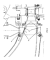
- FIG. 2 shows a more detailed illustration of a reintroduction manifold of an embodiment of the present application.
- the reintroduction manifold 19 may receive combustor bypass air through a conduit 18.
- the reintroduction manifold 19 may be in communication with one or more reintroduction slots 21 located in the wall of the combustor body 11.
- the reintroduction slots 21 may include a continuous annular slot located in the wall of the combustor body 11.
- the reintroduction slots 21 may include a number of slots located in the wall of the combustor body 11.
- the slots may be equally spaced from one another about the combustor body 11.
- the one or more reintroduction slots 21 generally may be in communication with the reintroduction manifold 19 through one or more holes 22 connecting the reintroduction slots 21 with the reintroduction manifold 19. After reintroduction, the combustor bypass air may pass to a first stage of the turbine section 24 where it may provide useful work.
- the combustor bypass flow through the reintroduction manifold 19 and the one or more reintroduction slots 21 generally is sufficient to provide cooling to the reintroduction manifold 19 and reintroduction slots 21 and to ensure that the temperatures are maintained within acceptable levels.
- the amount of combustor bypass flow is minimal and may be insufficient to maintain the temperature of the reintroduction manifold 19 and reintroduction slots 21 within acceptable levels.
- the combustor 10 of the present application may include a number of cooling holes 23 for providing cooling air to the one or more reintroduction slots 21.
- cooling air independent of the combustor bypass air may pass through the cooling holes 23 to provide cooling air to the one or more reintroduction slots 21.
- cooling air independent of the combustor bypass air may continuously pass through the cooling holes 23 to provide cooling air to the one or more reintroduction slots 21.
- air used to cool a combustor aft frame 25 may pass through the cooling holes 23 to provide a constant level of cooling to the reintroduction slots 21.
- the cooling holes 23 further may be sized to ensure that temperatures remain within acceptable levels during periods of minimum combustor bypass flow. Further, the low pressure region created by the reintroduction slots 21, the ejector effect of the cooling holes 23, and the cool air provided by the cooling holes 23 may provide additional backflow margin.
Landscapes
- Engineering & Computer Science (AREA)
- Chemical & Material Sciences (AREA)
- Combustion & Propulsion (AREA)
- Mechanical Engineering (AREA)
- General Engineering & Computer Science (AREA)
- Structures Of Non-Positive Displacement Pumps (AREA)
- Control Of Turbines (AREA)
- Engine Equipment That Uses Special Cycles (AREA)
Abstract
Description
- The present application relates generally to gas turbines and more particularly relates to systems and methods for reintroducing gas turbine combustion bypass flow.
- A gas turbine includes a compressor section that produces compressed air that is subsequently heated by burning a fuel in the reaction zone of a combustion section. The hot gas from the combustion section is directed to a turbine section where the hot gas is used to drive a rotor shaft to produce power. The combustion section typically includes a casing that forms a chamber that receives compressor discharge air from the compressor section. A number of cylindrical combustors typically are disposed in the chamber and receive the compressor discharge air along with the fuel to be burned. A duct is connected to the aft end of each combustor and serves to direct the hot gas from the combustor to the turbine section.
- Due to rising fuel costs, gas fired power plants that were designed to operate at mostly full power output are now being operated on a intermittent basis. Coal and nuclear energy generally may make up the majority of stable power output. Gas turbines increasingly are being used to make up the difference during peak demand periods. For example, a gas turbine may be used only during the daytime and then taken off line during the nighttime when the power demand is lower.
- During load reductions, or "turndowns," combustion systems must be capable of remaining in emissions compliance down to about fifty percent (50%) of full rated load output, or "base load." In order to maintain acceptable fuel-to-air ratios at the required turndown levels and to control the formation of oxides of nitrogen ("NOx") and carbon monoxide (CO), considered atmospheric pollutants, it is sometimes desirable to cause a portion of the compressor discharge air from the compressor section to bypass the combustors.
- Previous bypass systems have accomplished this by reinjecting the bypass flow as a dilution jet directly into the duct that directs the hot gas to the turbine. This approach may suffer from several drawbacks. Reinjecting the bypass flow as a single dilution jet can cause flame quenching and high levels of atmospheric pollutants in combustion systems. In addition, introducing combustor bypass air directly into the duct at one localized spot may create distortions in the temperature pattern and profile of the hot gas flowing into the turbine section. Moreover, the effect on pattern and profile generally cannot be tailored to meet downstream hardware thermal requirements.
- There is a desire therefore to provide an apparatus for causing a portion of the compressor discharge air to bypass the combustor and enter the hot gas flow path downstream of the combustor. Such a bypass may reduce the concern for quenching and atmospheric pollutants, prevent distortions in the gas temperature profile, and allow tailoring of the pattern and profile factors to meet downstream hardware thermal requirements.
- In one embodiment, the present application provides a combustor for a gas turbine. The combustor may include a combustor body, wherein the combustor body includes a reaction zone for primary combustion of fuel and air. The combustor also may include a casing enclosing the combustor body and defining an annular passageway for carrying compressor discharge air into the combustor body at one end thereof. The combustor further may include a reintroduction manifold for receiving combustor bypass air extracted from the compressor discharge air in the annular passageway, and one or more reintroduction slots in communication with the reintroduction manifold for injecting the combustor bypass air into the combustor body downstream of the reaction zone. The combustor also may include one or more cooling holes for providing cooling air to the one or more reintroduction slots.
- In another embodiment, the present application provides a combustor for a gas turbine. The combustor may include a combustor body, wherein the combustor body includes a reaction zone for primary combustion of fuel and air. The combustor also may include a casing enclosing the combustor body and defining an annular passageway for carrying compressor discharge air into the combustor body at one end thereof. The combustor further may include an extraction manifold for extracting combustor bypass air from the annular passageway, a reintroduction manifold for receiving combustor bypass air extracted from the annular passageway, and a conduit for transporting the combustor bypass air from the extraction manifold to the reintroduction manifold. The combustor also may include one or more reintroduction slots in communication with the reintroduction manifold for injecting the combustor bypass air into the combustor body downstream of the reaction zone, and one or more cooling holes for providing cooling air to the one or more reintroduction slots.
- In a further embodiment, the present application provides a method for bypassing a combustor of a gas turbine. The method may include extracting combustor bypass air from an annular passageway including compressor discharge air, wherein the annular passageway is defined by the space between a combustor body and a casing enclosing the combustor body. The method also may include transporting the combustor bypass air to a reintroduction manifold. The method further may include reintroducing the combustor bypass air into the combustor body through one or more reintroduction slots in communication with the reintroduction manifold, wherein the one or more reintroduction slots are downstream of a reaction zone in the combustor body.
- These and other features of the present application will become apparent to one of ordinary skill in the art upon review of the following detailed description when taken in conjunction with the several drawings and the appended claims.
- There follows a detailed description of embodiments of the invention by way of example only with reference to the accompanying drawings, in which:
-
FIG. 1 is a cross-sectional illustration of a combustor for a gas turbine as is described herein. -
FIG. 2 is a detailed illustration of a reintroduction manifold as is described herein. - Described below are embodiments of systems and methods for reintroducing gas turbine combustion bypass flow. Referring now to the drawings,
FIG. 1 shows a cross-sectional illustration of acombustor 10 of a gas turbine of an embodiment of the present application. The gas turbine further may include a compressor section and a turbine section (partially shown to the left and right of the combustor). - The
combustor 10 of the gas turbine may include acombustor body 11. Thecombustor 10 further may include acasing 12 enclosing thecombustor body 11. Together thecombustor body 11 and thecasing 12 may define anannular passageway 13. Generally described, theannular passageway 13 receives compressed air discharged from the compressor. Theannular passageway 13 carries the compressor discharge air to thecombustor body 11 to a head end 14 thereof. Thecombustor body 11 may further include a reaction zone 15 for the primary combustion of a fuel. The fuel and compressed air generally are introduced to the reaction zone 15 where they combust to form a hot gas. A duct 16 may form the aft end of thecombustor body 11. The duct 16 may direct the hot gas from the reaction zone 15 to a turbine where the hot gas may be expanded to drive a rotor shaft to produce power. - At certain predetermined turndown levels, it may be desirable to cause a portion of the compressor discharge air from the compressor section to bypass the reaction zone 15 of the
combustor 10. In accordance with an embodiment of the application, thecombustor 10 may include anextraction manifold 17 for extracting a portion of the compressor discharge air from theannular passageway 13. The portion of the compressor discharge air extracted from theannular passageway 13 forms the combustor bypass air. Theextraction manifold 17 may be in communication with aconduit 18 for transporting the combustor bypass air from theextraction manifold 17 to areintroduction manifold 19. Thecompressor 10 may further include avalve 20 to regulate the combustor bypass air flowing to thereintroduction manifold 19. In a particular embodiment, thevalve 20 may be disposed within theconduit 18. -
FIG. 2 shows a more detailed illustration of a reintroduction manifold of an embodiment of the present application. Thereintroduction manifold 19 may receive combustor bypass air through aconduit 18. Thereintroduction manifold 19 may be in communication with one ormore reintroduction slots 21 located in the wall of thecombustor body 11. In a particular embodiment of the application, thereintroduction slots 21 may include a continuous annular slot located in the wall of thecombustor body 11. In another embodiment of the application, thereintroduction slots 21 may include a number of slots located in the wall of thecombustor body 11. In yet another embodiment of the application, the slots may be equally spaced from one another about thecombustor body 11. The one ormore reintroduction slots 21 generally may be in communication with thereintroduction manifold 19 through one ormore holes 22 connecting thereintroduction slots 21 with thereintroduction manifold 19. After reintroduction, the combustor bypass air may pass to a first stage of theturbine section 24 where it may provide useful work. - At turndown levels, the combustor bypass flow through the
reintroduction manifold 19 and the one ormore reintroduction slots 21 generally is sufficient to provide cooling to thereintroduction manifold 19 andreintroduction slots 21 and to ensure that the temperatures are maintained within acceptable levels. At base load, however, the amount of combustor bypass flow is minimal and may be insufficient to maintain the temperature of thereintroduction manifold 19 andreintroduction slots 21 within acceptable levels. In particular embodiments, thecombustor 10 of the present application may include a number of cooling holes 23 for providing cooling air to the one ormore reintroduction slots 21. In particular embodiments, cooling air independent of the combustor bypass air may pass through the cooling holes 23 to provide cooling air to the one ormore reintroduction slots 21. In other embodiments, cooling air independent of the combustor bypass air may continuously pass through the cooling holes 23 to provide cooling air to the one ormore reintroduction slots 21. In still further embodiments, air used to cool a combustoraft frame 25 may pass through the cooling holes 23 to provide a constant level of cooling to thereintroduction slots 21. The cooling holes 23 further may be sized to ensure that temperatures remain within acceptable levels during periods of minimum combustor bypass flow. Further, the low pressure region created by thereintroduction slots 21, the ejector effect of the cooling holes 23, and the cool air provided by the cooling holes 23 may provide additional backflow margin. - For completeness, various aspects of the invention are now set out in the following numbered clauses:
- 1. A combustor for a gas turbine configured for reintroducing a combustor bypass air extracted from a compressor discharge air, comprising:
- a combustor body, wherein the combustor body comprises a reaction zone for primary combustion;
- a casing enclosing the combustor body and defining an annular passageway therebetween for carrying the compressor discharge air into the combustor body at one end thereof;
- a reintroduction manifold for receiving the combustor bypass air extracted from the compressor discharge air in the annular passageway;
- one or more reintroduction slots in communication with the reintroduction manifold for injecting the combustor bypass air into the combustor body downstream of the reaction zone; and
- one or more cooling holes for providing cooling air to the one or more reintroduction slots.
- 2. The combustor of clause 1, wherein the one or more cooling holes provides cooling air continuously to the one or more reintroduction slots.
- 3. The combustor of clause 1, further comprising a valve to regulate the combustor bypass air flowing to the reintroduction manifold.
- 4. The combustor of clause 1, further comprising an extraction manifold for extracting the combustor bypass air from the annular passageway.
- 5. The combustor of clause 4, further comprising a conduit for transporting the combustor bypass air from the extraction manifold to the reintroduction manifold.
- 6. The combustor of clause 1, wherein the one or more reintroduction slots comprise a continuous annular slot in communication with the reintroduction manifold.
- 7. The combustor of clause 1, wherein the one or more reintroduction slots comprise a plurality of slots in communication with the reintroduction manifold.
- 8. The combustor of clause 7, wherein the plurality of slots are equally spaced from one another about the combustor body.
- 9. A combustor for a gas turbine configured for reintroducing a combustor bypass air extracted from a compressor discharge air, comprising:
- a combustor body, wherein the combustor body comprises a reaction zone for primary combustion;
- a casing enclosing the combustor body and defining an annular passageway therebetween for carrying the compressor discharge air into the combustor body at one end thereof;
- an extraction manifold for extracting the combustor bypass air from the annular passageway;
- a reintroduction manifold for receiving the combustor bypass air extracted from the annular passageway;
- a conduit for transporting the combustor bypass air from the extraction manifold to the reintroduction manifold;
- one or more reintroduction slots in communication with the reintroduction manifold for injecting the combustor bypass air into the combustor body downstream of the reaction zone; and
- one or more cooling holes for providing cooling air to the one or more reintroduction slots.
- 10. The combustor of clause 9, wherein the one or more cooling holes provides cooling air continuously to the one or more reintroduction slots.
- 11. The combustor of clause 9, wherein the one or more reintroduction slots comprises a continuous annular slot in communication with the reintroduction manifold.
- 12. The combustor of clause 9, wherein the one or more reintroduction slots comprise a plurality of slots in communication with the reintroduction manifold.
- 13. The combustor of
clause 12, wherein the plurality of slots are equally spaced from one another about the combustor body. - 14. A method for bypassing a combustor bypass air around a combustor of a gas turbine, comprising:
- extracting the combustor bypass air from an annular passageway comprising compressor discharge air, wherein the annular passageway is defined by the space between a combustor body and a casing enclosing the combustor body;
- transporting the combustor bypass air to a reintroduction manifold; and
- reintroducing the combustor bypass air into the combustor body through one or more reintroduction slots in communication with the reintroduction manifold, wherein the one or more reintroduction slots are downstream of a reaction zone in the combustor body.
- 15. The method of clause 14, wherein transporting the combustor bypass air to a reintroduction manifold comprises transporting the combustor bypass air to the reintroduction manifold through a conduit.
- 16. The method of clause 14, further comprising regulating the transporting of the combustor bypass air to the reintroduction manifold using a valve.
- 17. The method of clause 14, further comprising providing cooling air to the one or more reintroduction slots through one or more cooling holes.
- 18. The method of clause 14, wherein the one or more reintroduction slots comprises a continuous annular slot in communication with the reintroduction manifold.
- 19. The method of clause 14, wherein the one or more reintroduction slots comprises a plurality of slots in communication with the reintroduction manifold.
- 20. The method of
clause 19, wherein the plurality of slots are equally spaced from one another about the combustor body.
Claims (15)
- A combustor (10) for a gas turbine configured for reintroducing a combustor bypass air extracted from a compressor discharge air, comprising:a combustor body (11), wherein the combustor body (11) comprises a reaction zone (15) for primary combustion;a casing (12) enclosing the combustor body (11) and defining an annular passageway (13) therebetween for carrying the compressor discharge air into the combustor body (11) at one end (14) thereof;a reintroduction manifold (19) for receiving the combustor bypass air extracted from the compressor discharge air in the annular passageway (13);one or more reintroduction slots (21) in communication with the reintroduction manifold (19) for injecting the combustor bypass air into the combustor body (11) downstream of the reaction zone (15); andone or more cooling holes (23) for providing cooling air to the one or more reintroduction slots (21).
- The combustor (10) of claim 1, wherein the one or more cooling holes (23) provides cooling air continuously to the one or more reintroduction slots (21).
- The combustor (10) of claim 1 or 2, further comprising a valve (20) to regulate the combustor bypass air flowing to the reintroduction manifold (19).
- The combustor (10) of any of the preceding claims, further comprising an extraction manifold (17) for extracting the combustor bypass air from the annular passageway (13).
- The combustor (10) of claim 4, further comprising a conduit (18) for transporting the combustor bypass air from the extraction manifold (17) to the reintroduction manifold (19).
- The combustor (10) of any of the preceding claims, wherein the one or more reintroduction slots (21) comprise a continuous annular slot in communication with the reintroduction manifold (19).
- The combustor (10) of any of claims 1 to 5, wherein the one or more reintroduction slots (21) comprise a plurality of slots in communication with the reintroduction manifold (19).
- The combustor (10) of claim 7, wherein the plurality of slots are equally spaced from one another about the combustor body (11).
- A combustor for a gas turbine configured for reintroducing a combustor bypass air extracted from a compressor discharge air, comprising:a combustor body, wherein the combustor body comprises a reaction zone for primary combustion;a casing enclosing the combustor body and defining an annular passageway therebetween for carrying the compressor discharge air into the combustor body at one end thereof;an extraction manifold for extracting the combustor bypass air from the annular passageway;a reintroduction manifold for receiving the combustor bypass air extracted from the annular passageway;a conduit for transporting the combustor bypass air from the extraction manifold to the reintroduction manifold;one or more reintroduction slots in communication with the reintroduction manifold for injecting the combustor bypass air into the combustor body downstream of the reaction zone; andone or more cooling holes for providing cooling air to the one or more reintroduction slots.
- A method for bypassing a combustor bypass air around a combustor of a gas turbine, comprising:extracting the combustor bypass air from an annular passageway comprising compressor discharge air, wherein the annular passageway is defined by the space between a combustor body and a casing enclosing the combustor body;transporting the combustor bypass air to a reintroduction manifold; andreintroducing the combustor bypass air into the combustor body through one or more reintroduction slots in communication with the reintroduction manifold, wherein the one or more reintroduction slots are downstream of a reaction zone in the combustor body.
- The method of claim 10, wherein transporting the combustor bypass air to a reintroduction manifold comprises transporting the combustor bypass air to the reintroduction manifold through a conduit.
- The method of claim 10 or 11, further comprising regulating the transporting of the combustor bypass air to the reintroduction manifold using a valve.
- The method of any of claims 10 to 12, further comprising providing cooling air to the one or more reintroduction slots through one or more cooling holes.
- The method of any of claims 10 to 13, wherein the one or more reintroduction slots comprises a continuous annular slot in communication with the reintroduction manifold.
- The method of claim 14, wherein the one or more reintroduction slots comprises a plurality of slots in communication with the reintroduction manifold.
Applications Claiming Priority (1)
| Application Number | Priority Date | Filing Date | Title |
|---|---|---|---|
| US12/408,326 US8281601B2 (en) | 2009-03-20 | 2009-03-20 | Systems and methods for reintroducing gas turbine combustion bypass flow |
Publications (2)
| Publication Number | Publication Date |
|---|---|
| EP2230457A2 true EP2230457A2 (en) | 2010-09-22 |
| EP2230457A3 EP2230457A3 (en) | 2017-11-08 |
Family
ID=42269549
Family Applications (1)
| Application Number | Title | Priority Date | Filing Date |
|---|---|---|---|
| EP10156373.2A Withdrawn EP2230457A3 (en) | 2009-03-20 | 2010-03-12 | Systems and methods for reintroducing gas turbine combustion bypass flow |
Country Status (4)
| Country | Link |
|---|---|
| US (1) | US8281601B2 (en) |
| EP (1) | EP2230457A3 (en) |
| JP (1) | JP5542486B2 (en) |
| CN (1) | CN101839482A (en) |
Cited By (1)
| Publication number | Priority date | Publication date | Assignee | Title |
|---|---|---|---|---|
| FR3070058A1 (en) * | 2017-08-14 | 2019-02-15 | Safran Aircraft Engines | AIRCRAFT TURBOMACHINE COMPRISING A COOLING ELEMENT IMPROVING CONVECTION COOLING AND PROVIDING AIR JET IMPACT COOLING OF AN ANNULAR COMBUSTION ROOM TERMINAL LINK FLANGE |
Families Citing this family (16)
| Publication number | Priority date | Publication date | Assignee | Title |
|---|---|---|---|---|
| EP2587021A1 (en) * | 2011-10-24 | 2013-05-01 | Siemens Aktiengesellschaft | Gas turbine and method for guiding compressed fluid in a gas turbine |
| DE102012204103A1 (en) * | 2012-03-15 | 2013-09-19 | Siemens Aktiengesellschaft | Heat shield element for a compressor air bypass around the combustion chamber |
| DE102012204162A1 (en) * | 2012-03-16 | 2013-09-19 | Siemens Aktiengesellschaft | Ring combustor bypass |
| US20140060073A1 (en) * | 2012-08-28 | 2014-03-06 | General Electric Company | Multiple point overboard extractor for gas turbine |
| US9376961B2 (en) * | 2013-03-18 | 2016-06-28 | General Electric Company | System for controlling a flow rate of a compressed working fluid to a combustor fuel injector |
| US20150107255A1 (en) * | 2013-10-18 | 2015-04-23 | General Electric Company | Turbomachine combustor having an externally fueled late lean injection (lli) system |
| EP3084137A4 (en) * | 2013-12-19 | 2017-01-25 | United Technologies Corporation | Turbine airfoil cooling |
| DE102014206018A1 (en) * | 2014-03-31 | 2015-10-01 | Siemens Aktiengesellschaft | Gas turbine plant |
| DE102014209544A1 (en) * | 2014-05-20 | 2015-11-26 | Siemens Aktiengesellschaft | turbine assembly |
| US10337411B2 (en) | 2015-12-30 | 2019-07-02 | General Electric Company | Auto thermal valve (ATV) for dual mode passive cooling flow modulation |
| US20170191373A1 (en) | 2015-12-30 | 2017-07-06 | General Electric Company | Passive flow modulation of cooling flow into a cavity |
| US10335900B2 (en) | 2016-03-03 | 2019-07-02 | General Electric Company | Protective shield for liquid guided laser cutting tools |
| US10337739B2 (en) | 2016-08-16 | 2019-07-02 | General Electric Company | Combustion bypass passive valve system for a gas turbine |
| US10712007B2 (en) | 2017-01-27 | 2020-07-14 | General Electric Company | Pneumatically-actuated fuel nozzle air flow modulator |
| US10738712B2 (en) | 2017-01-27 | 2020-08-11 | General Electric Company | Pneumatically-actuated bypass valve |
| US11530650B2 (en) | 2018-07-13 | 2022-12-20 | Raytheon Technologies Corporation | Gas turbine engine with active variable turbine cooling |
Family Cites Families (28)
| Publication number | Priority date | Publication date | Assignee | Title |
|---|---|---|---|---|
| NL70901C (en) * | 1945-01-23 | |||
| US3657882A (en) * | 1970-11-13 | 1972-04-25 | Westinghouse Electric Corp | Combustion apparatus |
| GB2041193B (en) * | 1979-02-20 | 1983-02-09 | Rolls Royce | Gas turbine engine combustion apparatus |
| US4487016A (en) * | 1980-10-01 | 1984-12-11 | United Technologies Corporation | Modulated clearance control for an axial flow rotary machine |
| US5048288A (en) * | 1988-12-20 | 1991-09-17 | United Technologies Corporation | Combined turbine stator cooling and turbine tip clearance control |
| JPH05203146A (en) | 1992-01-29 | 1993-08-10 | Hitachi Ltd | Gas turbine combustion apparatus and gas turbine power generator |
| US5394687A (en) * | 1993-12-03 | 1995-03-07 | The United States Of America As Represented By The Department Of Energy | Gas turbine vane cooling system |
| DE69421896T2 (en) | 1993-12-22 | 2000-05-31 | Siemens Westinghouse Power Corp., Orlando | Bypass valve for the combustion chamber of a gas turbine |
| US5619855A (en) * | 1995-06-07 | 1997-04-15 | General Electric Company | High inlet mach combustor for gas turbine engine |
| US5924276A (en) | 1996-07-17 | 1999-07-20 | Mowill; R. Jan | Premixer with dilution air bypass valve assembly |
| US5906093A (en) * | 1997-02-21 | 1999-05-25 | Siemens Westinghouse Power Corporation | Gas turbine combustor transition |
| US5819525A (en) * | 1997-03-14 | 1998-10-13 | Westinghouse Electric Corporation | Cooling supply manifold assembly for cooling combustion turbine components |
| US6065282A (en) * | 1997-10-29 | 2000-05-23 | Mitsubishi Heavy Industries, Ltd. | System for cooling blades in a gas turbine |
| JPH11201454A (en) * | 1997-12-31 | 1999-07-30 | R Jan Mowill | Combustor of improved convection cooling-single stage-complete premixing type with controllable air-fuel ratio |
| US6250061B1 (en) * | 1999-03-02 | 2001-06-26 | General Electric Company | Compressor system and methods for reducing cooling airflow |
| US6293088B1 (en) * | 1999-11-29 | 2001-09-25 | Siemens Westinghouse Power Corporation | Gas turbine with steam cooling and fuel atomization |
| US6574966B2 (en) * | 2000-06-08 | 2003-06-10 | Hitachi, Ltd. | Gas turbine for power generation |
| JP2002243154A (en) * | 2001-02-16 | 2002-08-28 | Mitsubishi Heavy Ind Ltd | Gas turbine combustor and tail cylinder outlet structure thereof |
| US6449956B1 (en) | 2001-04-09 | 2002-09-17 | General Electric Company | Bypass air injection method and apparatus for gas turbines |
| JP2002317650A (en) | 2001-04-24 | 2002-10-31 | Mitsubishi Heavy Ind Ltd | Gas turbine combustor |
| JP2003004233A (en) | 2001-06-26 | 2003-01-08 | Mitsubishi Heavy Ind Ltd | Bypass valve for compressed air and gas turbine |
| US20030024234A1 (en) * | 2001-08-02 | 2003-02-06 | Siemens Westinghouse Power Corporation | Secondary combustor for low NOx gas combustion turbine |
| BRPI0406806A (en) * | 2003-01-17 | 2005-12-27 | Catalytica Energy Sys Inc | Catalytic multi-fuel dynamic control system and method for gas turbine engine |
| US6860108B2 (en) * | 2003-01-22 | 2005-03-01 | Mitsubishi Heavy Industries, Ltd. | Gas turbine tail tube seal and gas turbine using the same |
| FR2858358B1 (en) * | 2003-07-28 | 2005-09-23 | Snecma Moteurs | METHOD FOR COOLING, BY COOLED AIR IN PART IN AN EXTERNAL EXCHANGER, HOT PARTS OF A TURBOJET ENGINE AND TURBOREACTOR THUS COOLED |
| US20060016195A1 (en) | 2003-09-16 | 2006-01-26 | Catalytica Energy Systems, Inc. | Bypass and injection method and apparatus for gas turbines |
| JP4274996B2 (en) * | 2004-04-27 | 2009-06-10 | 三菱重工業株式会社 | Gas turbine combustor |
| US20070151257A1 (en) * | 2006-01-05 | 2007-07-05 | Maier Mark S | Method and apparatus for enabling engine turn down |
-
2009
- 2009-03-20 US US12/408,326 patent/US8281601B2/en active Active
-
2010
- 2010-03-12 EP EP10156373.2A patent/EP2230457A3/en not_active Withdrawn
- 2010-03-16 JP JP2010058595A patent/JP5542486B2/en not_active Expired - Fee Related
- 2010-03-19 CN CN201010145537A patent/CN101839482A/en active Pending
Non-Patent Citations (1)
| Title |
|---|
| None |
Cited By (1)
| Publication number | Priority date | Publication date | Assignee | Title |
|---|---|---|---|---|
| FR3070058A1 (en) * | 2017-08-14 | 2019-02-15 | Safran Aircraft Engines | AIRCRAFT TURBOMACHINE COMPRISING A COOLING ELEMENT IMPROVING CONVECTION COOLING AND PROVIDING AIR JET IMPACT COOLING OF AN ANNULAR COMBUSTION ROOM TERMINAL LINK FLANGE |
Also Published As
| Publication number | Publication date |
|---|---|
| CN101839482A (en) | 2010-09-22 |
| US20100236249A1 (en) | 2010-09-23 |
| JP2010223222A (en) | 2010-10-07 |
| JP5542486B2 (en) | 2014-07-09 |
| EP2230457A3 (en) | 2017-11-08 |
| US8281601B2 (en) | 2012-10-09 |
Similar Documents
| Publication | Publication Date | Title |
|---|---|---|
| US8281601B2 (en) | Systems and methods for reintroducing gas turbine combustion bypass flow | |
| EP2957835B1 (en) | Method for recirculation of exhaust gas from a combustion chamber of a combustor of a gas turbine and gas turbine for conducting said method | |
| EP2912381B1 (en) | Sequential combustion with dilution gas mixer | |
| EP2894405B1 (en) | Sequential combustion arrangement with dilution gas | |
| JP5406460B2 (en) | Method and system for enabling operation within a flame holding margin | |
| CN106762158B (en) | System and method for operating a gas turbine while maintaining emission standards | |
| EP2857658A1 (en) | Gas turbine with sequential combustion arrangement | |
| CN101008351B (en) | Method and apparatus for enabling engine turn down | |
| EP3220047A1 (en) | Gas turbine flow sleeve mounting | |
| CA2936200C (en) | Combustor cooling system | |
| CN113864818B (en) | Combustor air flow path | |
| EP1967717A1 (en) | Gas turbine with a bypass conduit system | |
| US20170058770A1 (en) | System and method for decoupling steam production dependency from gas turbine load level | |
| EP3220049A1 (en) | Gas turbine combustor having liner cooling guide vanes | |
| CN106468449B (en) | Continuous combustion arrangement with cooling gas for dilution | |
| US10584643B2 (en) | Method for operating a supply assembly for supplying fuel gas and inert media to a gas turbine combustor, such supply assembly and a gas turbine comprising such supply assembly | |
| US20170058771A1 (en) | System and method for generating steam during gas turbine low-load conditions | |
| EP2896793B1 (en) | Method of operating a gas turbine assembly and the gas turbine assembly | |
| EP2828581B1 (en) | Combustion device |
Legal Events
| Date | Code | Title | Description |
|---|---|---|---|
| PUAI | Public reference made under article 153(3) epc to a published international application that has entered the european phase |
Free format text: ORIGINAL CODE: 0009012 |
|
| AK | Designated contracting states |
Kind code of ref document: A2 Designated state(s): AT BE BG CH CY CZ DE DK EE ES FI FR GB GR HR HU IE IS IT LI LT LU LV MC MK MT NL NO PL PT RO SE SI SK SM TR |
|
| AX | Request for extension of the european patent |
Extension state: AL BA ME RS |
|
| PUAL | Search report despatched |
Free format text: ORIGINAL CODE: 0009013 |
|
| AK | Designated contracting states |
Kind code of ref document: A3 Designated state(s): AT BE BG CH CY CZ DE DK EE ES FI FR GB GR HR HU IE IS IT LI LT LU LV MC MK MT NL NO PL PT RO SE SI SK SM TR |
|
| AX | Request for extension of the european patent |
Extension state: AL BA ME RS |
|
| RIC1 | Information provided on ipc code assigned before grant |
Ipc: F23R 3/04 20060101ALI20171002BHEP Ipc: F23R 3/26 20060101AFI20171002BHEP |
|
| STAA | Information on the status of an ep patent application or granted ep patent |
Free format text: STATUS: THE APPLICATION IS DEEMED TO BE WITHDRAWN |
|
| 18D | Application deemed to be withdrawn |
Effective date: 20180509 |