EP2230400A2 - Yaw assembly of a wind turbine and method of assembling the same - Google Patents
Yaw assembly of a wind turbine and method of assembling the same Download PDFInfo
- Publication number
- EP2230400A2 EP2230400A2 EP10155730A EP10155730A EP2230400A2 EP 2230400 A2 EP2230400 A2 EP 2230400A2 EP 10155730 A EP10155730 A EP 10155730A EP 10155730 A EP10155730 A EP 10155730A EP 2230400 A2 EP2230400 A2 EP 2230400A2
- Authority
- EP
- European Patent Office
- Prior art keywords
- yaw
- yaw drive
- output shafts
- gear
- planetary
- Prior art date
- Legal status (The legal status is an assumption and is not a legal conclusion. Google has not performed a legal analysis and makes no representation as to the accuracy of the status listed.)
- Withdrawn
Links
- 238000000034 method Methods 0.000 title description 17
- 230000005540 biological transmission Effects 0.000 claims description 21
- 230000000712 assembly Effects 0.000 description 28
- 238000000429 assembly Methods 0.000 description 28
- 230000006870 function Effects 0.000 description 15
- 230000008878 coupling Effects 0.000 description 11
- 238000010168 coupling process Methods 0.000 description 11
- 238000005859 coupling reaction Methods 0.000 description 11
- 230000007246 mechanism Effects 0.000 description 11
- 238000012546 transfer Methods 0.000 description 6
- 230000007423 decrease Effects 0.000 description 5
- 230000000694 effects Effects 0.000 description 2
- 238000004519 manufacturing process Methods 0.000 description 2
- 230000002093 peripheral effect Effects 0.000 description 2
- 229910000831 Steel Inorganic materials 0.000 description 1
- 238000007792 addition Methods 0.000 description 1
- 238000004891 communication Methods 0.000 description 1
- 238000013016 damping Methods 0.000 description 1
- 230000003247 decreasing effect Effects 0.000 description 1
- 238000012217 deletion Methods 0.000 description 1
- 230000037430 deletion Effects 0.000 description 1
- 230000009977 dual effect Effects 0.000 description 1
- 230000007717 exclusion Effects 0.000 description 1
- 239000012530 fluid Substances 0.000 description 1
- 238000012423 maintenance Methods 0.000 description 1
- 238000005259 measurement Methods 0.000 description 1
- 238000012986 modification Methods 0.000 description 1
- 230000004048 modification Effects 0.000 description 1
- 230000003287 optical effect Effects 0.000 description 1
- 238000010248 power generation Methods 0.000 description 1
- 230000008569 process Effects 0.000 description 1
- 238000012545 processing Methods 0.000 description 1
- 230000009467 reduction Effects 0.000 description 1
- 230000003068 static effect Effects 0.000 description 1
- 239000010959 steel Substances 0.000 description 1
Images




Classifications
-
- F—MECHANICAL ENGINEERING; LIGHTING; HEATING; WEAPONS; BLASTING
- F03—MACHINES OR ENGINES FOR LIQUIDS; WIND, SPRING, OR WEIGHT MOTORS; PRODUCING MECHANICAL POWER OR A REACTIVE PROPULSIVE THRUST, NOT OTHERWISE PROVIDED FOR
- F03D—WIND MOTORS
- F03D1/00—Wind motors with rotation axis substantially parallel to the air flow entering the rotor
-
- F—MECHANICAL ENGINEERING; LIGHTING; HEATING; WEAPONS; BLASTING
- F03—MACHINES OR ENGINES FOR LIQUIDS; WIND, SPRING, OR WEIGHT MOTORS; PRODUCING MECHANICAL POWER OR A REACTIVE PROPULSIVE THRUST, NOT OTHERWISE PROVIDED FOR
- F03D—WIND MOTORS
- F03D7/00—Controlling wind motors
- F03D7/02—Controlling wind motors the wind motors having rotation axis substantially parallel to the air flow entering the rotor
- F03D7/0204—Controlling wind motors the wind motors having rotation axis substantially parallel to the air flow entering the rotor for orientation in relation to wind direction
-
- F—MECHANICAL ENGINEERING; LIGHTING; HEATING; WEAPONS; BLASTING
- F05—INDEXING SCHEMES RELATING TO ENGINES OR PUMPS IN VARIOUS SUBCLASSES OF CLASSES F01-F04
- F05B—INDEXING SCHEME RELATING TO WIND, SPRING, WEIGHT, INERTIA OR LIKE MOTORS, TO MACHINES OR ENGINES FOR LIQUIDS COVERED BY SUBCLASSES F03B, F03D AND F03G
- F05B2260/00—Function
- F05B2260/40—Transmission of power
- F05B2260/403—Transmission of power through the shape of the drive components
- F05B2260/4031—Transmission of power through the shape of the drive components as in toothed gearing
- F05B2260/40311—Transmission of power through the shape of the drive components as in toothed gearing of the epicyclic, planetary or differential type
-
- F—MECHANICAL ENGINEERING; LIGHTING; HEATING; WEAPONS; BLASTING
- F05—INDEXING SCHEMES RELATING TO ENGINES OR PUMPS IN VARIOUS SUBCLASSES OF CLASSES F01-F04
- F05B—INDEXING SCHEME RELATING TO WIND, SPRING, WEIGHT, INERTIA OR LIKE MOTORS, TO MACHINES OR ENGINES FOR LIQUIDS COVERED BY SUBCLASSES F03B, F03D AND F03G
- F05B2270/00—Control
- F05B2270/30—Control parameters, e.g. input parameters
- F05B2270/328—Blade pitch angle
-
- F—MECHANICAL ENGINEERING; LIGHTING; HEATING; WEAPONS; BLASTING
- F16—ENGINEERING ELEMENTS AND UNITS; GENERAL MEASURES FOR PRODUCING AND MAINTAINING EFFECTIVE FUNCTIONING OF MACHINES OR INSTALLATIONS; THERMAL INSULATION IN GENERAL
- F16H—GEARING
- F16H37/00—Combinations of mechanical gearings, not provided for in groups F16H1/00 - F16H35/00
- F16H37/02—Combinations of mechanical gearings, not provided for in groups F16H1/00 - F16H35/00 comprising essentially only toothed or friction gearings
- F16H37/06—Combinations of mechanical gearings, not provided for in groups F16H1/00 - F16H35/00 comprising essentially only toothed or friction gearings with a plurality of driving or driven shafts; with arrangements for dividing torque between two or more intermediate shafts
- F16H37/08—Combinations of mechanical gearings, not provided for in groups F16H1/00 - F16H35/00 comprising essentially only toothed or friction gearings with a plurality of driving or driven shafts; with arrangements for dividing torque between two or more intermediate shafts with differential gearing
- F16H37/0806—Combinations of mechanical gearings, not provided for in groups F16H1/00 - F16H35/00 comprising essentially only toothed or friction gearings with a plurality of driving or driven shafts; with arrangements for dividing torque between two or more intermediate shafts with differential gearing with a plurality of driving or driven shafts
- F16H37/0826—Combinations of mechanical gearings, not provided for in groups F16H1/00 - F16H35/00 comprising essentially only toothed or friction gearings with a plurality of driving or driven shafts; with arrangements for dividing torque between two or more intermediate shafts with differential gearing with a plurality of driving or driven shafts with only one output shaft
-
- Y—GENERAL TAGGING OF NEW TECHNOLOGICAL DEVELOPMENTS; GENERAL TAGGING OF CROSS-SECTIONAL TECHNOLOGIES SPANNING OVER SEVERAL SECTIONS OF THE IPC; TECHNICAL SUBJECTS COVERED BY FORMER USPC CROSS-REFERENCE ART COLLECTIONS [XRACs] AND DIGESTS
- Y02—TECHNOLOGIES OR APPLICATIONS FOR MITIGATION OR ADAPTATION AGAINST CLIMATE CHANGE
- Y02E—REDUCTION OF GREENHOUSE GAS [GHG] EMISSIONS, RELATED TO ENERGY GENERATION, TRANSMISSION OR DISTRIBUTION
- Y02E10/00—Energy generation through renewable energy sources
- Y02E10/70—Wind energy
- Y02E10/72—Wind turbines with rotation axis in wind direction
-
- Y—GENERAL TAGGING OF NEW TECHNOLOGICAL DEVELOPMENTS; GENERAL TAGGING OF CROSS-SECTIONAL TECHNOLOGIES SPANNING OVER SEVERAL SECTIONS OF THE IPC; TECHNICAL SUBJECTS COVERED BY FORMER USPC CROSS-REFERENCE ART COLLECTIONS [XRACs] AND DIGESTS
- Y10—TECHNICAL SUBJECTS COVERED BY FORMER USPC
- Y10T—TECHNICAL SUBJECTS COVERED BY FORMER US CLASSIFICATION
- Y10T29/00—Metal working
- Y10T29/49—Method of mechanical manufacture
- Y10T29/49826—Assembling or joining
Definitions
- the field of the disclosure relates generally to wind turbine generators and, more particularly, to control devices for use on wind turbine generators.
- At least some known wind turbine generators include a rotor having multiple blades.
- the rotor is sometimes coupled to a housing, or nacelle, that is positioned on top of a base, for example, a truss or tubular tower.
- At least some known utility grade wind turbines i.e., wind turbines designed to provide electrical power to a utility grid
- the rotor blades transform mechanical wind energy into induced blade lift forces that further induce a mechanical rotational torque that drives one or more generators, subsequently generating electric power.
- the generators are sometimes, but not always, rotationally coupled to the rotor through a gearbox.
- the gearbox steps up the inherently low rotational speed of the turbine rotor for the generator to efficiently convert the rotational mechanical energy to electrical energy, which is fed into the electric utility grid.
- Gearless direct drive wind turbine generators also exist.
- a yawing device may be used to orient the wind turbine into the direction of the wind.
- Some known yawing devices include an electrical or hydraulic motor and a high-ratio gear that acts on the toothed path of the yaw bearing and thus turns the machinery into the desired position. Due to the influence of wind shear, for example, the machinery is subjected to pulsating forces, both when yawing and when the machinery is stationary. These forces often have a dominating tendency in one direction, which means that they tend to turn the wind turbine out of the direction of the wind.
- yawing devices include a single input shaft that receives a torque from a motor located within the wind turbine, and translates this torque via a plurality of gearing assemblies to a single output torque shaft that facilitates yawing the wind turbine.
- numerous yawing devices are required within each wind turbine to supply the force needed to yaw the wind turbine, especially under less-than-optimal weather conditions, i.e. in high winds.
- a yaw drive assembly for a rotatable system.
- the yaw drive assembly includes an input shaft configured to receive a torque from a yaw drive motor coupled within a body of the rotatable system, wherein the torque facilitates rotating the rotatable system about a yaw axis.
- the yaw drive assembly includes at least two output shafts configured to receive the torque and transmit a rotational yaw force to the rotatable system, and a differential gear stage operatively coupled to the two output shafts, wherein the differential gear stage includes a differential planetary gear configured to drive a pinion coupled to each of the two output shafts.
- a wind turbine in another aspect, includes a yaw drive motor, and at least one yaw drive assembly operatively coupled to the motor.
- the yaw drive assembly includes an input shaft configured to receive a torque from a yaw drive motor coupled within a body of the rotatable system, wherein the torque facilitates rotating the rotatable system about a yaw axis.
- the yaw drive assembly includes at least two output shafts configured to receive the torque and transmit a rotational yaw force to the rotatable system, and a differential gear stage operatively coupled to the two output shafts, wherein the differential gear stage includes a differential planetary gear configured to drive a pinion coupled to each of the two output shafts.
- a method for assembling a rotatable system includes coupling a yaw drive assembly to a yaw drive motor via a yaw drive assembly input shaft, wherein the input shaft is configured to receive a torque from the yaw drive motor coupled within a body of the rotatable system, and wherein the torque facilitates rotating the rotatable system about a yaw axis.
- the method includes extending at least two output shafts from the yaw drive assembly, wherein the two output shafts are configured to transmit a rotational yaw force to the rotatable system.
- the method includes operatively coupling a differential gear stage to the two output shafts, wherein the differential gear stage includes a differential planetary gear that is configured to drive a pinion coupled to each of the two output shafts.
- FIG. 1 is a schematic view of an exemplary wind turbine generator 100.
- wind turbine generator 100 is a horizontal axis wind turbine.
- wind turbine generator 100 may be a vertical axis wind turbine.
- Wind turbine generator 100 has a tower 102 extending from a supporting surface 104, a nacelle 106 coupled to tower 102, and a rotor 108 coupled to nacelle 106.
- Rotor 108 has a rotatable hub 110 and a plurality of rotor blades 112 coupled to hub 110.
- rotor 108 has three rotor blades 112.
- rotor 108 has any number of rotor blades 112 that enables wind turbine generator 100 to function as described herein.
- tower 102 is fabricated from tubular steel and has a cavity (not shown in Figure 1 ) extending between supporting surface 104 and nacelle 106.
- tower 102 is any tower that enables wind turbine generator 100 to function as described herein including, but not limited to, a lattice tower.
- the height of tower 102 is any value that enables wind turbine generator 100 to function as described herein.
- Blades 112 are positioned about rotor hub 110 to facilitate rotating rotor 108, thereby transferring kinetic energy from wind 124 into usable mechanical energy, and subsequently, electrical energy.
- Rotor 108 and nacelle 106 are rotated about tower 102 on a yaw axis 116 to control the perspective of blades 112 with respect to the direction of wind 124.
- Blades 112 are mated to hub 110 by coupling a blade root portion 120 to hub 110 at a plurality of load transfer regions 122.
- Load transfer regions 122 have a hub load transfer region and a blade load transfer region (both not shown in Figure 1 ). Loads induced in blades 112 are transferred to hub 110 via load transfer regions 122.
- Each blade 112 also includes a blade tip portion 125.
- blades 112 have a length between 50 meters (m) (164 feet (ft)) and 100 m (328 ft), however these parameters form no limitations to the instant disclosure.
- blades 112 may have any length that enables wind turbine generator to function as described herein.
- a pitch angle (not shown) of blades 112 i.e., an angle that determines a perspective of each blade 112 with respect to the direction of wind 124, may be changed by a pitch adjustment mechanism (not shown in Figure 1 ). Specifically, increasing a pitch angle of blade 112 decreases a percentage of area 126 exposed to wind 124 and, conversely, decreasing a pitch angle of blade 112 increases a percentage of area 126 exposed to wind 124.
- a blade pitch angle of approximately 0 degrees (sometimes referred to as a "power position”) exposes a significant percentage of a blade surface area 126 to wind 124, thereby resulting in inducement of a first value of lift forces on blade 112.
- a blade pitch angle of approximately 90 degrees (sometimes referred to as a “feathered position”) exposes a significantly lower percentage of blade surface area 126 to wind 124, thereby resulting in inducement of a second value of lift forces on blade 112.
- the first value of lift forces induced on blades 112 is greater than the second value of lift forces induced on blades 112 such that values of lift forces are directly proportional to blade surface area 126 exposed to wind 124. Therefore, values of lift forces induced on blades 112 are indirectly proportional to values of blade pitch angle.
- the pitch angles of blades 112 are adjusted about a pitch axis 118 for each blade 112.
- the pitch angles of blades 112 are controlled individually.
- the pitch angles may be controlled as a group.
- the pitch of the blades, and the speed of the blades 112 may be modulated in order to reduce acoustic emissions.
- wind turbine generator 100 may be controlled to reduce the potential acoustic emissions by a local controller (not shown), or remotely via a remote controller (not shown) to reduce noise.
- FIG 2 is a cross-sectional schematic view of nacelle 106 of exemplary wind turbine generator 100.
- Various components of wind turbine generator 100 are housed in nacelle 106 atop tower 102 of wind turbine generator 100.
- Nacelle 106 includes one pitch drive mechanism 130 that is coupled to one blade 112 (shown in Figure 1 ).
- Mechanism 130 modulates the pitch of associated blade 112 along pitch axis 118. Only one of three pitch drive mechanisms 130 is shown in Figure 2 .
- each pitch drive mechanism 130 includes at least one pitch drive motor 131
- Pitch drive motor 131 is any electric motor driven by electrical power that enables mechanism 130 to function as described herein.
- pitch drive mechanisms 130 include any suitable structure, configuration, arrangement, and/or components such as, but not limited to, hydraulic cylinders, springs, and servomechanisms. Moreover, pitch drive mechanisms 130 may be driven by any suitable means such as, but not limited to, hydraulic fluid, and/or mechanical power, such as, but not limited to, induced spring forces and/or electromagnetic forces.
- Nacelle 106 also includes rotor 108 that is rotatably coupled to an electric generator 132 positioned within nacelle 106 via rotor shaft 134 (sometimes referred to as low speed shaft 134), a gearbox 136, a high speed shaft 138, and a coupling 140.
- Rotation of rotor shaft 134 rotatably drives gearbox 136 that subsequently rotatably drives high speed shaft 138.
- High speed shaft 138 rotatably drives generator 132 via coupling 140 and shaft 138 rotation facilitates generator 132 production of electrical power.
- Gearbox 136 and generator 132 are supported by supports 142 and 144, respectively.
- gearbox 136 utilizes a dual path geometry to drive high speed shaft 138.
- main rotor shaft 134 is coupled directly to generator 132 via coupling 140.
- Nacelle 106 further includes a yaw drive assembly 146 that is fixedly coupled to a lower bed plate 147 and that engages a tower ring gear 148 that may be used to rotate nacelle 106 and rotor 108 on axis 116 (shown in Figure 1 ) to control the perspective of blades 112 with respect to the direction of the wind, as described in more detail herein.
- Nacelle 106 also includes at least one meteorological mast 149.
- Mast 149 includes a wind vane and anemometer (neither shown in Figure 2 ).
- Mast 149 provides information to a turbine control system (not shown) that may include wind direction and/or wind speed. A portion of the turbine control system resides within a control panel 150.
- Nacelle 106 further includes forward and aft support bearings 152 and 154 that facilitate radial support and alignment of rotor shaft 134.
- Wind turbine generator 100 includes a pitch control system 200.
- pitch control system 200 is positioned in nacelle 106.
- at least a portion of pitch control system 200 is positioned outside nacelle 106.
- at least a portion of pitch control system 200 described herein includes at least one processor 202 and a memory device (not shown), and at least one input/output (I/O) conduit 204, wherein conduit 204 includes at least one I/O channel (not shown).
- processor 202 is positioned within control panel 150.
- Pitch control system 200 substantially provides a technical effect of wind turbine noise reduction as described herein.
- processor is not limited to just those integrated circuits referred to in the art as a computer, but broadly refers to a microcontroller, a microcomputer, a programmable logic controller (PLC), an application specific integrated circuit, and other programmable circuits, and these terms are used interchangeably herein.
- memory may include, but is not limited to, a computer-readable medium, such as a random access memory (RAM), and a computer-readable non-volatile medium, such as flash memory.
- RAM random access memory
- flash memory such as a computer-readable non-volatile medium
- floppy disk, a compact disc - read only memory (CD-ROM), a magneto-optical disk (MOD), and/or a digital versatile disc (DVD) may also be used.
- additional input channels may be, but not be limited to, computer peripherals associated with an operator interface such as a mouse and a keyboard.
- other computer peripherals may also be used that may include, for example, but not be limited to, a scanner.
- additional output channels may include, but not be limited to, an operator interface monitor.
- Processor 202 and other processors (not shown) as described herein process information transmitted from a plurality of electrical and electronic devices that may include, but not be limited to, blade pitch position feedback devices 206 (described further below) and electric power generation feedback devices (not shown).
- RAM and storage devices store and transfer information and instructions to be executed by processor 202. RAM and storage devices can also be used to store and provide temporary variables, static (i.e., non-changing) information and instructions, or other intermediate information to processor 202 during execution of instructions by processor 202.
- Instructions that are executed include, but are not limited to, resident blade pitch system 200 control commands. The execution of sequences of instructions is not limited to any specific combination of hardware circuitry and software instructions.
- At least a portion of pitch control system 200 including, but not limited to, processor 202 is positioned within control panel 150. Moreover, processor 202 is coupled to blade pitch drive motors 131 via at least one I/O conduit 204. I/O conduit 204 includes any number of channels having any architecture including, but not limited to, Cat 5/6 cable, twisted pair wiring, and wireless communication features. Pitch control system 200 may include distributed and/or centralized control architectures.
- Pitch control system 200 also includes a plurality of independent blade pitch position feedback devices 206 coupled with processor 202 via at least one I/O conduit 204.
- each pitch drive mechanism 130 is associated with a single blade pitch position feedback device 206.
- any number of blade pitch position feedback devices 206 are associated with each mechanism 130. Therefore, in the exemplary embodiment, pitch drive mechanism 130 and associated drive motor 131, as well as blade pitch position feedback device 206, are included in system 200 as described herein.
- Each blade pitch position feedback device 206 measures a pitch position of each blade 112, or more specifically an angle of each blade 112 with respect to wind 124 (shown in Figure 1 ) and/or with respect to rotor hub 110.
- Blade pitch position feedback device 206 is any suitable sensor having any suitable location within or remote to wind turbine generator 100, such as, but not limited to, optical angle encoders, magnetic rotary encoders, and incremental encoders, or some combination thereof. Moreover, blade pitch position feedback device 206 transmits pitch measurement signals (not shown) that are substantially representative of associated blade 112 pitch position to processor 202 for processing thereof.
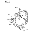
- FIG 3 is a perspective view of exemplary yaw drive assemblies 300 and 302 used with exemplary wind turbine generator 100 shown in Figure 1 .
- wind turbine generator 100 includes two yaw drive assemblies 300 and 302 that are positioned substantially radially opposite each other about a yaw axis of rotation 304.
- any number of yaw drive assemblies may be included that enables wind turbine generator 100 to function as described herein.
- a substantially similar drive assembly may be used to control pitch of rotor blades 112 (shown in Figure 1 ) for wind turbine generator 100.
- yaw drive assemblies 300 and 302 are coupled to a lower bed plate 306 that is positioned atop wind turbine tower 102 (as shown in Figure 2 ) such that yaw drive assemblies engage tower ring gear 148 (shown in Figure 2 ) that is coupled to wind turbine tower 102, and such that wind turbine generator 100 may function as described herein.
- Yaw drive assemblies 300 and 302 include a transmission case 308 that substantially encloses each yaw drive assembly 300 and 302 and maintains internal gearing components therein.
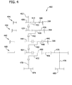
- FIG 4 is a schematic illustration of an exemplary gearing structure 400 used with exemplary yaw drive assemblies 300 and 302 shown in Figure 3 .
- an input shaft 402 is rotatably supported within transmission case 308 and is operatively coupled to a first stage planetary assembly 404.
- First stage planetary assembly 404 includes an input sun gear 406 that receives a torque transmitted thereto by input shaft 402 and a ring gear 408 that is fixedly coupled within transmission case 308.
- a planetary gear 410 is operatively coupled between sun gear 406 and ring gear 408.
- any number of planetary gears 410 may be used within first stage planetary assembly 404 to transmit the input torque from input shaft 402, such that yaw drive assemblies 300 and 302 may function as described herein.
- planetary gear 410 transmits the input torque to a second stage planetary assembly 420 via a force transmission rod 422.
- Second stage planetary assembly 420 includes an input sun gear 424 that receives a torque transmitted thereto via force transmission rod 422, and a ring gear 426 that is fixedly coupled within transmission case 308.
- a planetary gear 428 is operatively coupled between sun gear 424 and ring gear 426.
- any number of planetary gears 428 may be used within second stage planetary assembly 420 to transmit the input torque from input shaft 402, such that yaw drive assemblies 300 and 302 may function as described herein.
- planetary gear 428 transmits the input torque to a third stage planetary assembly 440 via a force transmission rod 442.
- Third stage planetary assembly 440 includes an input sun gear 444 that receives a torque transmitted thereto via force transmission rod 442, and a ring gear 446 that is fixedly coupled within transmission case 308.
- a planetary gear 448 is operatively coupled between sun gear 444 and ring gear 446.
- any number of planetary gears 448 may be used within third stage planetary assembly 440 to transmit the input torque from input shaft 402, such that yaw drive assemblies 300 and 302 may function as described herein.
- planetary gear 448 transmits the input torque to a fourth stage planetary assembly 460 via a force transmission rod 462.
- Fourth stage planetary assembly 460 includes an input sun gear 464 that receives a torque transmitted thereto via force transmission rod 462, and a differential gear 466.
- a planetary gear 468 is operatively coupled between sun gear 464 and differential gear 466.
- any number of planetary gears 468 may be used within fourth stage planetary assembly 460 to transmit the input torque from input shaft 402, such that yaw drive assemblies 300 and 302 may function as described herein.
- Planetary gear 468 transmits the input torque to a first output shaft 470 via a force transmission rod 472.
- a first output pinion 474 is coupled to first output shaft 470 and engages tower ring gear 148 (shown in Figure 2 ) to apply torque thereto for yawing wind turbine generator 100 about axis 116 (shown in Figure 1 ).
- Differential gear 466 engages an output gear 476.
- output gear 476 is a spur gear that engages differential gear 466 and transmits the output torque to a second output shaft 478.
- output gear 476 may be any type of gear that enables yaw drive assemblies 300 and 302 to function as described herein, such as for example a helical gear.
- a second output pinion 480 is coupled to output shaft 478 and engages tower ring gear 148 (shown in Figure 2 ) to apply torque thereto for yawing wind turbine generator 100 about axis 116 (shown in Figure 1 ).
- first and second output shafts 470 and 478 distribute the input rotational yaw force substantially equally along tower ring gear 148 to facilitate rotation of wind turbine generator 100 about axis 116.
- FIG. 5 is a schematic illustration of an exemplary differential stage 500 suitable for use with exemplary gearing structure 400 shown in Figure 4 .
- fourth stage planetary assembly 460 is housed within a case 502 that is coupled to lower bed plate 147 via a plurality of bolts 504.
- case 502 may be coupled to lower bed plate 147 via any type of fastening device, or combination thereof, that enables yaw drive assemblies 300 and 302 to function as described herein, such as for example by a weld and/or a screw.
- differential gear 466 is supported within case 502 via a plurality of bearings 508 and 510
- gear 476 (shown in Figure 4 ) is supported by bearings 512 and 513.
- gear 476 may be supported by only bearing 512.
- Input sun gear 464 is rotationally supported within case 502 and first and second output shafts 470 and 478 are rotationally supported within case 502 via a plurality of bearings.
- yaw drive assemblies 300 and 302 utilize multiple output shafts, thereby reducing the number of yaw drive assemblies required per wind turbine generator 100. More specifically, the exemplary yaw drive assembly configuration described herein enables the use of two output pinions to facilitate supplying the torque typically produced by two separate yaw drives. Therefore, the number of yaw drive assemblies is reduced.
- FIG 6 is a schematic illustration of an alternative gearing structure 600 that may be used with the exemplary yaw drive assembly shown in Figure 3 .
- the operation of gearing structure 600 is similar to gearing structure 400 shown in Figure 4 and described herein. Therefore, like components are similarly numbered therein.
- gearing structure 600 is similar to the embodiment illustrated in Figure 4
- gearing structure 600 incorporates a third output gearing assembly 602 using an additional output spur gear 604 positioned within fourth planetary assembly 460. More specifically, third output gearing assembly 602 includes output gear 604 that engages differential gear 466.
- output gear 604 is a spur gear that engages differential gear 466 and transmits the output torque to a third output shaft 606.
- output gear 604 may be any type of gear that enables yaw drive assemblies 300 and 302 to function as described herein, such as for example a helical gear.
- a third output pinion 608 is coupled to output shaft 606 and engages tower ring gear 148 (shown in Figure 2 ) to apply torque thereto for yawing and/or pitching wind turbine generator 100 (shown in Figure 1 ).
- any number of output gear, shaft and pinion combinations may be used that enables wind turbine generator 100 to function as described herein.
- such an alternative gearing structure 600 will distribute the input rotational yaw force substantially equally along tower ring gear 148 to facilitate rotation of wind turbine generator 100 about axis 116.
- FIG 7 is a schematic illustration of an alternative gearing structure 700 that may be used with the exemplary yaw drive assemblies 300 and 302 shown in Figure 3 .
- the operation of gearing structure 700 is similar to gearing structure 400 shown in Figure 4 and described herein. Therefore, like components are similarly numbered therein.
- gearing structure 700 incorporates a second output planetary gearing assembly 702. More specifically, and in the illustrated alternative embodiment, fifth stage planetary assembly 702 includes a sun gear 706, a differential gear 708 that engages differential gear 466, and planetary gear 704 is operatively coupled between sun gear 706 and differential gear 708.
- Planetary gear 704 transmits the input torque to a second output shaft 710 via a force transmission rod 712.
- the second output pinion 714 is coupled to second output shaft 710 and engages tower ring gear 148 (shown in Figure 2 ) to apply torque thereto for yawing wind turbine generator 100 about axis 116 (shown in Figure 1 ).
- more than one planetary assembly 460 may be provided such that more than one output transmits torque to tower ring gear (shown in Figure 2 ).
- yaw drive assemblies utilize multiple output shaft assemblies to facilitate reducing the number of yaw drive assemblies per wind turbine. More specifically, the last stage of the yaw drive assembly may include a differential planetary gear that enables the use of two output pinions to facilitate supplying the torque produced by two separate yaw drives. Therefore, the number of yaw drive assemblies may be reduced by 50%, i.e. two yaw drive assemblies may be used instead of four yaw drive assemblies per wind turbine, and therefore a weight of the overall wind turbine yaw drive system is facilitated being reduced. This may result in a control system that can be optimized to a smaller size, and minimizes the number of working components, thereby simplifying manufacturing, assembly, and maintenance of the wind turbine generator.
- such a system may reduce a backlash effect common in known wind turbines, and enables a more effective utilization of the control system by providing a yaw drive assembly that is easier to control with increased accuracy by improving damping against fluctuating wind loads.
- the fewer number of rotating components for the amount of torque transmitted may result in a system with an improved life of the yawing gear components.
Landscapes
- Engineering & Computer Science (AREA)
- Life Sciences & Earth Sciences (AREA)
- Sustainable Development (AREA)
- Sustainable Energy (AREA)
- Chemical & Material Sciences (AREA)
- Combustion & Propulsion (AREA)
- Mechanical Engineering (AREA)
- General Engineering & Computer Science (AREA)
- Wind Motors (AREA)
- Retarders (AREA)
Abstract
Description
- The field of the disclosure relates generally to wind turbine generators and, more particularly, to control devices for use on wind turbine generators.
- At least some known wind turbine generators include a rotor having multiple blades. The rotor is sometimes coupled to a housing, or nacelle, that is positioned on top of a base, for example, a truss or tubular tower. At least some known utility grade wind turbines (i.e., wind turbines designed to provide electrical power to a utility grid) have rotor blades having predetermined shapes and dimensions. The rotor blades transform mechanical wind energy into induced blade lift forces that further induce a mechanical rotational torque that drives one or more generators, subsequently generating electric power. The generators are sometimes, but not always, rotationally coupled to the rotor through a gearbox. The gearbox steps up the inherently low rotational speed of the turbine rotor for the generator to efficiently convert the rotational mechanical energy to electrical energy, which is fed into the electric utility grid. Gearless direct drive wind turbine generators also exist.
- During operation of such known wind turbines, a yawing device may be used to orient the wind turbine into the direction of the wind. Some known yawing devices include an electrical or hydraulic motor and a high-ratio gear that acts on the toothed path of the yaw bearing and thus turns the machinery into the desired position. Due to the influence of wind shear, for example, the machinery is subjected to pulsating forces, both when yawing and when the machinery is stationary. These forces often have a dominating tendency in one direction, which means that they tend to turn the wind turbine out of the direction of the wind.
- Known yawing devices include a single input shaft that receives a torque from a motor located within the wind turbine, and translates this torque via a plurality of gearing assemblies to a single output torque shaft that facilitates yawing the wind turbine. However, because of the limited rotational force that can be applied by a single output shaft, numerous yawing devices are required within each wind turbine to supply the force needed to yaw the wind turbine, especially under less-than-optimal weather conditions, i.e. in high winds.
- In one aspect according to the present invention, a yaw drive assembly for a rotatable system is provided. The yaw drive assembly includes an input shaft configured to receive a torque from a yaw drive motor coupled within a body of the rotatable system, wherein the torque facilitates rotating the rotatable system about a yaw axis. The yaw drive assembly includes at least two output shafts configured to receive the torque and transmit a rotational yaw force to the rotatable system, and a differential gear stage operatively coupled to the two output shafts, wherein the differential gear stage includes a differential planetary gear configured to drive a pinion coupled to each of the two output shafts.
- In another aspect, a wind turbine is provided. The wind turbine includes a yaw drive motor, and at least one yaw drive assembly operatively coupled to the motor. The yaw drive assembly includes an input shaft configured to receive a torque from a yaw drive motor coupled within a body of the rotatable system, wherein the torque facilitates rotating the rotatable system about a yaw axis. The yaw drive assembly includes at least two output shafts configured to receive the torque and transmit a rotational yaw force to the rotatable system, and a differential gear stage operatively coupled to the two output shafts, wherein the differential gear stage includes a differential planetary gear configured to drive a pinion coupled to each of the two output shafts.
- In yet another aspect, a method for assembling a rotatable system is provided. The method includes coupling a yaw drive assembly to a yaw drive motor via a yaw drive assembly input shaft, wherein the input shaft is configured to receive a torque from the yaw drive motor coupled within a body of the rotatable system, and wherein the torque facilitates rotating the rotatable system about a yaw axis. The method includes extending at least two output shafts from the yaw drive assembly, wherein the two output shafts are configured to transmit a rotational yaw force to the rotatable system. The method includes operatively coupling a differential gear stage to the two output shafts, wherein the differential gear stage includes a differential planetary gear that is configured to drive a pinion coupled to each of the two output shafts.
- Non-limiting and non-exhaustive embodiments are described with reference to the following figures, wherein like reference numerals refer to like parts throughout the various views unless otherwise specified, in which:
-
Figure 1 is a side elevation view of an exemplary wind turbine generator. -
Figure 2 is a cross-sectional schematic view of a nacelle used with the exemplary wind turbine generator shown inFigure 1 . -
Figure 3 is a perspective view of an exemplary yaw drive assembly used with the exemplary wind turbine generator shown inFigure 1 . -
Figure 4 is a schematic illustration of an exemplary gearing structure used with the exemplary yaw drive assembly shown inFigure 3 . -
Figure 5 is a schematic illustration of an exemplary differential stage used with the exemplary gearing structure shown inFigure 4 . -
Figure 6 is a schematic illustration of an alternative gearing structure that may be used with the exemplary yaw drive assembly shown inFigure 3 . -
Figure 7 is a schematic illustration of an alternative gearing structure that may be used with the exemplary yaw drive assembly shown inFigure 3 . -
Figure 1 is a schematic view of an exemplarywind turbine generator 100. In the exemplary embodiment,wind turbine generator 100 is a horizontal axis wind turbine. Alternatively,wind turbine generator 100 may be a vertical axis wind turbine.Wind turbine generator 100 has atower 102 extending from a supportingsurface 104, anacelle 106 coupled totower 102, and arotor 108 coupled tonacelle 106.Rotor 108 has arotatable hub 110 and a plurality ofrotor blades 112 coupled tohub 110. In the exemplary embodiment,rotor 108 has threerotor blades 112. Alternatively,rotor 108 has any number ofrotor blades 112 that enableswind turbine generator 100 to function as described herein. In the exemplary embodiment,tower 102 is fabricated from tubular steel and has a cavity (not shown inFigure 1 ) extending between supportingsurface 104 andnacelle 106. Alternatively,tower 102 is any tower that enableswind turbine generator 100 to function as described herein including, but not limited to, a lattice tower. The height oftower 102 is any value that enableswind turbine generator 100 to function as described herein. -
Blades 112 are positioned aboutrotor hub 110 to facilitate rotatingrotor 108, thereby transferring kinetic energy fromwind 124 into usable mechanical energy, and subsequently, electrical energy.Rotor 108 andnacelle 106 are rotated abouttower 102 on ayaw axis 116 to control the perspective ofblades 112 with respect to the direction ofwind 124.Blades 112 are mated tohub 110 by coupling ablade root portion 120 tohub 110 at a plurality ofload transfer regions 122.Load transfer regions 122 have a hub load transfer region and a blade load transfer region (both not shown inFigure 1 ). Loads induced inblades 112 are transferred tohub 110 viaload transfer regions 122. Eachblade 112 also includes ablade tip portion 125. - In the exemplary embodiment,
blades 112 have a length between 50 meters (m) (164 feet (ft)) and 100 m (328 ft), however these parameters form no limitations to the instant disclosure. Alternatively,blades 112 may have any length that enables wind turbine generator to function as described herein. Aswind 124 strikes eachblade 112, blade lift forces (not shown) are induced on eachblade 112 and rotation ofrotor 108 aboutrotation axis 114 is induced asblade tip portions 125 are accelerated. A pitch angle (not shown) ofblades 112, i.e., an angle that determines a perspective of eachblade 112 with respect to the direction ofwind 124, may be changed by a pitch adjustment mechanism (not shown inFigure 1 ). Specifically, increasing a pitch angle ofblade 112 decreases a percentage ofarea 126 exposed towind 124 and, conversely, decreasing a pitch angle ofblade 112 increases a percentage ofarea 126 exposed towind 124. - For example, a blade pitch angle of approximately 0 degrees (sometimes referred to as a "power position") exposes a significant percentage of a
blade surface area 126 towind 124, thereby resulting in inducement of a first value of lift forces onblade 112. Similarly, a blade pitch angle of approximately 90 degrees (sometimes referred to as a "feathered position") exposes a significantly lower percentage ofblade surface area 126 towind 124, thereby resulting in inducement of a second value of lift forces onblade 112. The first value of lift forces induced onblades 112 is greater than the second value of lift forces induced onblades 112 such that values of lift forces are directly proportional toblade surface area 126 exposed towind 124. Therefore, values of lift forces induced onblades 112 are indirectly proportional to values of blade pitch angle. - Also, for example, as blade lift forces increase, a linear speed of
blade tip portion 125 increases. Conversely, as blade lift forces decrease, the linear speed ofblade tip portion 125 decreases. Therefore, values of the linear speed ofblade tip portion 125 are directly proportional to values of the lift forces induced onblades 112 and it follows that the linear speed ofblade tip portion 125 is indirectly proportional to the blade pitch angle. - Moreover, as the linear speed of
blade tip portion 125 increases, an amplitude (not shown) of acoustic emissions (not shown inFigure 1 ) fromblade 112 increases. Conversely, as the linear speed ofblade tip portion 125 decreases, the amplitude of acoustic emissions fromblades 112 decreases. Therefore, the amplitude of acoustic emissions fromblades 112 is directly proportional to the linear speed ofblade tip portions 125 and, it follows that the amplitude of acoustic emissions fromblades 112 is indirectly proportional to the blade pitch angle. - The pitch angles of
blades 112 are adjusted about apitch axis 118 for eachblade 112. In the exemplary embodiment, the pitch angles ofblades 112 are controlled individually. Alternatively, the pitch angles may be controlled as a group. Still further alternatively, the pitch of the blades, and the speed of theblades 112 may be modulated in order to reduce acoustic emissions. In one embodiment,wind turbine generator 100 may be controlled to reduce the potential acoustic emissions by a local controller (not shown), or remotely via a remote controller (not shown) to reduce noise. -
Figure 2 is a cross-sectional schematic view ofnacelle 106 of exemplarywind turbine generator 100. Various components ofwind turbine generator 100 are housed innacelle 106 atoptower 102 ofwind turbine generator 100.Nacelle 106 includes onepitch drive mechanism 130 that is coupled to one blade 112 (shown inFigure 1 ).Mechanism 130 modulates the pitch of associatedblade 112 alongpitch axis 118. Only one of threepitch drive mechanisms 130 is shown inFigure 2 . In the exemplary embodiment, eachpitch drive mechanism 130 includes at least onepitch drive motor 131Pitch drive motor 131 is any electric motor driven by electrical power that enablesmechanism 130 to function as described herein. Alternatively,pitch drive mechanisms 130 include any suitable structure, configuration, arrangement, and/or components such as, but not limited to, hydraulic cylinders, springs, and servomechanisms. Moreover,pitch drive mechanisms 130 may be driven by any suitable means such as, but not limited to, hydraulic fluid, and/or mechanical power, such as, but not limited to, induced spring forces and/or electromagnetic forces. -
Nacelle 106 also includesrotor 108 that is rotatably coupled to anelectric generator 132 positioned withinnacelle 106 via rotor shaft 134 (sometimes referred to as low speed shaft 134), agearbox 136, ahigh speed shaft 138, and acoupling 140. Rotation ofrotor shaft 134 rotatably drivesgearbox 136 that subsequently rotatably driveshigh speed shaft 138.High speed shaft 138 rotatably drivesgenerator 132 viacoupling 140 andshaft 138 rotation facilitatesgenerator 132 production of electrical power.Gearbox 136 andgenerator 132 are supported bysupports gearbox 136 utilizes a dual path geometry to drivehigh speed shaft 138. Alternatively,main rotor shaft 134 is coupled directly togenerator 132 viacoupling 140. -
Nacelle 106 further includes ayaw drive assembly 146 that is fixedly coupled to alower bed plate 147 and that engages atower ring gear 148 that may be used to rotatenacelle 106 androtor 108 on axis 116 (shown inFigure 1 ) to control the perspective ofblades 112 with respect to the direction of the wind, as described in more detail herein.Nacelle 106 also includes at least onemeteorological mast 149.Mast 149 includes a wind vane and anemometer (neither shown inFigure 2 ).Mast 149 provides information to a turbine control system (not shown) that may include wind direction and/or wind speed. A portion of the turbine control system resides within acontrol panel 150.Nacelle 106 further includes forward andaft support bearings rotor shaft 134. -
Wind turbine generator 100 includes apitch control system 200. In one embodiment, at least a portion ofpitch control system 200 is positioned innacelle 106. Alternatively, at least a portion ofpitch control system 200 is positioned outsidenacelle 106. Specifically, at least a portion ofpitch control system 200 described herein includes at least oneprocessor 202 and a memory device (not shown), and at least one input/output (I/O)conduit 204, whereinconduit 204 includes at least one I/O channel (not shown). More specifically,processor 202 is positioned withincontrol panel 150.Pitch control system 200 substantially provides a technical effect of wind turbine noise reduction as described herein. - As used herein, the term processor is not limited to just those integrated circuits referred to in the art as a computer, but broadly refers to a microcontroller, a microcomputer, a programmable logic controller (PLC), an application specific integrated circuit, and other programmable circuits, and these terms are used interchangeably herein. In the embodiments described herein, memory may include, but is not limited to, a computer-readable medium, such as a random access memory (RAM), and a computer-readable non-volatile medium, such as flash memory. Alternatively, a floppy disk, a compact disc - read only memory (CD-ROM), a magneto-optical disk (MOD), and/or a digital versatile disc (DVD) may also be used. Also, in the embodiments described herein, additional input channels may be, but not be limited to, computer peripherals associated with an operator interface such as a mouse and a keyboard. Alternatively, other computer peripherals may also be used that may include, for example, but not be limited to, a scanner. Furthermore, in the exemplary embodiment, additional output channels may include, but not be limited to, an operator interface monitor.
-
Processor 202 and other processors (not shown) as described herein process information transmitted from a plurality of electrical and electronic devices that may include, but not be limited to, blade pitch position feedback devices 206 (described further below) and electric power generation feedback devices (not shown). RAM and storage devices (not shown) store and transfer information and instructions to be executed byprocessor 202. RAM and storage devices can also be used to store and provide temporary variables, static (i.e., non-changing) information and instructions, or other intermediate information toprocessor 202 during execution of instructions byprocessor 202. Instructions that are executed include, but are not limited to, residentblade pitch system 200 control commands. The execution of sequences of instructions is not limited to any specific combination of hardware circuitry and software instructions. - In the exemplary embodiment, at least a portion of
pitch control system 200 including, but not limited to,processor 202 is positioned withincontrol panel 150. Moreover,processor 202 is coupled to bladepitch drive motors 131 via at least one I/O conduit 204. I/O conduit 204 includes any number of channels having any architecture including, but not limited to, Cat 5/6 cable, twisted pair wiring, and wireless communication features.Pitch control system 200 may include distributed and/or centralized control architectures. -
Pitch control system 200 also includes a plurality of independent blade pitchposition feedback devices 206 coupled withprocessor 202 via at least one I/O conduit 204. In the exemplary embodiment, eachpitch drive mechanism 130 is associated with a single blade pitchposition feedback device 206. Alternatively, any number of blade pitchposition feedback devices 206 are associated with eachmechanism 130. Therefore, in the exemplary embodiment,pitch drive mechanism 130 and associateddrive motor 131, as well as blade pitchposition feedback device 206, are included insystem 200 as described herein. Each blade pitchposition feedback device 206 measures a pitch position of eachblade 112, or more specifically an angle of eachblade 112 with respect to wind 124 (shown inFigure 1 ) and/or with respect torotor hub 110. Blade pitchposition feedback device 206 is any suitable sensor having any suitable location within or remote towind turbine generator 100, such as, but not limited to, optical angle encoders, magnetic rotary encoders, and incremental encoders, or some combination thereof. Moreover, blade pitchposition feedback device 206 transmits pitch measurement signals (not shown) that are substantially representative of associatedblade 112 pitch position toprocessor 202 for processing thereof. -
Figure 3 is a perspective view of exemplaryyaw drive assemblies wind turbine generator 100 shown inFigure 1 . In the exemplary embodiment,wind turbine generator 100 includes twoyaw drive assemblies rotation 304. Alternatively, any number of yaw drive assemblies may be included that enableswind turbine generator 100 to function as described herein. In one embodiment, a substantially similar drive assembly may be used to control pitch of rotor blades 112 (shown inFigure 1 ) forwind turbine generator 100. - In the exemplary embodiment,
yaw drive assemblies lower bed plate 306 that is positioned atop wind turbine tower 102 (as shown inFigure 2 ) such that yaw drive assemblies engage tower ring gear 148 (shown inFigure 2 ) that is coupled towind turbine tower 102, and such thatwind turbine generator 100 may function as described herein. Yaw driveassemblies transmission case 308 that substantially encloses eachyaw drive assembly -
Figure 4 is a schematic illustration of anexemplary gearing structure 400 used with exemplaryyaw drive assemblies Figure 3 . In the exemplary embodiment, aninput shaft 402 is rotatably supported withintransmission case 308 and is operatively coupled to a first stageplanetary assembly 404. First stageplanetary assembly 404 includes aninput sun gear 406 that receives a torque transmitted thereto byinput shaft 402 and aring gear 408 that is fixedly coupled withintransmission case 308. In the exemplary embodiment, aplanetary gear 410 is operatively coupled betweensun gear 406 andring gear 408. Alternatively, any number ofplanetary gears 410 may be used within first stageplanetary assembly 404 to transmit the input torque frominput shaft 402, such thatyaw drive assemblies - In the exemplary embodiment,
planetary gear 410 transmits the input torque to a second stageplanetary assembly 420 via aforce transmission rod 422. Second stageplanetary assembly 420 includes aninput sun gear 424 that receives a torque transmitted thereto viaforce transmission rod 422, and aring gear 426 that is fixedly coupled withintransmission case 308. In the exemplary embodiment, aplanetary gear 428 is operatively coupled betweensun gear 424 andring gear 426. Alternatively, any number ofplanetary gears 428 may be used within second stageplanetary assembly 420 to transmit the input torque frominput shaft 402, such thatyaw drive assemblies - In the exemplary embodiment,
planetary gear 428 transmits the input torque to a third stageplanetary assembly 440 via aforce transmission rod 442. Third stageplanetary assembly 440 includes aninput sun gear 444 that receives a torque transmitted thereto viaforce transmission rod 442, and aring gear 446 that is fixedly coupled withintransmission case 308. In the exemplary embodiment, aplanetary gear 448 is operatively coupled betweensun gear 444 andring gear 446. Alternatively, any number ofplanetary gears 448 may be used within third stageplanetary assembly 440 to transmit the input torque frominput shaft 402, such thatyaw drive assemblies - In the exemplary embodiment,
planetary gear 448 transmits the input torque to a fourth stageplanetary assembly 460 via aforce transmission rod 462. Fourth stageplanetary assembly 460 includes aninput sun gear 464 that receives a torque transmitted thereto viaforce transmission rod 462, and adifferential gear 466. In the exemplary embodiment, aplanetary gear 468 is operatively coupled betweensun gear 464 anddifferential gear 466. Alternatively, any number ofplanetary gears 468 may be used within fourth stageplanetary assembly 460 to transmit the input torque frominput shaft 402, such thatyaw drive assemblies Planetary gear 468 transmits the input torque to afirst output shaft 470 via aforce transmission rod 472. Afirst output pinion 474 is coupled tofirst output shaft 470 and engages tower ring gear 148 (shown inFigure 2 ) to apply torque thereto for yawingwind turbine generator 100 about axis 116 (shown inFigure 1 ). -
Differential gear 466 engages anoutput gear 476. In the exemplary embodiment,output gear 476 is a spur gear that engagesdifferential gear 466 and transmits the output torque to asecond output shaft 478. Alternatively,output gear 476 may be any type of gear that enablesyaw drive assemblies second output pinion 480 is coupled tooutput shaft 478 and engages tower ring gear 148 (shown inFigure 2 ) to apply torque thereto for yawingwind turbine generator 100 about axis 116 (shown inFigure 1 ). In the exemplary embodiment, first andsecond output shafts tower ring gear 148 to facilitate rotation ofwind turbine generator 100 aboutaxis 116. -
Figure 5 is a schematic illustration of an exemplarydifferential stage 500 suitable for use withexemplary gearing structure 400 shown inFigure 4 . In the exemplary embodiment, fourth stageplanetary assembly 460 is housed within acase 502 that is coupled tolower bed plate 147 via a plurality ofbolts 504. Alternatively,case 502 may be coupled tolower bed plate 147 via any type of fastening device, or combination thereof, that enablesyaw drive assemblies - In the exemplary embodiment,
differential gear 466 is supported withincase 502 via a plurality ofbearings Figure 4 ) is supported bybearings gear 476 may be supported by only bearing 512.Input sun gear 464 is rotationally supported withincase 502 and first andsecond output shafts case 502 via a plurality of bearings. - During operation,
yaw drive assemblies wind turbine generator 100. More specifically, the exemplary yaw drive assembly configuration described herein enables the use of two output pinions to facilitate supplying the torque typically produced by two separate yaw drives. Therefore, the number of yaw drive assemblies is reduced. -
Figure 6 is a schematic illustration of analternative gearing structure 600 that may be used with the exemplary yaw drive assembly shown inFigure 3 . The operation of gearingstructure 600 is similar to gearingstructure 400 shown inFigure 4 and described herein. Therefore, like components are similarly numbered therein. However, while gearingstructure 600 is similar to the embodiment illustrated inFigure 4 , gearingstructure 600 incorporates a thirdoutput gearing assembly 602 using an additionaloutput spur gear 604 positioned within fourthplanetary assembly 460. More specifically, thirdoutput gearing assembly 602 includesoutput gear 604 that engagesdifferential gear 466. In the illustrated alternative embodiment,output gear 604 is a spur gear that engagesdifferential gear 466 and transmits the output torque to athird output shaft 606. Alternatively,output gear 604 may be any type of gear that enablesyaw drive assemblies third output pinion 608 is coupled tooutput shaft 606 and engages tower ring gear 148 (shown inFigure 2 ) to apply torque thereto for yawing and/or pitching wind turbine generator 100 (shown inFigure 1 ). Alternatively, any number of output gear, shaft and pinion combinations may be used that enableswind turbine generator 100 to function as described herein. During operations, such analternative gearing structure 600 will distribute the input rotational yaw force substantially equally alongtower ring gear 148 to facilitate rotation ofwind turbine generator 100 aboutaxis 116. -
Figure 7 is a schematic illustration of analternative gearing structure 700 that may be used with the exemplaryyaw drive assemblies Figure 3 . The operation of gearingstructure 700 is similar to gearingstructure 400 shown inFigure 4 and described herein. Therefore, like components are similarly numbered therein. However, while gearingstructure 700 is similar to the embodiment illustrated inFigure 4 , gearingstructure 700 incorporates a second outputplanetary gearing assembly 702. More specifically, and in the illustrated alternative embodiment, fifth stageplanetary assembly 702 includes asun gear 706, adifferential gear 708 that engagesdifferential gear 466, andplanetary gear 704 is operatively coupled betweensun gear 706 anddifferential gear 708.Planetary gear 704 transmits the input torque to asecond output shaft 710 via aforce transmission rod 712. Thesecond output pinion 714 is coupled tosecond output shaft 710 and engages tower ring gear 148 (shown inFigure 2 ) to apply torque thereto for yawingwind turbine generator 100 about axis 116 (shown inFigure 1 ). In an alternative embodiment, more than oneplanetary assembly 460 may be provided such that more than one output transmits torque to tower ring gear (shown inFigure 2 ). - Exemplary embodiments of yaw drive assemblies are described in detail above. The above-described yaw drive assemblies utilize multiple output shaft assemblies to facilitate reducing the number of yaw drive assemblies per wind turbine. More specifically, the last stage of the yaw drive assembly may include a differential planetary gear that enables the use of two output pinions to facilitate supplying the torque produced by two separate yaw drives. Therefore, the number of yaw drive assemblies may be reduced by 50%, i.e. two yaw drive assemblies may be used instead of four yaw drive assemblies per wind turbine, and therefore a weight of the overall wind turbine yaw drive system is facilitated being reduced. This may result in a control system that can be optimized to a smaller size, and minimizes the number of working components, thereby simplifying manufacturing, assembly, and maintenance of the wind turbine generator.
- Furthermore, such a system may reduce a backlash effect common in known wind turbines, and enables a more effective utilization of the control system by providing a yaw drive assembly that is easier to control with increased accuracy by improving damping against fluctuating wind loads. The fewer number of rotating components for the amount of torque transmitted may result in a system with an improved life of the yawing gear components.
- Although the foregoing description contains many specifics, these should not be construed as limiting the scope of the present invention, but merely as providing illustrations of some of the embodiments. Similarly, other embodiments of the invention may be devised which do not depart from the spirit or scope of the present invention. Features from different embodiments may be employed in combination. The scope of the invention is, therefore, indicated and limited only by the appended claims and their legal equivalents, rather than by the foregoing description. All additions, deletions and modifications to the invention as disclosed herein which fall within the meaning and scope of the claims are to be embraced thereby.
- While the apparatus and methods described herein are described in the context of yaw drive assemblies for use with wind turbine systems, it is understood that the apparatus and methods are not limited to wind turbine applications but may include yaw and/or pitch drive assemblies utilized within any rotatable machine. Likewise, the system components illustrated are not limited to the specific embodiments described herein, but rather, system components can be utilized independently and separately from other components described herein.
- As used herein, an element or step recited in the singular and proceeded with the word "a" or "an" should be understood as not excluding plural elements or steps, unless such exclusion is explicitly recited. Furthermore, references to "one embodiment" of the present invention are not intended to be interpreted as excluding the existence of additional embodiments that also incorporate the recited features.
- This written description uses examples to disclose the invention, including the preferred mode, and also to enable any person skilled in the art to practice the invention, including making and using any devices or systems and performing any incorporated methods. The patentable scope of the invention is defined by the claims, and may include other examples that occur to those skilled in the art. Such other examples are intended to be within the scope of the claims if they have structural elements that do not differ from the literal language of the claims, or if they include equivalent structural elements with insubstantial differences from the literal language of the claims.
- Various aspects and embodiments of the present invention are defined by the following numbered clauses:
- 1. A yaw drive assembly for a rotatable system, said yaw drive assembly comprising:
- an input shaft configured to receive a torque from a yaw drive motor coupled within a body of said rotatable system, the torque facilitates rotating the rotatable system about a yaw axis;
- at least two output shafts configured to receive the torque and transmit a rotational yaw force to the rotatable system; and
- a differential gear stage operatively coupled to said output shafts, said differential gear stage comprising a differential planetary gear configured to drive a pinion coupled to each of said output shafts.
- 2. A yaw drive assembly in accordance with Clause 1, wherein said output shafts comprise a spur gear configured to operatively engage said differential gear stage via said differential planetary gear.
- 3. A yaw drive assembly in accordance with any preceding Clause, further comprising at least one planetary stage rotatably coupled between said input shaft and said output shafts, each said planetary stage comprising at least one planetary gear.
- 4. A yaw drive assembly in accordance with any preceding Clause, wherein said planetary stage comprises at least three planetary stages operatively coupled between said input shaft and said differential planetary gear via respective planetary gears.
- 5. A yaw drive assembly in accordance with any preceding Clause, wherein said yaw drive assembly further comprises a transmission case configured to substantially enclose said yaw drive assembly, and wherein said planetary stage further comprises a ring gear fixedly coupled to an interior of said transmission case.
- 6. A yaw drive assembly in accordance with any preceding Clause, wherein said output shafts are operatively coupled in parallel via said differential gear stage, said output shafts configured to engage a ring gear coupled to an upper portion of the rotatable system via the respective pinion.
- 7. A yaw drive assembly in accordance with any preceding Clause, wherein said output shafts are configured to distribute the rotational yaw force substantially equally along a surface of said ring gear.
- 8. A wind turbine comprising:
- a yaw drive motor;
- at least one yaw drive assembly operatively coupled to said yaw drive motor, said yaw drive assembly comprising:
- an input shaft configured to receive a torque from said yaw drive motor coupled within a body of said wind turbine, the torque facilitates rotating said wind turbine about a yaw axis;
- at least two output shafts configured to receive the torque and transmit a rotational yaw force to said wind turbine; and
- a differential gear stage operatively coupled to said output shafts, said differential gear stage comprising a differential planetary gear configured to drive a pinion coupled to each of said output shafts.
- 9. A wind turbine in accordance with any preceding Clause, wherein said output shafts comprise a spur gear configured to operatively engage said differential gear stage via said differential planetary gear.
- 10. A wind turbine in accordance with any preceding Clause, further comprising at least one planetary stage rotatably coupled between said input shaft and said output shafts, each said planetary stage comprising at least one planetary gear.
- 11. A wind turbine in accordance with any preceding Clause, wherein said planetary stage comprises at least three planetary stages operatively coupled between said input shaft and said differential gear via respective planetary gears.
- 12. A wind turbine in accordance with any preceding Clause, wherein said yaw drive assembly further comprises a transmission case configured to substantially enclose said yaw drive assembly, and wherein said planetary stage further comprises a ring gear fixedly coupled to an interior of said transmission case.
- 13. A wind turbine in accordance with any preceding Clause, wherein said output shafts are operatively coupled in parallel via said differential gear stage, said output shafts configured to engage a ring gear coupled to an upper portion of said wind turbine via the respective pinion.
- 14. A wind turbine in accordance with any preceding Clause, wherein said output shafts are configured to distribute the rotational yaw force substantially equally along a surface of said ring gear.
- 15. A method for assembling a rotatable system, said method comprising:
- coupling a yaw drive assembly to a yaw drive motor via an input shaft, the input shaft configured to receive a torque from a yaw drive motor coupled within a body of the rotatable system, the torque facilitates rotating the rotatable system about a yaw axis;
- extending at least two output shafts from the yaw drive assembly, the output shafts configured to transmit a rotational yaw force to the rotatable system; and
- operatively coupling a differential gear stage to the output shafts, the differential gear stage including a differential planetary gear configured to drive a pinion coupled to each of the output shafts.
- 16. A method in accordance with Clause 15, wherein said method comprises providing a spur gear on each of the output shafts, the spur gear configured to operatively engage the differential gear stage via the differential planetary gear.
- 17. A method in accordance with Clause 15 or 16, further comprising distributing the rotational yaw force substantially equally along a surface of a ring gear of the planetary stage.
- 18. A method in accordance with any of Clauses 15 to 17, further comprising rotatably coupling at least one planetary stage between the input shaft and the output shafts, the planetary stage including at least one planet gear.
- 19. A method in accordance with any of Clauses 15 to 18, further comprising:
- substantially enclosing the yaw drive assembly within a transmission case; and
- fixedly coupling the ring gear to an interior of the transmission case.
- 20. A method in accordance with any of Clauses 15 to 19, further comprising operatively coupling the output shafts in parallel via the differential gear stage, the output shafts configured to engage a ring gear coupled to an upper portion of the rotatable system via the respective pinion.
Claims (10)
- A yaw drive assembly (146) for a rotatable system, said yaw drive assembly comprising:an input shaft (402) configured to receive a torque from a yaw drive motor coupled within a body of said rotatable system, the torque facilitates rotating the rotatable system about a yaw axis (116);at least two output shafts (470,478,606,710) configured to receive the torque and transmit a rotational yaw force to the rotatable system; anda differential gear stage (500) operatively coupled to said output shafts, said differential gear stage comprising a differential planetary gear (704) configured to drive a pinion (474,480,608,714) coupled to each of said output shafts.
- A yaw drive assembly (146) in accordance with Claim 1, wherein said output shafts (470,478,606,710) comprise a spur gear (476) configured to operatively engage said differential gear stage via said differential planetary gear (428,448,468).
- A yaw drive assembly (146) in accordance with any preceding Claim, further comprising at least one planetary stage rotatably coupled between said input shaft (402) and said output shafts (470,478,606,710), each said planetary stage comprising at least one planetary gear (428,448,468).
- A yaw drive assembly (146) in accordance with Claim 3, wherein said planetary stage (404,420,440,460,702) comprises at least three planetary stages operatively coupled between said input shaft and said differential planetary gear via respective planetary gears (428,448,468).
- A yaw drive assembly (146) in accordance with Claim 3 or Claim 4, wherein said yaw drive assembly further comprises a transmission case (308) configured to substantially enclose said yaw drive assembly, and wherein said planetary stage (404,420,440,460,702) further comprises a ring gear (148,408,446) fixedly coupled to an interior of said transmission case (308).
- A yaw drive assembly (146) in accordance with any preceding Claim, wherein said output shafts (470,478,606,710) are operatively coupled in parallel via said differential gear stage, said output shafts configured to engage a ring gear (148,408,446) coupled to an upper portion of the rotatable system via the respective pinion (474,480,608,714).
- A yaw drive assembly (146) in accordance with Claim 6, wherein said output shafts (470,478,606,710) are configured to distribute the rotational yaw force substantially equally along a surface of said ring gear (148,408,446).
- A wind turbine comprising:a yaw drive motor;at least one yaw drive assembly (142) operatively coupled to said yaw drive motor, said yaw drive assembly comprising:an input shaft (402) configured to receive a torque from said yaw drive motor coupled within a body of said wind turbine, the torque facilitates rotating said wind turbine about a yaw axis (116);at least two output shafts (470,478,606,710) configured to receive the torque and transmit a rotational yaw force to said wind turbine; anda differential gear stage (500) operatively coupled to said output shafts, said differential gear stage comprising a differential planetary gear configured to drive a pinion (474,480,608,714) coupled to each of said output shafts.
- A wind turbine in accordance with Claim 8, wherein said output shafts (470,478,606,710) comprise a spur gear (476) configured to operatively engage said differential gear stage (500) via said differential planetary gear (428,448,468).
- A wind turbine in accordance with Claim 8 or Claim 9, further comprising at least one planetary stage (404,420,440,460,702) rotatably coupled between said input shaft (402) and said output shafts (470,478,606,710), each said planetary stage comprising at least one planetary gear (428,448,468).
Applications Claiming Priority (1)
| Application Number | Priority Date | Filing Date | Title |
|---|---|---|---|
| US12/407,366 US7828686B2 (en) | 2009-03-19 | 2009-03-19 | Yaw assembly for a rotatable system and method of assembling the same |
Publications (2)
| Publication Number | Publication Date |
|---|---|
| EP2230400A2 true EP2230400A2 (en) | 2010-09-22 |
| EP2230400A3 EP2230400A3 (en) | 2014-04-23 |
Family
ID=42072911
Family Applications (1)
| Application Number | Title | Priority Date | Filing Date |
|---|---|---|---|
| EP10155730.4A Withdrawn EP2230400A3 (en) | 2009-03-19 | 2010-03-08 | Yaw assembly of a wind turbine and method of assembling the same |
Country Status (3)
| Country | Link |
|---|---|
| US (1) | US7828686B2 (en) |
| EP (1) | EP2230400A3 (en) |
| CN (1) | CN101839215B (en) |
Families Citing this family (21)
| Publication number | Priority date | Publication date | Assignee | Title |
|---|---|---|---|---|
| CN102705162B (en) * | 2003-08-12 | 2014-10-22 | 纳博特斯克株式会社 | Yaw drive device for wind power generator |
| JP4959439B2 (en) * | 2007-06-22 | 2012-06-20 | 三菱重工業株式会社 | Wind power generator |
| US8298115B2 (en) * | 2008-07-10 | 2012-10-30 | General Electric Company | Wind turbine transmission assembly |
| US8203230B2 (en) * | 2010-06-29 | 2012-06-19 | General Electric Company | Yaw bearing system |
| US8310080B2 (en) * | 2010-08-04 | 2012-11-13 | General Electric Company | Yaw assembly for use in wind turbines |
| CN102003342B (en) * | 2010-12-06 | 2012-07-04 | 河海大学 | Horizontal axis wind-driven generator with continuously adjustable wind wheel rotating angle and adjusting method thereof |
| US8177510B2 (en) * | 2011-01-04 | 2012-05-15 | General Electric Company | Method and system for braking in a wind turbine |
| US9482279B2 (en) * | 2011-05-13 | 2016-11-01 | Aktiebolaget Skf | Spacer for rolling bearing, notably used in a wind turbine |
| US10202964B2 (en) * | 2011-07-04 | 2019-02-12 | Vestas Wind Systems A/S | Method of yawing a rotor of a wind turbine |
| ITBO20110482A1 (en) * | 2011-08-03 | 2013-02-04 | Bonfiglioli Riduttori Spa | WIND GENERATOR |
| DE102012217509A1 (en) * | 2012-09-27 | 2014-03-27 | Zf Friedrichshafen Ag | Gear unit with gear carrier |
| CN104884791B (en) * | 2012-11-09 | 2017-11-21 | 维斯塔斯风力系统有限公司 | Wind turbine yawing control system |
| EP2754886B1 (en) * | 2013-01-14 | 2016-01-06 | ALSTOM Renewable Technologies | Method of operating a wind turbine rotational system and wind turbine rotational system |
| JP6138012B2 (en) * | 2013-09-27 | 2017-05-31 | 住友重機械工業株式会社 | Yaw drive system for wind power generation equipment |
| CN105222742A (en) * | 2014-05-26 | 2016-01-06 | 通用电气公司 | Slurry is apart from fault detection system and method |
| US9994310B2 (en) | 2014-12-15 | 2018-06-12 | The Boeing Company | Rotor assembly apparatus |
| CN106194574A (en) * | 2016-09-13 | 2016-12-07 | 北京驹创鼎盛科技发展有限公司 | Horizontal-shaft windmill, Wind turbine and the traction system of accumulation of energy filtering before electricity |
| CZ306525B6 (en) * | 2016-09-15 | 2017-02-22 | Ostroj A.S. | A differential front planet gearbox with power split into two branches for driving the movement of the face worm of a coal cutter, especially in low seams |
| CN108119305B (en) * | 2018-01-29 | 2024-01-26 | 湘潭大学 | A direct-drive yaw device for small and medium-sized wind turbines |
| US20190390561A1 (en) * | 2018-06-26 | 2019-12-26 | Jovena Defrancia | Double-fan dual-turbine renewable energy system |
| US12276260B1 (en) | 2023-11-27 | 2025-04-15 | General Electric Renovables Espana, S.L. | Pitch assembly for a wind turbine having minimized micro-pitching |
Family Cites Families (24)
| Publication number | Priority date | Publication date | Assignee | Title |
|---|---|---|---|---|
| US25497A (en) * | 1859-09-20 | Horse-power machine | ||
| US1868047A (en) * | 1928-04-04 | 1932-07-19 | Paul Fortierbeaulieu | Orienting and automatic stopping device for wind motors |
| US1778794A (en) * | 1928-04-11 | 1930-10-21 | Paul Fortierbeaulieu | Windmill regulator |
| US2043661A (en) * | 1934-08-10 | 1936-06-09 | Andrew F Howe | Centrifugal driving mechanism |
| DE3043611C2 (en) * | 1980-11-19 | 1984-07-05 | Messerschmitt-Bölkow-Blohm GmbH, 8000 München | Rotary positionable system |
| US4408954A (en) * | 1981-07-27 | 1983-10-11 | Earle John L | Windmill yaw and speed controls |
| US4497220A (en) * | 1983-04-25 | 1985-02-05 | Yamaha Hatsudoki Kabushiki Kaisha | Differential planetary gear system for producing complementary levels of forward/reverse drive |
| US4730788A (en) * | 1985-09-13 | 1988-03-15 | Sundstrand Corporation | Reaction coupled, torque balanced geartrain |
| DE3722022C1 (en) * | 1987-07-03 | 1988-09-01 | Messerschmitt Boelkow Blohm | Actuator |
| US4966525A (en) * | 1988-02-01 | 1990-10-30 | Erik Nielsen | Yawing device and method of controlling it |
| US5088969A (en) * | 1990-02-02 | 1992-02-18 | Renk Tacke Gmbh | Bifurcated transmission drive |
| US5238461A (en) * | 1991-02-11 | 1993-08-24 | Gotman Alexander S | Reactionlless differential rotary driver having optimized output torques |
| JPH04297333A (en) * | 1991-03-26 | 1992-10-21 | Honda Motor Co Ltd | Transmission gear device |
| SE506573C2 (en) * | 1996-05-07 | 1998-01-12 | Aegir Konsult Ab | Gear unit for a machinery and wind turbine comprising a gear unit |
| DE19963597A1 (en) * | 1999-12-23 | 2001-07-26 | Mannesmann Ag | Gearboxes, in particular for wind turbines |
| JP4472350B2 (en) * | 2002-02-21 | 2010-06-02 | 株式会社荏原製作所 | Differential planetary gear unit starter |
| US20030171184A1 (en) * | 2002-03-11 | 2003-09-11 | Russell Wige | Dual-input differential planetary gear transmission |
| CN102705162B (en) * | 2003-08-12 | 2014-10-22 | 纳博特斯克株式会社 | Yaw drive device for wind power generator |
| GB0322120D0 (en) * | 2003-09-22 | 2003-10-22 | Hicks R J | Lightweight gearing |
| EP1571334A1 (en) * | 2004-03-04 | 2005-09-07 | Gamesa Eolica, S.A. (Sociedad Unipersonal) | Wind turbine yawing system and yawing process |
| EP1647708A1 (en) * | 2004-10-14 | 2006-04-19 | General Electric Company | Pitch drive system for a wind turbine |
| US7762771B2 (en) * | 2005-10-13 | 2010-07-27 | General Electric Company | Device for driving a first part of a wind energy turbine with respect to a second part of the wind energy turbine |
| WO2008074320A1 (en) * | 2006-12-18 | 2008-06-26 | Vestas Wind Systems A/S | A gear system for a yaw drive or a pitch drive for a wind turbine |
| CN201225231Y (en) * | 2008-07-31 | 2009-04-22 | 大连华锐股份有限公司 | Wind power generation yawing reduction gear box |
-
2009
- 2009-03-19 US US12/407,366 patent/US7828686B2/en not_active Expired - Fee Related
-
2010
- 2010-03-08 EP EP10155730.4A patent/EP2230400A3/en not_active Withdrawn
- 2010-03-19 CN CN2010101455504A patent/CN101839215B/en not_active Expired - Fee Related
Non-Patent Citations (1)
| Title |
|---|
| None |
Also Published As
| Publication number | Publication date |
|---|---|
| CN101839215A (en) | 2010-09-22 |
| EP2230400A3 (en) | 2014-04-23 |
| US7828686B2 (en) | 2010-11-09 |
| US20100144483A1 (en) | 2010-06-10 |
| CN101839215B (en) | 2013-10-30 |
Similar Documents
| Publication | Publication Date | Title |
|---|---|---|
| US7828686B2 (en) | Yaw assembly for a rotatable system and method of assembling the same | |
| US8008798B2 (en) | Wind turbine drivetrain system | |
| EP2273112B1 (en) | Drivetrain system for a wind turbine generator | |
| US7988414B2 (en) | Method and system for operating a wind turbine generator | |
| US8696314B2 (en) | Gear set, wind turbine incorporating such a gear set and method of servicing a wind turbine | |
| US9041237B2 (en) | Wind turbine drive train and wind turbine | |
| US8303251B2 (en) | Systems and methods for assembling a pitch assembly for use in a wind turbine | |
| US20090250939A1 (en) | Wind-driven generation of power | |
| US8303249B2 (en) | Wind turbine and method for optimizing energy production therein | |
| US20110206510A1 (en) | Modular rotor blade and method for mounting a wind turbine | |
| EP2613048A1 (en) | Wind power generation apparatus | |
| EP2416006A2 (en) | Yaw assembly for use in wind turbines | |
| EP2657518A2 (en) | Methods and systems for operating a wind turbine in noise reduced operation modes | |
| CN102003348A (en) | Wind generating set | |
| EP2466124A2 (en) | Hydraulic yaw drive system for a wind turbine and method of operating the same | |
| EP2914844B1 (en) | Method for operating a wind power plant, wind power plant and control device for a wind power plant | |
| US8517669B2 (en) | Mechanical wind turbine and method of use | |
| EP2775138B1 (en) | Method of control for a wind turbine during start-up | |
| CN108591400B (en) | Power transmission device and wind turbine comprising same | |
| CN202690325U (en) | Wind power generation system | |
| EP4438889A1 (en) | Hub assembly for a wind turbine having a spacer | |
| KR20250048644A (en) | Methods for lubricating a pitch bearing of a wind turbine | |
| WO2021121496A1 (en) | A wind turbine with a yaw system | |
| EP2381095A1 (en) | Rotational positioning drive in a wind turbine |
Legal Events
| Date | Code | Title | Description |
|---|---|---|---|
| PUAI | Public reference made under article 153(3) epc to a published international application that has entered the european phase |
Free format text: ORIGINAL CODE: 0009012 |
|
| AK | Designated contracting states |
Kind code of ref document: A2 Designated state(s): AT BE BG CH CY CZ DE DK EE ES FI FR GB GR HR HU IE IS IT LI LT LU LV MC MK MT NL NO PL PT RO SE SI SK SM TR |
|
| AX | Request for extension of the european patent |
Extension state: AL BA ME RS |
|
| PUAL | Search report despatched |
Free format text: ORIGINAL CODE: 0009013 |
|
| AK | Designated contracting states |
Kind code of ref document: A3 Designated state(s): AT BE BG CH CY CZ DE DK EE ES FI FR GB GR HR HU IE IS IT LI LT LU LV MC MK MT NL NO PL PT RO SE SI SK SM TR |
|
| AX | Request for extension of the european patent |
Extension state: AL BA ME RS |
|
| RIC1 | Information provided on ipc code assigned before grant |
Ipc: F16H 37/08 20060101ALI20140317BHEP Ipc: F03D 7/02 20060101ALI20140317BHEP Ipc: F03D 1/00 20060101AFI20140317BHEP |
|
| 17P | Request for examination filed |
Effective date: 20141023 |
|
| RBV | Designated contracting states (corrected) |
Designated state(s): AT BE BG CH CY CZ DE DK EE ES FI FR GB GR HR HU IE IS IT LI LT LU LV MC MK MT NL NO PL PT RO SE SI SK SM TR |
|
| 17Q | First examination report despatched |
Effective date: 20150303 |
|
| GRAJ | Information related to disapproval of communication of intention to grant by the applicant or resumption of examination proceedings by the epo deleted |
Free format text: ORIGINAL CODE: EPIDOSDIGR1 |
|
| GRAP | Despatch of communication of intention to grant a patent |
Free format text: ORIGINAL CODE: EPIDOSNIGR1 |
|
| GRAP | Despatch of communication of intention to grant a patent |
Free format text: ORIGINAL CODE: EPIDOSNIGR1 |
|
| INTG | Intention to grant announced |
Effective date: 20161010 |
|
| STAA | Information on the status of an ep patent application or granted ep patent |
Free format text: STATUS: THE APPLICATION IS DEEMED TO BE WITHDRAWN |
|
| 18D | Application deemed to be withdrawn |
Effective date: 20170221 |