EP2230139A1 - Windshield wiper - Google Patents
Windshield wiper Download PDFInfo
- Publication number
- EP2230139A1 EP2230139A1 EP09155335A EP09155335A EP2230139A1 EP 2230139 A1 EP2230139 A1 EP 2230139A1 EP 09155335 A EP09155335 A EP 09155335A EP 09155335 A EP09155335 A EP 09155335A EP 2230139 A1 EP2230139 A1 EP 2230139A1
- Authority
- EP
- European Patent Office
- Prior art keywords
- piece
- windshield wiper
- positioning
- flexible support
- warping
- Prior art date
- Legal status (The legal status is an assumption and is not a legal conclusion. Google has not performed a legal analysis and makes no representation as to the accuracy of the status listed.)
- Granted
Links
- 230000003014 reinforcing effect Effects 0.000 claims description 12
- 238000005192 partition Methods 0.000 claims description 8
- 238000003466 welding Methods 0.000 claims description 2
- 230000000694 effects Effects 0.000 abstract description 13
- 238000000034 method Methods 0.000 description 3
- 230000001419 dependent effect Effects 0.000 description 1
- 238000012986 modification Methods 0.000 description 1
- 230000004048 modification Effects 0.000 description 1
- 239000007779 soft material Substances 0.000 description 1
Images


Classifications
-
- B—PERFORMING OPERATIONS; TRANSPORTING
- B60—VEHICLES IN GENERAL
- B60S—SERVICING, CLEANING, REPAIRING, SUPPORTING, LIFTING, OR MANOEUVRING OF VEHICLES, NOT OTHERWISE PROVIDED FOR
- B60S1/00—Cleaning of vehicles
- B60S1/02—Cleaning windscreens, windows or optical devices
- B60S1/04—Wipers or the like, e.g. scrapers
- B60S1/32—Wipers or the like, e.g. scrapers characterised by constructional features of wiper blade arms or blades
- B60S1/38—Wiper blades
- B60S1/3801—Wiper blades characterised by a blade support harness consisting of several articulated elements
-
- B—PERFORMING OPERATIONS; TRANSPORTING
- B60—VEHICLES IN GENERAL
- B60S—SERVICING, CLEANING, REPAIRING, SUPPORTING, LIFTING, OR MANOEUVRING OF VEHICLES, NOT OTHERWISE PROVIDED FOR
- B60S1/00—Cleaning of vehicles
- B60S1/02—Cleaning windscreens, windows or optical devices
- B60S1/04—Wipers or the like, e.g. scrapers
- B60S1/32—Wipers or the like, e.g. scrapers characterised by constructional features of wiper blade arms or blades
- B60S1/38—Wiper blades
- B60S1/3848—Flat-type wiper blade, i.e. without harness
- B60S1/3849—Connectors therefor; Connection to wiper arm; Attached to blade
- B60S1/3851—Mounting of connector to blade assembly
- B60S1/3856—Gripping the blade
-
- B—PERFORMING OPERATIONS; TRANSPORTING
- B60—VEHICLES IN GENERAL
- B60S—SERVICING, CLEANING, REPAIRING, SUPPORTING, LIFTING, OR MANOEUVRING OF VEHICLES, NOT OTHERWISE PROVIDED FOR
- B60S1/00—Cleaning of vehicles
- B60S1/02—Cleaning windscreens, windows or optical devices
- B60S1/04—Wipers or the like, e.g. scrapers
- B60S1/32—Wipers or the like, e.g. scrapers characterised by constructional features of wiper blade arms or blades
- B60S1/38—Wiper blades
- B60S1/3848—Flat-type wiper blade, i.e. without harness
- B60S1/3849—Connectors therefor; Connection to wiper arm; Attached to blade
- B60S1/3865—Connectors having an integral pivot pin for connection with the wiper arm
- B60S1/3867—Connectors having an integral pivot pin for connection with the wiper arm pin formed on the interior of side walls
Definitions
- the present invention relates to a windshield wiper, and in particular, to a windshield wiper used in a car.
- Windshield wiper is mounted in front of the windshield of a car. With a driving arm exerting a force on the windshield wiper, the windshield wiper is attached to the windshield. The driving arm drives the windshield wiper to swing on the windshield repeatedly so as to wipe off rains thereon.
- Conventional windshield wiper includes a windshield wiper support 1a and a windshield wiper blade 2a.
- the windshield wiper blade 2a is fastened to the windshield wiper support 1a.
- the windshield wiper support 1a comprises a primary support 11a, two secondary supports 12a and two fastening supports 13a.
- the middle of the primary support 11a has a pivot 111a for pivoting to the driving arm (not shown).
- Both ends of the primary support 11a have a first pivoting portion 112a respectively for pivoting to the secondary support 12a.
- the outside end of each secondary support 12a is provided with a first fastening piece 121a for fastening the end of the windshield wiper blade 2a respectively.
- the inside end of the secondary support 12a has a second pivoting portion 122a for pivoting to the fastening support 13a.
- Both ends of the fastening support 13a are provided with a second fastening piece 131a respectively for fastening the windshield wiper blade 2a.
- the objective of the present invention is to provide a windshield wiper.
- the windshield wiper blade With a warping piece and a positioning piece, the windshield wiper blade can be attached tightly to the windshield without shaking due to an external force. Thus, its effect of wiping rains can be increased and the generation of noise is prevented
- the present invention provides a windshield wiper, which includes: a flexible support with its middle portion and end portion having different curvatures, one surface of the flexible support being provided with at least two fasteners and at least one positioning holes; a connecting piece fixedly connected to one surface of the flexible support; at least one warping piece having a positioning portion and at least one elastic portion, one end of the positioning portion extending to form the elastic portion, the positioning portion abutting the flexible support, the positioning portion being provided with a through-hole, the elastic portion having at least one locking piece; at least one positioning piece passing through the through-hole and the positioning hole to be fastened to the flexible support; and a windshield wiper blade, the two fasteners being fastened to both ends of the windshield wiper blade, the locking piece being fastened to the windshield wiper blade.
- the present invention has advantageous features as follows.
- Fig. 1 is a schematic view of a conventional windshield wiper
- Fig. 2 is a front view of a windshield wiper according to the present invention.
- Fig. 2A is a front view of a warping piece and a positioning piece according to the present invention
- Fig. 3 is a partial top view of the windshield wiper according to the present invention.
- Fig. 4A is a perspective view of the positioning piece according to the present invention.
- Fig. 4B is a perspective view of the positioning piece according to another embodiment of the present invention.
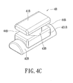
- Fig. 4C is a perspective view of the positioning piece according to a further embodiment of the present invention.
- Fig. 5 is a cross-sectional view showing the line L-L in Fig. 2 ;
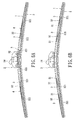
- Fig. 6A is a front view of the warping piece according to another embodiment of the present invention.
- Fig. 6B is a front view of the warping piece according to a further embodiment of the present invention.
- the present invention is to provide a windshield wiper.
- a driving arm 24 exerting an action force on the windshield wiper, the windshield wiper can be attached to the windshield of a car.
- the driving arm 24 drives the windshield wiper to swing repeatedly on the windshield.
- the windshield wiper includes a flexible support 1, a connecting piece 2, two warping pieces 3, two positioning pieces 4, and a windshield wiper blade 5.
- the flexible support 1 is shaped as an elongate strip and has a Yang Module of 50 ⁇ 350GPa. The middle portion and end portion of the flexible support 1 have different curvatures.
- the top surface of the flexible support 1 is provided with two pairs of fastening holes 11, two fasteners 12 and two positioning holes 13 ( Figs. 2 and 3 ).
- the two pairs of fastening holes 11 are provided on both end of the top surface of the flexible support 1 and penetrate to the bottom surface of the flexible support 1.
- the fastener 12 has two first locking pieces 121 that are symmetrical to each other and separated from each other. The two first fastening pieces 121 are inserted into the two pairs of fastening holes 11 and are fastened to the windshield wiper blade 5.
- the positioning holes 13 are provided in the center of the middle portion and the end portion, which are located on the top surface of the flexible support 1 and penetrate to the bottom surface of the flexible support 1.
- the flexible support 1 bears the action force to generate a flexible deformation, so that the external force is uniformly distributed on the flexible support 1 so as to make the windshield wiper be attached tightly to the windshield.
- the middle portion and the end portion of the flexible support 1 have different curvatures, the windshield wiper can be attached more tightly on the windshield, thereby increasing its effect of wiping rains.
- the curvature, length, width, and thickness of the flexible support 1 are dependent on the contact force of the windshield wiper, and thus they can be modified according to practice demands.
- the curvature of the middle portion of the flexible support 1 is smaller than that of the end portion, wherein the flexible support 1 is 500mm in length, 14mm in width, 0.8mm in thickness, but these dimensions are not limited thereto.
- the connecting piece 2 is disposed on the top surface of the flexible support 1.
- the connecting piece 2 has a pivoting portion 21 and a fixing portion 22.
- the fixing portion 22 has two symmetrical side plates 221 and a bottom plate 222.
- the side plates 221 are separated from each other and arranged in parallel on the bottom plate 222.
- the side plates 221 and the bottom plate 222 are arranged vertically to be integrated into one unit.
- the side plates 221 and the bottom plate 222 enclose to form an accommodating chamber 23. Both side edges of the bottom plate 222 have two fixing pieces 2221 respectively.
- the fixing piece 2221 is fixedly connected to the flexible support 1 for fixing the connecting piece 2 to the flexible support 1. Both ends of the pivoting portion 21 are fixedly connected to the two side plates 221.
- the pivoting portion 21 is pivoted to the driving arm 2 that is disposed in the accommodating chamber 23.
- the driving arm 24 can exert an action force on the connecting piece 2, so that the windshield wiper can be attached to the windshield.
- the driving arm 24 drives the windshield wiper to swing repeatedly on the windshield, thereby wiping off rains on the windshield.
- Each of the warping pieces 3 has a positioning portion 31, two elastic portions 32, and two reinforcing ribs 33.
- the positioning portion 31 abuts the bottom surface of the flexible support 1. Both ends of the positioning portion 31 extend downwards to form the elastic portion 32.
- the positioning portion 31 and the elastic portion 32 are shaped as a seesaw respectively ( Fig. 2A ), so that the elastic portion 32 swings up-and-down by means of using the positioning portion 31 as a fulcrum.
- the reinforcing ribs 33 are provided on both side edges of the positioning portion 31 and the elastic portion 32, thereby increasing the strength of the warping piece 3.
- the positioning portion 32 and the elastic portion 32 are integrally formed into one unit.
- the positioning portion 31 is provided with a through-hole 311.
- Each of the elastic portions 32 has two second locking pieces 321 that are symmetrical to each other and separated from each other.
- the second locking pieces 321 are fastened to the windshield wiper blade 5.
- the warping piece 3 whose elastic portion 32 swings up-and-down by means of using the positioning portion 31 as a fulcrum generates a corresponding deformation, so that the degree of curvature of the windshield wiper blade 5 fastened to the second locking pieces 321 can be changed with the degree of curvature of the windshield.
- the windshield wiper blade 5 can be attached more tightly to the windshield.
- the warping piece 3 is deformed by an external action force, which in turn changes the degree of curvature of the windshield wiper blade 5.
- the curvature of the windshield wiper blade 5 also corresponds to the deformation of the warping piece 3.
- the warping piece 3 is partially provided on the flexible support 1, thereby avoiding the problem that portions of the windshield wiper blade 5 cannot be attached to the windshield and increasing its effect of wiping rains. Furthermore, the positions on which the warping piece 3 may be provided on the flexible support 1 and the number of the warping pieces 3 can be varied according to practical demands. In the present embodiment, two warping pieces 3 are provided, and the positions of the warping pieces 3 correspond to those of the positioning holes 13 respectively.
- Each of the positioning pieces 4 has a top portion 41, a base portion 42, and a beam portion 43 ( Fig. 4A ).
- the top portion 41 is shaped as an elongate strip.
- the base portion 42 is slightly shaped as an elongate strip.
- the middle of the base portion 42 is provided with a flange 421.
- One end of the beam portion 43 is fixedly connected to the top portion 41.
- the other end of the beam portion 43 is fixedly connected to the base portion 42, so that the top portion 41 and the base portion 42 are separated from each other and arranged in parallel on both ends of the beam portion 43.
- the middle of the beam portion 43 is provided with a partition 431.
- the partition 431 is disposed between the top portion 41 and the base portion 42 to be parallel with them.
- the top portion 41, the base portion 42, and the beam portion 43 are integrally formed into one unit.
- the top portion 41, the base portion 42, and the beam portion 43 enclose to form a pair of first positioning grooves 44 and a pair of second positioning grooves 45.
- the height of the first positioning grooves 44 corresponds to the thickness of the corresponding flexible support 1.
- the height of the second positioning groove 45 corresponds to the thickness of the positioning portion 31.
- the top portion 41 passes through the through-hole 311 of the positioning portion 31 and the positioning hole 13 of the flexible support 1 ( Fig. 3 ), and it is rotatably fastened to the top surface of the flexible support 1.
- the bottom surface of the top portion 41 and the top surface of the partition 431 abut the flexible support 1 ( Fig. 2A ).
- the flange 421 of the base portion 42 and the bottom surface of the partition 431 abut the warping piece 3, so that the flexible support 1 and the warping piece 3 are fastened to the first positioning groove 44 and the second positioning groove 45 respectively.
- the warping piece 3 is fixed to the flexible support 1.
- the positioning piece 4 allows the warping piece 3 to be assembled to the flexible support 1 rapidly and easily, thereby reducing the time for assembling the windshield wiper and facilitating the detachment thereof.
- the flexible support 1 and the warping piece 3 are fastened to the first positioning groove 44 and the second positioning groove 45 respectively, so that the warping piece 3 can be connected tightly to the flexible support 1 to provide the positioning portion 31 with a firm connection.
- the warping piece 3 is prevented from shaking due to an external force and in turn the generation of noise can be prevented.
- the windshield wiper blade 5 is prevented from shaking.
- the windshield wiper blade 5 comprises an assembling portion 51, two engaging grooves 52, a connecting portion 53, a wiping piece 54, and a reinforcing piece 55 ( Fig. 5 ). Both side faces of the assembling portion 51 are provided with an engaging groove 52 respectively.
- the engaging groove 52 corresponds to the first locking piece 121 and the second locking piece 321 ( Fig. 2 ), so that the first locking piece 121 and the second locking piece 321 are fastened in the engaging groove 52.
- the assembling portion 51 is shaped as an elongate strip of the same width.
- the bottom surface of the assembling portion 51 is connected to the top surface of the connecting portion 53.
- the bottom surface of the connecting portion 53 is connected to the top surface of the wiping piece 54.
- the assembling portion 51, the connecting portion 53, and the wiping piece 54 are integrally formed into one unit.
- the connecting portion 53 is shaped as an elongate strip of the same width.
- the width of the connecting portion 53 is smaller than that of the assembling portion 51.
- the wiping piece 54 is shaped as an elongate strip.
- the width of the top surface of the wiping piece 54 is larger than that of the connecting portion 53.
- the width of the wiping piece 54 tapers from its top surface to its bottom surface.
- the wiping piece 54 can swing laterally by means of using the connecting portion 53 as a fulcrum.
- the interior of the assembling portion 51 is coated with the reinforcing piece 55 for increasing the strength of the windshield wiper blade 5, so that the windshield wiper blade 5 and the flexible support 1 are assembled to form one unit.
- the windshield wiper blade 5 is made of soft rubber with high toughness.
- any suitable soft material with high toughness may be employed.
- the warping piece 3 can be designed into various forms.
- the number of the warping pieces 3 can be increased up to three or more ( Figs. 6A and 6B ), so that the warping pieces 3 can be distributed uniformly on the flexible support 1.
- the warping piece 3 can have a positioning portion 31 and an elastic portion 32 ( Fig. 6B ).
- the positioning portion 31 is fixed directly to the bottom surface of the flexible support 1 by means of welding, screw elements or rivets.
- each of the positioning pieces 4A has a top portion 41A, a base portion 42A, and a beam portion 43A.
- the top portion 41A is shaped as an elongate strip.
- the base portion 42A is shaped as a semi-circular post.
- One end of the beam portion 43A is fixed to the top portion 41A.
- the other end of the beam portion 43A is fixed to the base portion 42A, so that the top portion 41A, and the base portion 42A are separated from each other and disposed in parallel on both ends of the beam portion 43A.
- the top portion 41A, the base portion 42A, and the beam portion 43A are integrally formed into one unit.
- the bottom surface of the top portion 41A, the top surface of the base portion 42A, and the outer wall of the beam portion 43A enclose to form a pair of positioning grooves 44A.
- the height of the positioning groove 44A corresponds to the thicknesses of the flexible support 1 and the positioning portion 31.
- the top portion 41A passes through the through-hole 311 of the positioning portion 31 and the positioning hole 13 of the flexible support 1, and it is rotatably fastened to the top surface of the flexible support 1.
- the bottom surface of the top portion 41A abuts the top surface of the flexible support 1.
- the top surface of the base portion 42A abuts the bottom surface of the positioning portion 31 of the warping piece 3, so that the flexible support 1 and the warping piece 3 can be fastened to the positioning groove 44A.
- the warping piece 3 is fixed to the flexible support 1.
- Each of the positioning pieces 4B has a top portion 41B, a base portion 42B, and a beam portion 43B.
- the top portion 41B is shaped as an elongate strip.
- the base portion 42B is shaped as a semi-circular post.
- One end of the beam portion 43B is fixed to the top portion 41B.
- the other end of the beam portion 43B is fixed to the base portion 42B, so that the top portion 41B and the base portion 42B are separated from each other and disposed in parallel on both ends of the beam portion 43B.
- the beam portion 43B has a restricting portion 431B.
- the bottom surface of the top portion 41B, the top surface of the restricting portion 431B, and the outer wall of the beam portion 43B enclose to form a pair of positioning grooves 44B.
- the height of the positioning groove 44B corresponds to the thicknesses of the flexible support 1 and the positioning portion 31.
- the present invention has advantageous features as follows.
Landscapes
- Engineering & Computer Science (AREA)
- Mechanical Engineering (AREA)
- Cleaning Implements For Floors, Carpets, Furniture, Walls, And The Like (AREA)
- Body Structure For Vehicles (AREA)
Abstract
Description
- The present invention relates to a windshield wiper, and in particular, to a windshield wiper used in a car.
- Windshield wiper is mounted in front of the windshield of a car. With a driving arm exerting a force on the windshield wiper, the windshield wiper is attached to the windshield. The driving arm drives the windshield wiper to swing on the windshield repeatedly so as to wipe off rains thereon. Please refer to
Fig. 1 . Conventional windshield wiper includes a windshield wiper support 1a and awindshield wiper blade 2a. Thewindshield wiper blade 2a is fastened to the windshield wiper support 1a. The windshield wiper support 1a comprises a primary support 11a, twosecondary supports 12a and two fastening supports 13a. The middle of the primary support 11a has a pivot 111a for pivoting to the driving arm (not shown). Both ends of the primary support 11a have afirst pivoting portion 112a respectively for pivoting to thesecondary support 12a. The outside end of eachsecondary support 12a is provided with afirst fastening piece 121a for fastening the end of thewindshield wiper blade 2a respectively. The inside end of thesecondary support 12a has asecond pivoting portion 122a for pivoting to thefastening support 13a. Both ends of thefastening support 13a are provided with asecond fastening piece 131a respectively for fastening thewindshield wiper blade 2a. - However, the conventional windshield wiper has drawbacks as follows:
- (I) The
windshield wiper blade 2a is fastened to thesecondary support 12a and the fastening support 13a via thefirst fastening piece 121a and thesecond fastening piece 131a. The flexible deformation of thesecondary support 12a and thefastening support 13a is small. When the driving arm (not shown) drives thewindshield wiper blade 2a to swing on the windshield repeatedly, a portion of thewindshield wiper blade 2a cannot be attached to the windshield completely, which may reduce its effect of wiping rains. - (II) The primary support 11a, the
secondary support 12a and thefastening support 13a are pivoted to one another via thefirst pivoting portion 112a and thesecond pivoting portion 122a. Thus, these elements may get loosened due to the clearance fit among rigid bodies. When the windshield wiper swings on the windshield repeatedly, noise may be generated easily. Also, thewindshield wiper blade 2a may shake easily to reduce its effect of wiping rains. - Consequently, because of the above limitation resulting from the technical design of prior art, the inventor strives via real world experience and academic research to develop the present invention, which can effectively improve the limitations described above.
- The objective of the present invention is to provide a windshield wiper. With a warping piece and a positioning piece, the windshield wiper blade can be attached tightly to the windshield without shaking due to an external force. Thus, its effect of wiping rains can be increased and the generation of noise is prevented
- To achieve the above-mentioned objective, the present invention provides a windshield wiper, which includes: a flexible support with its middle portion and end portion having different curvatures, one surface of the flexible support being provided with at least two fasteners and at least one positioning holes; a connecting piece fixedly connected to one surface of the flexible support; at least one warping piece having a positioning portion and at least one elastic portion, one end of the positioning portion extending to form the elastic portion, the positioning portion abutting the flexible support, the positioning portion being provided with a through-hole, the elastic portion having at least one locking piece; at least one positioning piece passing through the through-hole and the positioning hole to be fastened to the flexible support; and a windshield wiper blade, the two fasteners being fastened to both ends of the windshield wiper blade, the locking piece being fastened to the windshield wiper blade.
- The present invention has advantageous features as follows.
- (I) Since the middle portion and the end portion of the flexible support have different curvatures, the windshield wiper can be attached more tightly to the windshield, thereby increasing its effect of wiping rains.
- (II) Depending on the variation in contact force between the windshield wiper and the windshield, the warping piece generates a corresponding deformation. Thus, when the degree of curvature of the windshield varies, the degree of curvature of the windshield wiper blade varies accordingly. The windshield wiper blade can be attached more tightly to the windshield, thereby increasing its effect of wiping rains.
- (III) In addition to correspond to the curvature of the flexible support, the curvature of the windshield wiper blade also corresponds to the deformation of the warping piece. Thus, the warping piece is partially disposed in the flexible support, so that the problem that a portion of the windshield wiper blade is not attached to the windshield is prevented. As a result, its effect of wiping rains can be increased.
- (IV) The positioning piece allows the warping piece to be assembled to the flexible support rapidly and easily, so that the time for assembling the windshield wiper is reduced and the detachment process is facilitated. Furthermore, the positioning piece allows the warping piece to be fixed tightly to the flexible support and provides a firm connection for the positioning portion. Thus, the warping piece is prevented from shaking, and the generation of noise is reduced. Also, the windshield wiper blade is prevented from shaking.
- In order to further understand the techniques, means and effects of the present invention takes for achieving the prescribed objectives, the following detailed descriptions and appended drawings are hereby referred, such that, through which, the purposes, features and aspects of the present invention can be thoroughly and concretely appreciated; however, the appended drawings are merely provided for reference and illustration, without any intention to be used for limiting the present invention.
-
Fig. 1 is a schematic view of a conventional windshield wiper; -
Fig. 2 is a front view of a windshield wiper according to the present invention; -
Fig. 2A is a front view of a warping piece and a positioning piece according to the present invention; -
Fig. 3 is a partial top view of the windshield wiper according to the present invention; -
Fig. 4A is a perspective view of the positioning piece according to the present invention; -
Fig. 4B is a perspective view of the positioning piece according to another embodiment of the present invention; -
Fig. 4C is a perspective view of the positioning piece according to a further embodiment of the present invention; and -
Fig. 5 is a cross-sectional view showing the line L-L inFig. 2 ; -
Fig. 6A is a front view of the warping piece according to another embodiment of the present invention; and -
Fig. 6B is a front view of the warping piece according to a further embodiment of the present invention. - Referring now to
Figs. 2 ,2A , and3 . The present invention is to provide a windshield wiper. With adriving arm 24 exerting an action force on the windshield wiper, the windshield wiper can be attached to the windshield of a car. The drivingarm 24 drives the windshield wiper to swing repeatedly on the windshield. The windshield wiper includes aflexible support 1, a connectingpiece 2, two warpingpieces 3, twopositioning pieces 4, and awindshield wiper blade 5. - The
flexible support 1 is shaped as an elongate strip and has a Yang Module of 50∼350GPa. The middle portion and end portion of theflexible support 1 have different curvatures. The top surface of theflexible support 1 is provided with two pairs of fastening holes 11, twofasteners 12 and two positioning holes 13 (Figs. 2 and3 ). The two pairs of fastening holes 11 are provided on both end of the top surface of theflexible support 1 and penetrate to the bottom surface of theflexible support 1. Thefastener 12 has twofirst locking pieces 121 that are symmetrical to each other and separated from each other. The twofirst fastening pieces 121 are inserted into the two pairs of fastening holes 11 and are fastened to thewindshield wiper blade 5. The positioning holes 13 are provided in the center of the middle portion and the end portion, which are located on the top surface of theflexible support 1 and penetrate to the bottom surface of theflexible support 1. When the windshield wiper is subjected to an external force, theflexible support 1 bears the action force to generate a flexible deformation, so that the external force is uniformly distributed on theflexible support 1 so as to make the windshield wiper be attached tightly to the windshield. However, since the middle portion and the end portion of theflexible support 1 have different curvatures, the windshield wiper can be attached more tightly on the windshield, thereby increasing its effect of wiping rains. Furthermore, the curvature, length, width, and thickness of theflexible support 1 are dependent on the contact force of the windshield wiper, and thus they can be modified according to practice demands. In the present embodiment, the curvature of the middle portion of theflexible support 1 is smaller than that of the end portion, wherein theflexible support 1 is 500mm in length, 14mm in width, 0.8mm in thickness, but these dimensions are not limited thereto. - The connecting
piece 2 is disposed on the top surface of theflexible support 1. The connectingpiece 2 has a pivotingportion 21 and a fixingportion 22. The fixingportion 22 has twosymmetrical side plates 221 and abottom plate 222. Theside plates 221 are separated from each other and arranged in parallel on thebottom plate 222. Theside plates 221 and thebottom plate 222 are arranged vertically to be integrated into one unit. Theside plates 221 and thebottom plate 222 enclose to form anaccommodating chamber 23. Both side edges of thebottom plate 222 have two fixingpieces 2221 respectively. Thefixing piece 2221 is fixedly connected to theflexible support 1 for fixing the connectingpiece 2 to theflexible support 1. Both ends of the pivotingportion 21 are fixedly connected to the twoside plates 221. The pivotingportion 21 is pivoted to the drivingarm 2 that is disposed in theaccommodating chamber 23. The drivingarm 24 can exert an action force on the connectingpiece 2, so that the windshield wiper can be attached to the windshield. The drivingarm 24 drives the windshield wiper to swing repeatedly on the windshield, thereby wiping off rains on the windshield. - Each of the warping
pieces 3 has apositioning portion 31, twoelastic portions 32, and two reinforcingribs 33. The positioningportion 31 abuts the bottom surface of theflexible support 1. Both ends of thepositioning portion 31 extend downwards to form theelastic portion 32. The positioningportion 31 and theelastic portion 32 are shaped as a seesaw respectively (Fig. 2A ), so that theelastic portion 32 swings up-and-down by means of using thepositioning portion 31 as a fulcrum. The reinforcingribs 33 are provided on both side edges of thepositioning portion 31 and theelastic portion 32, thereby increasing the strength of thewarping piece 3. The positioningportion 32 and theelastic portion 32 are integrally formed into one unit. The positioningportion 31 is provided with a through-hole 311. Each of theelastic portions 32 has twosecond locking pieces 321 that are symmetrical to each other and separated from each other. Thesecond locking pieces 321 are fastened to thewindshield wiper blade 5. When the windshield wiper swings on the windshield, the positions on which the windshield wiper is attached to the windshield changes with time, so that thewindshield wiper blade 5 can contact the portions of windshield having different degrees of curvature. As a result, the contact force between thewindshield wiper blade 5 and the windshield also changes with time. Further, according to various contact forces, thewarping piece 3 whoseelastic portion 32 swings up-and-down by means of using thepositioning portion 31 as a fulcrum generates a corresponding deformation, so that the degree of curvature of thewindshield wiper blade 5 fastened to thesecond locking pieces 321 can be changed with the degree of curvature of the windshield. Thus, thewindshield wiper blade 5 can be attached more tightly to the windshield. Furthermore, thewarping piece 3 is deformed by an external action force, which in turn changes the degree of curvature of thewindshield wiper blade 5. As a result, in addition to correspond to the curvature of theflexible support 1, the curvature of thewindshield wiper blade 5 also corresponds to the deformation of thewarping piece 3. Thus, thewarping piece 3 is partially provided on theflexible support 1, thereby avoiding the problem that portions of thewindshield wiper blade 5 cannot be attached to the windshield and increasing its effect of wiping rains. Furthermore, the positions on which thewarping piece 3 may be provided on theflexible support 1 and the number of the warpingpieces 3 can be varied according to practical demands. In the present embodiment, two warpingpieces 3 are provided, and the positions of the warpingpieces 3 correspond to those of the positioning holes 13 respectively. - Each of the
positioning pieces 4 has atop portion 41, abase portion 42, and a beam portion 43 (Fig. 4A ). Thetop portion 41 is shaped as an elongate strip. Thebase portion 42 is slightly shaped as an elongate strip. The middle of thebase portion 42 is provided with aflange 421. One end of thebeam portion 43 is fixedly connected to thetop portion 41. The other end of thebeam portion 43 is fixedly connected to thebase portion 42, so that thetop portion 41 and thebase portion 42 are separated from each other and arranged in parallel on both ends of thebeam portion 43. The middle of thebeam portion 43 is provided with apartition 431. Thepartition 431 is disposed between thetop portion 41 and thebase portion 42 to be parallel with them. Thetop portion 41, thebase portion 42, and thebeam portion 43 are integrally formed into one unit. Thetop portion 41, thebase portion 42, and thebeam portion 43 enclose to form a pair offirst positioning grooves 44 and a pair ofsecond positioning grooves 45. The height of thefirst positioning grooves 44 corresponds to the thickness of the correspondingflexible support 1. The height of thesecond positioning groove 45 corresponds to the thickness of thepositioning portion 31. Thetop portion 41 passes through the through-hole 311 of thepositioning portion 31 and thepositioning hole 13 of the flexible support 1 (Fig. 3 ), and it is rotatably fastened to the top surface of theflexible support 1. The bottom surface of thetop portion 41 and the top surface of thepartition 431 abut the flexible support 1 (Fig. 2A ). Theflange 421 of thebase portion 42 and the bottom surface of thepartition 431 abut thewarping piece 3, so that theflexible support 1 and thewarping piece 3 are fastened to thefirst positioning groove 44 and thesecond positioning groove 45 respectively. Thewarping piece 3 is fixed to theflexible support 1. Thepositioning piece 4 allows thewarping piece 3 to be assembled to theflexible support 1 rapidly and easily, thereby reducing the time for assembling the windshield wiper and facilitating the detachment thereof. Theflexible support 1 and thewarping piece 3 are fastened to thefirst positioning groove 44 and thesecond positioning groove 45 respectively, so that thewarping piece 3 can be connected tightly to theflexible support 1 to provide thepositioning portion 31 with a firm connection. Thus, thewarping piece 3 is prevented from shaking due to an external force and in turn the generation of noise can be prevented. Also, thewindshield wiper blade 5 is prevented from shaking. - Both ends of the
windshield wiper blade 5 are fastened to thefasteners 12 of theflexible support 1, so that the curvature of thewindshield wiper blade 5 substantially coincides with that of theflexible support 1. Thewindshield wiper blade 5 comprises an assemblingportion 51, two engaginggrooves 52, a connectingportion 53, a wipingpiece 54, and a reinforcing piece 55 (Fig. 5 ). Both side faces of the assemblingportion 51 are provided with an engaginggroove 52 respectively. The engaginggroove 52 corresponds to thefirst locking piece 121 and the second locking piece 321 (Fig. 2 ), so that thefirst locking piece 121 and thesecond locking piece 321 are fastened in the engaginggroove 52. The assemblingportion 51 is shaped as an elongate strip of the same width. The bottom surface of the assemblingportion 51 is connected to the top surface of the connectingportion 53. The bottom surface of the connectingportion 53 is connected to the top surface of the wipingpiece 54. The assemblingportion 51, the connectingportion 53, and thewiping piece 54 are integrally formed into one unit. The connectingportion 53 is shaped as an elongate strip of the same width. The width of the connectingportion 53 is smaller than that of the assemblingportion 51. The wipingpiece 54 is shaped as an elongate strip. The width of the top surface of the wipingpiece 54 is larger than that of the connectingportion 53. The width of the wipingpiece 54 tapers from its top surface to its bottom surface. Thus, when the bottom surface of the wipingpiece 54 is subjected to a lateral force, the wipingpiece 54 can swing laterally by means of using the connectingportion 53 as a fulcrum. The interior of the assemblingportion 51 is coated with the reinforcingpiece 55 for increasing the strength of thewindshield wiper blade 5, so that thewindshield wiper blade 5 and theflexible support 1 are assembled to form one unit. In general, thewindshield wiper blade 5 is made of soft rubber with high toughness. However, in the present invention, any suitable soft material with high toughness may be employed. - The
warping piece 3 can be designed into various forms. The number of the warpingpieces 3 can be increased up to three or more (Figs. 6A and 6B ), so that the warpingpieces 3 can be distributed uniformly on theflexible support 1. Alternatively, thewarping piece 3 can have apositioning portion 31 and an elastic portion 32 (Fig. 6B ). The positioningportion 31 is fixed directly to the bottom surface of theflexible support 1 by means of welding, screw elements or rivets. - Furthermore, the
positioning piece 4A can be designed into various forms. Please refer toFig. 4B . Each of thepositioning pieces 4A has atop portion 41A, abase portion 42A, and abeam portion 43A. Thetop portion 41A is shaped as an elongate strip. Thebase portion 42A is shaped as a semi-circular post. One end of thebeam portion 43A is fixed to thetop portion 41A. The other end of thebeam portion 43A is fixed to thebase portion 42A, so that thetop portion 41A, and thebase portion 42A are separated from each other and disposed in parallel on both ends of thebeam portion 43A. Thetop portion 41A, thebase portion 42A, and thebeam portion 43A are integrally formed into one unit. The bottom surface of thetop portion 41A, the top surface of thebase portion 42A, and the outer wall of thebeam portion 43A enclose to form a pair ofpositioning grooves 44A. The height of thepositioning groove 44A corresponds to the thicknesses of theflexible support 1 and thepositioning portion 31. Thetop portion 41A passes through the through-hole 311 of thepositioning portion 31 and thepositioning hole 13 of theflexible support 1, and it is rotatably fastened to the top surface of theflexible support 1. The bottom surface of thetop portion 41A abuts the top surface of theflexible support 1. The top surface of thebase portion 42A abuts the bottom surface of thepositioning portion 31 of thewarping piece 3, so that theflexible support 1 and thewarping piece 3 can be fastened to thepositioning groove 44A. Thewarping piece 3 is fixed to theflexible support 1. - Furthermore, please refer to
Fig. 4C . Each of thepositioning pieces 4B has atop portion 41B, abase portion 42B, and abeam portion 43B. Thetop portion 41B is shaped as an elongate strip. Thebase portion 42B is shaped as a semi-circular post. One end of thebeam portion 43B is fixed to thetop portion 41B. The other end of thebeam portion 43B is fixed to thebase portion 42B, so that thetop portion 41B and thebase portion 42B are separated from each other and disposed in parallel on both ends of thebeam portion 43B. Thebeam portion 43B has a restrictingportion 431B. The bottom surface of thetop portion 41B, the top surface of the restrictingportion 431B, and the outer wall of thebeam portion 43B enclose to form a pair ofpositioning grooves 44B. The height of thepositioning groove 44B corresponds to the thicknesses of theflexible support 1 and thepositioning portion 31. When theflexible support 1 and thewarping piece 3 are fastened to thepositioning groove 44B, the restrictingportion 431B abuts thewarping piece 3, so that thewarping piece 3 can be fixed to theflexible support 1 more firmly. Via this arrangement, when theelastic portion 32 swings up-and-down by using thepositioning portion 31 as a fulcrum, its stability can be increased. - The present invention has advantageous features as follows.
- (I) Since the middle portion and the end portion of the
flexible support 1 have different curvatures, the windshield wiper can be attached more tightly to the windshield, thereby increasing its effect of wiping rains. - (II) Depending on the variation in contact force between the windshield wiper and the windshield, the
warping piece 3 generates a corresponding deformation. Thus, when the degree of curvature of the windshield varies, the degree of curvature of thewindshield wiper blade 5 varies accordingly. Thewindshield wiper blade 5 can be attached more tightly to the windshield, thereby increasing its effect of wiping rains. - (III) In addition to correspond to the curvature of the
flexible support 1, the curvature of thewindshield wiper blade 5 also corresponds to the deformation of thewarping piece 3. Thus, thewarping piece 3 is partially disposed in the flexible support, so that the problem that a portion of thewindshield wiper blade 5 is not attached to the windshield can be prevented. As a result, its effect of wiping rains can be increased. - (IV) The
positioning piece 4 allows thewarping piece 3 to be assembled to theflexible support 1 rapidly and easily, so that the time for assembling the windshield wiper is reduced and the detachment process is facilitated. Furthermore, thepositioning piece 4 allows thewarping piece 3 to be fixed tightly to theflexible support 1 and provides a firm connection for thepositioning portion 31. Thus, thewarping piece 3 can be prevented from shaking, and the generation of noise is reduced. Also, thewindshield wiper blade 5 can be prevented from shaking. - The above-mentioned descriptions represent merely the preferred embodiment of the present invention, without any intention to limit the scope of the present invention thereto. Various equivalent changes, alternations or modifications based on the claims of present invention are all consequently viewed as being embraced by the scope of the present invention.
Claims (14)
- A windshield wiper, comprising:a flexible support with its middle portion and end portion having different curvatures, one surface of the flexible support being provided with at least two fasteners and at least one positioning hole;a connecting piece fixedly connected to one surface of the flexible support;at least one warping piece, the warping piece having a positioning portion and at least one elastic portion, an end of the positioning portion extending to form the elastic portion, the positioning portion abutting the flexible support, the positioning portion being provided with a through-hole, the elastic portion having at least one locking piece;at least one positioning piece passing through the through-hole and the positioning hole to be fastened to the flexible support; anda windshield wiper blade, the two fasteners being fastened to both ends of the windshield wiper blade, the locking pieces being fastened to the windshield wiper blade.
- The windshield wiper according to claim 1, wherein the curvature of the middle portion of the flexible support is smaller than that of its end portion.
- The windshield wiper according to claim 1, wherein the connecting piece has a pivoting portion and a fixing portion, the fixing portion has two symmetrical side plates and a bottom plate, the two side plates are separated from each other and arranged in parallel on the bottom plate, two side edges of the bottom plate have two fixing pieces respectively, the fixing pieces are fixed to the flexible support.
- The windshield wiper according to claim 1, wherein the warping piece further comprises at least one reinforcing rib, the reinforcing rib is provided on the positioning portion and both side edges of the elastic portion.
- The windshield wiper according to claim 1, wherein the positioning piece has a top portion, a base portion, and a beam portion, one end of the beam portion is fixed to the top portion, the other end of the beam portion is fixed to the base portion, the top portion and the base portion are separated from each other and arranged in parallel on both ends of the beam portion.
- The windshield wiper according to claim 5, wherein the base portion is provided with a flange, the beam portion is provided with a partition, the partition is arranged between the top portion and the base portion and is in parallel with them, the top portion and one surface of the partition abut the flexible support, the flange and the other surface of the partition abut the warping piece, the top portion, the base portion, and the beam portion enclose a first positioning groove and a second positioning groove, the height of the first positioning groove corresponds to the thickness of the flexible support, the height of the second positioning groove corresponds to the thickness of the positioning portion, the flexible support is fastened to the first positioning groove, the warping piece is fastened to the second positioning groove.
- The windshield wiper according to claim 5, wherein the top portion is shaped as an elongate piece, the base portion is shaped as a semi-circular post, the top portion abuts the top surface of the flexible support, the base portion abuts the bottom surface of the positioning portion of the warping piece, the top portion, the base portion, and the beam portion enclose a positioning groove, the height of the positioning groove corresponds to the thickness of the flexible support and the thickness of the positioning portion, the flexible support and the warping piece are fastened to the positioning groove.
- The windshield wiper according to claim 5, wherein the top portion is shaped as an elongate strip, the base portion is shaped as a semi-circular post, the beam portion has a restricting portion, the top portion abuts the top surface of the flexible support, the restricting portion abuts the warping piece, the top portion, the restricting portion, and the beam portion enclose a positioning groove, the height of the positioning groove corresponds to the thickness of the flexible support and the thickness of the positioning portion, the flexible support and the warping piece are fastened to the positioning groove.
- The windshield wiper according to claim 1, wherein the windshield wiper blade comprises an assembling portion, two engaging grooves, a connecting portion, a wiping piece, and a reinforcing piece, the two engaging grooves are provided on both side surfaces of the assembling portion, the two fasteners and the locking pieces are fastened to the engaging grooves, the bottom surface of the assembling portion is connected to the top surface of the connecting portion, the bottom surface of the connecting portion is connected to the top surface of the wiping piece, the width of the connecting portion is smaller than the width of the assembling portion, the width of the top surface of the wiping piece is larger than that of the connecting portion, the width of the wiping piece tapers from its top surface to its bottom surface, the assembling portion covers the reinforcing piece.
- A windshield wiper, comprising:a flexible support with its middle portion and end portion having different curvatures, one surface of the flexible support being provided with at least two fasteners;a connecting piece fixedly connected to one surface of the flexible support;at least one warping piece, the warping piece having a positioning portion and at least one elastic portion, an end of the positioning portion extending to form the elastic portion, the positioning portion abutting the bottom surface of the flexible support, the elastic portion having at least one locking piece; anda windshield wiper blade, the two fasteners being fastened to both ends of the windshield wiper blade, the locking pieces being fastened to the windshield wiper blade.
- The windshield wiper according to claim 10, wherein the curvature of the middle portion of the flexible support is smaller than that of its end portion.
- The windshield wiper according to claim 10, wherein the warping piece further comprises at least one reinforcing rib, the reinforcing rib is arranged to the positioning portion and two side edges of the elastic portion.
- The windshield wiper according to claim 10, wherein the positioning portion is connected to the flexible support by means of welding, screws or rivets.
- The windshield wiper according to claim 10, wherein the windshield wiper blade comprises an assembling portion, two engaging grooves, a connecting portion, a wiping piece, and a reinforcing piece, the two engaging grooves are provided on both side surfaces of the assembling portion, the two fasteners and the locking pieces are fastened to the engaging grooves, the bottom surface of the assembling portion is connected to the top surface of the connecting portion, the bottom surface of the connecting portion is connected to the top surface of the wiping piece, the width of the connecting portion is smaller than that of the assembling portion, the width of the top surface of the wiping piece is larger than that of the connecting portion, the width of the wiping piece tapers from its top surface to its bottom surface, the assembling portion covers the reinforcing piece.
Priority Applications (2)
| Application Number | Priority Date | Filing Date | Title |
|---|---|---|---|
| PL09155335T PL2230139T3 (en) | 2009-03-17 | 2009-03-17 | Windshield wiper |
| EP09155335.4A EP2230139B1 (en) | 2009-03-17 | 2009-03-17 | Windshield wiper |
Applications Claiming Priority (1)
| Application Number | Priority Date | Filing Date | Title |
|---|---|---|---|
| EP09155335.4A EP2230139B1 (en) | 2009-03-17 | 2009-03-17 | Windshield wiper |
Publications (2)
| Publication Number | Publication Date |
|---|---|
| EP2230139A1 true EP2230139A1 (en) | 2010-09-22 |
| EP2230139B1 EP2230139B1 (en) | 2014-05-07 |
Family
ID=40886262
Family Applications (1)
| Application Number | Title | Priority Date | Filing Date |
|---|---|---|---|
| EP09155335.4A Not-in-force EP2230139B1 (en) | 2009-03-17 | 2009-03-17 | Windshield wiper |
Country Status (2)
| Country | Link |
|---|---|
| EP (1) | EP2230139B1 (en) |
| PL (1) | PL2230139T3 (en) |
Cited By (4)
| Publication number | Priority date | Publication date | Assignee | Title |
|---|---|---|---|---|
| US8261405B2 (en) | 2009-05-07 | 2012-09-11 | Kcw Corporation | Wiper blade assembly having rotatable auxiliary beam |
| US11447102B1 (en) * | 2021-06-24 | 2022-09-20 | Danyang Hurst Auto Parts Co., Ltd. | Adaptive adjustment windshield wiper |
| CN115431926A (en) * | 2021-06-03 | 2022-12-06 | 丹阳镇威汽配有限公司 | Assembly structure of multi-stage wiper |
| CN115431925A (en) * | 2021-06-02 | 2022-12-06 | 东莞山多力汽车配件有限公司 | wipers |
Citations (5)
| Publication number | Priority date | Publication date | Assignee | Title |
|---|---|---|---|---|
| US5485650A (en) * | 1992-10-23 | 1996-01-23 | Adriaan Retief Swanepoel | Windscreen wiper with elongated, curved backbone |
| FR2774341A1 (en) | 1998-01-30 | 1999-08-06 | Valeo Systemes Dessuyage | Automobile windscreen wiper blade with improved structure |
| US20070186366A1 (en) * | 2006-02-15 | 2007-08-16 | Alley David J | Windshield wiper and scraper |
| CA2585208A1 (en) * | 2007-04-18 | 2008-10-18 | Shih-Hsien Huang | Vehicle windshield wiper for rain and snow dual purpose |
| US20080295273A1 (en) * | 2007-06-01 | 2008-12-04 | Sally Lin | Non-bracket windshield wiper |
-
2009
- 2009-03-17 PL PL09155335T patent/PL2230139T3/en unknown
- 2009-03-17 EP EP09155335.4A patent/EP2230139B1/en not_active Not-in-force
Patent Citations (5)
| Publication number | Priority date | Publication date | Assignee | Title |
|---|---|---|---|---|
| US5485650A (en) * | 1992-10-23 | 1996-01-23 | Adriaan Retief Swanepoel | Windscreen wiper with elongated, curved backbone |
| FR2774341A1 (en) | 1998-01-30 | 1999-08-06 | Valeo Systemes Dessuyage | Automobile windscreen wiper blade with improved structure |
| US20070186366A1 (en) * | 2006-02-15 | 2007-08-16 | Alley David J | Windshield wiper and scraper |
| CA2585208A1 (en) * | 2007-04-18 | 2008-10-18 | Shih-Hsien Huang | Vehicle windshield wiper for rain and snow dual purpose |
| US20080295273A1 (en) * | 2007-06-01 | 2008-12-04 | Sally Lin | Non-bracket windshield wiper |
Cited By (4)
| Publication number | Priority date | Publication date | Assignee | Title |
|---|---|---|---|---|
| US8261405B2 (en) | 2009-05-07 | 2012-09-11 | Kcw Corporation | Wiper blade assembly having rotatable auxiliary beam |
| CN115431925A (en) * | 2021-06-02 | 2022-12-06 | 东莞山多力汽车配件有限公司 | wipers |
| CN115431926A (en) * | 2021-06-03 | 2022-12-06 | 丹阳镇威汽配有限公司 | Assembly structure of multi-stage wiper |
| US11447102B1 (en) * | 2021-06-24 | 2022-09-20 | Danyang Hurst Auto Parts Co., Ltd. | Adaptive adjustment windshield wiper |
Also Published As
| Publication number | Publication date |
|---|---|
| EP2230139B1 (en) | 2014-05-07 |
| PL2230139T3 (en) | 2014-11-28 |
Similar Documents
| Publication | Publication Date | Title |
|---|---|---|
| US20100236008A1 (en) | Windshield wiper | |
| US8650701B2 (en) | Connecting assembly for windshield wiper | |
| KR101052268B1 (en) | Wiper Blade Assembly with Rotating Auxiliary Beam | |
| US8028368B2 (en) | Windshield wiper | |
| US9162649B2 (en) | Windshield wiper | |
| US9032585B2 (en) | Windshield wiper assembly having a body made of spring steel | |
| KR101105340B1 (en) | How to Assemble Metal Clamps and Body Springs for Automotive Wiper Blades | |
| CN104114421B (en) | Wiping device and its manufacture method | |
| US8181308B2 (en) | Wiper for vehicle having improved assembling efficiency and reduced weight | |
| US9714008B2 (en) | Flat wiper blade and coupling method thereof | |
| EP2230139A1 (en) | Windshield wiper | |
| CA2569977A1 (en) | Wiper blade | |
| US20060000045A1 (en) | Wiper structure | |
| JP2013023209A (en) | Wiper blade | |
| US20120079669A1 (en) | Fixing base for a windshield wiper | |
| CN104284816A (en) | Windscreen wiper device | |
| US9862356B2 (en) | Wiper blade | |
| JPWO2004012967A1 (en) | Wiper blade | |
| KR101693832B1 (en) | Wiper Blade | |
| CN103347747B (en) | Windscreen wiper device | |
| JP3160871U (en) | Flat blade wiper for vehicle | |
| JP2002370622A (en) | Wiper blade | |
| US20080028564A1 (en) | Wiper blade support structure | |
| WO2018101177A1 (en) | Wiper blade | |
| JP3151509U (en) | Wiper structure |
Legal Events
| Date | Code | Title | Description |
|---|---|---|---|
| PUAI | Public reference made under article 153(3) epc to a published international application that has entered the european phase |
Free format text: ORIGINAL CODE: 0009012 |
|
| AK | Designated contracting states |
Kind code of ref document: A1 Designated state(s): AT BE BG CH CY CZ DE DK EE ES FI FR GB GR HR HU IE IS IT LI LT LU LV MC MK MT NL NO PL PT RO SE SI SK TR |
|
| AX | Request for extension of the european patent |
Extension state: AL BA RS |
|
| 17P | Request for examination filed |
Effective date: 20110121 |
|
| 17Q | First examination report despatched |
Effective date: 20110216 |
|
| AKX | Designation fees paid |
Designated state(s): AT BE BG CH CY CZ DE DK EE ES FI FR GB GR HR HU IE IS IT LI LT LU LV MC MK MT NL NO PL PT RO SE SI SK TR |
|
| RIN1 | Information on inventor provided before grant (corrected) |
Inventor name: YANG, CHIH-MING Inventor name: CHANG, CHUAN-CHIH Inventor name: CHAO, CHIN-CHEN |
|
| RIN1 | Information on inventor provided before grant (corrected) |
Inventor name: CHAO, CHIN-CHEN Inventor name: CHANG, CHUAN-CHIH Inventor name: YANG, CHIH-MING |
|
| GRAP | Despatch of communication of intention to grant a patent |
Free format text: ORIGINAL CODE: EPIDOSNIGR1 |
|
| INTG | Intention to grant announced |
Effective date: 20140116 |
|
| GRAS | Grant fee paid |
Free format text: ORIGINAL CODE: EPIDOSNIGR3 |
|
| GRAA | (expected) grant |
Free format text: ORIGINAL CODE: 0009210 |
|
| AK | Designated contracting states |
Kind code of ref document: B1 Designated state(s): AT BE BG CH CY CZ DE DK EE ES FI FR GB GR HR HU IE IS IT LI LT LU LV MC MK MT NL NO PL PT RO SE SI SK TR |
|
| REG | Reference to a national code |
Ref country code: GB Ref legal event code: FG4D |
|
| REG | Reference to a national code |
Ref country code: AT Ref legal event code: REF Ref document number: 666381 Country of ref document: AT Kind code of ref document: T Effective date: 20140515 |
|
| REG | Reference to a national code |
Ref country code: IE Ref legal event code: FG4D |
|
| REG | Reference to a national code |
Ref country code: DE Ref legal event code: R096 Ref document number: 602009023801 Country of ref document: DE Effective date: 20140618 |
|
| REG | Reference to a national code |
Ref country code: AT Ref legal event code: MK05 Ref document number: 666381 Country of ref document: AT Kind code of ref document: T Effective date: 20140507 |
|
| REG | Reference to a national code |
Ref country code: NL Ref legal event code: VDEP Effective date: 20140507 |
|
| REG | Reference to a national code |
Ref country code: LT Ref legal event code: MG4D |
|
| PG25 | Lapsed in a contracting state [announced via postgrant information from national office to epo] |
Ref country code: IS Free format text: LAPSE BECAUSE OF FAILURE TO SUBMIT A TRANSLATION OF THE DESCRIPTION OR TO PAY THE FEE WITHIN THE PRESCRIBED TIME-LIMIT Effective date: 20140907 Ref country code: GR Free format text: LAPSE BECAUSE OF FAILURE TO SUBMIT A TRANSLATION OF THE DESCRIPTION OR TO PAY THE FEE WITHIN THE PRESCRIBED TIME-LIMIT Effective date: 20140808 Ref country code: LT Free format text: LAPSE BECAUSE OF FAILURE TO SUBMIT A TRANSLATION OF THE DESCRIPTION OR TO PAY THE FEE WITHIN THE PRESCRIBED TIME-LIMIT Effective date: 20140507 Ref country code: CY Free format text: LAPSE BECAUSE OF FAILURE TO SUBMIT A TRANSLATION OF THE DESCRIPTION OR TO PAY THE FEE WITHIN THE PRESCRIBED TIME-LIMIT Effective date: 20140507 Ref country code: NO Free format text: LAPSE BECAUSE OF FAILURE TO SUBMIT A TRANSLATION OF THE DESCRIPTION OR TO PAY THE FEE WITHIN THE PRESCRIBED TIME-LIMIT Effective date: 20140807 Ref country code: FI Free format text: LAPSE BECAUSE OF FAILURE TO SUBMIT A TRANSLATION OF THE DESCRIPTION OR TO PAY THE FEE WITHIN THE PRESCRIBED TIME-LIMIT Effective date: 20140507 |
|
| PG25 | Lapsed in a contracting state [announced via postgrant information from national office to epo] |
Ref country code: SE Free format text: LAPSE BECAUSE OF FAILURE TO SUBMIT A TRANSLATION OF THE DESCRIPTION OR TO PAY THE FEE WITHIN THE PRESCRIBED TIME-LIMIT Effective date: 20140507 Ref country code: ES Free format text: LAPSE BECAUSE OF FAILURE TO SUBMIT A TRANSLATION OF THE DESCRIPTION OR TO PAY THE FEE WITHIN THE PRESCRIBED TIME-LIMIT Effective date: 20140507 Ref country code: LV Free format text: LAPSE BECAUSE OF FAILURE TO SUBMIT A TRANSLATION OF THE DESCRIPTION OR TO PAY THE FEE WITHIN THE PRESCRIBED TIME-LIMIT Effective date: 20140507 Ref country code: HR Free format text: LAPSE BECAUSE OF FAILURE TO SUBMIT A TRANSLATION OF THE DESCRIPTION OR TO PAY THE FEE WITHIN THE PRESCRIBED TIME-LIMIT Effective date: 20140507 Ref country code: AT Free format text: LAPSE BECAUSE OF FAILURE TO SUBMIT A TRANSLATION OF THE DESCRIPTION OR TO PAY THE FEE WITHIN THE PRESCRIBED TIME-LIMIT Effective date: 20140507 |
|
| REG | Reference to a national code |
Ref country code: PL Ref legal event code: T3 |
|
| PG25 | Lapsed in a contracting state [announced via postgrant information from national office to epo] |
Ref country code: PT Free format text: LAPSE BECAUSE OF FAILURE TO SUBMIT A TRANSLATION OF THE DESCRIPTION OR TO PAY THE FEE WITHIN THE PRESCRIBED TIME-LIMIT Effective date: 20140908 |
|
| PG25 | Lapsed in a contracting state [announced via postgrant information from national office to epo] |
Ref country code: DK Free format text: LAPSE BECAUSE OF FAILURE TO SUBMIT A TRANSLATION OF THE DESCRIPTION OR TO PAY THE FEE WITHIN THE PRESCRIBED TIME-LIMIT Effective date: 20140507 Ref country code: BE Free format text: LAPSE BECAUSE OF FAILURE TO SUBMIT A TRANSLATION OF THE DESCRIPTION OR TO PAY THE FEE WITHIN THE PRESCRIBED TIME-LIMIT Effective date: 20140507 Ref country code: EE Free format text: LAPSE BECAUSE OF FAILURE TO SUBMIT A TRANSLATION OF THE DESCRIPTION OR TO PAY THE FEE WITHIN THE PRESCRIBED TIME-LIMIT Effective date: 20140507 Ref country code: RO Free format text: LAPSE BECAUSE OF FAILURE TO SUBMIT A TRANSLATION OF THE DESCRIPTION OR TO PAY THE FEE WITHIN THE PRESCRIBED TIME-LIMIT Effective date: 20140507 Ref country code: SK Free format text: LAPSE BECAUSE OF FAILURE TO SUBMIT A TRANSLATION OF THE DESCRIPTION OR TO PAY THE FEE WITHIN THE PRESCRIBED TIME-LIMIT Effective date: 20140507 |
|
| REG | Reference to a national code |
Ref country code: DE Ref legal event code: R097 Ref document number: 602009023801 Country of ref document: DE |
|
| PG25 | Lapsed in a contracting state [announced via postgrant information from national office to epo] |
Ref country code: NL Free format text: LAPSE BECAUSE OF FAILURE TO SUBMIT A TRANSLATION OF THE DESCRIPTION OR TO PAY THE FEE WITHIN THE PRESCRIBED TIME-LIMIT Effective date: 20140507 |
|
| PLBE | No opposition filed within time limit |
Free format text: ORIGINAL CODE: 0009261 |
|
| STAA | Information on the status of an ep patent application or granted ep patent |
Free format text: STATUS: NO OPPOSITION FILED WITHIN TIME LIMIT |
|
| 26N | No opposition filed |
Effective date: 20150210 |
|
| REG | Reference to a national code |
Ref country code: DE Ref legal event code: R097 Ref document number: 602009023801 Country of ref document: DE Effective date: 20150210 |
|
| PG25 | Lapsed in a contracting state [announced via postgrant information from national office to epo] |
Ref country code: SI Free format text: LAPSE BECAUSE OF FAILURE TO SUBMIT A TRANSLATION OF THE DESCRIPTION OR TO PAY THE FEE WITHIN THE PRESCRIBED TIME-LIMIT Effective date: 20140507 |
|
| PG25 | Lapsed in a contracting state [announced via postgrant information from national office to epo] |
Ref country code: MC Free format text: LAPSE BECAUSE OF FAILURE TO SUBMIT A TRANSLATION OF THE DESCRIPTION OR TO PAY THE FEE WITHIN THE PRESCRIBED TIME-LIMIT Effective date: 20140507 Ref country code: LU Free format text: LAPSE BECAUSE OF FAILURE TO SUBMIT A TRANSLATION OF THE DESCRIPTION OR TO PAY THE FEE WITHIN THE PRESCRIBED TIME-LIMIT Effective date: 20150317 |
|
| REG | Reference to a national code |
Ref country code: CH Ref legal event code: PL |
|
| REG | Reference to a national code |
Ref country code: IE Ref legal event code: MM4A |
|
| PG25 | Lapsed in a contracting state [announced via postgrant information from national office to epo] |
Ref country code: CH Free format text: LAPSE BECAUSE OF NON-PAYMENT OF DUE FEES Effective date: 20150331 Ref country code: LI Free format text: LAPSE BECAUSE OF NON-PAYMENT OF DUE FEES Effective date: 20150331 Ref country code: IE Free format text: LAPSE BECAUSE OF NON-PAYMENT OF DUE FEES Effective date: 20150317 |
|
| REG | Reference to a national code |
Ref country code: FR Ref legal event code: PLFP Year of fee payment: 8 |
|
| PGFP | Annual fee paid to national office [announced via postgrant information from national office to epo] |
Ref country code: IT Payment date: 20160307 Year of fee payment: 8 Ref country code: CZ Payment date: 20160224 Year of fee payment: 8 |
|
| PGFP | Annual fee paid to national office [announced via postgrant information from national office to epo] |
Ref country code: FR Payment date: 20160304 Year of fee payment: 8 Ref country code: GB Payment date: 20160329 Year of fee payment: 8 Ref country code: PL Payment date: 20160316 Year of fee payment: 8 |
|
| PGFP | Annual fee paid to national office [announced via postgrant information from national office to epo] |
Ref country code: DE Payment date: 20160330 Year of fee payment: 8 |
|
| PG25 | Lapsed in a contracting state [announced via postgrant information from national office to epo] |
Ref country code: MT Free format text: LAPSE BECAUSE OF FAILURE TO SUBMIT A TRANSLATION OF THE DESCRIPTION OR TO PAY THE FEE WITHIN THE PRESCRIBED TIME-LIMIT Effective date: 20140507 |
|
| PG25 | Lapsed in a contracting state [announced via postgrant information from national office to epo] |
Ref country code: BG Free format text: LAPSE BECAUSE OF FAILURE TO SUBMIT A TRANSLATION OF THE DESCRIPTION OR TO PAY THE FEE WITHIN THE PRESCRIBED TIME-LIMIT Effective date: 20140507 Ref country code: HU Free format text: LAPSE BECAUSE OF FAILURE TO SUBMIT A TRANSLATION OF THE DESCRIPTION OR TO PAY THE FEE WITHIN THE PRESCRIBED TIME-LIMIT; INVALID AB INITIO Effective date: 20090317 |
|
| PG25 | Lapsed in a contracting state [announced via postgrant information from national office to epo] |
Ref country code: TR Free format text: LAPSE BECAUSE OF FAILURE TO SUBMIT A TRANSLATION OF THE DESCRIPTION OR TO PAY THE FEE WITHIN THE PRESCRIBED TIME-LIMIT Effective date: 20140507 |
|
| REG | Reference to a national code |
Ref country code: DE Ref legal event code: R119 Ref document number: 602009023801 Country of ref document: DE |
|
| PG25 | Lapsed in a contracting state [announced via postgrant information from national office to epo] |
Ref country code: CZ Free format text: LAPSE BECAUSE OF NON-PAYMENT OF DUE FEES Effective date: 20170317 |
|
| GBPC | Gb: european patent ceased through non-payment of renewal fee |
Effective date: 20170317 |
|
| REG | Reference to a national code |
Ref country code: FR Ref legal event code: ST Effective date: 20171130 |
|
| PG25 | Lapsed in a contracting state [announced via postgrant information from national office to epo] |
Ref country code: DE Free format text: LAPSE BECAUSE OF NON-PAYMENT OF DUE FEES Effective date: 20171003 Ref country code: FR Free format text: LAPSE BECAUSE OF NON-PAYMENT OF DUE FEES Effective date: 20170331 |
|
| PG25 | Lapsed in a contracting state [announced via postgrant information from national office to epo] |
Ref country code: GB Free format text: LAPSE BECAUSE OF NON-PAYMENT OF DUE FEES Effective date: 20170317 Ref country code: IT Free format text: LAPSE BECAUSE OF NON-PAYMENT OF DUE FEES Effective date: 20170317 |
|
| PG25 | Lapsed in a contracting state [announced via postgrant information from national office to epo] |
Ref country code: MK Free format text: LAPSE BECAUSE OF FAILURE TO SUBMIT A TRANSLATION OF THE DESCRIPTION OR TO PAY THE FEE WITHIN THE PRESCRIBED TIME-LIMIT Effective date: 20140507 |
|
| PG25 | Lapsed in a contracting state [announced via postgrant information from national office to epo] |
Ref country code: PL Free format text: LAPSE BECAUSE OF NON-PAYMENT OF DUE FEES Effective date: 20170317 |