EP2230098A1 - Pneumatic radial tire - Google Patents
Pneumatic radial tire Download PDFInfo
- Publication number
- EP2230098A1 EP2230098A1 EP08855108A EP08855108A EP2230098A1 EP 2230098 A1 EP2230098 A1 EP 2230098A1 EP 08855108 A EP08855108 A EP 08855108A EP 08855108 A EP08855108 A EP 08855108A EP 2230098 A1 EP2230098 A1 EP 2230098A1
- Authority
- EP
- European Patent Office
- Prior art keywords
- belt
- carcass
- ply
- layer
- flexural rigidity
- Prior art date
- Legal status (The legal status is an assumption and is not a legal conclusion. Google has not performed a legal analysis and makes no representation as to the accuracy of the status listed.)
- Granted
Links
- 229920001971 elastomer Polymers 0.000 claims abstract description 59
- 239000005060 rubber Substances 0.000 claims abstract description 59
- 230000003014 reinforcing effect Effects 0.000 claims abstract description 29
- 229910000831 Steel Inorganic materials 0.000 claims abstract description 15
- 239000010959 steel Substances 0.000 claims abstract description 15
- 239000011324 bead Substances 0.000 claims description 21
- 230000015556 catabolic process Effects 0.000 abstract description 17
- 238000006731 degradation reaction Methods 0.000 abstract description 17
- 230000032798 delamination Effects 0.000 abstract description 13
- 230000003647 oxidation Effects 0.000 description 9
- 238000007254 oxidation reaction Methods 0.000 description 9
- 230000000694 effects Effects 0.000 description 6
- 238000012360 testing method Methods 0.000 description 5
- QVGXLLKOCUKJST-UHFFFAOYSA-N atomic oxygen Chemical compound [O] QVGXLLKOCUKJST-UHFFFAOYSA-N 0.000 description 3
- 229910052760 oxygen Inorganic materials 0.000 description 3
- 239000001301 oxygen Substances 0.000 description 3
- 230000000704 physical effect Effects 0.000 description 3
- 230000003993 interaction Effects 0.000 description 2
- 229920001875 Ebonite Polymers 0.000 description 1
- 230000003247 decreasing effect Effects 0.000 description 1
- 238000005259 measurement Methods 0.000 description 1
- 238000000034 method Methods 0.000 description 1
- 230000000149 penetrating effect Effects 0.000 description 1
- 230000035515 penetration Effects 0.000 description 1
- 239000000843 powder Substances 0.000 description 1
- 230000002787 reinforcement Effects 0.000 description 1
- 230000000717 retained effect Effects 0.000 description 1
- 238000000926 separation method Methods 0.000 description 1
- 238000010008 shearing Methods 0.000 description 1
- 230000002195 synergetic effect Effects 0.000 description 1
Images



Classifications
-
- B—PERFORMING OPERATIONS; TRANSPORTING
- B60—VEHICLES IN GENERAL
- B60C—VEHICLE TYRES; TYRE INFLATION; TYRE CHANGING; CONNECTING VALVES TO INFLATABLE ELASTIC BODIES IN GENERAL; DEVICES OR ARRANGEMENTS RELATED TO TYRES
- B60C9/00—Reinforcements or ply arrangement of pneumatic tyres
- B60C9/18—Structure or arrangement of belts or breakers, crown-reinforcing or cushioning layers
- B60C9/28—Structure or arrangement of belts or breakers, crown-reinforcing or cushioning layers characterised by the belt or breaker dimensions or curvature relative to carcass
-
- B—PERFORMING OPERATIONS; TRANSPORTING
- B60—VEHICLES IN GENERAL
- B60C—VEHICLE TYRES; TYRE INFLATION; TYRE CHANGING; CONNECTING VALVES TO INFLATABLE ELASTIC BODIES IN GENERAL; DEVICES OR ARRANGEMENTS RELATED TO TYRES
- B60C9/00—Reinforcements or ply arrangement of pneumatic tyres
- B60C9/18—Structure or arrangement of belts or breakers, crown-reinforcing or cushioning layers
- B60C9/20—Structure or arrangement of belts or breakers, crown-reinforcing or cushioning layers built-up from rubberised plies each having all cords arranged substantially parallel
- B60C9/2003—Structure or arrangement of belts or breakers, crown-reinforcing or cushioning layers built-up from rubberised plies each having all cords arranged substantially parallel characterised by the materials of the belt cords
- B60C9/2006—Structure or arrangement of belts or breakers, crown-reinforcing or cushioning layers built-up from rubberised plies each having all cords arranged substantially parallel characterised by the materials of the belt cords consisting of steel cord plies only
Definitions
- the present invention relates to a pneumatic radial tire using steel cords as a carcass cord and as a belt cord, which is suitable as a heavy duty radial tire and in which delamination damage between a carcass and a belt layer in final stage of wear caused by thermal degradation (oxidation degradation) is suppressed with securing the steering stability.
- Patent Literature 1 JP-A-11-222008
- Tires with this structure are excellent in both tensile strength of the cord and durability of the cord and have enough leeway in tire strength and, therefore, they have been used under a condition of high inner pressure in order to increase the loading capacity.
- Tires with the all-steel radial structure are frequently used under a condition of increased inner pressure in order to enhance the loading capacity and, in that time, the filled air tends to easily penetrate into the inside of tire.
- On the other hand with increase of expressway and development of high performance vehicles, occasion of high speed running increases on such tires. The temperature of the tread portion rises when running at a high speed.
- the present invention is based on interposing a reinforcing rubber layer having a predetermined 100% modulus between the carcass and the belt layer, while controlling a cord flexural rigidity G of a cord used in a working belt ply and a ply flexural rigidity of the working belt ply within predetermined ranges. It is an object of the present invention to provide a pneumatic radial tire capable of suppressing sudden delamination damage occurring between the carcass and the belt layer in final stage of wear by thermal degradation (oxidation degradation) with securing the steering stability.
- the present invention provides a pneumatic radial tire comprising a carcass comprising a single carcass ply which extends from a tread portion to bead cores in bead portions through sidewall portions and in which carcass cords made of a steel are arranged, and a belt layer comprising a plurality of belt plies which are disposed inside the tread portion and radially outward of the carcass and in which cords made of a steel are arranged, the pneumatic radial tire being characterized in that:
- the "flexural rigidity G of cord” is obtained by preparing a test specimen by melt-cutting a steel cord to a length of 70 mm so as not to untwist the cord, and subjecting the specimen to measurement using for example a Stiffness Tester (Model 150-D) made by Taber Industries in U.S.A. or the like. Specifically, as shown schematically in Fig. 4 , it is obtained by fixing one end of a specimen A, applying a force F to the other end A1 of the specimen A extending with a length of 50 mm from the fixed end, and measuring a drag (flexural rigidity) when the specimen A is bent at an angle of 15° at the other end A1.
- the "number N of cords” denotes the number of cords arranged per 1 inch width of a ply counted in a direction perpendicular to the length direction of the cord. Further, the "100% modulus” denotes a value measured according to a testing method described in JIS K 6251.
- Fig. 1 is a meridian cross section view showing illustratively a case where the pneumatic radial tire according to the present invention is a heavy duty tire for trucks and buses.
- a heavy duty radial tire 1 includes a carcass 6 that extends from a tread portion 2 to bead cores 5 in bead portions 4 through sidewall portions 3, and a belt layer 7 that is disposed inside the tread portion 2 and radially outward of the carcass 6.
- the carcass 6 is formed of a single carcass ply 6A in which carcass cords made of a steel (steel cords) are disposed at an angle of 80 to 90° with respect to the a circumferential direction of tire and are covered with a topping rubber.
- This carcass ply 6A is composed of a toroidal ply main portion 6a that extends between the bead cores 5, 5, and ply turnup portions 6b that are continuous with the both ends of the ply main portion 6a and are turned up around the bead cores 5 from the axially inside to the axially outside of the tire. Further, between the ply main portion 6a and the ply turnup portions 6b are disposed bead apex rubbers 8 for bead reinforcement that extend radially outwardly from the bead cores 5 in a tapered manner.
- the bead apex rubber 8 is formed of a radially inner lower apex portion 8a made of a hard rubber having, for example, a rubber hardness (Durometer A hardness) of 80 to 95, and a radially outer upper apex portion 8b made of a soft rubber which is softer than the lower apex portion.
- the upper apex portion 8b in this embodiment has a rubber hardness of, for example, 50 to 65, whereby shearing stress acting on the ply turnup portions 6b at the time of bead deformation is reduced to prevent separation of the ply turnup portions 6b.
- a bead reinforcing layer 9 is disposed in the bead portion 4.
- the bead reinforcing layer 9 comprises a cord ply in which reinforcing cords made of a steel are arranged at an angle of, for example, 10 to 60° with respect to the tire circumferential line.
- the bead reinforcing layer 9 is formed into such a U-shape in cross section that an inner portion 9i extending along an axially inner surface of the ply main portion 6a and an outer portion 90 extending an axially outer surface of the turnup portion 6b are joined to both ends of a bottom portion 9c passing below the bead core.
- the belt layer 7 comprises a plurality of belt plies using a belt cord made of steel (steel cord).
- a belt layer 7 having a four layer structure in which four belt plies 7A to 7D are stacked one after another.
- the belt cords are oriented at an angle ⁇ 1 of, for example, 60 ⁇ 10° with respect to the tire circumferential direction and are covered with a topping rubber.
- the belt cords are oriented at small angles ⁇ 2 to ⁇ 4 of, for example, 15 to 30° with respect to the tire circumferential direction and are covered with a topping rubber.
- the belt cords are inclined in one direction (diagonally right up in Fig. 2 ) with respect to the tire equator C, and in the third and fifth belt plies 7C and 7D, the belt cords are inclined in the other direction (diagonally right down in Fig. 2 ).
- the second and third belt plies 7B and 7C constitute one and the other working belt plies 10 which overlap radially one another and whose belt cords are inclined in one and the other directions.
- This pair of working belt plies 10 are plies having the highest reinforcing effect among the belt plies 7A to 7D because the belt cords thereof intersect each other and bind each other.
- the belt rigidity is enhanced by including such a pair of the working belt plies 10, so the tread portion 2 can be strongly reinforced with a hoop effect.
- a width Wa of one ply (second belt ply 7B in this embodiment) of the pair of the working belt plies 10 is the largest among the belt plies 7A to 7D, and a width Wb of the other ply (third belt ply 7C in this embodiment) of the pair of the working belt plies 10 is smaller than the width Wa by about 5 to about 10 mm, thereby reducing stress concentration at ply edge while maintaining the reinforcing effect high.
- the heavy duty tire 1 in this embodiment includes, between the carcass 6 and the belt layer 7, a reinforcing rubber layer 11 which is in the form of a sheet having a constant thickness T and has a 100% modulus M1 of not less than 2 Mpa.
- the thickness T of this reinforcing rubber layer 11 is from 0.3 to 3.5 mm, and the upper limit of the 100% modulus M1 is set to a value not more than a 100% modulus M2 of a topping rubber of the carcass ply 6A and a topping rubber of the belt plies 7A to 7C.
- the reinforcing rubber layer 11 is in contact with both the carcass ply 6A and the first belt ply 7A over the full length of the rubber layer 11.
- a width Wy between axially outer edges 11E, 11E of the reinforcing rubber layer 11 is set within the range of 50 to 95 % of a width Wc of the first belt ply 7A.
- the reinforcing rubber layer 11 does not radially overlap a cushion rubber 15 mentioned after, and the axially outer edges 11E of the reinforcing rubber layer 11 terminate so as to come into contact with axially inner edges 15E of the cushion rubbers 15.
- Such a reinforcing rubber layer 11 can maintain the rubber elasticity to some extent even in a case where thermal degradation (oxidation degradation) of a rubber is accelerated by an interaction between temperature rise to high temperature at the tread portion 2 owing to high speed running and penetration of air into the inside of a tire inflated to a high inner pressure, since the 100% modulus M1 the reinforcing rubber layer 11 is set to 2 Mpa or more.
- the reinforcing rubber layer 11 can exhibit an effect of suppressing generation of delamination between the carcass 6 and the belt layer 7.
- the 100% modulus M1 is less than 2 Mpa and the thickness T is less than 0.3 mm, the effect of suppressing the delamination cannot be exhibited. If the 100% modulus is more than the 100% modulus M1 of the topping rubber of the carcass ply 6A and/or the topping rubber of the belt plies 7A to 7D, the topping rubber on the carcass ply side and/or the topping rubber on the belt ply side are subject to a mechanical fatigue and are broken by generation of cracks in the topping rubber layer. Further, if the thickness T is more than 3.5 mm, cornering power is greatly lowered, so the steering stability is lowered.
- the 100% modulus M1 is not less than 4 Mpa, and it is also preferable that the 100% modulus M1 is less than the 100% modulus M2 of the topping rubber. Further, it is preferable that the thickness T is not less than 0.5 mm, and not more than 3.0 mm. Also, if the width Wy of the reinforcing rubber layer 11 is less than 50 % of the width Wc, the delamination suppressing effect of the reinforcing rubber layer 11 cannot be sufficiently exhibited.
- a space between the carcass 6 and the belt layer 7 at both edge portions of the belt layer 7 gradually increases toward an axially outer side of the tire, and a cushion rubber 15 having an approximately triangular cross section is disposed in this space-increasing portion.
- the cushion rubber 15 has the maximum thickness at a location of the outer edge of the second belt ply 7B, and from the maximum thickness location, it extends axially inwardly and outwardly along the outer surface of the carcass 6 with gradually decreasing its thickness.
- An axially inner edge 15E of the cushion rubber is in contact with the outer edge 11E of the reinforcing rubber layer 11 and terminates there.
- the cushion rubber 15 has a 100% modulus M3 lower than the 100% modulus M1 of the reinforcing rubber layer 11, whereby a strain between the belt layer 7 and the carcass 7 is absorbed to prevent loosing between the belt edge and the carcass.
- a flexural rigidity G of the belt cord per a single cord (hereinafter sometimes referred to as "cord flexural rigidity G”) is set to not more than 340 gf ⁇ cm, and a belt ply flexural rigidity defined by the product GxN of the cord flexural rigidity G and the number N of cords per inch of a working belt ply 10 is set to not more than 3,500 gf ⁇ cm.
- cord flexural rigidity G is more than 340 gf ⁇ cm and the belt ply flexural rigidity is more than 3,500 gf ⁇ cm, an impact-relaxing effect becomes insufficient, so it would be difficult to suppress the delamination.
- the cord flexural rigidity G is less than 110 gf ⁇ cm and the belt ply flexural rigidity is less than 2,000 gf ⁇ cm, the reinforcing effect of the belt layer 7 becomes insufficient to lower the cornering power, so it would be difficult to secure a necessary steering stability.
- the cord flexural rigidity G is not less than 110 gf ⁇ cm and is not more than 340 gf ⁇ cm. Further, it is preferable that the belt ply flexural rigidity is not less than 2,000 gf ⁇ cm and is not more than 3,500 gf ⁇ cm.
- Heavy duty radial tires (tire size 315/80R22.5) having a structure shown in Fig. 1 were manufactured based on the specifications shown in Table 1, and the durability of the tires were tested. The results are shown in Table 1. Specifications other than those described in Table 1 are common to all tires.
- a tire mounted on a rim was filled with oxygen (oxygen concentration 100 %) in place of air up to an inner pressure of 900 kPa, and it was placed in a dry heat oven maintained at 70°C for 4 weeks to accelerate oxidation degradation from the inside of the tire.
- the tire subjected to oxidation degradation was then subjected to the following running test.
- the running test was made by filling the tire with normal air up to an inner pressure (900 kPa) at a maximum loading of the standard and running the tire under a loading condition (maximum load of standard ⁇ 0.85) on a drum (diameter 1.7 m) with increasing the speed stepwise by 10 km/hour every 6 hours from 80 km/hour.
- a speed at the time of reaching damage of the tire, a running time up to that speed and a state of breaking were compared.
- the temperature of the testing room was 35 ⁇ 5°C.
Landscapes
- Engineering & Computer Science (AREA)
- Mechanical Engineering (AREA)
- Tires In General (AREA)
Abstract
Description
- The present invention relates to a pneumatic radial tire using steel cords as a carcass cord and as a belt cord, which is suitable as a heavy duty radial tire and in which delamination damage between a carcass and a belt layer in final stage of wear caused by thermal degradation (oxidation degradation) is suppressed with securing the steering stability.
- In heavy duty pneumatic radial tires for trucks, buses and the like is widely adopted an all-steel radial structure using a steel cord as a cord for a carcass which constitutes a framework of a tire, and a cord for a belt layer disposed radially outward of the carcass and inside a tread, respectively (see for example Patent Literature 1). Patent Literature 1:
JP-A-11-222008 - Tires with this structure are excellent in both tensile strength of the cord and durability of the cord and have enough leeway in tire strength and, therefore, they have been used under a condition of high inner pressure in order to increase the loading capacity.
- On the other hand, wear life of tires has been increased by progress in development of tread rubber. However, there is reported a new problem that in case of tires with the above-mentioned structure, as a result of increase in wear life, sudden delamination may occur between a carcass and a belt layer in a final stage of wear depending on use and running conditions of tires, thus resulting in damage of the tires.
- Thus, in order to find the cause of this tire damage, the present inventor has made a study and found the following things. Tires with the all-steel radial structure are frequently used under a condition of increased inner pressure in order to enhance the loading capacity and, in that time, the filled air tends to easily penetrate into the inside of tire. On the other hand, with increase of expressway and development of high performance vehicles, occasion of high speed running increases on such tires. The temperature of the tread portion rises when running at a high speed. Thus, it is considered that owing to an interaction between oxygen in the air penetrating into the inside of tire and the temperature rise at the tread portion owing to high speed running, thermal degradation (oxidation degradation) of rubber is accelerated between the carcass and the belt layer to lower the physical properties of the rubber and, as a result, an impact from a road or the like would trigger sudden delamination between the carcass and the belt layer prior to reaching the wear life.
- Thus, it has been found that for preventing such a delamination from occurring, it is effective to interpose a reinforcing rubber layer having a high rubber elasticity between the carcass and the belt layer, thereby reducing the impact force from a road, while retaining the rubber physical properties to some extent against thermal degradation (oxidation degradation).
- Accordingly, the present invention is based on interposing a reinforcing rubber layer having a predetermined 100% modulus between the carcass and the belt layer, while controlling a cord flexural rigidity G of a cord used in a working belt ply and a ply flexural rigidity of the working belt ply within predetermined ranges. It is an object of the present invention to provide a pneumatic radial tire capable of suppressing sudden delamination damage occurring between the carcass and the belt layer in final stage of wear by thermal degradation (oxidation degradation) with securing the steering stability.
- The present invention provides a pneumatic radial tire comprising a carcass comprising a single carcass ply which extends from a tread portion to bead cores in bead portions through sidewall portions and in which carcass cords made of a steel are arranged, and a belt layer comprising a plurality of belt plies which are disposed inside the tread portion and radially outward of the carcass and in which cords made of a steel are arranged, the pneumatic radial tire being characterized in that:
- said plurality of belt plies include a pair of working belt plies radially superposed on each other and comprising one working belt ply
tilting in one direction with respect to a tire equator and the other working belt ply tilting in the other direction with respect to the tire equator, - said one and the other working belt plies are such that a flexural rigidity G of the belt cord per a single cord falls within the range of 110 to 340 gf·cm, and a belt ply flexural rigidity defined by the product G×N of the flexural rigidity G and the number N of cords per inch of the working belt ply falls within the range of 2,000 to 3,500 gf·cm, and
- a reinforcing rubber layer having a 100% modulus which is not less than 2 Mpa and is not more than a 100% modulus of a topping rubber of the carcass ply and a 100% modulus of a topping rubber of the belt plies and having a thickness T of 0.3 to 3.5 mm is disposed between the carcass and the belt layer.
- The "flexural rigidity G of cord" is obtained by preparing a test specimen by melt-cutting a steel cord to a length of 70 mm so as not to untwist the cord, and subjecting the specimen to measurement using for example a Stiffness Tester (Model 150-D) made by Taber Industries in U.S.A. or the like. Specifically, as shown schematically in
Fig. 4 , it is obtained by fixing one end of a specimen A, applying a force F to the other end A1 of the specimen A extending with a length of 50 mm from the fixed end, and measuring a drag (flexural rigidity) when the specimen A is bent at an angle of 15° at the other end A1. The "number N of cords" denotes the number of cords arranged per 1 inch width of a ply counted in a direction perpendicular to the length direction of the cord. Further, the "100% modulus" denotes a value measured according to a testing method described in JIS K 6251. - As mentioned above, since a reinforcing rubber layer having a predetermined 100% modulus is interposed between the carcass and the belt layer, the rubber physical properties can be retained to some extent even if thermal degradation (oxidation degradation) of rubber caused by high speed running and high inner pressure is accelerated. Also, since the flexural rigidity of the cord in the working belt ply and the flexural rigidity of the belt ply are controlled within predetermined ranges, an impact force from a road can be reduced. Further, by a synergistic effect between them, sudden delamination between the carcass and the belt layer in final stage of wear can be effectively suppressed, so tires can be prevented from damaging.
-
-
Fig. 1 is a cross sectional view of a pneumatic radial tire showing an embodiment of the present invention; -
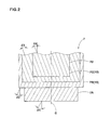
Fig. 2 is a conceptual view showing a cord arrangement of a belt layer; -
Fig. 3 is a cross sectional view showing a tread portion in an enlarged form; and -
Fig. 4 is a view illustrating a method of measuring the flexural rigidity of a cord. -
- 2.
- Tread portion
- 3.
- Sidewall portion
- 4.
- Bead portion
- 5.
- Bead core
- 6.
- Carcass
- 6A.
- Carcass ply
- 6a.
- Ply main body
- 7.
- Belt layer
- 7A-7D.
- Belt plies
- 10.
- Working belt ply
- 11.
- Reinforcing rubber layer
- An embodiment of the present invention will be explained with reference to the accompanying drawings.
Fig. 1 is a meridian cross section view showing illustratively a case where the pneumatic radial tire according to the present invention is a heavy duty tire for trucks and buses. - As shown in
Fig. 1 , a heavy dutyradial tire 1 includes acarcass 6 that extends from atread portion 2 to beadcores 5 inbead portions 4 throughsidewall portions 3, and abelt layer 7 that is disposed inside thetread portion 2 and radially outward of thecarcass 6. - The
carcass 6 is formed of asingle carcass ply 6A in which carcass cords made of a steel (steel cords) are disposed at an angle of 80 to 90° with respect to the a circumferential direction of tire and are covered with a topping rubber. This carcass ply 6A is composed of a toroidal plymain portion 6a that extends between thebead cores turnup portions 6b that are continuous with the both ends of the plymain portion 6a and are turned up around thebead cores 5 from the axially inside to the axially outside of the tire. Further, between the plymain portion 6a and theply turnup portions 6b are disposedbead apex rubbers 8 for bead reinforcement that extend radially outwardly from thebead cores 5 in a tapered manner. - The
bead apex rubber 8 is formed of a radially innerlower apex portion 8a made of a hard rubber having, for example, a rubber hardness (Durometer A hardness) of 80 to 95, and a radially outerupper apex portion 8b made of a soft rubber which is softer than the lower apex portion. Theupper apex portion 8b in this embodiment has a rubber hardness of, for example, 50 to 65, whereby shearing stress acting on theply turnup portions 6b at the time of bead deformation is reduced to prevent separation of theply turnup portions 6b. - For the purpose of reinforcing the
bead portion 4, a bead reinforcing layer 9 is disposed in thebead portion 4. The bead reinforcing layer 9 comprises a cord ply in which reinforcing cords made of a steel are arranged at an angle of, for example, 10 to 60° with respect to the tire circumferential line. The bead reinforcing layer 9 is formed into such a U-shape in cross section that aninner portion 9i extending along an axially inner surface of the plymain portion 6a and anouter portion 90 extending an axially outer surface of theturnup portion 6b are joined to both ends of abottom portion 9c passing below the bead core. - The
belt layer 7 comprises a plurality of belt plies using a belt cord made of steel (steel cord). In this embodiment is exemplified abelt layer 7 having a four layer structure in which four belt plies 7A to 7D are stacked one after another. As shown conceptually inFig. 2 , in thefirst belt ply 7A in this embodiment disposed on the radially innermost side of the belt layer, the belt cords are oriented at an angle θ1 of, for example, 60±10° with respect to the tire circumferential direction and are covered with a topping rubber. In the second to fourth belt plies 7B to 7D disposed subsequently radially outward of the first belt ply, the belt cords are oriented at small angles θ2 to θ4 of, for example, 15 to 30° with respect to the tire circumferential direction and are covered with a topping rubber. In the first and second belt plies 7A and 7B, the belt cords are inclined in one direction (diagonally right up inFig. 2 ) with respect to the tire equator C, and in the third and fifth belt plies 7C and 7D, the belt cords are inclined in the other direction (diagonally right down inFig. 2 ). - That is to say, in this embodiment, the second and third belt plies 7B and 7C constitute one and the other working belt plies 10 which overlap radially one another and whose belt cords are inclined in one and the other directions. This pair of working belt plies 10 are plies having the highest reinforcing effect among the belt plies 7A to 7D because the belt cords thereof intersect each other and bind each other. Thus, the belt rigidity is enhanced by including such a pair of the working belt plies 10, so the
tread portion 2 can be strongly reinforced with a hoop effect. Therefore, it is preferable that a width Wa of one ply (second belt ply 7B in this embodiment) of the pair of the working belt plies 10 is the largest among the belt plies 7A to 7D, and a width Wb of the other ply (third belt ply 7C in this embodiment) of the pair of the working belt plies 10 is smaller than the width Wa by about 5 to about 10 mm, thereby reducing stress concentration at ply edge while maintaining the reinforcing effect high. - As shown in
Fig. 3 in an enlarged form, theheavy duty tire 1 in this embodiment includes, between thecarcass 6 and thebelt layer 7, a reinforcingrubber layer 11 which is in the form of a sheet having a constant thickness T and has a 100% modulus M1 of not less than 2 Mpa. The thickness T of this reinforcingrubber layer 11 is from 0.3 to 3.5 mm, and the upper limit of the 100% modulus M1 is set to a value not more than a 100% modulus M2 of a topping rubber of thecarcass ply 6A and a topping rubber of the belt plies 7A to 7C. The reinforcingrubber layer 11 is in contact with both thecarcass ply 6A and thefirst belt ply 7A over the full length of therubber layer 11. A width Wy between axiallyouter edges rubber layer 11 is set within the range of 50 to 95 % of a width Wc of thefirst belt ply 7A. The reinforcingrubber layer 11 does not radially overlap acushion rubber 15 mentioned after, and the axiallyouter edges 11E of the reinforcingrubber layer 11 terminate so as to come into contact with axiallyinner edges 15E of the cushion rubbers 15. - Such a reinforcing
rubber layer 11 can maintain the rubber elasticity to some extent even in a case where thermal degradation (oxidation degradation) of a rubber is accelerated by an interaction between temperature rise to high temperature at thetread portion 2 owing to high speed running and penetration of air into the inside of a tire inflated to a high inner pressure, since the 100% modulus M1 the reinforcingrubber layer 11 is set to 2 Mpa or more. Thus, the reinforcingrubber layer 11 can exhibit an effect of suppressing generation of delamination between thecarcass 6 and thebelt layer 7. - If the 100% modulus M1 is less than 2 Mpa and the thickness T is less than 0.3 mm, the effect of suppressing the delamination cannot be exhibited. If the 100% modulus is more than the 100% modulus M1 of the topping rubber of the
carcass ply 6A and/or the topping rubber of the belt plies 7A to 7D, the topping rubber on the carcass ply side and/or the topping rubber on the belt ply side are subject to a mechanical fatigue and are broken by generation of cracks in the topping rubber layer. Further, if the thickness T is more than 3.5 mm, cornering power is greatly lowered, so the steering stability is lowered. From such points of view, it is preferable that the 100% modulus M1 is not less than 4 Mpa, and it is also preferable that the 100% modulus M1 is less than the 100% modulus M2 of the topping rubber. Further, it is preferable that the thickness T is not less than 0.5 mm, and not more than 3.0 mm. Also, if the width Wy of the reinforcingrubber layer 11 is less than 50 % of the width Wc, the delamination suppressing effect of the reinforcingrubber layer 11 cannot be sufficiently exhibited. - In this embodiment, a space between the
carcass 6 and thebelt layer 7 at both edge portions of thebelt layer 7 gradually increases toward an axially outer side of the tire, and acushion rubber 15 having an approximately triangular cross section is disposed in this space-increasing portion. Thecushion rubber 15 has the maximum thickness at a location of the outer edge of thesecond belt ply 7B, and from the maximum thickness location, it extends axially inwardly and outwardly along the outer surface of thecarcass 6 with gradually decreasing its thickness. An axiallyinner edge 15E of the cushion rubber is in contact with theouter edge 11E of the reinforcingrubber layer 11 and terminates there. Thecushion rubber 15 has a 100% modulus M3 lower than the 100% modulus M1 of the reinforcingrubber layer 11, whereby a strain between thebelt layer 7 and thecarcass 7 is absorbed to prevent loosing between the belt edge and the carcass. - In the working belt plies 10, a flexural rigidity G of the belt cord per a single cord (hereinafter sometimes referred to as "cord flexural rigidity G") is set to not more than 340 gf·cm, and a belt ply flexural rigidity defined by the product GxN of the cord flexural rigidity G and the number N of cords per inch of a working
belt ply 10 is set to not more than 3,500 gf·cm. - If the cord flexural rigidity G is more than 340 gf·cm and the belt ply flexural rigidity is more than 3,500 gf·cm, an impact-relaxing effect becomes insufficient, so it would be difficult to suppress the delamination. On the other hand, if the cord flexural rigidity G is less than 110 gf·cm and the belt ply flexural rigidity is less than 2,000 gf·cm, the reinforcing effect of the
belt layer 7 becomes insufficient to lower the cornering power, so it would be difficult to secure a necessary steering stability. From such points of view, it is preferable that the cord flexural rigidity G is not less than 110 gf·cm and is not more than 340 gf·cm. Further, it is preferable that the belt ply flexural rigidity is not less than 2,000 gf·cm and is not more than 3,500 gf·cm. - A particularly preferable embodiment of the present invention has been described, but the present invention can be modified into various embodiments and carried out without being limited to only the embodiment shown in the drawings.
- Heavy duty radial tires (tire size 315/80R22.5) having a structure shown in
Fig. 1 were manufactured based on the specifications shown in Table 1, and the durability of the tires were tested. The results are shown in Table 1. Specifications other than those described in Table 1 are common to all tires. - A tire mounted on a rim was filled with oxygen (oxygen concentration 100 %) in place of air up to an inner pressure of 900 kPa, and it was placed in a dry heat oven maintained at 70°C for 4 weeks to accelerate oxidation degradation from the inside of the tire. The tire subjected to oxidation degradation was then subjected to the following running test. The running test was made by filling the tire with normal air up to an inner pressure (900 kPa) at a maximum loading of the standard and running the tire under a loading condition (maximum load of standard × 0.85) on a drum (diameter 1.7 m) with increasing the speed stepwise by 10 km/hour every 6 hours from 80 km/hour. A speed at the time of reaching damage of the tire, a running time up to that speed and a state of breaking were compared. The temperature of the testing room was 35 ± 5°C.
- A tire mounted on a rim was run on a drum (diameter 2.0 m) under conditions of inner pressure (inner pressure at maximum loading of standard), load (maximum load of standard) and speed (4 km/h), and a cornering power at a slip angle of 1° was measured. The results are shown by an index based on a result of Example 1 regarded as 100. The larger the value, the larger the cornering power and the better the steering stability.
Table 1 Ex. 1 Ex. 2 Ex. 3 Ex. 4 Com. Ex. 1 Com. Ex. 2 Com.Ex. 3 Com. Ex. 4 Com. Ex. 5 Com. Ex. 6 Reinforcing rubber layer yes yes yes yes yes yes yes yes yes yes Thickness T (mm) 1.5 0.8 2.6 1.5 0.4 3.2 1.5 1.5 1.5 1.5 100% Modulus (Mpa) 4.0 4.0 4.0 2.3 4.0 4.0 1.8 4.0 4.0 4.0 Working belt Belt cord 1×9× 0.38 1×9× 0.38 1×9× 0.38 1×9× 0.38 1×9× 0.38 1×9× 0.38 1×9× 0.38 1×8× 0.42 1×8× 0.42 1×9× 0.38 Cord flexural rigidity G (gf·cm) 256 256 256 256 256 256 256 346 346 256 Number N of cords 12 12 12 12 12 12 12 11 10 14 Ply flexural rigidity GxN 3072 3072 3072 3072 3072 3072 3072 3806 3460 3584 Cornering power Durability 100 97 93 99 96 87 95 110 106 106 Speed (km/h) 100 100 100 100 90 100 90 90 90 90 Running time (hour) 4.5 2.2 5.0 1.5 4.7 4.8 3.6 1.0 1.3 2.1 Breaking state *1 *1 *1 *1 *2 *1 *2 *2 *2 *2 *1: Belt edge loosing
*2: Sudden delamination damage - As shown in Table 1, it is confirmed that the tires of the Examples do not cause such a breaking state as sudden delamination damage owing to thermal degradation (oxidation degradation) and remain only on a stage of belt edge loosing. It is also confirmed that lowering of the cornering powder is suppressed to a minimum, so the steering stability can be secured.
Claims (1)
- A pneumatic radial tire comprising a carcass comprising a single carcass ply which extends from a tread portion to bead cores in bead portions through sidewall portions and in which carcass cords made of a steel are arranged, and a belt layer comprising a plurality of belt plies which are disposed inside the tread portion and radially outward of the carcass and in which cords made of a steel are arranged, said pneumatic radial tire being characterized in that:said plurality of belt plies include a pair of working belt plies radially superposed on each other and comprising one working belt ply tilting in one direction with respect to a tire equator and the other working belt ply tilting in the other direction with respect to the tire equator,said one and the other working belt plies are such that a flexural rigidity G of the belt cord per a single cord falls within the range of 110 to 340 gf·cm, and a belt ply flexural rigidity defined by the product GxN of the flexural rigidity G and the number N of cords per inch of the working belt ply falls within the range of 2,000 to 3,500 gf·cm, anda reinforcing rubber layer having a 100% modulus which is not less than 2 Mpa and is not more than a 100% modulus of a topping rubber of the carcass ply and a 100% modulus of a topping rubber of the belt plies and having a thickness T of 0.3 to 3.5 mm is disposed between the carcass and the belt layer.
Applications Claiming Priority (2)
| Application Number | Priority Date | Filing Date | Title |
|---|---|---|---|
| JP2007306158A JP4330647B2 (en) | 2007-11-27 | 2007-11-27 | Pneumatic radial tire |
| PCT/JP2008/067426 WO2009069374A1 (en) | 2007-11-27 | 2008-09-26 | Pneumatic radial tire |
Publications (3)
| Publication Number | Publication Date |
|---|---|
| EP2230098A1 true EP2230098A1 (en) | 2010-09-22 |
| EP2230098A4 EP2230098A4 (en) | 2011-05-04 |
| EP2230098B1 EP2230098B1 (en) | 2012-05-02 |
Family
ID=40678279
Family Applications (1)
| Application Number | Title | Priority Date | Filing Date |
|---|---|---|---|
| EP08855108A Not-in-force EP2230098B1 (en) | 2007-11-27 | 2008-09-26 | Pneumatic radial tire |
Country Status (6)
| Country | Link |
|---|---|
| US (1) | US20100300597A1 (en) |
| EP (1) | EP2230098B1 (en) |
| JP (1) | JP4330647B2 (en) |
| CN (1) | CN101873941B (en) |
| AT (1) | ATE555924T1 (en) |
| WO (1) | WO2009069374A1 (en) |
Families Citing this family (8)
| Publication number | Priority date | Publication date | Assignee | Title |
|---|---|---|---|---|
| CN102358110B (en) * | 2011-07-04 | 2013-06-12 | 杭州中策橡胶有限公司 | Radial tire with twining type steel wire belted layer and manufacturing method thereof |
| JP5443458B2 (en) * | 2011-09-22 | 2014-03-19 | 住友ゴム工業株式会社 | All steel tire |
| JP2013221808A (en) * | 2012-04-16 | 2013-10-28 | Sumitomo Rubber Ind Ltd | Tire durability evaluation method |
| JP6139296B2 (en) * | 2013-06-25 | 2017-05-31 | 株式会社ブリヂストン | Heavy duty pneumatic tire |
| DE102013226442A1 (en) * | 2013-12-18 | 2015-06-18 | Continental Reifen Deutschland Gmbh | Vehicle tires |
| DE102013226443A1 (en) * | 2013-12-18 | 2015-06-18 | Continental Reifen Deutschland Gmbh | Vehicle tires |
| CN106938593B (en) * | 2017-04-24 | 2019-04-02 | 江苏通用科技股份有限公司 | High centrifugal force resistant tire crown structure |
| JP6737349B2 (en) * | 2019-01-10 | 2020-08-05 | 横浜ゴム株式会社 | Pneumatic radial tires |
Family Cites Families (8)
| Publication number | Priority date | Publication date | Assignee | Title |
|---|---|---|---|---|
| JPS59204634A (en) * | 1983-05-06 | 1984-11-20 | Ube Ind Ltd | Tire cord coating rubber composition |
| JPS60131303A (en) * | 1983-12-19 | 1985-07-13 | Sumitomo Rubber Ind Ltd | pneumatic tires |
| JPS60143106A (en) * | 1983-12-29 | 1985-07-29 | Bridgestone Corp | Pneumatic radial tire for heavy load |
| US4690191A (en) * | 1984-12-21 | 1987-09-01 | Bridgestone Corporation | Radial tire with reinforcing steel cord |
| JPH05294108A (en) * | 1992-04-20 | 1993-11-09 | Bridgestone Corp | Pneumatic radial tire for construction vehicle |
| JP3389488B2 (en) * | 1998-02-10 | 2003-03-24 | 住友ゴム工業株式会社 | Radial tires for heavy loads |
| JP3398065B2 (en) * | 1998-08-28 | 2003-04-21 | 住友ゴム工業株式会社 | Radial tires for heavy loads |
| JP2000225806A (en) * | 1999-02-05 | 2000-08-15 | Bridgestone Corp | Pneumatic radial tire for passenger car |
-
2007
- 2007-11-27 JP JP2007306158A patent/JP4330647B2/en not_active Expired - Fee Related
-
2008
- 2008-09-26 US US12/744,821 patent/US20100300597A1/en not_active Abandoned
- 2008-09-26 WO PCT/JP2008/067426 patent/WO2009069374A1/en not_active Ceased
- 2008-09-26 CN CN2008801187003A patent/CN101873941B/en not_active Expired - Fee Related
- 2008-09-26 EP EP08855108A patent/EP2230098B1/en not_active Not-in-force
- 2008-09-26 AT AT08855108T patent/ATE555924T1/en active
Non-Patent Citations (2)
| Title |
|---|
| No further relevant documents disclosed * |
| See also references of WO2009069374A1 * |
Also Published As
| Publication number | Publication date |
|---|---|
| JP2009126459A (en) | 2009-06-11 |
| WO2009069374A1 (en) | 2009-06-04 |
| ATE555924T1 (en) | 2012-05-15 |
| CN101873941A (en) | 2010-10-27 |
| US20100300597A1 (en) | 2010-12-02 |
| JP4330647B2 (en) | 2009-09-16 |
| CN101873941B (en) | 2013-11-27 |
| EP2230098A4 (en) | 2011-05-04 |
| EP2230098B1 (en) | 2012-05-02 |
Similar Documents
| Publication | Publication Date | Title |
|---|---|---|
| EP2230098B1 (en) | Pneumatic radial tire | |
| EP2292450B1 (en) | Heavy duty pneumatic tire | |
| EP1393931A1 (en) | Pneumatic tire | |
| EP2355986B1 (en) | Pneumatic vehicle tire | |
| EP1872972A2 (en) | Heavy duty pneumatic tire | |
| EP2098385A1 (en) | Pneumatic tire | |
| US20120060995A1 (en) | Heavy duty tire | |
| EP2676812A1 (en) | Pneumatic tire | |
| EP2322360B1 (en) | Heavy duty tire | |
| EP2505388A1 (en) | Air-filled radial tire for heavy loads | |
| EP2123483A1 (en) | Pneumatic tire | |
| CN100406278C (en) | pneumatic tire | |
| CN100532137C (en) | truck tire | |
| US9139050B2 (en) | Pneumatic tire having first and second turnup pads | |
| EP1859964A1 (en) | Pneumatic tire | |
| ZA201007815B (en) | Heavy duty tire | |
| EP3597453A1 (en) | Pneumatic tyre | |
| EP2050586A1 (en) | Pneumatic tire | |
| EP3138700B1 (en) | Pneumatic tire | |
| JP2009292425A (en) | Large-sized pneumatic radial tire | |
| JP2003104016A (en) | Pneumatic tire | |
| EP1714801B1 (en) | Pneumatic tire for aircraft | |
| CN105899373B (en) | Pneumatic tire | |
| EP1800909A2 (en) | Pneumatic tire | |
| CN112739557A (en) | Tire with reduced weight bead area |
Legal Events
| Date | Code | Title | Description |
|---|---|---|---|
| PUAI | Public reference made under article 153(3) epc to a published international application that has entered the european phase |
Free format text: ORIGINAL CODE: 0009012 |
|
| 17P | Request for examination filed |
Effective date: 20100622 |
|
| AK | Designated contracting states |
Kind code of ref document: A1 Designated state(s): AT BE BG CH CY CZ DE DK EE ES FI FR GB GR HR HU IE IS IT LI LT LU LV MC MT NL NO PL PT RO SE SI SK TR |
|
| AX | Request for extension of the european patent |
Extension state: AL BA MK RS |
|
| DAX | Request for extension of the european patent (deleted) | ||
| A4 | Supplementary search report drawn up and despatched |
Effective date: 20110405 |
|
| RIC1 | Information provided on ipc code assigned before grant |
Ipc: B60C 9/20 20060101ALI20110330BHEP Ipc: B60C 9/18 20060101AFI20110330BHEP |
|
| GRAP | Despatch of communication of intention to grant a patent |
Free format text: ORIGINAL CODE: EPIDOSNIGR1 |
|
| RIC1 | Information provided on ipc code assigned before grant |
Ipc: B60C 9/20 20060101ALI20111128BHEP Ipc: B60C 9/18 20060101AFI20111128BHEP |
|
| GRAS | Grant fee paid |
Free format text: ORIGINAL CODE: EPIDOSNIGR3 |
|
| GRAA | (expected) grant |
Free format text: ORIGINAL CODE: 0009210 |
|
| AK | Designated contracting states |
Kind code of ref document: B1 Designated state(s): AT BE BG CH CY CZ DE DK EE ES FI FR GB GR HR HU IE IS IT LI LT LU LV MC MT NL NO PL PT RO SE SI SK TR |
|
| REG | Reference to a national code |
Ref country code: GB Ref legal event code: FG4D |
|
| REG | Reference to a national code |
Ref country code: AT Ref legal event code: REF Ref document number: 555924 Country of ref document: AT Kind code of ref document: T Effective date: 20120515 Ref country code: CH Ref legal event code: EP |
|
| REG | Reference to a national code |
Ref country code: IE Ref legal event code: FG4D |
|
| REG | Reference to a national code |
Ref country code: DE Ref legal event code: R096 Ref document number: 602008015449 Country of ref document: DE Effective date: 20120705 |
|
| REG | Reference to a national code |
Ref country code: NL Ref legal event code: VDEP Effective date: 20120502 |
|
| REG | Reference to a national code |
Ref country code: LT Ref legal event code: MG4D Effective date: 20120502 |
|
| PG25 | Lapsed in a contracting state [announced via postgrant information from national office to epo] |
Ref country code: IS Free format text: LAPSE BECAUSE OF FAILURE TO SUBMIT A TRANSLATION OF THE DESCRIPTION OR TO PAY THE FEE WITHIN THE PRESCRIBED TIME-LIMIT Effective date: 20120902 Ref country code: PL Free format text: LAPSE BECAUSE OF FAILURE TO SUBMIT A TRANSLATION OF THE DESCRIPTION OR TO PAY THE FEE WITHIN THE PRESCRIBED TIME-LIMIT Effective date: 20120502 Ref country code: FI Free format text: LAPSE BECAUSE OF FAILURE TO SUBMIT A TRANSLATION OF THE DESCRIPTION OR TO PAY THE FEE WITHIN THE PRESCRIBED TIME-LIMIT Effective date: 20120502 Ref country code: SE Free format text: LAPSE BECAUSE OF FAILURE TO SUBMIT A TRANSLATION OF THE DESCRIPTION OR TO PAY THE FEE WITHIN THE PRESCRIBED TIME-LIMIT Effective date: 20120502 Ref country code: LT Free format text: LAPSE BECAUSE OF FAILURE TO SUBMIT A TRANSLATION OF THE DESCRIPTION OR TO PAY THE FEE WITHIN THE PRESCRIBED TIME-LIMIT Effective date: 20120502 Ref country code: CY Free format text: LAPSE BECAUSE OF FAILURE TO SUBMIT A TRANSLATION OF THE DESCRIPTION OR TO PAY THE FEE WITHIN THE PRESCRIBED TIME-LIMIT Effective date: 20120502 Ref country code: NO Free format text: LAPSE BECAUSE OF FAILURE TO SUBMIT A TRANSLATION OF THE DESCRIPTION OR TO PAY THE FEE WITHIN THE PRESCRIBED TIME-LIMIT Effective date: 20120802 |
|
| REG | Reference to a national code |
Ref country code: AT Ref legal event code: MK05 Ref document number: 555924 Country of ref document: AT Kind code of ref document: T Effective date: 20120502 |
|
| PG25 | Lapsed in a contracting state [announced via postgrant information from national office to epo] |
Ref country code: GR Free format text: LAPSE BECAUSE OF FAILURE TO SUBMIT A TRANSLATION OF THE DESCRIPTION OR TO PAY THE FEE WITHIN THE PRESCRIBED TIME-LIMIT Effective date: 20120803 Ref country code: LV Free format text: LAPSE BECAUSE OF FAILURE TO SUBMIT A TRANSLATION OF THE DESCRIPTION OR TO PAY THE FEE WITHIN THE PRESCRIBED TIME-LIMIT Effective date: 20120502 Ref country code: SI Free format text: LAPSE BECAUSE OF FAILURE TO SUBMIT A TRANSLATION OF THE DESCRIPTION OR TO PAY THE FEE WITHIN THE PRESCRIBED TIME-LIMIT Effective date: 20120502 Ref country code: HR Free format text: LAPSE BECAUSE OF FAILURE TO SUBMIT A TRANSLATION OF THE DESCRIPTION OR TO PAY THE FEE WITHIN THE PRESCRIBED TIME-LIMIT Effective date: 20120502 Ref country code: PT Free format text: LAPSE BECAUSE OF FAILURE TO SUBMIT A TRANSLATION OF THE DESCRIPTION OR TO PAY THE FEE WITHIN THE PRESCRIBED TIME-LIMIT Effective date: 20120903 |
|
| PG25 | Lapsed in a contracting state [announced via postgrant information from national office to epo] |
Ref country code: BE Free format text: LAPSE BECAUSE OF FAILURE TO SUBMIT A TRANSLATION OF THE DESCRIPTION OR TO PAY THE FEE WITHIN THE PRESCRIBED TIME-LIMIT Effective date: 20120502 |
|
| PG25 | Lapsed in a contracting state [announced via postgrant information from national office to epo] |
Ref country code: RO Free format text: LAPSE BECAUSE OF FAILURE TO SUBMIT A TRANSLATION OF THE DESCRIPTION OR TO PAY THE FEE WITHIN THE PRESCRIBED TIME-LIMIT Effective date: 20120502 Ref country code: NL Free format text: LAPSE BECAUSE OF FAILURE TO SUBMIT A TRANSLATION OF THE DESCRIPTION OR TO PAY THE FEE WITHIN THE PRESCRIBED TIME-LIMIT Effective date: 20120502 Ref country code: EE Free format text: LAPSE BECAUSE OF FAILURE TO SUBMIT A TRANSLATION OF THE DESCRIPTION OR TO PAY THE FEE WITHIN THE PRESCRIBED TIME-LIMIT Effective date: 20120502 Ref country code: DK Free format text: LAPSE BECAUSE OF FAILURE TO SUBMIT A TRANSLATION OF THE DESCRIPTION OR TO PAY THE FEE WITHIN THE PRESCRIBED TIME-LIMIT Effective date: 20120502 Ref country code: AT Free format text: LAPSE BECAUSE OF FAILURE TO SUBMIT A TRANSLATION OF THE DESCRIPTION OR TO PAY THE FEE WITHIN THE PRESCRIBED TIME-LIMIT Effective date: 20120502 Ref country code: SK Free format text: LAPSE BECAUSE OF FAILURE TO SUBMIT A TRANSLATION OF THE DESCRIPTION OR TO PAY THE FEE WITHIN THE PRESCRIBED TIME-LIMIT Effective date: 20120502 Ref country code: CZ Free format text: LAPSE BECAUSE OF FAILURE TO SUBMIT A TRANSLATION OF THE DESCRIPTION OR TO PAY THE FEE WITHIN THE PRESCRIBED TIME-LIMIT Effective date: 20120502 |
|
| PG25 | Lapsed in a contracting state [announced via postgrant information from national office to epo] |
Ref country code: IT Free format text: LAPSE BECAUSE OF FAILURE TO SUBMIT A TRANSLATION OF THE DESCRIPTION OR TO PAY THE FEE WITHIN THE PRESCRIBED TIME-LIMIT Effective date: 20120502 |
|
| PLBE | No opposition filed within time limit |
Free format text: ORIGINAL CODE: 0009261 |
|
| STAA | Information on the status of an ep patent application or granted ep patent |
Free format text: STATUS: NO OPPOSITION FILED WITHIN TIME LIMIT |
|
| 26N | No opposition filed |
Effective date: 20130205 |
|
| PG25 | Lapsed in a contracting state [announced via postgrant information from national office to epo] |
Ref country code: ES Free format text: LAPSE BECAUSE OF FAILURE TO SUBMIT A TRANSLATION OF THE DESCRIPTION OR TO PAY THE FEE WITHIN THE PRESCRIBED TIME-LIMIT Effective date: 20120813 Ref country code: MC Free format text: LAPSE BECAUSE OF NON-PAYMENT OF DUE FEES Effective date: 20120930 |
|
| REG | Reference to a national code |
Ref country code: CH Ref legal event code: PL |
|
| GBPC | Gb: european patent ceased through non-payment of renewal fee |
Effective date: 20120926 |
|
| REG | Reference to a national code |
Ref country code: DE Ref legal event code: R097 Ref document number: 602008015449 Country of ref document: DE Effective date: 20130205 |
|
| REG | Reference to a national code |
Ref country code: IE Ref legal event code: MM4A |
|
| REG | Reference to a national code |
Ref country code: FR Ref legal event code: ST Effective date: 20130531 |
|
| PG25 | Lapsed in a contracting state [announced via postgrant information from national office to epo] |
Ref country code: GB Free format text: LAPSE BECAUSE OF NON-PAYMENT OF DUE FEES Effective date: 20120926 Ref country code: LI Free format text: LAPSE BECAUSE OF NON-PAYMENT OF DUE FEES Effective date: 20120930 Ref country code: IE Free format text: LAPSE BECAUSE OF NON-PAYMENT OF DUE FEES Effective date: 20120926 Ref country code: CH Free format text: LAPSE BECAUSE OF NON-PAYMENT OF DUE FEES Effective date: 20120930 Ref country code: BG Free format text: LAPSE BECAUSE OF FAILURE TO SUBMIT A TRANSLATION OF THE DESCRIPTION OR TO PAY THE FEE WITHIN THE PRESCRIBED TIME-LIMIT Effective date: 20120802 |
|
| PG25 | Lapsed in a contracting state [announced via postgrant information from national office to epo] |
Ref country code: FR Free format text: LAPSE BECAUSE OF NON-PAYMENT OF DUE FEES Effective date: 20121001 |
|
| PG25 | Lapsed in a contracting state [announced via postgrant information from national office to epo] |
Ref country code: MT Free format text: LAPSE BECAUSE OF FAILURE TO SUBMIT A TRANSLATION OF THE DESCRIPTION OR TO PAY THE FEE WITHIN THE PRESCRIBED TIME-LIMIT Effective date: 20120502 |
|
| PG25 | Lapsed in a contracting state [announced via postgrant information from national office to epo] |
Ref country code: TR Free format text: LAPSE BECAUSE OF FAILURE TO SUBMIT A TRANSLATION OF THE DESCRIPTION OR TO PAY THE FEE WITHIN THE PRESCRIBED TIME-LIMIT Effective date: 20120502 |
|
| PG25 | Lapsed in a contracting state [announced via postgrant information from national office to epo] |
Ref country code: LU Free format text: LAPSE BECAUSE OF NON-PAYMENT OF DUE FEES Effective date: 20120926 |
|
| PG25 | Lapsed in a contracting state [announced via postgrant information from national office to epo] |
Ref country code: HU Free format text: LAPSE BECAUSE OF FAILURE TO SUBMIT A TRANSLATION OF THE DESCRIPTION OR TO PAY THE FEE WITHIN THE PRESCRIBED TIME-LIMIT Effective date: 20080926 |
|
| PGFP | Annual fee paid to national office [announced via postgrant information from national office to epo] |
Ref country code: DE Payment date: 20220621 Year of fee payment: 15 |
|
| REG | Reference to a national code |
Ref country code: DE Ref legal event code: R119 Ref document number: 602008015449 Country of ref document: DE |
|
| PG25 | Lapsed in a contracting state [announced via postgrant information from national office to epo] |
Ref country code: DE Free format text: LAPSE BECAUSE OF NON-PAYMENT OF DUE FEES Effective date: 20240403 |