EP2229928A1 - System and devices for aseptic handling of materials - Google Patents
System and devices for aseptic handling of materials Download PDFInfo
- Publication number
- EP2229928A1 EP2229928A1 EP09155764A EP09155764A EP2229928A1 EP 2229928 A1 EP2229928 A1 EP 2229928A1 EP 09155764 A EP09155764 A EP 09155764A EP 09155764 A EP09155764 A EP 09155764A EP 2229928 A1 EP2229928 A1 EP 2229928A1
- Authority
- EP
- European Patent Office
- Prior art keywords
- airlock
- chamber
- rotatable member
- isolator
- materials
- Prior art date
- Legal status (The legal status is an assumption and is not a legal conclusion. Google has not performed a legal analysis and makes no representation as to the accuracy of the status listed.)
- Withdrawn
Links
- 239000000463 material Substances 0.000 title claims abstract description 21
- 239000007788 liquid Substances 0.000 claims description 14
- 239000012530 fluid Substances 0.000 claims description 10
- 238000005507 spraying Methods 0.000 claims description 10
- 230000001954 sterilising effect Effects 0.000 claims description 10
- 239000002245 particle Substances 0.000 description 12
- LFQSCWFLJHTTHZ-UHFFFAOYSA-N Ethanol Chemical compound CCO LFQSCWFLJHTTHZ-UHFFFAOYSA-N 0.000 description 4
- 101000793686 Homo sapiens Azurocidin Proteins 0.000 description 4
- 210000002105 tongue Anatomy 0.000 description 4
- 238000011109 contamination Methods 0.000 description 3
- 229910052751 metal Inorganic materials 0.000 description 3
- 239000002184 metal Substances 0.000 description 3
- 150000001875 compounds Chemical class 0.000 description 2
- 238000012864 cross contamination Methods 0.000 description 2
- 239000003085 diluting agent Substances 0.000 description 2
- 239000003814 drug Substances 0.000 description 2
- 229940079593 drug Drugs 0.000 description 2
- 230000000694 effects Effects 0.000 description 2
- 238000005516 engineering process Methods 0.000 description 2
- 238000011010 flushing procedure Methods 0.000 description 2
- 238000004519 manufacturing process Methods 0.000 description 2
- 238000000034 method Methods 0.000 description 2
- 238000004659 sterilization and disinfection Methods 0.000 description 2
- 241000894006 Bacteria Species 0.000 description 1
- FAPWRFPIFSIZLT-UHFFFAOYSA-M Sodium chloride Chemical compound [Na+].[Cl-] FAPWRFPIFSIZLT-UHFFFAOYSA-M 0.000 description 1
- 238000004880 explosion Methods 0.000 description 1
- 238000002347 injection Methods 0.000 description 1
- 239000007924 injection Substances 0.000 description 1
- 229940126601 medicinal product Drugs 0.000 description 1
- 238000011169 microbiological contamination Methods 0.000 description 1
- 238000012544 monitoring process Methods 0.000 description 1
- 239000005022 packaging material Substances 0.000 description 1
- 230000000717 retained effect Effects 0.000 description 1
- 239000007921 spray Substances 0.000 description 1
- 239000000126 substance Substances 0.000 description 1
- 230000000153 supplemental effect Effects 0.000 description 1
Images


Classifications
-
- A—HUMAN NECESSITIES
- A61—MEDICAL OR VETERINARY SCIENCE; HYGIENE
- A61J—CONTAINERS SPECIALLY ADAPTED FOR MEDICAL OR PHARMACEUTICAL PURPOSES; DEVICES OR METHODS SPECIALLY ADAPTED FOR BRINGING PHARMACEUTICAL PRODUCTS INTO PARTICULAR PHYSICAL OR ADMINISTERING FORMS; DEVICES FOR ADMINISTERING FOOD OR MEDICINES ORALLY; BABY COMFORTERS; DEVICES FOR RECEIVING SPITTLE
- A61J1/00—Containers specially adapted for medical or pharmaceutical purposes
- A61J1/14—Details; Accessories therefor
- A61J1/20—Arrangements for transferring or mixing fluids, e.g. from vial to syringe
-
- A—HUMAN NECESSITIES
- A61—MEDICAL OR VETERINARY SCIENCE; HYGIENE
- A61J—CONTAINERS SPECIALLY ADAPTED FOR MEDICAL OR PHARMACEUTICAL PURPOSES; DEVICES OR METHODS SPECIALLY ADAPTED FOR BRINGING PHARMACEUTICAL PRODUCTS INTO PARTICULAR PHYSICAL OR ADMINISTERING FORMS; DEVICES FOR ADMINISTERING FOOD OR MEDICINES ORALLY; BABY COMFORTERS; DEVICES FOR RECEIVING SPITTLE
- A61J3/00—Devices or methods specially adapted for bringing pharmaceutical products into particular physical or administering forms
- A61J3/002—Compounding apparatus specially for enteral or parenteral nutritive solutions
-
- B—PERFORMING OPERATIONS; TRANSPORTING
- B65—CONVEYING; PACKING; STORING; HANDLING THIN OR FILAMENTARY MATERIAL
- B65B—MACHINES, APPARATUS OR DEVICES FOR, OR METHODS OF, PACKAGING ARTICLES OR MATERIALS; UNPACKING
- B65B3/00—Packaging plastic material, semiliquids, liquids or mixed solids and liquids, in individual containers or receptacles, e.g. bags, sacks, boxes, cartons, cans, or jars
- B65B3/003—Filling medical containers such as ampoules, vials, syringes or the like
Definitions
- This invention relates to apparatus and devices for aseptic handling and manipulation of devices used in the pharmaceutical industry and in hospitals when handling sterile substances and devices.
- WO 2008/009288 relates to a sterilisable connector device for establishing fluid connection between a container holding a sterile diluent liquid such as isotonic sodium chloride solution, and a vial holding a pharmaceutical compound, so that the diluent liquid and the pharmaceutical compound are mixed to provide a sterile injection fluid.
- a sterile diluent liquid such as isotonic sodium chloride solution
- isolator technology is prescribed to minimise human interventions in processing areas resulting in a significant decrease in the risk of microbiological contamination of aseptically manufactured products from the environment.
- Access for equipment and materials to the isolator takes place through an airlock chamber.
- Laminar air flow is prescribed, and the content of particles in the air must be kept below specified limits.
- Isolators for aseptic handling and manipulation of materials are typically specified to Grade A, i.e. having a laminar air flow at a velocity of 0.36 - 0.54 m/s as a guidance value and no more than 3,500 particles of size 0.5 ⁇ m per m 3 (100 particles per cu. ft.).
- the air outside the isolator has no more than 35,000 such particles per m 3 , i.e. no more than 10 times as many particles as the upper limit for the isolator chamber.
- the connector device of WO 2008/009288 has an engagement member with a collar having a rim for receiving the neck of a vial by a lateral movement.
- the engagement member In order to prevent the vial from being removed and to prevent contamination of portions to be kept sterile, the engagement member must be rotated 180 degrees whereby a member with an external thread is advanced from the engagement member and brought in contact with the rubber seal, whereby lateral movement is prevented and the vial is locked in its position in the collar of the connector device.
- Connecting the connector device of WO 2008/009288 with a vial and a diluent-liquid container can be done manually or automatically using specialised equipment such as robot technology. Many elemental processes must be performed including the above mentioned rotation of the engagement member of the connector device.
- the vial and the diluent-liquid container each has a neck with a rubber seal to be pierced when their contents are to be mixed.
- their rubber seals must be sterilised.
- sterilising is done using e.g. a swab containing a sterilising liquid such as ethanol and rubbing the area to be sterilised with the swab.
- the invention provides a system and devices that solve the above problems.
- the isolator and airlock system of the invention can be placed in a room where the air may contain 350,000 0.5 ⁇ m particles (10,000 particles per cu. ft.), i.e. 100 times more than the upper limit for the isolator chamber. This reduces the complexity of the entire facility where an isolator system of the invention can be installed.
- Figures 1 and 2 show the connector device 1 disclosed in WO 2008/009288 .
- the connector device 1 has an engagement member 14 with a collar 17 and a rim 18 on the collar.
- a vial 23 has a neck 34 that by a lateral movement has been received in the collar 17 and retained by the rim 18.
- the connector device 1 has a tube member 4 with an external thread, and the engagement member 14 has a bore with an internal thread in engagement with the external thread of the tube member 4.
- the tube member 4 there is a piercing member for piercing the seal 36 of the vial.
- a piercable cap 40 covers the piercing end of the piercing member.
- the engagement member 14 is rotated 180 degrees whereby the tube member 4 and the piercable cap 40 are advanced so that the piercable cap 40 protrudes through the central opening 27 in the metal cap 37 covering the seal 36 and is pressed slightly against the top part 41 of the seal. Reversal of this rotation is prevented by detent means on the threaded parts, and removal of the vial is hereby prevented.
- This structure and function is disclosed in detail in WO 2008/009288 .
- FIG. 3 shows how the rotation of the engagement member 14 is carried out in a device according to the invention.
- An elongate member 301 is rotatable about an axis of rotation 302.
- the elongate member 301 has two identical ends each of which has a pair of tongues 303 with a pair of opposed walls that define a radially extending and open-ended space between the tongues.
- the engagement member 14 of a connector device can be received in the space between the tongues in a movement radially relative to the axis of rotation 302.
- the connector device and the attached vial are engaged e.g. by a robot gripping mechanism which places the engagement member 14 as shown in the space between the pair of tongues 303.
- the vial 23 and the remaining parts of the connector device are held and being prevented from rotation while the entire assembly of the connector device and the vial is moved as indicated by a dashed-line arrow.
- the engagement member 14 is rotated 180 degrees relative to the vial and the remaining parts of the connector device.
- a small “x" on the cap 37 of the vial indicates that the vial is not rotated, and a small “o” on the engagement member 14 indicates that it is rotated together with the rotatable elongate member 301.
- the rotation is 180 degrees and by rotation of the elongate member 301 through this angle the other end is positioned to receive the engagement member of another connecting device. Rotation through other angles than 180 degrees can also be effected if so desired. If the rotation is a fraction 1/n of 360 degrees where n is an integer number, the rotatable member can advantageously have n spaces for engaging and rotating the engagement member 14 equidistantly distributed along a circle with its centre on the axis of rotation. Thereby the rotatable member will always be left in a position ready to receive an engagement member when an engagement member leaves the space after having been rotated.
- the device preferably has a self-aligning mechanism which aligns an empty space for receiving an engagement member to be rotated.
- Figures 5 and 6 show a known vial 23 with a seal 36.
- a metal cap 37 with a central opening 38 covers the seal 36.
- the metal cap 37 is bent around the neck 35 of the vial 23.
- the top part 41 of the seal is exposed and must be sterilised before being brought into connection with a connector device 1.
- Figure 6 illustrates how a spraying device 60 sprays a sterilising fluid such as ethanol onto the top part 41.
- a sterilising fluid such as ethanol
- the fluid will have a flushing effect whereby possible particles will be removed, and possible remaining bacteria will be killed.
- both the spraying pressure and the opening angle of the spraying cone can be varied to obtain both a flushing effect and a desired distribution of the sterilising liquid.
- the spraying device 60 does not come into contact with any part of the vial but the sterilising liquid is sprayed onto the top part of the vial whereby contamination and cross contamination is prevented.
- the vial 23 is oriented upside down and the spraying device 60 is arranged below the vial, but any orientation can be used.
- spraying devices that can be used is model EFD-781 from Engineered Fluid Dispensing.
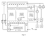
- figure 4 is shown schematically the arrangement of a system 400 according to the invention for aseptic handling of materials, and in particular for aseptically connecting a connecting device 1 as disclosed in WO 2008/009288 to a vial and a diluent-liquid container.
- the system 400 has an isolator chamber with arrangements for aseptic handling of the materials.
- the handling is preferably done by programmable robots.
- Two airlock chambers each having two sliding doors allow materials to be transported into and out of the isolator chamber.
- Such materials include primarily connector devices, vials 23 and diluent-liquid containers to be connected, but also trays and packaging materials.
- the system includes High Efficiency Particulate Arresting, HEPA, filters P1 and p2 and motor-driven blowers for establishing a laminar air flow in the airlock chambers and in the isolator chamber.
- HEPA High Efficiency Particulate Arresting
- filters P1 and p2 and motor-driven blowers for establishing a laminar air flow in the airlock chambers and in the isolator chamber.
- a pressure which is higher than the pressure outside the airlock chambers is established, e.g. 15 Pa
- a pressure which is higher than the pressure in the airlock chambers is established, e.g. 30 Pa. This ensures that each of the airlock chambers (with all doors closed) and in the isolator chamber meet the specifications of maximum 100 particles 0.5 ⁇ m per cu. ft. corresponding to 3,500 particles 0.5 ⁇ m per m 3 .
- HEPA filters P3 and P4 filter the return air from the airlock chambers and the isolator chamber to ensure that e.g. drugs from vials that are broken inside the airlock chambers or the isolator chamber are filtered and not re-circulated.
- Supplemental air for compensating the loss of air through the doors etc. is fed through HEPA filters P5 and P6 where in particular drugs from vials that are broken outside the airlock chambers or the isolator chamber are filtered and are not fed into the airlock chambers or the isolator chamber.
- a controller In the lower compartment of the system a controller is situated. The controller controls the operation of all components of the system. Since this compartment is not a "clean" area the pressure is kept below the pressure outside the system, e.g. -15 Pa. Particle filter P9 filters the air that enters the lower compartment of the system.
- the controller controls the robots handling and manipulation of the materials (connector devices, vials and diluent-liquid containers), the operation of the sliding doors and blower motors.
- the controller In order to maintain aseptic conditions in the isolator chamber and the airlock chambers the controller is adapted to open an airlock door to the outside only when the corresponding airlock door to the isolator chamber is closed. This allows transport of the materials between the outside and the airlock chamber. Further, the controller will open an airlock door to the isolator chamber only when the corresponding airlock door to the outside is closed and aseptic conditions have been established in the airlock chamber. This allows transport of the materials between the airlock chamber and the isolator chamber.
- the system may have means for monitoring when aseptic conditions actually have been established in individual ones of the airlock chambers and the isolator chamber and open a door to the isolator chamber only when it has been determined based on actual observations that aseptic conditions have been established, or the system may be suitably programmed only to open a door to the isolator chamber after a predefined delay time after the corresponding airlock chamber door to the outside was closed.
- the airlock doors are sliding doors which require less space than traditional hinged doors.
Landscapes
- Health & Medical Sciences (AREA)
- Pharmacology & Pharmacy (AREA)
- Life Sciences & Earth Sciences (AREA)
- Animal Behavior & Ethology (AREA)
- General Health & Medical Sciences (AREA)
- Public Health (AREA)
- Veterinary Medicine (AREA)
- Nutrition Science (AREA)
- Chemical & Material Sciences (AREA)
- Medicinal Chemistry (AREA)
- Apparatus For Disinfection Or Sterilisation (AREA)
- Manipulator (AREA)
Abstract
Description
- This invention relates to apparatus and devices for aseptic handling and manipulation of devices used in the pharmaceutical industry and in hospitals when handling sterile substances and devices.
-
WO 2008/009288 relates to a sterilisable connector device for establishing fluid connection between a container holding a sterile diluent liquid such as isotonic sodium chloride solution, and a vial holding a pharmaceutical compound, so that the diluent liquid and the pharmaceutical compound are mixed to provide a sterile injection fluid. - The handling of such connector device for establishing interconnection liquid container and vial must take place under aseptic conditions. Reference is made to e.g. the publication Manufacture of Sterile Medicinal Products, an EC Guide to manufacturing Practice by the European Commission, 30 May 2003.
- The use of isolator technology is prescribed to minimise human interventions in processing areas resulting in a significant decrease in the risk of microbiological contamination of aseptically manufactured products from the environment. Access for equipment and materials to the isolator takes place through an airlock chamber. Laminar air flow is prescribed, and the content of particles in the air must be kept below specified limits. Isolators for aseptic handling and manipulation of materials are typically specified to Grade A, i.e. having a laminar air flow at a velocity of 0.36 - 0.54 m/s as a guidance value and no more than 3,500 particles of size 0.5 µm per m3 (100 particles per cu. ft.). This requires that the air outside the isolator has no more than 35,000 such particles per m3, i.e. no more than 10 times as many particles as the upper limit for the isolator chamber. In order to achieve this there is usually at least one further, outer airlock system.
- The connector device of
WO 2008/009288 has an engagement member with a collar having a rim for receiving the neck of a vial by a lateral movement. In order to prevent the vial from being removed and to prevent contamination of portions to be kept sterile, the engagement member must be rotated 180 degrees whereby a member with an external thread is advanced from the engagement member and brought in contact with the rubber seal, whereby lateral movement is prevented and the vial is locked in its position in the collar of the connector device. For further details reference is made toWO 2008/009288 . - Connecting the connector device of
WO 2008/009288 with a vial and a diluent-liquid container can be done manually or automatically using specialised equipment such as robot technology. Many elemental processes must be performed including the above mentioned rotation of the engagement member of the connector device. - The vial and the diluent-liquid container each has a neck with a rubber seal to be pierced when their contents are to be mixed. Before connecting the vial and the diluent-liquid container to the connector their rubber seals must be sterilised. Today, such sterilising is done using e.g. a swab containing a sterilising liquid such as ethanol and rubbing the area to be sterilised with the swab. There is a potential risk of contamination and cross contamination transferred by the swab, and therefore there is a need for a method reducing this risk.
- The invention provides a system and devices that solve the above problems. In particular, the isolator and airlock system of the invention can be placed in a room where the air may contain 350,000 0.5 µm particles (10,000 particles per cu. ft.), i.e. 100 times more than the upper limit for the isolator chamber. This reduces the complexity of the entire facility where an isolator system of the invention can be installed.
-
-
Figure 1 shows a vial connected to a connector device; -
Figure 2 shows the vial and the connector device infigure 1 in a configuration where the vial is locked to the connector device; -
Figure 3 shows a system for manipulating the vial and the connector device infigure 1 ; -
Figure 4 shows schematically a system according to the invention for aseptic handling of materials; -
Figure 5 shows a vial; and -
Figure 6 shows schematically the sterilisation of the seal of the vial infigure 5 before being connected to a connector device. -
Figures 1 and 2 show theconnector device 1 disclosed inWO 2008/009288 . Theconnector device 1 has anengagement member 14 with acollar 17 and arim 18 on the collar. Avial 23 has aneck 34 that by a lateral movement has been received in thecollar 17 and retained by therim 18. Theconnector device 1 has a tube member 4 with an external thread, and theengagement member 14 has a bore with an internal thread in engagement with the external thread of the tube member 4. The tube member 4 there is a piercing member for piercing theseal 36 of the vial. Apiercable cap 40 covers the piercing end of the piercing member. - In
figure 1 the end of thepiercable cap 40 is flush with the bottom of the cavity defined by thecollar 17 which allows the top of the vial to be inserted laterally into the cavity and gripped by therim 18 of thecollar 17. - In order to prevent the
vial 23 from being removed from thecollar 17 of theengagement member 14, theengagement member 14 is rotated 180 degrees whereby the tube member 4 and thepiercable cap 40 are advanced so that thepiercable cap 40 protrudes through the central opening 27 in themetal cap 37 covering theseal 36 and is pressed slightly against thetop part 41 of the seal. Reversal of this rotation is prevented by detent means on the threaded parts, and removal of the vial is hereby prevented. This structure and function is disclosed in detail inWO 2008/009288 . -
Figure 3 shows how the rotation of theengagement member 14 is carried out in a device according to the invention. Anelongate member 301 is rotatable about an axis ofrotation 302. Theelongate member 301 has two identical ends each of which has a pair oftongues 303 with a pair of opposed walls that define a radially extending and open-ended space between the tongues. Theengagement member 14 of a connector device can be received in the space between the tongues in a movement radially relative to the axis ofrotation 302. In the system of the invention to be described below the connector device and the attached vial are engaged e.g. by a robot gripping mechanism which places theengagement member 14 as shown in the space between the pair oftongues 303. Thevial 23 and the remaining parts of the connector device are held and being prevented from rotation while the entire assembly of the connector device and the vial is moved as indicated by a dashed-line arrow. Hereby theengagement member 14 is rotated 180 degrees relative to the vial and the remaining parts of the connector device. A small "x" on thecap 37 of the vial indicates that the vial is not rotated, and a small "o" on theengagement member 14 indicates that it is rotated together with the rotatableelongate member 301. - In this embodiment the rotation is 180 degrees and by rotation of the
elongate member 301 through this angle the other end is positioned to receive the engagement member of another connecting device. Rotation through other angles than 180 degrees can also be effected if so desired. If the rotation is afraction 1/n of 360 degrees where n is an integer number, the rotatable member can advantageously have n spaces for engaging and rotating theengagement member 14 equidistantly distributed along a circle with its centre on the axis of rotation. Thereby the rotatable member will always be left in a position ready to receive an engagement member when an engagement member leaves the space after having been rotated. The device preferably has a self-aligning mechanism which aligns an empty space for receiving an engagement member to be rotated. -
Figures 5 and 6 show a knownvial 23 with aseal 36. Ametal cap 37 with acentral opening 38 covers theseal 36. Themetal cap 37 is bent around theneck 35 of thevial 23. Thetop part 41 of the seal is exposed and must be sterilised before being brought into connection with aconnector device 1. -
Figure 6 illustrates how aspraying device 60 sprays a sterilising fluid such as ethanol onto thetop part 41. By spraying the sterilising fluid the fluid will have a flushing effect whereby possible particles will be removed, and possible remaining bacteria will be killed. During spraying both the spraying pressure and the opening angle of the spraying cone can be varied to obtain both a flushing effect and a desired distribution of the sterilising liquid. Thespraying device 60 does not come into contact with any part of the vial but the sterilising liquid is sprayed onto the top part of the vial whereby contamination and cross contamination is prevented. - In
figure 6 thevial 23 is oriented upside down and thespraying device 60 is arranged below the vial, but any orientation can be used. - An example of spraying devices that can be used is model EFD-781 from Engineered Fluid Dispensing.
- In
figure 4 is shown schematically the arrangement of asystem 400 according to the invention for aseptic handling of materials, and in particular for aseptically connecting a connectingdevice 1 as disclosed inWO 2008/009288 to a vial and a diluent-liquid container. - The
system 400 has an isolator chamber with arrangements for aseptic handling of the materials. The handling is preferably done by programmable robots. Two airlock chambers each having two sliding doors allow materials to be transported into and out of the isolator chamber. Such materials include primarily connector devices,vials 23 and diluent-liquid containers to be connected, but also trays and packaging materials. - The system includes High Efficiency Particulate Arresting, HEPA, filters P1 and p2 and motor-driven blowers for establishing a laminar air flow in the airlock chambers and in the isolator chamber. In the airlock chambers a pressure which is higher than the pressure outside the airlock chambers is established, e.g. 15 Pa, and in the isolator chamber a pressure which is higher than the pressure in the airlock chambers is established, e.g. 30 Pa. This ensures that each of the airlock chambers (with all doors closed) and in the isolator chamber meet the specifications of maximum 100 particles 0.5 µm per cu. ft. corresponding to 3,500 particles 0.5 µm per m3.
- HEPA filters P3 and P4 filter the return air from the airlock chambers and the isolator chamber to ensure that e.g. drugs from vials that are broken inside the airlock chambers or the isolator chamber are filtered and not re-circulated.
- Supplemental air for compensating the loss of air through the doors etc. is fed through HEPA filters P5 and P6 where in particular drugs from vials that are broken outside the airlock chambers or the isolator chamber are filtered and are not fed into the airlock chambers or the isolator chamber.
- In the lower compartment of the system a controller is situated. The controller controls the operation of all components of the system. Since this compartment is not a "clean" area the pressure is kept below the pressure outside the system, e.g. -15 Pa. Particle filter P9 filters the air that enters the lower compartment of the system.
- In the isolator chamber two
sterilisation stations 60 are arranged. Sterilising fluid is removed through particle filter P7 and led out through an explosion proof exhauster EX together with air from the lower compartment. - The controller controls the robots handling and manipulation of the materials (connector devices, vials and diluent-liquid containers), the operation of the sliding doors and blower motors. In order to maintain aseptic conditions in the isolator chamber and the airlock chambers the controller is adapted to open an airlock door to the outside only when the corresponding airlock door to the isolator chamber is closed. This allows transport of the materials between the outside and the airlock chamber. Further, the controller will open an airlock door to the isolator chamber only when the corresponding airlock door to the outside is closed and aseptic conditions have been established in the airlock chamber. This allows transport of the materials between the airlock chamber and the isolator chamber.
- The system may have means for monitoring when aseptic conditions actually have been established in individual ones of the airlock chambers and the isolator chamber and open a door to the isolator chamber only when it has been determined based on actual observations that aseptic conditions have been established, or the system may be suitably programmed only to open a door to the isolator chamber after a predefined delay time after the corresponding airlock chamber door to the outside was closed.
- The airlock doors are sliding doors which require less space than traditional hinged doors.
Claims (10)
- A system for rotating a first part a predetermined angle relative to a second part rotatably coupled to the first part, the device comprising- a member rotatable at least through the predetermined angle about an axis of rotation, the rotatable member having means for engaging and rotating the first part together with the rotatable member and for disengaging the first part after having been rotated through the predetermined angle, and- a device for engaging the second part when the first part is received by the rotatable member and for holding the second part non-rotating during the rotation.
- A system according to claim 1 wherein the device for engaging the second part comprises a robot-controlled device.
- A rotatable member for use in a system according to claim 1, the rotatable member being rotatable at least through a predetermined angle about an axis of rotation, the rotatable member having means for engaging and rotating the first part together with the rotatable member and for disengaging the first part after having been rotated through the predetermined angle.
- A rotatable member according to claim 3 wherein the means for engaging and rotating the first part comprises a pair of opposed walls defining a radially extending and open-ended space therebetween for receiving the first part by a movement of the first part in a radial direction relative to the axis of rotation.
- A rotatable member according to claim 4 wherein the predetermined angle is a fraction 1/n of 360 degrees, n being an integer and the rotatable member has n means for engaging and rotating the first part equidistantly distributed along a circle having its centre on the axis of rotation.
- A device for applying a sterilising fluid to a surface to be sterilised, the device comprising a spraying device for spraying the sterilising fluid onto the surface to be sterilised.
- A system for aseptic handling of materials, the system comprising- an isolator chamber with arrangements for aseptic handling of the materials;- an airlock chamber having a first airlock door between the airlock chamber and the outside, and a second airlock door between the airlock chamber and the isolator chamber, the first and second airlock doors allowing transport of the materials between the isolator chamber and the environment of the system;- a system including a High Efficiency Particulate Arresting filter for establishing a laminar air flow in the airlock chamber and an airlock-chamber pressure higher than the pressure outside the airlock chamber;- a system including a High Efficiency Particulate Arresting filter for establishing a laminar air flow in the isolator chamber and an isolator-chamber pressure higher than the airlock-chamber pressure;- a controller adapted to open the first airlock door only when the second airlock door is closed to allow transport of the materials between the outside and the airlock chamber, and to open the second airlock door only when the first airlock door is closed and aseptic conditions have been established in the airlock chamber to allow transport of the materials between the airlock chamber and the isolator chamber.
- A system according to claim 7 wherein the airlock doors are sliding doors.
- A system according to any one of claims 7-8 wherein the materials include vials and diluent-liquid containers and a connector device for establishing fluid connection between a vial and a diluent-liquid container, the system further comprising a system according to any one of claims 1-2 and a rotatable member according to any one of claims 3-5.
- A system according to claim 9 further comprising a device according to claim 6 for sterilising parts to be connected.
Priority Applications (5)
| Application Number | Priority Date | Filing Date | Title |
|---|---|---|---|
| EP09155764A EP2229928A1 (en) | 2009-03-20 | 2009-03-20 | System and devices for aseptic handling of materials |
| EP10710996A EP2408417A2 (en) | 2009-03-20 | 2010-03-19 | System and devices for aseptic handling of materials |
| CA2754536A CA2754536A1 (en) | 2009-03-20 | 2010-03-19 | System and devices for aseptic handling of materials |
| PCT/DK2010/050064 WO2010105629A2 (en) | 2009-03-20 | 2010-03-19 | System and devices for aseptic handling of materials |
| AU2010225289A AU2010225289A1 (en) | 2009-03-20 | 2010-03-19 | System and devices for aseptic handling of materials |
Applications Claiming Priority (1)
| Application Number | Priority Date | Filing Date | Title |
|---|---|---|---|
| EP09155764A EP2229928A1 (en) | 2009-03-20 | 2009-03-20 | System and devices for aseptic handling of materials |
Publications (1)
| Publication Number | Publication Date |
|---|---|
| EP2229928A1 true EP2229928A1 (en) | 2010-09-22 |
Family
ID=40942381
Family Applications (2)
| Application Number | Title | Priority Date | Filing Date |
|---|---|---|---|
| EP09155764A Withdrawn EP2229928A1 (en) | 2009-03-20 | 2009-03-20 | System and devices for aseptic handling of materials |
| EP10710996A Withdrawn EP2408417A2 (en) | 2009-03-20 | 2010-03-19 | System and devices for aseptic handling of materials |
Family Applications After (1)
| Application Number | Title | Priority Date | Filing Date |
|---|---|---|---|
| EP10710996A Withdrawn EP2408417A2 (en) | 2009-03-20 | 2010-03-19 | System and devices for aseptic handling of materials |
Country Status (4)
| Country | Link |
|---|---|
| EP (2) | EP2229928A1 (en) |
| AU (1) | AU2010225289A1 (en) |
| CA (1) | CA2754536A1 (en) |
| WO (1) | WO2010105629A2 (en) |
Citations (7)
| Publication number | Priority date | Publication date | Assignee | Title |
|---|---|---|---|---|
| WO1998012112A1 (en) * | 1996-09-18 | 1998-03-26 | A.W.A.X. Progettazione E Ricerca S.R.L. | Process and equipment for the packaging of products in a modified and controlled atmosphere |
| US20060003685A1 (en) * | 2004-05-27 | 2006-01-05 | Juergen Rothbauer | Sterile filling arrangement |
| US20060259195A1 (en) * | 2004-12-22 | 2006-11-16 | Eliuk Walter W | Automated pharmacy admixture system (APAS) |
| US7146781B1 (en) * | 2004-12-06 | 2006-12-12 | Nathan Albert Cole | Apparatus and method for insertion of material into uncontaminated containers |
| EP1834878A1 (en) * | 2006-03-15 | 2007-09-19 | Pietro Dovesi | Method for packaging of phials in a sterile environment, and apparatus for carrying out the aforesaid method |
| WO2008009288A1 (en) | 2006-07-21 | 2008-01-24 | Polimoon Medical Packaging A/S | Connector device and method for sterile mixing |
| US20080169043A1 (en) * | 2006-10-20 | 2008-07-17 | Forhealth Technologies, Inc. | Automated drug preparation apparatus including drug vial handling, venting, cannula positioning functionality |
-
2009
- 2009-03-20 EP EP09155764A patent/EP2229928A1/en not_active Withdrawn
-
2010
- 2010-03-19 WO PCT/DK2010/050064 patent/WO2010105629A2/en not_active Ceased
- 2010-03-19 AU AU2010225289A patent/AU2010225289A1/en not_active Abandoned
- 2010-03-19 CA CA2754536A patent/CA2754536A1/en not_active Abandoned
- 2010-03-19 EP EP10710996A patent/EP2408417A2/en not_active Withdrawn
Patent Citations (7)
| Publication number | Priority date | Publication date | Assignee | Title |
|---|---|---|---|---|
| WO1998012112A1 (en) * | 1996-09-18 | 1998-03-26 | A.W.A.X. Progettazione E Ricerca S.R.L. | Process and equipment for the packaging of products in a modified and controlled atmosphere |
| US20060003685A1 (en) * | 2004-05-27 | 2006-01-05 | Juergen Rothbauer | Sterile filling arrangement |
| US7146781B1 (en) * | 2004-12-06 | 2006-12-12 | Nathan Albert Cole | Apparatus and method for insertion of material into uncontaminated containers |
| US20060259195A1 (en) * | 2004-12-22 | 2006-11-16 | Eliuk Walter W | Automated pharmacy admixture system (APAS) |
| EP1834878A1 (en) * | 2006-03-15 | 2007-09-19 | Pietro Dovesi | Method for packaging of phials in a sterile environment, and apparatus for carrying out the aforesaid method |
| WO2008009288A1 (en) | 2006-07-21 | 2008-01-24 | Polimoon Medical Packaging A/S | Connector device and method for sterile mixing |
| US20080169043A1 (en) * | 2006-10-20 | 2008-07-17 | Forhealth Technologies, Inc. | Automated drug preparation apparatus including drug vial handling, venting, cannula positioning functionality |
Non-Patent Citations (1)
| Title |
|---|
| MANUFACTURE OF STERILE MEDICINAL PRODUCTS, AN EC GUIDE TO MANUFACTURING, 30 May 2003 (2003-05-30) |
Also Published As
| Publication number | Publication date |
|---|---|
| WO2010105629A3 (en) | 2010-11-11 |
| AU2010225289A1 (en) | 2011-09-22 |
| EP2408417A2 (en) | 2012-01-25 |
| AU2010225289A2 (en) | 2011-10-13 |
| WO2010105629A2 (en) | 2010-09-23 |
| CA2754536A1 (en) | 2010-09-23 |
Similar Documents
| Publication | Publication Date | Title |
|---|---|---|
| CN109475468B (en) | System and method for aseptically filling medicinal fluids into medicinal containers | |
| CN101501693B (en) | Automated Pharmacy Dispensing System | |
| US11866215B2 (en) | Opening assembly for a package | |
| US7358505B2 (en) | Apparatus for fabricating a reconstitution assembly | |
| EP4119309A1 (en) | System and method for dispensing a liquid into a closed enclosure | |
| US20050217211A1 (en) | Method for molding and assembling containers with stoppers and filling same | |
| US20100276030A1 (en) | Adjustable Needle Filling and Laser Sealing Apparatus and Method | |
| EP2928777B1 (en) | System and method for dispensing biopharmaceutical materials | |
| CN107533781A (en) | For preparing the machine and method of intravenous drug | |
| CN106061513B (en) | Apparatus and method for transferring sterile product between two containers | |
| US20240359837A1 (en) | High-Speed Container Filling with Reduced Cross-Contamination | |
| US7490453B2 (en) | Sterile de-molding apparatus and method | |
| CN203094481U (en) | Devices for filling and closing small containers of different types of medicines | |
| CN116867567A (en) | Devices for moving containers, equipment and methods for the production of pharmaceutical or biotechnological products | |
| EP2408417A2 (en) | System and devices for aseptic handling of materials | |
| EP4603110A2 (en) | Functional element, beta-container, transfer system and barrier system | |
| CN215944943U (en) | Rubber plug subpackaging isolator | |
| WO2025157917A1 (en) | Method for dispensing, in particular aseptically dispensing, a medium, in particular a medicament | |
| WO2024115101A1 (en) | Functional element, beta container system, transfer system and barrier system | |
| WO2025157920A1 (en) | Transfer-port arrangement for transferring components into and/or out of a pharmaceutical isolator | |
| WO2025068940A1 (en) | Method for filling containers in sterile conditions with a pharmaceutical product and related filling system | |
| CN120500439A (en) | System for handling containers of medicine and method for operating such a system | |
| WO2024217944A1 (en) | Dosing apparatus for pharmaceutical purposes and method for operating a dosing apparatus | |
| Izumi et al. | The impact of automation on aseptic processing | |
| Bässler et al. | Product Protection Isolators |
Legal Events
| Date | Code | Title | Description |
|---|---|---|---|
| PUAI | Public reference made under article 153(3) epc to a published international application that has entered the european phase |
Free format text: ORIGINAL CODE: 0009012 |
|
| AK | Designated contracting states |
Kind code of ref document: A1 Designated state(s): AT BE BG CH CY CZ DE DK EE ES FI FR GB GR HR HU IE IS IT LI LT LU LV MC MK MT NL NO PL PT RO SE SI SK TR |
|
| AX | Request for extension of the european patent |
Extension state: AL BA RS |
|
| 17P | Request for examination filed |
Effective date: 20110321 |
|
| AKX | Designation fees paid |
Designated state(s): AT BE BG CH CY CZ DE DK EE ES FI FR GB GR HR HU IE IS IT LI LT LU LV MC MK MT NL NO PL PT RO SE SI SK TR |
|
| 17Q | First examination report despatched |
Effective date: 20110829 |
|
| STAA | Information on the status of an ep patent application or granted ep patent |
Free format text: STATUS: THE APPLICATION IS DEEMED TO BE WITHDRAWN |
|
| 18D | Application deemed to be withdrawn |
Effective date: 20140509 |