EP2228956A2 - Fast generalized decision feedback equalizer precoder implementation for multi-user multiple-input multiple-output wireless transmission systems - Google Patents
Fast generalized decision feedback equalizer precoder implementation for multi-user multiple-input multiple-output wireless transmission systems Download PDFInfo
- Publication number
- EP2228956A2 EP2228956A2 EP10002431A EP10002431A EP2228956A2 EP 2228956 A2 EP2228956 A2 EP 2228956A2 EP 10002431 A EP10002431 A EP 10002431A EP 10002431 A EP10002431 A EP 10002431A EP 2228956 A2 EP2228956 A2 EP 2228956A2
- Authority
- EP
- European Patent Office
- Prior art keywords
- matrix
- channel
- cancellation
- interference pre
- feedforward
- Prior art date
- Legal status (The legal status is an assumption and is not a legal conclusion. Google has not performed a legal analysis and makes no representation as to the accuracy of the status listed.)
- Withdrawn
Links
- 230000005540 biological transmission Effects 0.000 title 1
- 239000011159 matrix material Substances 0.000 claims abstract description 172
- 238000000034 method Methods 0.000 claims abstract description 53
- 239000013598 vector Substances 0.000 claims abstract description 39
- 230000008569 process Effects 0.000 claims abstract description 7
- 238000004891 communication Methods 0.000 claims description 14
- 230000014509 gene expression Effects 0.000 claims description 14
- 238000000354 decomposition reaction Methods 0.000 claims description 9
- 230000002349 favourable effect Effects 0.000 claims description 8
- 238000012545 processing Methods 0.000 claims description 7
- 239000000284 extract Substances 0.000 claims description 5
- 238000001914 filtration Methods 0.000 claims 2
- 230000001413 cellular effect Effects 0.000 abstract description 3
- 238000013461 design Methods 0.000 description 6
- 238000010586 diagram Methods 0.000 description 4
- 229940050561 matrix product Drugs 0.000 description 3
- 230000008901 benefit Effects 0.000 description 2
- 230000006872 improvement Effects 0.000 description 2
- 238000012986 modification Methods 0.000 description 2
- 230000004048 modification Effects 0.000 description 2
- 230000000135 prohibitive effect Effects 0.000 description 2
- QIVUCLWGARAQIO-OLIXTKCUSA-N (3s)-n-[(3s,5s,6r)-6-methyl-2-oxo-1-(2,2,2-trifluoroethyl)-5-(2,3,6-trifluorophenyl)piperidin-3-yl]-2-oxospiro[1h-pyrrolo[2,3-b]pyridine-3,6'-5,7-dihydrocyclopenta[b]pyridine]-3'-carboxamide Chemical compound C1([C@H]2[C@H](N(C(=O)[C@@H](NC(=O)C=3C=C4C[C@]5(CC4=NC=3)C3=CC=CN=C3NC5=O)C2)CC(F)(F)F)C)=C(F)C=CC(F)=C1F QIVUCLWGARAQIO-OLIXTKCUSA-N 0.000 description 1
- 230000002950 deficient Effects 0.000 description 1
- 230000001419 dependent effect Effects 0.000 description 1
- 238000013507 mapping Methods 0.000 description 1
- 230000007246 mechanism Effects 0.000 description 1
- 230000009467 reduction Effects 0.000 description 1
- 230000003595 spectral effect Effects 0.000 description 1
Images


Classifications
-
- H—ELECTRICITY
- H04—ELECTRIC COMMUNICATION TECHNIQUE
- H04L—TRANSMISSION OF DIGITAL INFORMATION, e.g. TELEGRAPHIC COMMUNICATION
- H04L25/00—Baseband systems
- H04L25/02—Details ; arrangements for supplying electrical power along data transmission lines
- H04L25/03—Shaping networks in transmitter or receiver, e.g. adaptive shaping networks
- H04L25/03891—Spatial equalizers
-
- H—ELECTRICITY
- H04—ELECTRIC COMMUNICATION TECHNIQUE
- H04L—TRANSMISSION OF DIGITAL INFORMATION, e.g. TELEGRAPHIC COMMUNICATION
- H04L25/00—Baseband systems
- H04L25/02—Details ; arrangements for supplying electrical power along data transmission lines
- H04L25/03—Shaping networks in transmitter or receiver, e.g. adaptive shaping networks
- H04L25/03006—Arrangements for removing intersymbol interference
- H04L25/03012—Arrangements for removing intersymbol interference operating in the time domain
- H04L25/03019—Arrangements for removing intersymbol interference operating in the time domain adaptive, i.e. capable of adjustment during data reception
- H04L25/03057—Arrangements for removing intersymbol interference operating in the time domain adaptive, i.e. capable of adjustment during data reception with a recursive structure
-
- H—ELECTRICITY
- H04—ELECTRIC COMMUNICATION TECHNIQUE
- H04L—TRANSMISSION OF DIGITAL INFORMATION, e.g. TELEGRAPHIC COMMUNICATION
- H04L25/00—Baseband systems
- H04L25/02—Details ; arrangements for supplying electrical power along data transmission lines
- H04L25/03—Shaping networks in transmitter or receiver, e.g. adaptive shaping networks
- H04L25/03006—Arrangements for removing intersymbol interference
- H04L25/03343—Arrangements at the transmitter end
-
- H—ELECTRICITY
- H04—ELECTRIC COMMUNICATION TECHNIQUE
- H04B—TRANSMISSION
- H04B7/00—Radio transmission systems, i.e. using radiation field
- H04B7/02—Diversity systems; Multi-antenna system, i.e. transmission or reception using multiple antennas
- H04B7/04—Diversity systems; Multi-antenna system, i.e. transmission or reception using multiple antennas using two or more spaced independent antennas
- H04B7/0413—MIMO systems
- H04B7/0452—Multi-user MIMO systems
Definitions
- the present invention relates to multiple-input multiple-output (MIMO) communications systems. More specifically, the present invention relates to precoder configuration in MIMO systems.
- MIMO multiple-input multiple-output
- GDFE Generalized Decision Feedback Equalizer
- Precoding techniques which can enable a Base Station (BS) equipped with multiple antennas to send simultaneous data streams to multiple user terminals (UTs) in order to optimize system capacity.
- Precoding for a MU-MIMO system aims to optimize a certain criterion such as system capacity or bit error rate. Selected references are noted below, together with a description of relevant aspects of the techniques proposed therein.
- BD Block Diagonalization
- THP Tomlinson-Harashima Precoding
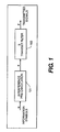
- the GDFE Precoder includes an interference pre-cancellation block 101.
- the interference pre-cancellation helps to ensure that the symbol vector encoded at the k th step will suffer from the interference from (k-1) symbol vectors only.
- Information symbols u are processed by the interference pre-cancellation block 101 to produce filtered vector symbols x.
- the filtered vector symbols x are then passed through a transmit filter 103 denoted by matrix B to produce transmitted signals y.
- a technique based on the covariance matrix ( S zz ) corresponding to "Least Favorable Noise” is proposed to compute the GDFE Precoder components. Although, this technique achieves a high degree of system capacity, the computational cost of determining the GDFE Precoder components is effectively prohibitive for a real-time implementation required by most practical systems.
- a technique is used to realize a GDFE Precoder for multi-user (MU) MIMO systems, which significantly reduces the computational cost while resulting in no capacity loss.
- the technique is suitable for improving the performance of various MU-MIMO wireless systems including presently planned future "4G" cellular networks.
- a GDFE Precoder relaxes the requirement for knowledge of the covariance matrix ( S zz ) corresponding to "Least Favorable Noise". This is the key component in conventional design of a GDFE Precoder and requires extensive computational cost. It also provides a uniform framework for realizing a GDFE Precoder. Unlike conventional GDFE Precoder design, the proposed method does not require channel reduction when the Input Covariance Matrix ( S xx ) for downlink channel is rank deficient.
- An aspect of the present invention is directed to a method for configuring a generalized decision feedback equalizer (GDFE) based precoder in a base station of a multi-user multiple-input multiple-output (MU-MIMO) wireless system having k user terminals (UTs), each user terminal (UT) having associated therewith a feedforward filter.
- the method comprises computing a filter matrix C using one of a plurality of alternative formulas of the invention as described below; and, based on the computation of the filter matrix C, computing a transmit filter matrix B for a transmit filter used to process a symbol vector obtained after a decision feedback equalizing stage of the GDFE precoder, computing the feedforward filter matrix F, and computing the interference pre-cancellation matrix G.
- Another aspect of the invention is directed to a GDFE based precoder in a base station of a MU-MIMO wireless system having k user terminals, each user terminal having associated therewith a feedforward filter.
- the GDFE precoder comprises a feedforward path; a feedback path; and an interference pre-cancellation block denoted by I-G disposed in the feedback path, I being an identity matrix, G being an interference pre-cancellation matrix.
- I-G an interference pre-cancellation block denoted by I-G disposed in the feedback path, I being an identity matrix, G being an interference pre-cancellation matrix.
- a feedforward filter matrix F is related to the interference pre-cancellation matrix by a novel expression as described below.
- Yet another aspect of the invention is directed to a GDFE based precoder in a base station of a MU-MIMO wireless system having k user terminals, each user terminal having associated therewith a feedforward filter.
- the GDFE precoder comprises a feedforward path; a feedback path; and an interference pre-cancellation block denoted by I-G disposed in the feedback path, I being an identity matrix, G being an interference pre-cancellation matrix.
- the interference pre-cancellation matrix G in the interference pre-cancellation block is determined by computing a filter matrix C using one of a plurality of alternative formulas of the invention as described below; and, based on the computation of the filter matrix C, computing a transmit filter matrix B for a transmit filter used to process a symbol vector obtained after a decision feedback equalizing stage of the GDFE precoder, computing the feedforward filter matrix F, and computing the interference pre-cancellation matrix G.
- the base station have N antennas and let there be K user terminals (UTs) with L k antennas each.
- H k denote the channel gain matrix of dimensions ⁇ L k x N ⁇ between the BS and the k th UT.
- the combined channel gain matrix between the BS and the K UTs is of dimension ⁇ L x N ⁇ and is given by where the superscript T denotes the matrix transpose.
- u k denote the input symbol vector destined for the k th UT, so that the stacked input vector can be represented as
- the length of u is assumed not to exceed the number of antennas at the BS.
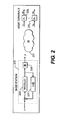
- a functional block diagram is shown of a MU-MIMO system having a base station 210 and user terminals 220 1 -220 k . Each user terminal has associated therewith a feedforward filter F 1 - F k . Communications occur through a channel 231 represented by a channel matrix H.
- the base station includes a GDFE Precoder including a feedforward path and a feedback path.
- a modulo unit 233 produces a stream of filtered vector symbols X , which are filtered by a transmit filter 235 to produce a transmitted signal stream y.
- the symbols X are fed back through an interference pre-cancellation block 237, represented by an interference pre-cancellation matrix G subtracted from the identity matrix I.
- a stream of user symbols u has subtracted therefrom an output signal of the interference pre-cancellation block 237, with the result being applied to the modulo unit 233.
- the GDFE Precoder includes an interference pre-cancellation block denoted by I-G, where G has the structure of a Block Upper Right Triangular matrix. Similar to the THP precoding scheme of reference [2], the triangular structure of the feedback matrix G helps to ensure that the symbol vector encoded at the k th step will suffer from the interference from (k-1) symbol vectors only.
- G km denotes the sub-matrix of G required to pre-cancel interference due to the vector symbol x m from x k .
- the elements of ⁇ k are chosen such that the elements of the resulting vector x k are bounded by the square region of width . This mechanism, while allowing for interference pre-cancellation, also limits the total transmit power.
- the vector y is transmitted by mapping its element to the respective antenna elements of the Base Station.
- the feedforward filter employed by k th UT be denoted by F k , which is a matrix of dimension ⁇ a k x L k ⁇ where a k denotes the length of vector u k .
- the filter B indicates the transmit filter, and noise at k th UT is denoted by n k .
- the matrices ⁇ V , ⁇ are same as defined in (1).
- the input covariance matrix S xx for the downlink channel may be computed by first computing the input covariance matrix D for the equivalent Uplink/Medium Access Channel (MAC) with channel gain matrix H H .
- the capacity achieved by the proposed GDFE method is the same as the capacity achieved by the choice of D for the equivalent Uplink channel.
- a capacity optimal D can be computed using the methodology presented in reference [6].
- a filter matrix C HV ⁇ 1 / 2 H ⁇ HS xx ⁇ H H + S zz - 1 (step 403 in Fig. 4 ).
- F Block Diagonal and G is Block Upper Right Triangular with Identity matrices forming its diagonal block.
- M is unitary matrix; pre-multiplication of M H with C must result in a Block Upper Right Triangular matrix R.
- Compute B V ⁇ 1 / 2 ⁇ M step 407
- Set F BlockDiagonal R step 408
- the BlockDiagonal(.) function extracts submatrices F 1 , F 2 ..., F k of size ⁇ a k x L k ⁇ from the block diagonals of the matrix R as illustrated in Fig. 3 .
- the number of symbols, a k , allotted to the k th UT equals the rank of F k .
- Compute G FR ⁇ step 409 where the superscript t denotes the Moore-Penrose Generalized Inverse.
- the matrix S xx denotes the input covariance matrix for the effective downlink channel matrix [HX].
- the foregoing methods provide a way to improve the spectral efficiency of MU-MIMO systems at computational costs within reasonable bounds.
- the performance improvements are essentially the same as those provided by more computationally complex GDFE Precoders.
- the methods are well-suited to high speed digital cellular telephony, including developing standards such as IMT-Advanced, and other forms of high speed digital communication, including wired communications.
- the foregoing methods may be embodied in various forms and implemented as methods, processes, systems, and components such as integrated circuits.
- the methods are carried out in software executed by a digital signal processor.
Landscapes
- Engineering & Computer Science (AREA)
- Computer Networks & Wireless Communication (AREA)
- Signal Processing (AREA)
- Power Engineering (AREA)
- Radio Transmission System (AREA)
- Mobile Radio Communication Systems (AREA)
Abstract
Description
- The present invention relates to multiple-input multiple-output (MIMO) communications systems. More specifically, the present invention relates to precoder configuration in MIMO systems.
- It is well known that a Generalized Decision Feedback Equalizer (GDFE) based precoder provides the optimal capacity solution for Multi-user Multiple-Input Multiple-Output (MU-MIMO) wireless systems. However, the computational cost of determining various filters associated with the GDFE Precoder is often prohibitive and is not suitable for many practical systems.
- There are several known Precoding techniques which can enable a Base Station (BS) equipped with multiple antennas to send simultaneous data streams to multiple user terminals (UTs) in order to optimize system capacity. In general, Precoding for a MU-MIMO system aims to optimize a certain criterion such as system capacity or bit error rate. Selected references are noted below, together with a description of relevant aspects of the techniques proposed therein.
- Q.H Spencer, A.L. Swindlehurst, and M. Haardt, "Zero-forcing methods for downlink spatial multiplexing in multi-user MIMO channels", IEEE Transactions on Signal Processing, pp. 461-471, Feb. 2004 [1] describes a linear precoding technique, known as Block Diagonalization (BD), which separates out the data streams to different UTs by ensuring that interference spans the Null Space of the victim UT's channel. The BD technique diagonalizes the effective channel matrix so as to create multiple isolated MIMO sub-channels between the BS and the UTs. Although this scheme is simple to implement, it limits system capacity somewhat.
- C. Windpassinger, R.F.H Fischer, T. Vencel, and J.B Huber, "Precoding in multi-antenna and multi-user communications", IEEE Transactions on Wireless Communications, pp. 1305-1316, July 2004 [2] describes a non-linear precoding scheme known as Tomlinson-Harashima Precoding (THP). This scheme relies on successive interference pre-cancellation at the BS. A modulo operation is used to ensure that transmit power is not exceeded. Different from BD, THP triangularizes the effective channel matrix and provides somewhat higher system capacity when compared to BD.
- In W. Yu, "Competition and Cooperation in Multi-User Communication Environments", PhD Dissertation, Stanford University, Feb. 2002 [3] and W. Yu and J. Cioffi, "Sum capacity of Gaussian vector broadcast channels", IEEE Transactions on Information Theory, pp. 1875-1892, Sept. 2004 [4], Wei Yu introduced the GDFE Precoder and showed that it achieves a high degree of system capacity. The basic components of this scheme are illustrated in
Fig. 1 . The GDFE Precoder includes an interference pre-cancellationblock 101. Similar to the THP precoding scheme discussed in reference [2] above, the interference pre-cancellation helps to ensure that the symbol vector encoded at the kth step will suffer from the interference from (k-1) symbol vectors only. Information symbols u are processed by the interference pre-cancellationblock 101 to produce filtered vector symbols x. - The filtered vector symbols x are then passed through a
transmit filter 103 denoted by matrix B to produce transmitted signals y. In reference [3] and [4], a technique based on the covariance matrix (S zz ) corresponding to "Least Favorable Noise" is proposed to compute the GDFE Precoder components. Although, this technique achieves a high degree of system capacity, the computational cost of determining the GDFE Precoder components is effectively prohibitive for a real-time implementation required by most practical systems. - X. Shao, J. Yuan and P. Rapajic, "Precoder design for MIMO broadcast channels", IEEE International Conference on Communications (ICC), pp. 788-794, May 2005 [5] proposes a different precoding technique which achieves a capacity close to the theoretical maximum system capacity. The proposed method is computationally less complex compared to the GDFE Precoder technique. However, the proposed method allocates equal power to all data streams, which may not be an effective technique for practical systems using a finite number of quantized bit-rates. Also, the proposed technique is limited to invertible channel matrices, which may not always be the case.
- N. Jindal, W. Rhee, S. Vishwanath, S.A. Jafar, and A. Goldsmith, "Sum Power Iterative Water-filling for Multi-Antenna Gaussian Broadcast Channels", IEEE Transactions on Information Theory, pp. 1570-1580, April 2005 [6] derives a very useful result referred to as the MAC/BC (multiple access channel/broadcast channel) duality.; and Wei Yu, DIMACS Series in Discrete Mathematics and Theoretical Computer Science, Vol. 66, "Advances in Network Information Theory," pp. 159-147 [7] develops the concept of least favorable noise.
- A technique is used to realize a GDFE Precoder for multi-user (MU) MIMO systems, which significantly reduces the computational cost while resulting in no capacity loss. The technique is suitable for improving the performance of various MU-MIMO wireless systems including presently planned future "4G" cellular networks.
- The described implementation of a GDFE Precoder relaxes the requirement for knowledge of the covariance matrix (S zz ) corresponding to "Least Favorable Noise". This is the key component in conventional design of a GDFE Precoder and requires extensive computational cost. It also provides a uniform framework for realizing a GDFE Precoder. Unlike conventional GDFE Precoder design, the proposed method does not require channel reduction when the Input Covariance Matrix (S xx ) for downlink channel is rank deficient.
- The described implementation of a GDFE Precoder achieves significant improvement in computational cost over conventional GDFE Precoders.
- An aspect of the present invention is directed to a method for configuring a generalized decision feedback equalizer (GDFE) based precoder in a base station of a multi-user multiple-input multiple-output (MU-MIMO) wireless system having k user terminals (UTs), each user terminal (UT) having associated therewith a feedforward filter. The method comprises computing a filter matrix C using one of a plurality of alternative formulas of the invention as described below; and, based on the computation of the filter matrix C, computing a transmit filter matrix B for a transmit filter used to process a symbol vector obtained after a decision feedback equalizing stage of the GDFE precoder, computing the feedforward filter matrix F, and computing the interference pre-cancellation matrix G.
- Another aspect of the invention is directed to a GDFE based precoder in a base station of a MU-MIMO wireless system having k user terminals, each user terminal having associated therewith a feedforward filter. The GDFE precoder comprises a feedforward path; a feedback path; and an interference pre-cancellation block denoted by I-G disposed in the feedback path, I being an identity matrix, G being an interference pre-cancellation matrix. A feedforward filter matrix F is related to the interference pre-cancellation matrix by a novel expression as described below.
- Yet another aspect of the invention is directed to a GDFE based precoder in a base station of a MU-MIMO wireless system having k user terminals, each user terminal having associated therewith a feedforward filter. The GDFE precoder comprises a feedforward path; a feedback path; and an interference pre-cancellation block denoted by I-G disposed in the feedback path, I being an identity matrix, G being an interference pre-cancellation matrix. The interference pre-cancellation matrix G in the interference pre-cancellation block is determined by computing a filter matrix C using one of a plurality of alternative formulas of the invention as described below; and, based on the computation of the filter matrix C, computing a transmit filter matrix B for a transmit filter used to process a symbol vector obtained after a decision feedback equalizing stage of the GDFE precoder, computing the feedforward filter matrix F, and computing the interference pre-cancellation matrix G.
- Additional features and benefits of the present invention will become apparent from the detailed description, figures and claims set forth below.
- The present invention will be understood more fully from the detailed description given below and from the accompanying drawings of various embodiments of the invention, which, however, should not be taken to limit the invention to the specific embodiments, but are for explanation and understanding only.
-
Fig. 1 is a block diagram of a known GDFE Precoder; -
Fig. 2 is a block of a communications system using GDFE Precoding; -
Fig. 3 is a block diagram of configuring feedforward filter of GDFE Precoder; -
Fig. 4 is a flowchart of configuring a GDFE Precoder; - In the following, the system model and relevant prior art are first described in sub-section A, followed in sub-section B by a description of implementations of a GDFE Precoder.
- Those of ordinary skill in the art will realize that the following detailed description of the present invention is illustrative only and is not intended to be in any way limiting. Other embodiments of the present invention will readily suggest themselves to such skilled persons having the benefit of this disclosure. It will be apparent to one skilled in the art that these specific details may not be required to practice to present invention. In other instances, well-known circuits and devices are shown in block diagram form to avoid obscuring the present invention. In the following description of the embodiments, substantially the same parts are denoted by the same reference numerals.
- First, the system model and notations used thereafter are set forth. Let the base station (BS) have N antennas and let there be K user terminals (UTs) with Lk antennas each. The sum of antennas at UTs is denoted as
 where the superscript T denotes the matrix transpose.
- Let uk denote the input symbol vector destined for the kth UT, so that the stacked input vector can be represented asThe length of u is assumed not to exceed the number of antennas at the BS. Also, assume the additional constraint that S uu = E[uu H ] = I, where E[.] indicates the time average of its argument, the superscript H denotes the conjugate transpose and I denotes the identity matrix.

- Referring to
Fig. 2 , a functional block diagram is shown of a MU-MIMO system having abase station 210 and user terminals 2201-220k. Each user terminal has associated therewith a feedforward filter F 1-F k. Communications occur through achannel 231 represented by a channel matrix H. The base station includes a GDFE Precoder including a feedforward path and a feedback path. In the feedforward path, a modulounit 233 produces a stream of filtered vector symbols X, which are filtered by a transmitfilter 235 to produce a transmitted signal stream y. In the feedback path, the symbols X are fed back through aninterference pre-cancellation block 237, represented by an interference pre-cancellation matrix G subtracted from the identity matrix I. A stream of user symbols u has subtracted therefrom an output signal of theinterference pre-cancellation block 237, with the result being applied to themodulo unit 233. - Other aspects/parameters related to this system model are described below:
- 1). Interference Pre-cancellation Matrix (G):
- This matrix is used at the transmitter at Interference Pre-cancellation Stage of the GDFE Precoder as shown in
Fig. 2 . The main purpose of this matrix is to process input symbol vector u for interference pre-cancellation purposes. Its structure is that of an Upper Right Triangular matrix with block diagonal sub-matrices being identity matrices each of size ak.
- This matrix is used at the transmitter at Interference Pre-cancellation Stage of the GDFE Precoder as shown in
- 2). Input Covariance Matrix for Downlink Channel (S xx ): It is defined as S xx = E[xx H ] and satisfies the transmit power constraint, i.e., trace(S xx ) ≤ Pt , where Pt denotes the total available transmit power and trace(.) indicates the sum of diagonal elements of the matrix argument. The input covariance matrix for the downlink channel represents dependencies of symbols transmitted from different ones of said N transmit antennas; a sum of diagonal matrix elements represents an intended total transmit power from the N transmit antennas. In the following text, S xx will be represented using its Eigen Value Decomposition (EVD) as:

where V is a unitary matrix and Σ is a diagonal matrix with non-negative entries. - 3). Transmit Filter (B): This matrix is used to process the symbol vector x obtained after the DFE stage of GDFE Precoder as shown in
Fig. 2 . It is denoted by the following equation:
where M is a unitary matrix and the matrices {V,Σ} are same as defined in (1). - 4). Least Favorable Noise Covariance Matrix (S zz ): This may be regarded as the noise covariance matrix that results in the minimum system capacity when full coordination among all UTs is assumed. This is a positive definite Hermitian Matrix whose block diagonal sub-matrices are identity matrices of size ak. This is defined in a similar fashion to that shown in Eq. (67) of reference [4].
- 5). Input Covariance Matrix for Equivalent Uplink Channel (D): It is defined similar to the Equation (3.6) of reference [7] as the correlation among the symbols of the input vector for the equivalent Uplink/Medium Access Channel (MAC) with channel matrix H H . The structure of matrix D is that of a block diagonal matrix and satisfies the transmit power constraint, i.e., trace(D) ≤ Pt , where Pt denotes the total available transmit power. Each block diagonal sub-matrix of D represents the input covariance matrix for a particular UT in the Uplink channel. A capacity optimal D can be computed using the methodology presented in reference [6].
- As shown in
Fig. 2 , the GDFE Precoder includes an interference pre-cancellation block denoted by I-G, where G has the structure of a Block Upper Right Triangular matrix. Similar to the THP precoding scheme of reference [2], the triangular structure of the feedback matrix G helps to ensure that the symbol vector encoded at the kth step will suffer from the interference from (k-1) symbol vectors only. The x k th sub-vector ofis generated using the following relationship:

where G km denotes the sub-matrix of G required to pre-cancel interference due to the vector symbol x m from x k. These sub-vectors are generated in the reverse order, with x K being the first generated vector and x1 being the last one. An example of the structure of the matrix G for a 3 UT scenario is shown below
- In this particular example, x 3 is generated first, followed by x2 from which interference due to x 3 is pre-subtracted using the sub-matrix G 23. Lastly, x 1 is generated after pre-subtraction of interference due to x 2 and x 3. Also, each complex element of vector α k in (3) is chosen from the following set:

- The elements of α k are chosen such that the elements of the resulting vector x k are bounded by the square region of width. This mechanism, while allowing for interference pre-cancellation, also limits the total transmit power.

- The vector x is then passed through a transmit filter B to yield a vector y given by the following relationship:
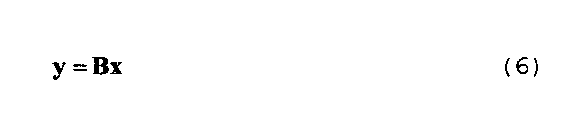
- The vector y is transmitted by mapping its element to the respective antenna elements of the Base Station.
- Let the feedforward filter employed by kth UT be denoted by F k, which is a matrix of dimension {ak x Lk} where ak denotes the length of vector u k. Now, the received baseband vector corresponding to the kth UT is given by

where x is the symbol vector derived from input symbol vector u after an interference pre-cancellation step as shown inFig. 2 . The filter B indicates the transmit filter, and noise at kth UT is denoted by n k. The stacked received basedband vector corresponding to all K UTs can be represented as
where, F = diag(F 1,F 2,...F K ) is a block diagonal matrix representing the feedforward filter and n represents stacked noise vector. - In the following, different methods are presented to compute matrices B, G and F as defined earlier. One method assumes the knowledge of S zz whereas other methods provide ways to compute GDFE matrices without any knowledge of S zz .
- Unlike prior methods, in the present method the feedforward filter, F, is expressed as:

where the "Least Favorable Noise," S zz , may be regarded as the noise covariance matrix that results in the minimum system capacity when there is full coordination among all UTs. S zz may be computed using the technique described in reference [4]. The matrices {V,Σ} are same as defined in (1). - The input covariance matrix S xx for the downlink channel may be computed by first computing the input covariance matrix D for the equivalent Uplink/Medium Access Channel (MAC) with channel gain matrix H H . The capacity achieved by the proposed GDFE method is the same as the capacity achieved by the choice of D for the equivalent Uplink channel. A capacity optimal D can be computed using the methodology presented in reference [6]. The input covariance matrix S xx for the downlink channel can then be computed using the following equation given in reference [7]:

where for a given total transmit power Pt, the scalar variable λ can be computed as:
- Next, referring to
Fig. 4 , a filter matrix C is defined as:
(step 403 inFig. 4 ). Now, the feedforward filter F can be represented as
- It can be noted that F is Block Diagonal and G is Block Upper Right Triangular with Identity matrices forming its diagonal block. Given that M is unitary matrix; pre-multiplication of M H with C must result in a Block Upper Right Triangular matrix R. Hence, M can be obtained using the QR decomposition (QRD) of C as

(step 406). It must be noted that the QRD is performed in such a way that all non-zero columns of C which span the same vector space contribute to only one column vector in matrix M. Computation of matrices B, G and F is then performed as follows:

The BlockDiagonal(.) function extracts submatrices F 1, F 2..., F k of size {ak x Lk} from the block diagonals of the matrix R as illustrated inFig. 3 . The number of symbols, ak, allotted to the kth UT equals the rank of F k.
where the superscript t denotes the Moore-Penrose Generalized Inverse. - In this method, the use of S zz is avoided for computing the matrix C and subsequently other dependent matrices of GDFE Precoder.
- The expression (12) is rewritten as:
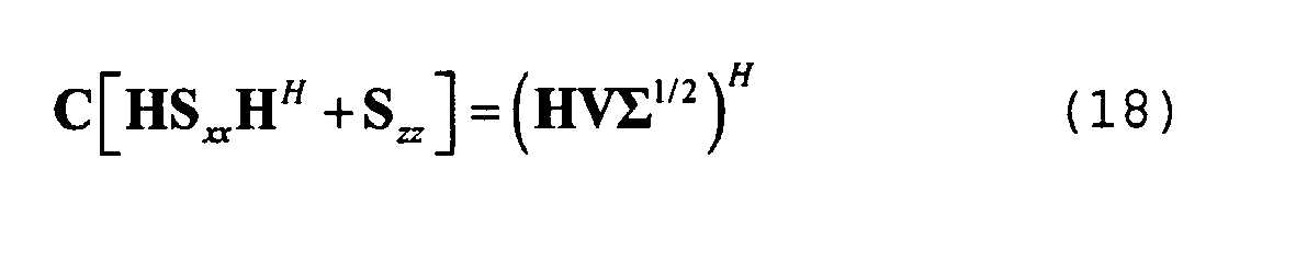
- Next, the expression H H [HS xx H H +S zz ]-1 H=λI given in reference [7] is alternatively expressed as:

where λ is computed using (11). - Next, the expression in (19) is substituted in (18) to obtain the following equality

- Now, for a channel matrix H whose rank is greater than or equal to its number of rows, the matrix C can be uniquely determined as:

(step 404 inFig. 4 ) where the superscript t denotes the Moore-Penrose Generalized Inverse. Furthermore, omitting the scalar operation λ in above expression does not alter the performance of GDFE Precoder. Therefore, following expression can also be used for channels whenever the rank of H is greater than or equal to the number of rows in H:
- For the channel matrix H whose rank is less than its number of rows, the matrix C can be determined by solving the following limit:

where X is an arbitrary matrix with same number of rows as H. The number of columns in X is chosen so that the rank of the resulting matrix [HX] is greater than or equal to the number of rows in H. Here, the matrix Sxx denotes the input covariance matrix for the effective downlink channel matrix [HX]. - The expression in (23) can be simplified using (10) along with some matrix manipulations as

- This expression can be further simplified using matrix inversion identities as

Here the matrix product (HV) † HV in (25) is equal to a diagonal matrix with leading diagonal entries being 1 and the rest of trailing entries being 0. The number of diagonal entries equal to 1 is same as the rank of H. Observing that the rank of the matrix product HV is always greater than or equal to that of Sigma, it can be ensured that the number of trailing zeros in the matrix product (HV) † HV are always less than or equal to those in Σ. - Hence the above expression in (25) can be further simplified as

(step 405 inFig. 4 ). Here it should be noted that expressions (24), (25) and (26) can be used for any arbitrary channel matrix H. However when the rank of channel matrix is greater than or equal to its number of rows, expression in (21) or (22) may be used because of possible computational efficiency. - The following numerical example illustrates the computation of various matrices involved in the design of GDFE Precoder for the case when S zz is known beforehand, i.e. C is computed using equation (12).
- Consider a BS with 4 antennas and 2 users with 2 antennas each, so that channel matrices associated with both the users are of dimension 2x4. Let the overall channel matrix be the following:

- For fixed transmit power of 20, the optimal input covariance matrix S xx for the downlink channel can be computed by first computing the optimal input covariance matrix D for the equivalent Uplink/MAC channel as described in [6] and then using the equation (10) :

- The Eigen Value Decomposition (EVD) of S xx can be computed as:

and
- Also, the "Least Favorable Noise" covariance matrix S zz may be computed using the technique described in reference [4] as

- Following the details outlined in Method-I, the following QR Decomposition is first computed

- Next, the method computes the transmit filter matrix B as

- The effective feedforward filter can be computed as:

- Therefore, the two users employ the following feedforward filters for baseband signal processing as shown in Eq. (7).

- Also, the interference pre-cancellation matrix G can be computed as:

- The following numerical example illustrates the computation of various matrices involved in the design of GDFE Precoder when S zz is unknown. The same system as in Example-1 with transmit power fixed to 20 is assumed so that matrices H, S xx , V, and Σ are given by Equations (27)-(30) respectively.
- Following the details outlined in B.1, compute the matrix C and its QR Decomposition:

- Next, the method computes the transmit filter matrix B as

- Also, the effective feedforward filter is computed as:

- Therefore, the two users employ the following feedforward filters for baseband signal processing as shown in Eq. (7).

- Also, the interference pre-cancellation matrix G is computed as:

- Consider the same system as in previous example but fix the transmit power to 10 instead of 20 as in pervious two examples. In this case, the matrices associated with the GDFE Precoder can be shown to be:

- From Eq. (42), it is apparent that the 2nd column of B is zero, implying that the second element in x1 is assigned 0 transmit power. It is therefore suggested to transmit only 1 symbol to UT-1 and 2 symbols to UT-2, that is set u 1 = [u 11 0] T , u 2 = [u 21 u 22] T so that


and
- The following numerical example illustrates the computation of various matrices involved in the design of a GDFE Precoder when channel matrix H is rectangular. Consider a BS with 4 antennas and 2 users with 3 antennas each, so that channel matrices associated with both the users are of dimension 3x4. The overall channel matrix is non-square, for example:

- Now, for fixed transmit power of 20 the optimal input covariance matrix S xx for the downlink channel can be computed using the MAC/BC duality of reference [6] and is given by:

- The Eigen Value Decomposition (EVD) of S xx can be computed as:

and
- The optimal input covariance matrix D for the equivalent Uplink/MAC channel can be computed using the methods described in reference [6] as,

- Now, matrix C can be computed using Eq. (26) as,

- Next, the method computes the transmit filter matrix B as

- The effective feedforward filter can be computed as:

- Therefore, the two users employ the following feedforward filters for baseband signal processing as shown in Eq. (7).

- It is apparent from Equations 52 and 53, that the first user is assigned only one symbol whereas the second user is assigned 3 symbols. That is, u 1 = [u 11], u 2 = [u 21 u 22 u 23] T so thatThe interference pre-cancellation matrix G can therefore be computed as:


- The foregoing methods provide a way to improve the spectral efficiency of MU-MIMO systems at computational costs within reasonable bounds. The performance improvements are essentially the same as those provided by more computationally complex GDFE Precoders. Thus, the methods are well-suited to high speed digital cellular telephony, including developing standards such as IMT-Advanced, and other forms of high speed digital communication, including wired communications.
- The foregoing methods may be embodied in various forms and implemented as methods, processes, systems, and components such as integrated circuits.
In one typical implementation, the methods are carried out in software executed by a digital signal processor. - While particular embodiments of the present invention have been shown and described, it will be obvious to those skilled in the art that, based upon the teachings herein, changes and modifications may be made without departing from this invention and its broader aspects. Therefore, the appended claims are intended to encompass within their scope all such changes and modifications as are within the true spirit and scope of this invention.
Claims (13)
- A method for processing user symbols with a generalized decision feedback equalizer (GDFE) based precoder (233, 235, 237) in a base station of a multi-user multiple-input multiple-output (MU-MIMO) wireless system having K user terminals (UTs) (2201-220k), each user terminal (UT) having associated therewith a feedforward filter represented by F 1, F 2..., F k, the method comprising:computing a filter matrix C using one of the following expressionswhere V is a unitary matrix, Σ is a diagonal matrix with non-negative entries, and S zz is a least favorable noise covariance matrix,

where S xx is an input covariance matrix for the downlink channel
where I is an identity matrix, H is a channel matrix representing a channel through which communications occur in the wireless system, D is an input covariance matrix for an equivalent Uplink/medium access channel (MAC) in the wireless system which is chosen to be capacity optimal, and λ is a scalar variable for a given total transmit power Pt,
for a channel matrix H whose rank is greater than or equal to its number of rows, where superscript t denotes a Moore-Penrose Generalized Inverse,
for a channel matrix H whose rank is greater than or equal to its number of rows, and
wherein a feedforward filter matrix F is represented by F=GM H C, M is a unitary matrix, and G is an interference pre-cancellation matrix used in a transmitter at an interference pre-cancellation stage of the GDFE precoder;
computing the matrix M using QR decomposition (QRD) of C as
computing the feedforward filter matrix F as
where the BlockDiagonal(.) function extracts submatrices F 1, F 2..., F k of size {ak x Lk} from block diagonals of the matrix R, and ak is a number of symbols allotted to the kth user terminal (UT) and equals the rank of F k;
computing the interference pre-cancellation matrix G as
where superscript † denotes a Moore-Penrose Generalized Inverse; and
processing user symbols by a decision feedback equalizing stage of the GDFE precoder to produce filtered vector symbols. - The method of claim 1, further comprising:subtracting the interference pre-cancellation matrix G from an identity matrix I to obtain an interference pre-cancellation block,wherein the GDFE precoder includes a feedforward path and a feedback path, a stream of the filtered vector symbols X are produced by a modulo unit disposed in the feedforward path and are fed back through the interference pre-cancellation block disposed in the feedback path.
- The method of claim 2, further comprising:subtracting from a stream of user symbols an output signal of the interference pre-cancellation block and applying a result of the subtracting to the modulo unit in the feedforward path.
- The method of claim 2, further comprising:computing a transmit filter matrix B for a transmit filter used to process a symbol vector obtained after the decision feedback equalizing stage of the GDFE precoder
 filtering the stream of filtered vector symbols X produced by the modulo unit disposed in the feedforward path by the transmit filter represented by the transmit filter matrix B.
 - The method of claim 4, further comprising:directing an output of the transmit filter to the channel represented by the channel matrix H through which communications occur in the wireless system with the user terminals.
- A generalized decision feedback equalizer (GDFE) based precoder (233, 235, 237) in a base station of a multi-user multiple-input multiple-output (MU-MIMO) wireless system having K user terminals (UTs) (2201-220k), each user terminal (UT) having associated therewith a feedforward filter represented by F 1, F 2..., F k, the GDFE precoder comprising:a feedforward path;a feedback path; andan interference pre-cancellation block denoted by I-G disposed in the feedback path, I being an identity matrix, G being an interference pre-cancellation matrix;wherein a feedforward filter matrix F is

where the BlockDiagonal(.) function extracts submatrices F 1, F 2..., F k of size {ak x Lk} from block diagonals of a matrix R, and ak is a number of symbols allotted to the kth user terminal (UT) and equals the rank of F k; and
wherein
where M is a unitary matrix, V is a unitary matrix, Σ is a diagonal matrix with non-negative entries, and Szz is a least favorable noise covariance matrix,
where S xx is an input covariance matrix for the downlink channel
where I is an identity matrix, H is a channel matrix representing a channel through which communications occur in the wireless system, D is an input covariance matrix for an equivalent Uplink/medium access channel (MAC) in the wireless system which is chosen to be capacity optimal, and λ is a scalar variable for a given total transmit power Pt,
- The GDFE precoder (233, 235, 237) of claim 6,
wherein the interference pre-cancellation matrix G in the interference pre-cancellation block is determined by
computing a filter matrix C using one of the following expressions

for a channel matrix H whose rank is greater than or equal to its number of rows, where superscript t denotes a Moore-Penrose Generalized Inverse, and
wherein the feedforward filter matrix F is represented by F = GM H C;
computing the matrix M using QR decomposition (QRD) of C as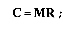
computing the feedforward filter matrix F as
where the BlockDiagonal(.) function extracts submatrices F 1, F 2..., F k of size {ak x Lk} from block diagonals of the matrix R, and ak is the number of symbols allotted to the kth user terminal (UT) and equals the rank of F k; and
computing the interference pre-cancellation matrix G as
where superscript † denotes a Moore-Penrose Generalized Inverse. - A generalized decision feedback equalizer (GDFE) based precoder (233, 235, 237) in a base station (210) of a multi-user multiple-input multiple-output (MU-MIMO) wireless system having k user terminals (UTs) (2201-220k), each user terminal (UT) having associated therewith a feedforward filter represented by F 1, F 2..., F k, the GDFE precoder comprising:a feedforward path;a feedback path; andan interference pre-cancellation block denoted by I-G disposed in the feedback path, I being an identity matrix, G being an interference pre-cancellation matrix;wherein the interference pre-cancellation matrix G in the interference pre-cancellation block is determined by
computing a filter matrix C using one of the following expressions
where V is a unitary matrix, Σ is a diagonal matrix with non-negative entries, and S zz is a least favorable noise covariance matrix,
where S xx is an input covariance matrix for the downlink channel
where I is an identity matrix, H is a channel matrix representing a channel through which communications occur in the wireless system, D is an input covariance matrix for an equivalent Uplink/medium access channel (MAC) in the wireless system which is chosen to be capacity optimal, and λ is a scalar variable for a given total transmit power Pt,
for a channel matrix H whose rank is greater than or equal to its number of rows, where superscript t denotes a Moore-Penrose Generalized Inverse,
for a channel matrix H whose rank is greater than or equal to its number of rows, and
wherein a feedforward filter matrix F is represented by F = GM H C, M is a unitary matrix, and G is an interference pre-cancellation matrix used in a transmitter at an interference pre-cancellation stage of the GDFE precoder;
computing the matrix M using QR decomposition (QRD) of C as
computing the feedforward filter matrix F as
where the BlockDiagonal(.) function extracts submatrices F 1, F 2..., F k of size {ak x Lk} from block diagonals of the matrix R, and ak is a number of symbols allotted to the kth user terminal (UT) and equals the rank of F k; and
computing the interference pre-cancellation matrix G as
where superscript † denotes a Moore-Penrose Generalized Inverse. - The GDFE precoder (233, 235, 237) of claim 6 or 8, further comprising:a modulo unit disposed in the feedforward path to produce a stream of filtered vector symbols X which are fed back through the interference pre-cancellation block disposed in the feedback path.
- The GDFE precoder (233, 235, 237) of claim 9,
wherein an output signal of the interference pre-cancellation block is subtracted from a stream of user symbols and applied to the modulo unit in the feedforward path. - The GDFE precoder (233, 235, 237) of claim 9, further comprising:a transmit filter represented by a transmit filter matrix B for filtering the stream of filtered vector symbols X produced by the modulo unit disposed in the feedforward path;wherein the transmit filter matrix B is

- A MU-MIMO wireless system comprising:a base station (210) including the GDFE precoder (233, 235, 237) of claim 11;a plurality of K user terminals (2201-220k); anda channel, represented by the channel matrix H through which communications occur in the wireless system with the user terminals, to receive an output of the transmit filter.
- The MU-MIMO wireless system of claim 12,
wherein the wireless system includes N antennas and the kth user terminal (UT) (220k) has Lk antennas,
wherein a sum of antennas at the UTs is denoted as L=Ek=1 k Lk,
wherein H k denotes a channel gain matrix of dimensions {Lk x N} between the base station and the kth UT,
wherein a combined channel gain matrix between the base station and the K UTs is of dimension {L x N} and is given by the channel matrix
where the superscript T denotes the matrix transpose.
Applications Claiming Priority (1)
| Application Number | Priority Date | Filing Date | Title |
|---|---|---|---|
| US12/401,711 US8175189B2 (en) | 2009-03-11 | 2009-03-11 | Fast generalized decision feedback equalizer precoder implementation for multi-user multiple-input multiple-output wireless transmission systems |
Publications (2)
| Publication Number | Publication Date |
|---|---|
| EP2228956A2 true EP2228956A2 (en) | 2010-09-15 |
| EP2228956A3 EP2228956A3 (en) | 2014-09-17 |
Family
ID=42320677
Family Applications (1)
| Application Number | Title | Priority Date | Filing Date |
|---|---|---|---|
| EP10002431.4A Withdrawn EP2228956A3 (en) | 2009-03-11 | 2010-03-09 | Fast generalized decision feedback equalizer precoder implementation for multi-user multiple-input multiple-output wireless transmission systems |
Country Status (4)
| Country | Link |
|---|---|
| US (3) | US8175189B2 (en) |
| EP (1) | EP2228956A3 (en) |
| JP (2) | JP5524657B2 (en) |
| CN (1) | CN101841396B (en) |
Cited By (1)
| Publication number | Priority date | Publication date | Assignee | Title |
|---|---|---|---|---|
| WO2011028646A3 (en) * | 2009-09-04 | 2011-04-28 | Hitachi, Ltd. | Generalized decision feedback equalizer precoder with receiver beamforming for matrix calculations in multi-user multiple-input multiple-output wireless transmission systems |
Families Citing this family (11)
| Publication number | Priority date | Publication date | Assignee | Title |
|---|---|---|---|---|
| US7602855B2 (en) * | 2005-04-01 | 2009-10-13 | Interdigital Technology Corporation | Method and apparatus for singular value decomposition of a channel matrix |
| US8175189B2 (en) * | 2009-03-11 | 2012-05-08 | Hitachi, Ltd. | Fast generalized decision feedback equalizer precoder implementation for multi-user multiple-input multiple-output wireless transmission systems |
| JP5546041B2 (en) * | 2009-04-27 | 2014-07-09 | シャープ株式会社 | Interference suppression radio communication system and interference suppression radio communication apparatus |
| CN102598523B (en) * | 2009-09-04 | 2014-12-17 | 株式会社日立制作所 | Tomlinson Harashima precoding with additional receiver processing in multi-user MIMO wireless transmission systems |
| US8483265B2 (en) * | 2009-09-04 | 2013-07-09 | Hitachi, Ltd. | Generalized decision feedback equalizer precoder with input covariance matrix calculation for multi-user multiple-input multiple-output wireless transmission systems |
| KR101726864B1 (en) * | 2009-10-23 | 2017-04-13 | 한국전자통신연구원 | Mu-mimo method in wlan system, access point and station for mu-mimo |
| WO2012141384A1 (en) * | 2011-04-14 | 2012-10-18 | 엘지전자 주식회사 | Method for suppressing interference of terminal in multiple input multiple output wireless communication system and apparatus therefor |
| KR102242053B1 (en) | 2015-02-02 | 2021-04-19 | 엘지이노텍 주식회사 | Method of forming a touch panel |
| US9647736B1 (en) * | 2015-03-05 | 2017-05-09 | Quantenna Communications, Inc. | Compressed training for massive MU-MIMO in a wireless local area network |
| KR101915901B1 (en) | 2017-06-26 | 2018-11-06 | 연세대학교 산학협력단 | Transmitting/receiving apparatus and method in swipt system using precoding scheme based on slinr |
| KR102695582B1 (en) * | 2019-07-23 | 2024-08-14 | 삼성전자주식회사 | Method for generating precoder and precoder generating device in multi user multiple input and multiple output communication system |
Family Cites Families (20)
| Publication number | Priority date | Publication date | Assignee | Title |
|---|---|---|---|---|
| US6597745B1 (en) | 1999-04-06 | 2003-07-22 | Eric M. Dowling | Reduced complexity multicarrier precoder |
| RU2304352C2 (en) * | 2001-11-29 | 2007-08-10 | Квэлкомм Инкорпорейтед | Mode and an arrangement for definition of logarithmical likelihood ratio with preliminary coding |
| US7130342B2 (en) * | 2002-12-27 | 2006-10-31 | Motorola, Inc. | Wireless receiver and method employing forward/backward recursive covariance based filter coefficient generation |
| WO2005081443A1 (en) * | 2004-02-25 | 2005-09-01 | Ntt Docomo, Inc. | Apparatus and method for sequence estimation using multiple-input multiple -output filtering |
| WO2006008565A1 (en) | 2004-06-18 | 2006-01-26 | Nokia Corporation | Frequency domain equalization of frequency-selective mimo channels |
| WO2006018702A1 (en) * | 2004-08-13 | 2006-02-23 | Agency For Science, Technology And Research | Method for equalizing a digital signal and equalizer |
| WO2006021224A1 (en) | 2004-08-24 | 2006-03-02 | Ntt Docomo, Inc. | Precoder and method for precoding an input sequence to obtain a transmit sequence |
| WO2006052890A1 (en) | 2004-11-05 | 2006-05-18 | University Of Florida Research Foundation, Inc. | Uniform channel decomposition for mimo communications |
| CN1835425A (en) * | 2005-03-16 | 2006-09-20 | 松下电器产业株式会社 | Self-adaptive modulation method based on multi-user precode |
| JP5632124B2 (en) | 2005-03-18 | 2014-11-26 | サーチ エンジン テクノロジーズ リミテッド ライアビリティ カンパニー | Rating method, search result sorting method, rating system, and search result sorting system |
| US7813420B2 (en) * | 2005-06-02 | 2010-10-12 | Adaptive Spectrum And Signal Alignment, Inc. | Adaptive GDFE |
| GB0519749D0 (en) * | 2005-07-08 | 2005-11-09 | Koninkl Philips Electronics Nv | Transmission over a multiple input multiple output broadcast channel (MIMO-BC) |
| US7561633B2 (en) | 2005-07-13 | 2009-07-14 | Leanics Corporation | System and method for MIMO equalization for DSP transceivers |
| US7580445B2 (en) * | 2005-08-22 | 2009-08-25 | Nec Laboratories America, Inc. | Nonlinear precoding in code-division multiple access communication system |
| US7769100B2 (en) * | 2005-12-10 | 2010-08-03 | Electronics And Telecommunications Research Institute | Method and apparatus for cancellation of cross-talk signals using multi-dimensional coordination and vectored transmission |
| US8331425B2 (en) * | 2006-02-28 | 2012-12-11 | Kyocera Corporation | Apparatus, system and method for providing a multiple input/multiple output (MIMO) channel interface |
| KR100959645B1 (en) * | 2007-10-31 | 2010-05-26 | 한국전자통신연구원 | Transmitting / receiving method of multi-user multi-input / output system |
| CN101552633A (en) * | 2008-04-02 | 2009-10-07 | 株式会社Ntt都科摩 | Multiple-input and multiple-output precoding method and device |
| US8175189B2 (en) * | 2009-03-11 | 2012-05-08 | Hitachi, Ltd. | Fast generalized decision feedback equalizer precoder implementation for multi-user multiple-input multiple-output wireless transmission systems |
| US8483265B2 (en) * | 2009-09-04 | 2013-07-09 | Hitachi, Ltd. | Generalized decision feedback equalizer precoder with input covariance matrix calculation for multi-user multiple-input multiple-output wireless transmission systems |
-
2009
- 2009-03-11 US US12/401,711 patent/US8175189B2/en not_active Expired - Fee Related
-
2010
- 2010-03-09 EP EP10002431.4A patent/EP2228956A3/en not_active Withdrawn
- 2010-03-10 JP JP2010052547A patent/JP5524657B2/en not_active Expired - Fee Related
- 2010-03-11 CN CN201010136250XA patent/CN101841396B/en not_active Expired - Fee Related
-
2012
- 2012-04-16 US US13/447,415 patent/US8571138B2/en not_active Expired - Fee Related
-
2013
- 2013-09-26 US US14/037,743 patent/US9210013B2/en not_active Expired - Fee Related
-
2014
- 2014-04-10 JP JP2014081233A patent/JP5745130B2/en not_active Expired - Fee Related
Non-Patent Citations (7)
| Title |
|---|
| C. WINDPASSINGER; R.F.H FISCHER; T. VENCEL; J.B HUBER: "Precoding in multi-antenna and multi-user communications", IEEE TRANSACTIONS ON WIRELESS COMMUNICATIONS, 7000420, pages 1305 - 1316 |
| N. JINDAL; W. RHEE; S. VISHWANATH; S.A. JAFAR; A. GOLDSMITH: "Sum Power Iterative Water- filling for Multi-Antenna Gaussian Broadcast Channels", IEEE TRANSACTIONS ON INFORMATION THEORY, 4000520, pages 1570 - 1580 |
| Q.H SPENCER; A.L. SWINDLEHURST; M. HAARDT: "Zero-forcing methods for downlink spatial multiplexing in multi-user MIMO channels", IEEE TRANSACTIONS ON SIGNAL PROCESSING, 2000420, pages 461 - 471 |
| W. YU: "PhD Dissertation", 2000220, STANFORD UNIVERSITY, article "Competition and Cooperation in Multi-User Communication Environments" |
| W. YU; J. CIOFFI: "Sum capacity of Gaussian vector broadcast channels", IEEE TRANSACTIONS ON INFORMATION THEORY, 9000420, pages 1875 - 1892 |
| WEI YU: "DIMACS Series in Discrete Mathematics and Theoretical Computer Science", ADVANCES IN NETWORK INFORMATION THEORY, vol. 66, pages 159 - 147 |
| X. SHAO; J. YUAN; P. RAPAJIC: "Precoder design for MIMO broadcast channels", IEEE INTERNATIONAL CONFERENCE ON COMMUNICATIONS, 5000520, pages 788 - 794 |
Cited By (2)
| Publication number | Priority date | Publication date | Assignee | Title |
|---|---|---|---|---|
| WO2011028646A3 (en) * | 2009-09-04 | 2011-04-28 | Hitachi, Ltd. | Generalized decision feedback equalizer precoder with receiver beamforming for matrix calculations in multi-user multiple-input multiple-output wireless transmission systems |
| US8396107B2 (en) | 2009-09-04 | 2013-03-12 | Hitachi Ltd. | Generalized decision feedback equalizer precoder with receiver beamforming for matrix calculations in multi-user multiple-input multiple-output wireless transmission systems |
Also Published As
| Publication number | Publication date |
|---|---|
| JP5524657B2 (en) | 2014-06-18 |
| CN101841396A (en) | 2010-09-22 |
| CN101841396B (en) | 2013-06-19 |
| US8175189B2 (en) | 2012-05-08 |
| JP2010213282A (en) | 2010-09-24 |
| JP5745130B2 (en) | 2015-07-08 |
| EP2228956A3 (en) | 2014-09-17 |
| US20100232494A1 (en) | 2010-09-16 |
| US20120201200A1 (en) | 2012-08-09 |
| US8571138B2 (en) | 2013-10-29 |
| US9210013B2 (en) | 2015-12-08 |
| JP2014158277A (en) | 2014-08-28 |
| US20140029662A1 (en) | 2014-01-30 |
Similar Documents
| Publication | Publication Date | Title |
|---|---|---|
| US8175189B2 (en) | Fast generalized decision feedback equalizer precoder implementation for multi-user multiple-input multiple-output wireless transmission systems | |
| US8396107B2 (en) | Generalized decision feedback equalizer precoder with receiver beamforming for matrix calculations in multi-user multiple-input multiple-output wireless transmission systems | |
| US8483265B2 (en) | Generalized decision feedback equalizer precoder with input covariance matrix calculation for multi-user multiple-input multiple-output wireless transmission systems | |
| US8451944B2 (en) | Tomlinson harashima precoding with additional receiver processing in a multi-user multiple-input multiple-output wireless transmission system | |
| US8249186B2 (en) | Method and apparatus for singular value decomposition of a channel matrix | |
| Boroujerdi et al. | Low-complexity statistically robust precoder/detector computation for massive MIMO systems | |
| US20100246715A1 (en) | Wireless communication method and apparatus | |
| US20150215009A1 (en) | System and Method for Early Termination in Iterative Null-Space Directed Singular Value Decomposition for MIMO | |
| EP4128558B1 (en) | Multi-user pre-coding | |
| Maboud Sanaie et al. | Performance analysis of multicell massive MIMO THP with pilot contamination | |
| EP4128559B1 (en) | Multi-user precoding | |
| Gaur | A practical algorithm for realizing GDFE precoder for multiuser MIMO systems | |
| Gaur et al. | A Near-Capacity GDFE-Like Precoder with Reduced Feedback Overhead for MIMO Broadcast Channel |
Legal Events
| Date | Code | Title | Description |
|---|---|---|---|
| PUAI | Public reference made under article 153(3) epc to a published international application that has entered the european phase |
Free format text: ORIGINAL CODE: 0009012 |
|
| 17P | Request for examination filed |
Effective date: 20100331 |
|
| AK | Designated contracting states |
Kind code of ref document: A2 Designated state(s): AT BE BG CH CY CZ DE DK EE ES FI FR GB GR HR HU IE IS IT LI LT LU LV MC MK MT NL NO PL PT RO SE SI SK SM TR |
|
| AX | Request for extension of the european patent |
Extension state: AL BA ME RS |
|
| PUAL | Search report despatched |
Free format text: ORIGINAL CODE: 0009013 |
|
| AK | Designated contracting states |
Kind code of ref document: A3 Designated state(s): AT BE BG CH CY CZ DE DK EE ES FI FR GB GR HR HU IE IS IT LI LT LU LV MC MK MT NL NO PL PT RO SE SI SK SM TR |
|
| AX | Request for extension of the european patent |
Extension state: AL BA ME RS |
|
| RIC1 | Information provided on ipc code assigned before grant |
Ipc: H04L 25/03 20060101AFI20140811BHEP |
|
| STAA | Information on the status of an ep patent application or granted ep patent |
Free format text: STATUS: THE APPLICATION HAS BEEN WITHDRAWN |
|
| 18W | Application withdrawn |
Effective date: 20160127 |