EP2228755A1 - Non-contact ic medium communication device - Google Patents
Non-contact ic medium communication device Download PDFInfo
- Publication number
- EP2228755A1 EP2228755A1 EP08856767A EP08856767A EP2228755A1 EP 2228755 A1 EP2228755 A1 EP 2228755A1 EP 08856767 A EP08856767 A EP 08856767A EP 08856767 A EP08856767 A EP 08856767A EP 2228755 A1 EP2228755 A1 EP 2228755A1
- Authority
- EP
- European Patent Office
- Prior art keywords
- signal level
- contact
- identification information
- medium
- reception
- Prior art date
- Legal status (The legal status is an assumption and is not a legal conclusion. Google has not performed a legal analysis and makes no representation as to the accuracy of the status listed.)
- Granted
Links
- 238000004891 communication Methods 0.000 title claims abstract description 25
- 239000002131 composite material Substances 0.000 claims abstract description 19
- 238000000034 method Methods 0.000 claims abstract description 17
- 230000008569 process Effects 0.000 claims description 9
- 238000001514 detection method Methods 0.000 description 20
- 230000004044 response Effects 0.000 description 15
- 230000005540 biological transmission Effects 0.000 description 6
- 230000007423 decrease Effects 0.000 description 2
- 230000000694 effects Effects 0.000 description 2
- 239000000284 extract Substances 0.000 description 2
- 230000006870 function Effects 0.000 description 2
- 238000012886 linear function Methods 0.000 description 2
- 230000008901 benefit Effects 0.000 description 1
- 230000015572 biosynthetic process Effects 0.000 description 1
- 238000004364 calculation method Methods 0.000 description 1
- 238000000605 extraction Methods 0.000 description 1
- 238000003786 synthesis reaction Methods 0.000 description 1
- 230000032258 transport Effects 0.000 description 1
Images


Classifications
-
- G—PHYSICS
- G01—MEASURING; TESTING
- G01S—RADIO DIRECTION-FINDING; RADIO NAVIGATION; DETERMINING DISTANCE OR VELOCITY BY USE OF RADIO WAVES; LOCATING OR PRESENCE-DETECTING BY USE OF THE REFLECTION OR RERADIATION OF RADIO WAVES; ANALOGOUS ARRANGEMENTS USING OTHER WAVES
- G01S3/00—Direction-finders for determining the direction from which infrasonic, sonic, ultrasonic, or electromagnetic waves, or particle emission, not having a directional significance, are being received
- G01S3/02—Direction-finders for determining the direction from which infrasonic, sonic, ultrasonic, or electromagnetic waves, or particle emission, not having a directional significance, are being received using radio waves
- G01S3/14—Systems for determining direction or deviation from predetermined direction
-
- H04B5/48—
Definitions
- the present invention relates to a non-contact IC medium communication device, for example, which detects a non-contact IC medium within a desired area, a method thereof, a program thereof, and a computer-readable storage medium storing the program.
- Non-contact IC media capable of performing communication of information stored therein in a noncontact manner are conventionally utilized.
- Such non-contact IC media include a medium using a UHF band available for long-distance communication.
- a single-element patch antenna is often used as an antenna for communicating with the non-contact IC medium using the UHF band.
- the single-element patch antenna has a half-power width (beamwidth) as broad as about 70 and therefore has the advantage of reading information from the non-contact IC media in a broad area.
- non-contact IC medium within a specific area need to be read.
- cases include, for example, a case that, under the situation where articles are transported while undergoing a plurality of working stages, only the non-contact IC medium of the article in one working operation need to be read.
- an antenna with a narrow half-power width In this case, it is considered to use an antenna with a narrow half-power width.
- an antenna needs to be extremely large in size, like a multiple-element array antenna and a parabola antenna.
- the tag communication device requires complicated calculations in order to find the direction where the one non-contact IC medium exists.
- the present invention has been made in view of the foregoing problems, and an object of the present invention is to provide a non-contact IC medium communication device capable of detecting, with a simple configuration, a non-contact IC medium in a desired area, a method thereof, a program thereof and a computer-readable storage medium storing the program.
- the present invention is characterized by a non-contact IC medium communication device comprising: receiving means for obtaining, from each of separate read areas, identification information of a non-contact IC medium that exists within the read area and a signal level of a reception signal received from the non-contact IC medium, the identification information and the signal level being associated with each other; operating means for performing difference operation or division with respect to respective signal levels of reception signals from the separate read areas, for each of the identification information, to obtain a composite signal level; and extracting means for extracting the identification information whose composite signal level falls within a predetermined threshold range, a method thereof, and a program thereof.
- the separate read areas differ from each other in their coverage areas, and read directions of an antenna having directivity in the separate read areas differ from each other.
- the non-contact IC medium is a medium, such as an RF-ID tag, which can store information and perform communication in a noncontact manner.
- the non-contact IC medium includes a passive type medium which is not provided with a power source and obtains induced electromotive force from an external entity to transmit a response signal, a semi-passive type medium which is provided with a power source and transmits the response signal in response to a request from an external entity, and an active type medium which is provided with a power source and transmits signals at regular intervals.
- the identification information is information by which the non-contact IC medium can be identified, such as an ID of an RF-ID tag.
- a signal received from the non-contact IC medium is a response signal for the non-contact IC medium transmitting the identification information or another signal transmitted by the non-contact IC medium.
- the receiving means can be realized by one or more array antennas whose directional patterns can be changed or by a plurality of antennas whose directional pattern cannot be changed.
- the operating means and extracting means can be realized by means for performing an operation, such as CPU or MPU.
- the non-contact IC medium communication device can be a reader/writer device which transmits/ receives information to/from the non-contact IC medium or a reader device which reads information from the non-contact IC medium. Furthermore, the non-contact IC medium communication device also includes a device used as a detection device for detecting the non-contact IC medium.
- the non-contact IC medium communication device may be realized by a computer.
- the present invention also includes a non-contact IC medium communication program of the non-contact IC medium communication device which realizes the non-contact IC medium communication device by causing the computer to operate as each of the means, and a computer-readable storage medium storing the program.
- the present invention can provide a non-contact IC medium communication device capable of detecting a non-contact IC medium in a desired area with a simple configuration, a method thereof, a program thereof, and a computer-readable storage medium storing the program.
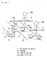
- Fig. 1 is an explanatory view of working stages in a factory and a RFID detection device 1.
- a conveyor belt 21 is placed along working stages A, B, and more stages.
- the conveyor belt 21 is driven by driving means (not shown) and transports articles 27 (27a through 27c) toward each of the working stages.
- a worker Ma performs an operation for the article 27a.
- a worker Mb performs an operation for the article 27b.
- the articles 27 have respective RFID tags 25 (25a through 25c) attached thereto.
- Each of the RFID tags 25 includes an antenna and an IC.
- the IC of the RFID tag 25 has a storage section that stores proper information such as an ID, which is identification information, and a name and specification of the article, which are information on the article.
- the RFID detection device 1 In the working stage B, the RFID detection device 1 is placed which can read the RFID tag 25 existing within a detection area R.
- the RFID detection device 1 includes an antenna 10, a control section 13, and a storage section 15.
- the antenna 10 includes a three-element array antenna which can adjust its directional orientations in a range from 35° to -35°.
- the control section 13 includes a CPU, a ROM, and a RAM, and performs control operations and computations according to a program such as an RFID tag communication program.
- the storage section 15 includes a storage device such as a nonvolatile memory or a hard disk, and stores a program and information (data).
- the present embodiment exemplifies that only the RFID tag 25 in a narrow area extending at angles from -15° to +15° from a front side of the antenna 10 is read, using the RFID detection device 1 as a pseudo-pencil beam antenna.
- Fig. 2 is a graph showing a directional pattern of the antenna 10.
- a longitudinal axis indicates a directional gain (Gain) of the antenna 10 in units of decibel (dBi).
- a lateral axis indicates an angle in units of degree (deg).
- a leftward directional gain D_L ( ⁇ ) plotted in Fig. 2 indicates directional gains in given directions where the front side of the antenna 10 is 0°, when the directional orientation (angle ⁇ ) of the antenna 10 is set to -35°.
- a centerward directional gain D_C ( ⁇ ) plotted in Fig. 2 indicates directional gains in given directions where the front side of the antenna 10 is 0°, when the directional orientation (angle ⁇ ) of the antenna 10 is set to 0°.
- a rightward directional gain D_R ( ⁇ ) plotted in Fig. 2 indicates directional gains in given directions where the front side of the antenna 10 is 0°, when the directional orientation (angle ⁇ ) of the antenna 10 is set to 35°.
- a reception level Rx_L can be expressed by the following equation (Equation 3).
- Equation 3 relational equations in logarithmic form and antilogarithmic form are expressed by the following equations (Equations 1 and 2).
- Pt is a transmission power of the tag
- Loss is a free space loss
- Dt( ⁇ ) is a directional gain of the tag
- D_L( ⁇ ) is a leftward directional gain
- B Rx_L in antilogarithmic form Rx_L ⁇ Pt ⁇ ⁇ Dt ⁇ ⁇ ⁇ ⁇ / 4 ⁇ ⁇ D 2 ⁇ D_L ⁇ ⁇
- Pt' is a transmission power of the tag
- D is a communication distance
- Dt'( ⁇ ) is a directional gain of
- D_L'( ⁇ ) is a leftward directional gain.
- a reception level Rx_R can be expressed by the following equation: Equation 4
- a Rx_R in logarithmic form Rx_R Pt + Dt ⁇ - Loss + D_R ⁇ where Pt is a transmission power of the tag, Loss is a free space loss, Dt( ⁇ ) is a directional gain of the tag, and D_R( ⁇ ) is a rightward directional gain, or
- B Rx_R in antilogarithmic form Rx_R ⁇ Pt ⁇ ⁇ Dt ⁇ ⁇ ⁇ ⁇ / 4 ⁇ ⁇ D 2 ⁇ D_R ⁇ ⁇ where Pt' is a transmission power of the tag, D is a communication distance, Dt'( ⁇ ) is a directional gain of the tag, and D_R'( ⁇ ) is a rightward directional gain.
- reception level ratio (subtraction (difference) for the logarithmic form and division for the antilogarithmic form) is performed to determine a reception level ratio Rx_DIF.
- Equation 5 by performing subtraction or division with respect to the equations for reception levels in different directional orientations, a function having only ⁇ irrelevant to distances and performance of the tag (reflected power and directional gains of the tag) is obtained.
- a longitudinal axis indicates the reception level ratio Rx_DIF (Gain) in units of decibel (dB).
- a lateral axis indicates an angle in units of degree (deg).
- the reception level ratio Rx_DIF is expressed in a graph form that appears to be a linear function at about 0°, which is near the front side of the antenna 10. Note that the reception level ratio Rx_DIF at angles outside about ⁇ 10° is not expressed as a linear function because of a side lobe effect.
- control section 13 in the RFID detection device 1 performs according to an RFID tag communication program to select only the RFID tag 25 in a target area and communicate with the selected RFID tag 25 on the basis of the foregoing theory, with reference to the flowchart shown in Fig. 4 .
- the control section 13 requests the antenna 10 to transmit a signal with its directional orientation set to 35° (step S1).
- the signal transmitted at this time is a signal to make the RFID tag 25 transmit the ID, which is the identification information for the RFID tag 25, in response to the request.
- the control section 13 receives a response signal from the RFID tag 25 through the antenna 10 and then stores the received ID and the reception level Rx_R in the storage section 15 (step S2). At this time, the storage section 15 stores the ID and a rightward directional reception level, as shown in Fig. 5 , which is an explanatory view of reception information stored in the storage section 15.
- the control section 13 requests the antenna 10 to transmit a signal with its directional orientation set to -35° (step S3).
- the signal transmitted at this time is a signal for making the RFID tag 25 transmit the ID, which is the identification information for the RFID tag 25, in response to the request.
- the control section 13 receives a response signal from the RFID tag 25 through the antenna 10 and then stores the received ID and the reception level Rx_L in the storage section 15 (step S4). At this time, as shown in Fig. 5 , the storage section 15 additionally stores a leftward directional reception level as information associated with the ID.
- the control section 13 performs difference operation (subtraction for the logarithmic form and division for the antilogarithmic form) using the reception levels Rx_L and Rx_R for each ID to find the reception level ratio Rx_DIF, and then stores the reception level ratio Rx_DIF as information associated with the ID, as indicated in Fig. 5 (step S5).
- the control section 13 extracts an ID having the reception level ratio Rx_DIF that falls in a range from predetermined thresholds A1 to A2 (in a range from -A1 to A2), and then evaluates only the extracted ID as a valid ID (step S6). This completes the operation.
- the RFID detection device 1 can select and read the RFID tag 25 within a target area narrower than a coverage area where the antenna 10 can intrinsically read the RFID tag 25.
- the coverage area of the antenna 10 is originally vague.
- (D) of Fig. 6 shows a threshold range obtained by synthesis of (B) of Fig. 6 where the directional orientation is shifted by 35° rightward and (C) of Fig. 6 where the directional orientation is shifted by -35° leftward by means of the foregoing method.
- the coverage area target area for reading
- the coverage area is determined within a desired area (in (D) of Fig. 6 , an area extending at angles from +15° to -15°)
- the boundary between the coverage area and a non-coverage area is very clear. Therefore, in the RFID detection device 1, the antenna 10 can be used in the same manner as a high-accuracy pencil beam antenna, which enables reading of only the RFID tag 25 in the desired area.
- the desired area can be adjusted easily with only changes of the thresholds A1 and A2.
- the RFID detection device 1 performs difference operation for the logarithmic form and division for the antilogarithmic form, which enables cancellation of an error caused by distance and performance of the tag (reflected power and directional gain of the tag) and highly-accurate detection.
- the RFID detection device 1 performs reading in leftward and rightward directional orientations (in left and right directions) with a target direction set to be centerward. This makes it possible to reliably read the RFID tag 25 which exists in the target direction.
- Example 2 the RFID detection device 1 in Embodiment 2 is described.
- hardware in the RFID detection device 1 is the same as in Example 1, but only the program-based software processing in Example 2 is different from that in Example 1. Accordingly, only the different processing is described, and the other detailed description is omitted because it is the same as in Example 1.
- Rx_DIF_L leftward reception level ratio
- Rx_DIF_L rightward reception level ratio
- Equation 8 A Rx_DIF_L in logarithmic form
- Rx_DIF_R rightward reception level ratio
- Rx_DIF_R rightward reception level ratio
- the leftward reception level ratio Rx_DIF_L and the rightward reception level ratio Rx_DIF_R are plotted in a graph form in Fig. 7 . Therefore, if the RFID tag 25 which satisfies a condition is selected, an angle range (area) is limited, which enables extraction of the RFID tag 25 in the desired area.
- the thresholds A1 and A2 are identical.
- the condition is expressed by the following equation: Rx_DIF_L > A ⁇ 1 AND Rx_DIF_R > A ⁇ 2 where A1 and A2 are thresholds.
- the present embodiment is described in units of mW or dBm. However, this is not the only possibility. The same result can be obtained even if dBW is used as the unit. Similarly, even with a conversion factor calculated with respect to an isotropic antenna using dBi as the unit as described in the present embodiment, or even with a conversion factor calculated with respect to a dipole antenna using dBd as the unit, which is different from the unit used in the present embodiment, the same result can be obtained.
- control section 13 in the RFID detection device 1 performs according to an RFID tag communication program to select only the RFID tag 25 in a target area and communicate with the selected RFID tag 25 on the basis of the foregoing theory, with reference to the flowchart shown in Fig. 8 .
- the control section 13 requests the antenna 10 to transmit a signal with its directional orientation set to 35° (step S11).
- the signal transmitted at this time is a signal for making the RFID tag 25 transmit the ID, which is the identification information for the RFID tag 25, in response to the request.
- the control section 13 receives a response signal from the RFID tag 25 through the antenna 10, and then stores the received ID and the reception level Rx_R in the storage section 15 (step S12).
- the control section 13 requests the antenna 10 to transmit a signal with its directional orientation set to 0° (step S13).
- the signal transmitted at this time is a signal for making the RFID tag 25 transmit the ID, which is the identification information for the RFID tag 25, in response to the request.
- the control section 13 receives a response signal from the RFID tag 25 through the antenna 10, and then stores the received ID and the reception level Rx_C in the storage section 15 (step S14).
- the control section 13 requests the antenna 10 to transmit a signal with its direction orientation set to -35° (step S15).
- the signal transmitted at this time is a signal for making the RFID tag 25 transmit the ID, which is the identification information for the RFID tag 25, in response to the request,
- the control section 13 receives a response signal from the RFID tag 25 through the antenna 10, and then stores the received ID and the reception level Rx_L in the storage section 15 (step S16).
- the control section 13 performs difference operation or division using the reception levels Rx_R and Rx_C for each ID to find the rightward reception level ratio Rx_DIF_R (step S 17).
- the control section 13 performs difference operation or division using the reception levels Rx_L and Rx_C for each ID to find the leftward reception level ratio Rx_DIF_L (step S18).
- the control section 13 performs difference operation or division using the rightward reception level ratio Rx_DIF_R and the leftward reception level ratio Rx_DIF_L for each ID to find the reception level ratio Rx_DIF (step S19).
- the control section 13 extracts an ID having the reception level ratio Rx_DIF that falls in a range from predetermined thresholds A1 to A2 (in a range where the Rx_DIF_R is larger than A1 and the Rx_DIF_L is larger than A2), and then evaluates only the extracted ID as a valid ID (step S20). This completes the operation.
- Example 2 With the above configuration and operations, the same result as in Example 1 can be obtained, and the RFID tag 25 in the target area (within an area extending at target angles) can be detected.
- Example 2 since the centerward reception level Rx_C is used, a length of the coverage area in the centerward direction, which is the target area, can be made adequately longer than the range in Example 1. That is, in Example 1, the centerward reception level Rx_C is not used. Therefore, the length of the coverage area in the centerward direction, which is the target area, decreases with increase of the difference in directional orientation angle between the reception level Rx_L and the reception level Rx_R.
- Example 2 the centerward reception level Rx_C is used. Therefore, the length of the coverage area in the centerward direction, which is the target area, does not decrease, and the coverage area with a long length and in a narrow width can be arranged.
- steps S4, n14 and n16 which are the steps of performing reading after the directional orientation is shifted information associated with the ID may be discarded without being stored.
- the information may be stored independently, and only if the presence of the same ID is confirmed in both of the steps (those three steps in Embodiment 2), the information corresponding to the ID may be extracted and subjected to operation. This makes it possible to easily eliminate the RFID tag 25 which has been received only in one of the directional orientations from target tags to be detected.
- a non-contact IC medium communication device of the present invention corresponds to the RFID detection device 1 in the embodiment. Similarly, the following will describe correspondences between components in the present invention and components in the foregoing embodiments:
Abstract
Description
- The present invention relates to a non-contact IC medium communication device, for example, which detects a non-contact IC medium within a desired area, a method thereof, a program thereof, and a computer-readable storage medium storing the program.
- Non-contact IC media capable of performing communication of information stored therein in a noncontact manner are conventionally utilized. Such non-contact IC media include a medium using a UHF band available for long-distance communication. In most cases, a single-element patch antenna is often used as an antenna for communicating with the non-contact IC medium using the UHF band. The single-element patch antenna has a half-power width (beamwidth) as broad as about 70 and therefore has the advantage of reading information from the non-contact IC media in a broad area.
- However, in some cases, only the non-contact IC medium within a specific area need to be read. Particularly, such cases include, for example, a case that, under the situation where articles are transported while undergoing a plurality of working stages, only the non-contact IC medium of the article in one working operation need to be read.
- In this case, it is considered to use an antenna with a narrow half-power width. However, such an antenna needs to be extremely large in size, like a multiple-element array antenna and a parabola antenna.
- Meanwhile, there has been proposed a tag communication device that calculates the position of a non-contact IC medium on the basis of estimated incoming direction of a radio wave from the non-contact IC medium (see Patent Literature 1). The tag communication device applies different weights to outputs of antenna elements to detect the intensity of the radio wave in a specific direction.
- However, the tag communication device requires complicated calculations in order to find the direction where the one non-contact IC medium exists.
-
Patent Literature 1
Japanese Patent Application Publication,Tokukai, No. 2006-10345 A (Publication Date: January 12, 2006 - The present invention has been made in view of the foregoing problems, and an object of the present invention is to provide a non-contact IC medium communication device capable of detecting, with a simple configuration, a non-contact IC medium in a desired area, a method thereof, a program thereof and a computer-readable storage medium storing the program.
- The present invention is characterized by a non-contact IC medium communication device comprising: receiving means for obtaining, from each of separate read areas, identification information of a non-contact IC medium that exists within the read area and a signal level of a reception signal received from the non-contact IC medium, the identification information and the signal level being associated with each other; operating means for performing difference operation or division with respect to respective signal levels of reception signals from the separate read areas, for each of the identification information, to obtain a composite signal level; and extracting means for extracting the identification information whose composite signal level falls within a predetermined threshold range, a method thereof, and a program thereof.
- The separate read areas differ from each other in their coverage areas, and read directions of an antenna having directivity in the separate read areas differ from each other.
- The non-contact IC medium is a medium, such as an RF-ID tag, which can store information and perform communication in a noncontact manner. The non-contact IC medium includes a passive type medium which is not provided with a power source and obtains induced electromotive force from an external entity to transmit a response signal, a semi-passive type medium which is provided with a power source and transmits the response signal in response to a request from an external entity, and an active type medium which is provided with a power source and transmits signals at regular intervals.
- The identification information is information by which the non-contact IC medium can be identified, such as an ID of an RF-ID tag.
- A signal received from the non-contact IC medium is a response signal for the non-contact IC medium transmitting the identification information or another signal transmitted by the non-contact IC medium.
- The receiving means can be realized by one or more array antennas whose directional patterns can be changed or by a plurality of antennas whose directional pattern cannot be changed.
- The operating means and extracting means can be realized by means for performing an operation, such as CPU or MPU.
- The non-contact IC medium communication device can be a reader/writer device which transmits/ receives information to/from the non-contact IC medium or a reader device which reads information from the non-contact IC medium. Furthermore, the non-contact IC medium communication device also includes a device used as a detection device for detecting the non-contact IC medium.
- Note that the non-contact IC medium communication device may be realized by a computer. In this case, the present invention also includes a non-contact IC medium communication program of the non-contact IC medium communication device which realizes the non-contact IC medium communication device by causing the computer to operate as each of the means, and a computer-readable storage medium storing the program.
- The present invention can provide a non-contact IC medium communication device capable of detecting a non-contact IC medium in a desired area with a simple configuration, a method thereof, a program thereof, and a computer-readable storage medium storing the program.
-
-
Fig. 1
Fig. 1 is an explanatory view of working stages in a factory and a RFID detection device. -
Fig. 2
Fig. 2 is a graph showing respective reception levels in different directional orientations. -
Fig. 3
Fig. 3 is a graph of a reception level ratio. -
Fig. 4
Fig. 4 is a flowchart of operations performed by a control section. -
Fig. 5
Fig. 5 is an explanatory view of reception information stored in a storage section. -
Fig. 6
Fig. 6 is an explanatory view of a coverage area of an antenna. -
Fig. 7
Fig. 7 is a graph of leftward and rightward reception ratios in Example 2. -
Fig.8
Fig. 8 is a flowchart of operations performed by a control section in Example 2. - 1...RFID DETECTION DEVICE, 10...ANTENNA, 13...CONTROL SECTION, 25...RFID TAG, A1 and A2...THRESHOLD, R2...NORMAL AREA, Rx_L and Rx_R...RECEPTION LEVEL, Rx_DIF...RECEPTION LEVEL RATIO, Rx_DIF_L...LEFTWARD RECEPTION LEVEL RATIO, Rx_DIF_R...RIGHTWARD RECEPTION LEVEL RATIO
- The following will describe an embodiment of the present invention with reference to the drawings.
-
Fig. 1 is an explanatory view of working stages in a factory and aRFID detection device 1. - In a factory, a
conveyor belt 21 is placed along working stages A, B, and more stages. Theconveyor belt 21 is driven by driving means (not shown) and transports articles 27 (27a through 27c) toward each of the working stages. - In the working stage A, a worker Ma performs an operation for the
article 27a. In the working stage B, a worker Mb performs an operation for thearticle 27b. - The articles 27 have respective RFID tags 25 (25a through 25c) attached thereto. Each of the
RFID tags 25 includes an antenna and an IC. The IC of theRFID tag 25 has a storage section that stores proper information such as an ID, which is identification information, and a name and specification of the article, which are information on the article. - In the working stage B, the
RFID detection device 1 is placed which can read theRFID tag 25 existing within a detection area R. TheRFID detection device 1 includes anantenna 10, a control section 13, and astorage section 15. - The
antenna 10 includes a three-element array antenna which can adjust its directional orientations in a range from 35° to -35°. - The control section 13 includes a CPU, a ROM, and a RAM, and performs control operations and computations according to a program such as an RFID tag communication program.
- The
storage section 15 includes a storage device such as a nonvolatile memory or a hard disk, and stores a program and information (data). - Next, the following will describe the theory of a method for reading only the
RFID tag 25 in a desired area with use of the RFID detection device. The present embodiment exemplifies that only theRFID tag 25 in a narrow area extending at angles from -15° to +15° from a front side of theantenna 10 is read, using theRFID detection device 1 as a pseudo-pencil beam antenna. -
Fig. 2 is a graph showing a directional pattern of theantenna 10. In the graph, a longitudinal axis indicates a directional gain (Gain) of theantenna 10 in units of decibel (dBi). A lateral axis indicates an angle in units of degree (deg). - A leftward directional gain D_L (θ) plotted in
Fig. 2 indicates directional gains in given directions where the front side of theantenna 10 is 0°, when the directional orientation (angle θ) of theantenna 10 is set to -35°. - A centerward directional gain D_C (θ) plotted in
Fig. 2 indicates directional gains in given directions where the front side of theantenna 10 is 0°, when the directional orientation (angle θ) of theantenna 10 is set to 0°. - A rightward directional gain D_R (θ) plotted in
Fig. 2 indicates directional gains in given directions where the front side of theantenna 10 is 0°, when the directional orientation (angle θ) of theantenna 10 is set to 35°. - Here, a reception level Rx_L can be expressed by the following equation (Equation 3). Note that relational equations in logarithmic form and antilogarithmic form are expressed by the following equations (
Equations 1 and 2). (Equation 1)

where Rx (dBm) is expressed in logarithmic form, and Rx' (mW) is expressed in antilogarithmic form.
where Pt is a transmission power of the tag, Loss is a free space loss, Dt(θ) is a directional gain of the tag, and D_L(θ) is a leftward directional gain, or
where Pt' is a transmission power of the tag, D is a communication distance, Dt'(θ) is a directional gain of - the tag, and D_L'(θ) is a leftward directional gain.
- Further, a reception level Rx_R can be expressed by the following equation:

where Pt is a transmission power of the tag, Loss is a free space loss, Dt(θ) is a directional gain of the tag, and D_R(θ) is a rightward directional gain, or
where Pt' is a transmission power of the tag, D is a communication distance, Dt'(θ) is a directional gain of the tag, and D_R'(θ) is a rightward directional gain. - Regarding the foregoing two equations, an operation for a reception level ratio (subtraction (difference) for the logarithmic form and division for the antilogarithmic form) is performed to determine a reception level ratio Rx_DIF. The reception level ratio Rx_DIF is expressed by the following equation:


- As expressed in
Equation 5, by performing subtraction or division with respect to the equations for reception levels in different directional orientations, a function having only θ irrelevant to distances and performance of the tag (reflected power and directional gains of the tag) is obtained. - This function is shown in graph form in
Fig. 3 . In the graph, a longitudinal axis indicates the reception level ratio Rx_DIF (Gain) in units of decibel (dB). A lateral axis indicates an angle in units of degree (deg). - As shown in the graph, the reception level ratio Rx_DIF is expressed in a graph form that appears to be a linear function at about 0°, which is near the front side of the
antenna 10. Note that the reception level ratio Rx_DIF at angles outside about ±10° is not expressed as a linear function because of a side lobe effect. - Therefore, only the
RFID tag 25 whose reception level ratio Rx_DIF satisfies a condition is extracted with use of thresholds A1 and A2, which enables selection of only theRFID tag 25 that exists on the front side of theantenna 10. That is, except for thetarget RFID tag 25, the other RFID tags 25 can be eliminated even if they are read. The condition is expressed by the following equation:
where A1 is a lower threshold and A2 is an upper threshold. - Next, the following will describe operations that the control section 13 in the
RFID detection device 1 performs according to an RFID tag communication program to select only theRFID tag 25 in a target area and communicate with the selectedRFID tag 25 on the basis of the foregoing theory, with reference to the flowchart shown inFig. 4 . - The control section 13 requests the
antenna 10 to transmit a signal with its directional orientation set to 35° (step S1). The signal transmitted at this time is a signal to make theRFID tag 25 transmit the ID, which is the identification information for theRFID tag 25, in response to the request. - The control section 13 receives a response signal from the
RFID tag 25 through theantenna 10 and then stores the received ID and the reception level Rx_R in the storage section 15 (step S2). At this time, thestorage section 15 stores the ID and a rightward directional reception level, as shown inFig. 5 , which is an explanatory view of reception information stored in thestorage section 15. - The control section 13 requests the
antenna 10 to transmit a signal with its directional orientation set to -35° (step S3). As in the step S1, the signal transmitted at this time is a signal for making theRFID tag 25 transmit the ID, which is the identification information for theRFID tag 25, in response to the request. - The control section 13 receives a response signal from the
RFID tag 25 through theantenna 10 and then stores the received ID and the reception level Rx_L in the storage section 15 (step S4). At this time, as shown inFig. 5 , thestorage section 15 additionally stores a leftward directional reception level as information associated with the ID. - The control section 13 performs difference operation (subtraction for the logarithmic form and division for the antilogarithmic form) using the reception levels Rx_L and Rx_R for each ID to find the reception level ratio Rx_DIF, and then stores the reception level ratio Rx_DIF as information associated with the ID, as indicated in
Fig. 5 (step S5). - The control section 13 extracts an ID having the reception level ratio Rx_DIF that falls in a range from predetermined thresholds A1 to A2 (in a range from -A1 to A2), and then evaluates only the extracted ID as a valid ID (step S6). This completes the operation.
- With the above configuration and operations, the
RFID detection device 1 can select and read theRFID tag 25 within a target area narrower than a coverage area where theantenna 10 can intrinsically read theRFID tag 25. - More specifically, as shown in (A) through (C) in
Fig. 6 , the coverage area of theantenna 10 is originally vague. - That is, when the directional orientation is 0° in (A) of
Fig. 6 , no clear boundaries exist between a strong area R1 where theantenna 10 can receive a signal with high strength and a normal area R2 where theantenna 10 can receive a signal to some extent and between the normal area R2 and its surrounding area, and the all of these areas are smoothly continuous. Therefore, in one case theantenna 10 can read theRFID tag 25, and in another case theantenna 10 cannot read theRFID tag 25. This occurs depending on a surrounding environment of theantenna 10. Moreover, due to the presence of a side lobe area R3, it is difficult to determine a clear coverage area of theantenna 10 from one received result. - Similarly, in both cases of (B) of
Fig. 6 where the directional orientation is shifted by 35° rightward and (C) ofFig. 6 where the directional orientation is shifted by -35° leftward, the coverage area of theantenna 10 is vague without boundaries. - On the contrary, (D) of
Fig. 6 shows a threshold range obtained by synthesis of (B) ofFig. 6 where the directional orientation is shifted by 35° rightward and (C) ofFig. 6 where the directional orientation is shifted by -35° leftward by means of the foregoing method. In (D) ofFig. 6 , the coverage area (target area for reading) is determined within a desired area (in (D) ofFig. 6 , an area extending at angles from +15° to -15°), and the boundary between the coverage area and a non-coverage area is very clear. Therefore, in theRFID detection device 1, theantenna 10 can be used in the same manner as a high-accuracy pencil beam antenna, which enables reading of only theRFID tag 25 in the desired area. - Further, in the
RFID detection device 1, the desired area can be adjusted easily with only changes of the thresholds A1 and A2. - Moreover, the
RFID detection device 1 performs difference operation for the logarithmic form and division for the antilogarithmic form, which enables cancellation of an error caused by distance and performance of the tag (reflected power and directional gain of the tag) and highly-accurate detection. - Furthermore, the
RFID detection device 1 performs reading in leftward and rightward directional orientations (in left and right directions) with a target direction set to be centerward. This makes it possible to reliably read theRFID tag 25 which exists in the target direction. - Next, the
RFID detection device 1 inEmbodiment 2 is described. In this case, hardware in theRFID detection device 1 is the same as in Example 1, but only the program-based software processing in Example 2 is different from that in Example 1. Accordingly, only the different processing is described, and the other detailed description is omitted because it is the same as in Example 1. - The reception level Rx_C described in Example 1 is expressed by the following equation:


where Pt' is a transmission power of the tag, D is a communication distance, Dt'(θ) is a directional gain of the tag, and D_C'(θ) is a centerward directional gain. - Then, subtraction (subtraction in logarithmic form, and division in antilogarithmic form) is performed using the reception levels Rx_L and Rx_C described in Example 1 to find a leftward reception level ratio Rx_DIF_L. The leftward reception level ratio Rx_DIF_L is expressed by the following equation:

Further, subtraction (subtraction for the logarithmic form and division for the antilogarithmic form) is performed using the reception levels Rx_R and Rx_C described in Example 1 to find a rightward reception level ratio Rx_DIF_R. The rightward reception level ratio Rx_DIF_R is expressed by the following equation:
- The leftward reception level ratio Rx_DIF_L and the rightward reception level ratio Rx_DIF_R are plotted in a graph form in
Fig. 7 . Therefore, if theRFID tag 25 which satisfies a condition is selected, an angle range (area) is limited, which enables extraction of theRFID tag 25 in the desired area. Note that in the example ofFig. 7 , the thresholds A1 and A2 are identical. The condition is expressed by the following equation:
where A1 and A2 are thresholds. - Note that a remainder (or a quotient) from the directional gains is conclusively required by the equations described in the present embodiment, and the remainder (or the quotient) is obtained as a ratio. Therefore, the present embodiment is described in units of mW or dBm. However, this is not the only possibility. The same result can be obtained even if dBW is used as the unit. Similarly, even with a conversion factor calculated with respect to an isotropic antenna using dBi as the unit as described in the present embodiment, or even with a conversion factor calculated with respect to a dipole antenna using dBd as the unit, which is different from the unit used in the present embodiment, the same result can be obtained.
- Next, the following will describe operations that the control section 13 in the
RFID detection device 1 performs according to an RFID tag communication program to select only theRFID tag 25 in a target area and communicate with the selectedRFID tag 25 on the basis of the foregoing theory, with reference to the flowchart shown inFig. 8 . - The control section 13 requests the
antenna 10 to transmit a signal with its directional orientation set to 35° (step S11). The signal transmitted at this time is a signal for making theRFID tag 25 transmit the ID, which is the identification information for theRFID tag 25, in response to the request. - The control section 13 receives a response signal from the
RFID tag 25 through theantenna 10, and then stores the received ID and the reception level Rx_R in the storage section 15 (step S12). - The control section 13 requests the
antenna 10 to transmit a signal with its directional orientation set to 0° (step S13). As in the step S1, the signal transmitted at this time is a signal for making theRFID tag 25 transmit the ID, which is the identification information for theRFID tag 25, in response to the request. - The control section 13 receives a response signal from the
RFID tag 25 through theantenna 10, and then stores the received ID and the reception level Rx_C in the storage section 15 (step S14). - The control section 13 requests the
antenna 10 to transmit a signal with its direction orientation set to -35° (step S15). As in the step S1, the signal transmitted at this time is a signal for making theRFID tag 25 transmit the ID, which is the identification information for theRFID tag 25, in response to the request, - The control section 13 receives a response signal from the
RFID tag 25 through theantenna 10, and then stores the received ID and the reception level Rx_L in the storage section 15 (step S16). - The control section 13 performs difference operation or division using the reception levels Rx_R and Rx_C for each ID to find the rightward reception level ratio Rx_DIF_R (step S 17).
- The control section 13 performs difference operation or division using the reception levels Rx_L and Rx_C for each ID to find the leftward reception level ratio Rx_DIF_L (step S18).
- The control section 13 performs difference operation or division using the rightward reception level ratio Rx_DIF_R and the leftward reception level ratio Rx_DIF_L for each ID to find the reception level ratio Rx_DIF (step S19).
- The control section 13 extracts an ID having the reception level ratio Rx_DIF that falls in a range from predetermined thresholds A1 to A2 (in a range where the Rx_DIF_R is larger than A1 and the Rx_DIF_L is larger than A2), and then evaluates only the extracted ID as a valid ID (step S20). This completes the operation.
- With the above configuration and operations, the same result as in Example 1 can be obtained, and the
RFID tag 25 in the target area (within an area extending at target angles) can be detected. - Particularly, in the Example 2, since the centerward reception level Rx_C is used, a length of the coverage area in the centerward direction, which is the target area, can be made adequately longer than the range in Example 1. That is, in Example 1, the centerward reception level Rx_C is not used. Therefore, the length of the coverage area in the centerward direction, which is the target area, decreases with increase of the difference in directional orientation angle between the reception level Rx_L and the reception level Rx_R.
- On the contrary, in Example 2, the centerward reception level Rx_C is used. Therefore, the length of the coverage area in the centerward direction, which is the target area, does not decrease, and the coverage area with a long length and in a narrow width can be arranged.
- This makes it possible to make the
conveyor belt 21 separated well away from theantenna 10, which enables an easier design for a series of working stages than in Example 1. - Note that in each of the foregoing embodiments, if the absence of an ID is confirmed corresponding to an ID which has been read in a first directional orientation in steps S4, n14 and n16 which are the steps of performing reading after the directional orientation is shifted, information associated with the ID may be discarded without being stored. Furthermore, in the steps S2 and S4 (the steps S12, n14, and n16 in Embodiment 2), the information may be stored independently, and only if the presence of the same ID is confirmed in both of the steps (those three steps in Embodiment 2), the information corresponding to the ID may be extracted and subjected to operation. This makes it possible to easily eliminate the
RFID tag 25 which has been received only in one of the directional orientations from target tags to be detected. - A non-contact IC medium communication device of the present invention corresponds to the
RFID detection device 1 in the embodiment. Similarly, the following will describe correspondences between components in the present invention and components in the foregoing embodiments: - receiving means corresponds to the
antenna 10; - operating means corresponds to the control section 13 which executes step S5;
- extractiing means corresponds to the control section 13 which executes step S6;
- a non-contact IC medium corresponds to the
RFID tag 25; - a threshold range corresponds to a range from threshold -A1 to threshold A2;
- separate read areas correspond to normal areas R2;
- signal levels corresponds to reception levels Rx_L and Rx_R;
- a composite signal level corresponds to a reception level ratio Rx_DIF;
- a first composite level corresponds to a leftward reception level ratio Rx_DIF_L;
- a second composite level corresponds to a rightward reception level ratio Rx_DIF_R;
- a receiving process corresponds to steps S2, S4, S12, S14, and S16;
- an operating process corresponds to steps S5 and S19;
- an extracting process corresponds to steps S6 and S20;
- a non-contact IC medium communication program corresponds to the RFID tag communication program;
- identification information corresponds to the ID; and
- a signal received from the non-contact IC medium corresponds to a response signal from the
RFID tag 25. However, the present invention is not limited to the configurations of the foregoing embodiments, and many embodiments can be obtained.
Claims (6)
- A non-contact IC medium communication device comprising:receiving means for obtaining, from each of separate read areas, identification information of a non-contact IC medium that exists within the read area and a signal level of a reception signal received from the non-contact IC medium, the identification information and the signal level being associated with each other;operating means for performing difference operation or division with respect to respective signal levels of reception signals from the separate read areas, for each of the identification information, to obtain a composite signal level; andextracting means for extracting the identification information whose composite signal level falls within a predetermined threshold range.
- The non-contact IC medium communication device as set forth in claim 1, wherein
the read areas are provided at least on both sides of a target area for reading. - The non-contact IC medium communication device as set forth in claim 2, wherein
the read area is further provided in a center area which has the target area at a center thereof, and
the operating means performs difference operation or division with respect to the signal level of the reception signal in one of the read areas on the both sides of the target area and the signal level of the reception signal in the center area to obtain a first composite signal level,
performs difference operation or division with respect to the signal level of the reception signal in the other of the read areas on the both sides of the target area and the signal level of the reception signal in the center area to obtain a second composite signal level, and
performs difference operation or division with respect to the first and second composite signal levels to obtain a composite signal level. - A method of non-contact IC medium communication, comprising the steps of:obtaining, from each of separate read areas, identification information of a non-contact IC medium that exists within the read area and a signal level of a reception signal received from the non-contact IC medium, the identification information and the signal level being associated with each other;performing difference operation or division with respect to respective signal levels of reception signals from the separate read areas, for each of the identification information, to obtain a composite signal level; andextracting the identification information whose composite signal level falls within a predetermined threshold range.
- A non-contact IC medium communication program performing:a receiving process of obtaining, from each of separate read areas, identification information of a non-contact IC medium that exists within the read area and a signal level of a reception signal received from the non-contact IC medium, the identification information and the signal level being associated with each other;an operating process of performing difference operation or division with respect to respective signal levels of reception signals from the separate read areas, for each of the identification information, to obtain a composite signal level; andan extracting process of extracting the identification information whose composite signal level falls within a predetermined threshold range.
- A computer-readable storage medium storing a non-contact IC medium communication program for causing a computer to perform:a receiving process of obtaining, from each of separate read areas, identification information of a non-contact IC medium that exists within the read area and a signal level of a reception signal received from the non-contact IC medium, the identification information and the signal level being associated with each other;an operating process of performing difference operation or division with respect to respective signal levels of reception signals from the separate read areas, for each of the identification information, to obtain a composite signal level; andan extracting process of extracting the identification information whose composite signal level falls within a predetermined threshold range.
Applications Claiming Priority (3)
| Application Number | Priority Date | Filing Date | Title |
|---|---|---|---|
| JP2007313431 | 2007-12-04 | ||
| JP2007339851A JP4285576B1 (en) | 2007-12-04 | 2007-12-28 | Non-contact IC medium communication apparatus and method, and program thereof |
| PCT/JP2008/071953 WO2009072518A1 (en) | 2007-12-04 | 2008-12-03 | Non-contact ic medium communication device |
Publications (3)
| Publication Number | Publication Date |
|---|---|
| EP2228755A1 true EP2228755A1 (en) | 2010-09-15 |
| EP2228755A4 EP2228755A4 (en) | 2011-09-14 |
| EP2228755B1 EP2228755B1 (en) | 2013-11-27 |
Family
ID=40717697
Family Applications (1)
| Application Number | Title | Priority Date | Filing Date |
|---|---|---|---|
| EP08856767.2A Active EP2228755B1 (en) | 2007-12-04 | 2008-12-03 | Non-contact ic medium communication device |
Country Status (5)
| Country | Link |
|---|---|
| US (1) | US8456281B2 (en) |
| EP (1) | EP2228755B1 (en) |
| JP (1) | JP4285576B1 (en) |
| CN (2) | CN101785015A (en) |
| WO (1) | WO2009072518A1 (en) |
Families Citing this family (6)
| Publication number | Priority date | Publication date | Assignee | Title |
|---|---|---|---|---|
| JP5271132B2 (en) * | 2009-03-25 | 2013-08-21 | 日立マクセル株式会社 | Workpiece with direction discrimination function |
| JP4998528B2 (en) * | 2009-09-15 | 2012-08-15 | 三菱電機株式会社 | RFID reader / writer device and process management system |
| DE102016213240A1 (en) | 2016-02-12 | 2017-08-17 | Fraunhofer-Gesellschaft zur Förderung der angewandten Forschung e.V. | Device and method for determining the position of a transmitter relative to a detection area |
| JP6410745B2 (en) * | 2016-02-24 | 2018-10-24 | 三菱電機株式会社 | Angle measuring device |
| JP6682994B2 (en) * | 2016-04-28 | 2020-04-15 | オムロン株式会社 | Communication device, system and program including communication device |
| JP7010256B2 (en) * | 2019-03-14 | 2022-01-26 | オムロン株式会社 | Information processing device, reader / writer, sidelobe passage determination method, control program |
Citations (2)
| Publication number | Priority date | Publication date | Assignee | Title |
|---|---|---|---|---|
| EP0715185A2 (en) * | 1994-11-30 | 1996-06-05 | Hughes Aircraft Company | Transponder detection system and method |
| EP1610258A1 (en) * | 2004-06-22 | 2005-12-28 | Omron Corporation | RFID communication apparatus with tag position detection means |
Family Cites Families (19)
| Publication number | Priority date | Publication date | Assignee | Title |
|---|---|---|---|---|
| JPH0962816A (en) * | 1994-10-06 | 1997-03-07 | Mitsubishi Electric Corp | Non-contact ic card and non-contact ic card system including the same |
| US6107910A (en) * | 1996-11-29 | 2000-08-22 | X-Cyte, Inc. | Dual mode transmitter/receiver and decoder for RF transponder tags |
| US6289209B1 (en) * | 1996-12-18 | 2001-09-11 | Micron Technology, Inc. | Wireless communication system, radio frequency communications system, wireless communications method, radio frequency communications method |
| EP1121812A4 (en) * | 1998-09-11 | 2003-04-09 | Key Trak Inc | Object control and tracking system with zonal transition detection |
| JP4166401B2 (en) * | 2000-02-17 | 2008-10-15 | 松下電器産業株式会社 | Reception directivity control method, antenna apparatus, and mobile communication base station and mobile station using the same |
| WO2001095240A2 (en) * | 2000-06-05 | 2001-12-13 | Transcore Holdings, Inc. | Method and apparatus to determine the direction to a transponder in a modulated backscatter communication system |
| JP3784327B2 (en) * | 2002-01-18 | 2006-06-07 | 三菱電機株式会社 | Ranging radar equipment |
| KR100402233B1 (en) * | 2002-06-11 | 2003-10-17 | Digitalsis Co Ltd | Apparatus and method for arbitrating communication between transponders having controller and plural mobile objects |
| JP4110998B2 (en) * | 2003-02-21 | 2008-07-02 | ブラザー工業株式会社 | Communication system and interrogator included in communication system |
| GB2453477A (en) * | 2004-02-06 | 2009-04-08 | Zih Corp | Identifying a plurality of transponders |
| KR100682869B1 (en) * | 2004-10-15 | 2007-02-15 | 삼성전기주식회사 | Location tracking system and method |
| US20060197652A1 (en) * | 2005-03-04 | 2006-09-07 | International Business Machines Corporation | Method and system for proximity tracking-based adaptive power control of radio frequency identification (RFID) interrogators |
| JP2007033415A (en) * | 2005-07-29 | 2007-02-08 | Murata Mfg Co Ltd | Radar apparatus |
| JP2007306484A (en) * | 2006-05-15 | 2007-11-22 | Omron Corp | Tag communication system, interference prevention method, and tag communication control device |
| JP2008003007A (en) * | 2006-06-23 | 2008-01-10 | Fujitsu Ltd | Method and device of recognizing individual, method of regulating individual recognition range, and program |
| KR100859093B1 (en) * | 2007-04-30 | 2008-09-17 | 광주과학기술원 | Apparatus and method for navigating using rfid |
| US7884712B2 (en) * | 2007-05-08 | 2011-02-08 | Awarepoint Corporation | Wireless tracking system and method utilizing tags with variable power level transmissions |
| US8451098B2 (en) * | 2007-08-05 | 2013-05-28 | Intel Corporation | Switchable active-passive RFID tag |
| JP4353298B2 (en) * | 2007-12-13 | 2009-10-28 | オムロン株式会社 | Non-contact IC medium direction detection device and method, and program thereof |
-
2007
- 2007-12-28 JP JP2007339851A patent/JP4285576B1/en active Active
-
2008
- 2008-12-03 CN CN200880104226A patent/CN101785015A/en active Pending
- 2008-12-03 EP EP08856767.2A patent/EP2228755B1/en active Active
- 2008-12-03 WO PCT/JP2008/071953 patent/WO2009072518A1/en active Application Filing
- 2008-12-03 US US12/675,371 patent/US8456281B2/en active Active
- 2008-12-03 CN CN201511008774.XA patent/CN105467357B/en active Active
Patent Citations (2)
| Publication number | Priority date | Publication date | Assignee | Title |
|---|---|---|---|---|
| EP0715185A2 (en) * | 1994-11-30 | 1996-06-05 | Hughes Aircraft Company | Transponder detection system and method |
| EP1610258A1 (en) * | 2004-06-22 | 2005-12-28 | Omron Corporation | RFID communication apparatus with tag position detection means |
Non-Patent Citations (1)
| Title |
|---|
| See also references of WO2009072518A1 * |
Also Published As
| Publication number | Publication date |
|---|---|
| US20100245047A1 (en) | 2010-09-30 |
| JP4285576B1 (en) | 2009-06-24 |
| US8456281B2 (en) | 2013-06-04 |
| WO2009072518A1 (en) | 2009-06-11 |
| EP2228755B1 (en) | 2013-11-27 |
| CN101785015A (en) | 2010-07-21 |
| JP2009157892A (en) | 2009-07-16 |
| EP2228755A4 (en) | 2011-09-14 |
| CN105467357B (en) | 2018-12-18 |
| CN105467357A (en) | 2016-04-06 |
Similar Documents
| Publication | Publication Date | Title |
|---|---|---|
| EP2228755B1 (en) | Non-contact ic medium communication device | |
| JP4239033B2 (en) | Interrogator for RFID tag communication system | |
| EP1610258B1 (en) | RFID communication apparatus with tag position detection means | |
| EP2180431A1 (en) | Tag associating system, tag associating method and tag moving direction detection system | |
| Bhattacharyya et al. | RFID tag antenna based temperature sensing in the frequency domain | |
| US9733335B2 (en) | RFID tag locationing using dynamic beacon tag association | |
| US20070273530A1 (en) | Tag communication device, tag moving direction detecting system and tag moving direction detecting method | |
| US20120223811A1 (en) | Multiple Antenna Localizing | |
| EP3898289B1 (en) | Method and system for reading/writing data from/on rfid tags integrated/applied in/on tires conveyed on conveyor belts | |
| EP2233942B1 (en) | Apparatus, method and program for detecting direction of noncontact ic medium and computer-readable recording medium having the program recorded thereon | |
| US11039538B2 (en) | Communication system including antennas on flexible circuit board | |
| US9244162B2 (en) | Method, system and computer program product for ranging RFID tags | |
| WO2020139448A1 (en) | Methods and system for enhanced rfid direction finding | |
| US11693079B2 (en) | Device for determining a position of a transmitter and corresponding method | |
| JP7095325B2 (en) | Wireless tag reader | |
| JP2007304874A (en) | System and device for specifying location of radio ic tag | |
| JP2005345198A (en) | Interrogator for wireless tag communication system and wireless tag communication system | |
| EP3035072A1 (en) | Pseudo-doppler direction finding antenna adaption for RFID applications | |
| US11346915B2 (en) | Device and method for determining the position of a transmitter relative to a detection region | |
| US20080122627A1 (en) | Method and apparatus for reading radio frequency identification tags | |
| JP2005069861A (en) | Radio communication equipment | |
| US11757494B2 (en) | RFID reader with configuration for either an internal antenna or external antenna | |
| JP2020052623A (en) | Wireless tag reader | |
| WO2013169441A1 (en) | Rfid tag reader and method for reading an rfid tag | |
| Ukkonen et al. | Radar cross section modelling of RFID tag antennas for paper reel identification |
Legal Events
| Date | Code | Title | Description |
|---|---|---|---|
| PUAI | Public reference made under article 153(3) epc to a published international application that has entered the european phase |
Free format text: ORIGINAL CODE: 0009012 |
|
| 17P | Request for examination filed |
Effective date: 20100222 |
|
| AK | Designated contracting states |
Kind code of ref document: A1 Designated state(s): AT BE BG CH CY CZ DE DK EE ES FI FR GB GR HR HU IE IS IT LI LT LU LV MC MT NL NO PL PT RO SE SI SK TR |
|
| AX | Request for extension of the european patent |
Extension state: AL BA MK RS |
|
| DAX | Request for extension of the european patent (deleted) | ||
| A4 | Supplementary search report drawn up and despatched |
Effective date: 20110812 |
|
| RIC1 | Information provided on ipc code assigned before grant |
Ipc: H04B 5/02 20060101ALI20110808BHEP Ipc: G01S 3/14 20060101ALI20110808BHEP Ipc: G06K 17/00 20060101AFI20110808BHEP |
|
| 17Q | First examination report despatched |
Effective date: 20120305 |
|
| GRAP | Despatch of communication of intention to grant a patent |
Free format text: ORIGINAL CODE: EPIDOSNIGR1 |
|
| INTG | Intention to grant announced |
Effective date: 20130627 |
|
| GRAS | Grant fee paid |
Free format text: ORIGINAL CODE: EPIDOSNIGR3 |
|
| GRAA | (expected) grant |
Free format text: ORIGINAL CODE: 0009210 |
|
| AK | Designated contracting states |
Kind code of ref document: B1 Designated state(s): AT BE BG CH CY CZ DE DK EE ES FI FR GB GR HR HU IE IS IT LI LT LU LV MC MT NL NO PL PT RO SE SI SK TR |
|
| REG | Reference to a national code |
Ref country code: GB Ref legal event code: FG4D |
|
| REG | Reference to a national code |
Ref country code: CH Ref legal event code: EP |
|
| REG | Reference to a national code |
Ref country code: AT Ref legal event code: REF Ref document number: 642973 Country of ref document: AT Kind code of ref document: T Effective date: 20131215 |
|
| REG | Reference to a national code |
Ref country code: IE Ref legal event code: FG4D |
|
| REG | Reference to a national code |
Ref country code: DE Ref legal event code: R096 Ref document number: 602008029030 Country of ref document: DE Effective date: 20140123 |
|
| REG | Reference to a national code |
Ref country code: NL Ref legal event code: T3 |
|
| REG | Reference to a national code |
Ref country code: AT Ref legal event code: MK05 Ref document number: 642973 Country of ref document: AT Kind code of ref document: T Effective date: 20131127 |
|
| REG | Reference to a national code |
Ref country code: LT Ref legal event code: MG4D |
|
| PG25 | Lapsed in a contracting state [announced via postgrant information from national office to epo] |
Ref country code: FI Free format text: LAPSE BECAUSE OF FAILURE TO SUBMIT A TRANSLATION OF THE DESCRIPTION OR TO PAY THE FEE WITHIN THE PRESCRIBED TIME-LIMIT Effective date: 20131127 Ref country code: IS Free format text: LAPSE BECAUSE OF FAILURE TO SUBMIT A TRANSLATION OF THE DESCRIPTION OR TO PAY THE FEE WITHIN THE PRESCRIBED TIME-LIMIT Effective date: 20140327 Ref country code: HR Free format text: LAPSE BECAUSE OF FAILURE TO SUBMIT A TRANSLATION OF THE DESCRIPTION OR TO PAY THE FEE WITHIN THE PRESCRIBED TIME-LIMIT Effective date: 20131127 Ref country code: SE Free format text: LAPSE BECAUSE OF FAILURE TO SUBMIT A TRANSLATION OF THE DESCRIPTION OR TO PAY THE FEE WITHIN THE PRESCRIBED TIME-LIMIT Effective date: 20131127 Ref country code: LT Free format text: LAPSE BECAUSE OF FAILURE TO SUBMIT A TRANSLATION OF THE DESCRIPTION OR TO PAY THE FEE WITHIN THE PRESCRIBED TIME-LIMIT Effective date: 20131127 Ref country code: NO Free format text: LAPSE BECAUSE OF FAILURE TO SUBMIT A TRANSLATION OF THE DESCRIPTION OR TO PAY THE FEE WITHIN THE PRESCRIBED TIME-LIMIT Effective date: 20140227 |
|
| PG25 | Lapsed in a contracting state [announced via postgrant information from national office to epo] |
Ref country code: ES Free format text: LAPSE BECAUSE OF FAILURE TO SUBMIT A TRANSLATION OF THE DESCRIPTION OR TO PAY THE FEE WITHIN THE PRESCRIBED TIME-LIMIT Effective date: 20131127 Ref country code: BE Free format text: LAPSE BECAUSE OF FAILURE TO SUBMIT A TRANSLATION OF THE DESCRIPTION OR TO PAY THE FEE WITHIN THE PRESCRIBED TIME-LIMIT Effective date: 20131127 Ref country code: AT Free format text: LAPSE BECAUSE OF FAILURE TO SUBMIT A TRANSLATION OF THE DESCRIPTION OR TO PAY THE FEE WITHIN THE PRESCRIBED TIME-LIMIT Effective date: 20131127 Ref country code: CY Free format text: LAPSE BECAUSE OF FAILURE TO SUBMIT A TRANSLATION OF THE DESCRIPTION OR TO PAY THE FEE WITHIN THE PRESCRIBED TIME-LIMIT Effective date: 20131127 Ref country code: LV Free format text: LAPSE BECAUSE OF FAILURE TO SUBMIT A TRANSLATION OF THE DESCRIPTION OR TO PAY THE FEE WITHIN THE PRESCRIBED TIME-LIMIT Effective date: 20131127 |
|
| PG25 | Lapsed in a contracting state [announced via postgrant information from national office to epo] |
Ref country code: PT Free format text: LAPSE BECAUSE OF FAILURE TO SUBMIT A TRANSLATION OF THE DESCRIPTION OR TO PAY THE FEE WITHIN THE PRESCRIBED TIME-LIMIT Effective date: 20140327 |
|
| PG25 | Lapsed in a contracting state [announced via postgrant information from national office to epo] |
Ref country code: EE Free format text: LAPSE BECAUSE OF FAILURE TO SUBMIT A TRANSLATION OF THE DESCRIPTION OR TO PAY THE FEE WITHIN THE PRESCRIBED TIME-LIMIT Effective date: 20131127 |
|
| REG | Reference to a national code |
Ref country code: CH Ref legal event code: PL |
|
| REG | Reference to a national code |
Ref country code: DE Ref legal event code: R097 Ref document number: 602008029030 Country of ref document: DE |
|
| PG25 | Lapsed in a contracting state [announced via postgrant information from national office to epo] |
Ref country code: CZ Free format text: LAPSE BECAUSE OF FAILURE TO SUBMIT A TRANSLATION OF THE DESCRIPTION OR TO PAY THE FEE WITHIN THE PRESCRIBED TIME-LIMIT Effective date: 20131127 Ref country code: RO Free format text: LAPSE BECAUSE OF FAILURE TO SUBMIT A TRANSLATION OF THE DESCRIPTION OR TO PAY THE FEE WITHIN THE PRESCRIBED TIME-LIMIT Effective date: 20131127 Ref country code: MC Free format text: LAPSE BECAUSE OF FAILURE TO SUBMIT A TRANSLATION OF THE DESCRIPTION OR TO PAY THE FEE WITHIN THE PRESCRIBED TIME-LIMIT Effective date: 20131127 Ref country code: PL Free format text: LAPSE BECAUSE OF FAILURE TO SUBMIT A TRANSLATION OF THE DESCRIPTION OR TO PAY THE FEE WITHIN THE PRESCRIBED TIME-LIMIT Effective date: 20131127 Ref country code: SK Free format text: LAPSE BECAUSE OF FAILURE TO SUBMIT A TRANSLATION OF THE DESCRIPTION OR TO PAY THE FEE WITHIN THE PRESCRIBED TIME-LIMIT Effective date: 20131127 |
|
| REG | Reference to a national code |
Ref country code: IE Ref legal event code: MM4A |
|
| PG25 | Lapsed in a contracting state [announced via postgrant information from national office to epo] |
Ref country code: DK Free format text: LAPSE BECAUSE OF FAILURE TO SUBMIT A TRANSLATION OF THE DESCRIPTION OR TO PAY THE FEE WITHIN THE PRESCRIBED TIME-LIMIT Effective date: 20131127 |
|
| PLBE | No opposition filed within time limit |
Free format text: ORIGINAL CODE: 0009261 |
|
| STAA | Information on the status of an ep patent application or granted ep patent |
Free format text: STATUS: NO OPPOSITION FILED WITHIN TIME LIMIT |
|
| GBPC | Gb: european patent ceased through non-payment of renewal fee |
Effective date: 20140227 |
|
| PG25 | Lapsed in a contracting state [announced via postgrant information from national office to epo] |
Ref country code: IE Free format text: LAPSE BECAUSE OF NON-PAYMENT OF DUE FEES Effective date: 20131203 Ref country code: LI Free format text: LAPSE BECAUSE OF NON-PAYMENT OF DUE FEES Effective date: 20131231 Ref country code: CH Free format text: LAPSE BECAUSE OF NON-PAYMENT OF DUE FEES Effective date: 20131231 |
|
| 26N | No opposition filed |
Effective date: 20140828 |
|
| REG | Reference to a national code |
Ref country code: DE Ref legal event code: R097 Ref document number: 602008029030 Country of ref document: DE Effective date: 20140828 |
|
| PG25 | Lapsed in a contracting state [announced via postgrant information from national office to epo] |
Ref country code: GB Free format text: LAPSE BECAUSE OF NON-PAYMENT OF DUE FEES Effective date: 20140227 |
|
| PG25 | Lapsed in a contracting state [announced via postgrant information from national office to epo] |
Ref country code: SI Free format text: LAPSE BECAUSE OF FAILURE TO SUBMIT A TRANSLATION OF THE DESCRIPTION OR TO PAY THE FEE WITHIN THE PRESCRIBED TIME-LIMIT Effective date: 20131127 |
|
| PG25 | Lapsed in a contracting state [announced via postgrant information from national office to epo] |
Ref country code: TR Free format text: LAPSE BECAUSE OF FAILURE TO SUBMIT A TRANSLATION OF THE DESCRIPTION OR TO PAY THE FEE WITHIN THE PRESCRIBED TIME-LIMIT Effective date: 20131127 |
|
| PG25 | Lapsed in a contracting state [announced via postgrant information from national office to epo] |
Ref country code: BG Free format text: LAPSE BECAUSE OF FAILURE TO SUBMIT A TRANSLATION OF THE DESCRIPTION OR TO PAY THE FEE WITHIN THE PRESCRIBED TIME-LIMIT Effective date: 20131127 Ref country code: LU Free format text: LAPSE BECAUSE OF NON-PAYMENT OF DUE FEES Effective date: 20131203 Ref country code: HU Free format text: LAPSE BECAUSE OF FAILURE TO SUBMIT A TRANSLATION OF THE DESCRIPTION OR TO PAY THE FEE WITHIN THE PRESCRIBED TIME-LIMIT; INVALID AB INITIO Effective date: 20081203 |
|
| PG25 | Lapsed in a contracting state [announced via postgrant information from national office to epo] |
Ref country code: GR Free format text: LAPSE BECAUSE OF NON-PAYMENT OF DUE FEES Effective date: 20131127 Ref country code: IT Free format text: LAPSE BECAUSE OF FAILURE TO SUBMIT A TRANSLATION OF THE DESCRIPTION OR TO PAY THE FEE WITHIN THE PRESCRIBED TIME-LIMIT Effective date: 20131127 Ref country code: MT Free format text: LAPSE BECAUSE OF FAILURE TO SUBMIT A TRANSLATION OF THE DESCRIPTION OR TO PAY THE FEE WITHIN THE PRESCRIBED TIME-LIMIT Effective date: 20131127 |
|
| REG | Reference to a national code |
Ref country code: FR Ref legal event code: PLFP Year of fee payment: 8 |
|
| PG25 | Lapsed in a contracting state [announced via postgrant information from national office to epo] |
Ref country code: GR Free format text: LAPSE BECAUSE OF FAILURE TO SUBMIT A TRANSLATION OF THE DESCRIPTION OR TO PAY THE FEE WITHIN THE PRESCRIBED TIME-LIMIT Effective date: 20140228 |
|
| REG | Reference to a national code |
Ref country code: FR Ref legal event code: PLFP Year of fee payment: 9 |
|
| REG | Reference to a national code |
Ref country code: FR Ref legal event code: PLFP Year of fee payment: 10 |
|
| PGFP | Annual fee paid to national office [announced via postgrant information from national office to epo] |
Ref country code: NL Payment date: 20181114 Year of fee payment: 11 |
|
| REG | Reference to a national code |
Ref country code: NL Ref legal event code: MM Effective date: 20200101 |
|
| PG25 | Lapsed in a contracting state [announced via postgrant information from national office to epo] |
Ref country code: NL Free format text: LAPSE BECAUSE OF NON-PAYMENT OF DUE FEES Effective date: 20200101 |
|
| PGFP | Annual fee paid to national office [announced via postgrant information from national office to epo] |
Ref country code: FR Payment date: 20201112 Year of fee payment: 13 |
|
| PG25 | Lapsed in a contracting state [announced via postgrant information from national office to epo] |
Ref country code: FR Free format text: LAPSE BECAUSE OF NON-PAYMENT OF DUE FEES Effective date: 20211231 |
|
| PGFP | Annual fee paid to national office [announced via postgrant information from national office to epo] |
Ref country code: DE Payment date: 20231214 Year of fee payment: 16 |