EP2228614B1 - Method of operation for a household refrigerating apparatus - Google Patents
Method of operation for a household refrigerating apparatus Download PDFInfo
- Publication number
- EP2228614B1 EP2228614B1 EP10155687.6A EP10155687A EP2228614B1 EP 2228614 B1 EP2228614 B1 EP 2228614B1 EP 10155687 A EP10155687 A EP 10155687A EP 2228614 B1 EP2228614 B1 EP 2228614B1
- Authority
- EP
- European Patent Office
- Prior art keywords
- temperature
- threshold value
- freezer compartment
- compartment
- compressor
- Prior art date
- Legal status (The legal status is an assumption and is not a legal conclusion. Google has not performed a legal analysis and makes no representation as to the accuracy of the status listed.)
- Active
Links
Images

Classifications
-
- F—MECHANICAL ENGINEERING; LIGHTING; HEATING; WEAPONS; BLASTING
- F25—REFRIGERATION OR COOLING; COMBINED HEATING AND REFRIGERATION SYSTEMS; HEAT PUMP SYSTEMS; MANUFACTURE OR STORAGE OF ICE; LIQUEFACTION SOLIDIFICATION OF GASES
- F25D—REFRIGERATORS; COLD ROOMS; ICE-BOXES; COOLING OR FREEZING APPARATUS NOT OTHERWISE PROVIDED FOR
- F25D17/00—Arrangements for circulating cooling fluids; Arrangements for circulating gas, e.g. air, within refrigerated spaces
- F25D17/04—Arrangements for circulating cooling fluids; Arrangements for circulating gas, e.g. air, within refrigerated spaces for circulating air, e.g. by convection
- F25D17/06—Arrangements for circulating cooling fluids; Arrangements for circulating gas, e.g. air, within refrigerated spaces for circulating air, e.g. by convection by forced circulation
- F25D17/062—Arrangements for circulating cooling fluids; Arrangements for circulating gas, e.g. air, within refrigerated spaces for circulating air, e.g. by convection by forced circulation in household refrigerators
- F25D17/065—Arrangements for circulating cooling fluids; Arrangements for circulating gas, e.g. air, within refrigerated spaces for circulating air, e.g. by convection by forced circulation in household refrigerators with compartments at different temperatures
-
- F—MECHANICAL ENGINEERING; LIGHTING; HEATING; WEAPONS; BLASTING
- F25—REFRIGERATION OR COOLING; COMBINED HEATING AND REFRIGERATION SYSTEMS; HEAT PUMP SYSTEMS; MANUFACTURE OR STORAGE OF ICE; LIQUEFACTION SOLIDIFICATION OF GASES
- F25D—REFRIGERATORS; COLD ROOMS; ICE-BOXES; COOLING OR FREEZING APPARATUS NOT OTHERWISE PROVIDED FOR
- F25D29/00—Arrangement or mounting of control or safety devices
-
- F—MECHANICAL ENGINEERING; LIGHTING; HEATING; WEAPONS; BLASTING
- F25—REFRIGERATION OR COOLING; COMBINED HEATING AND REFRIGERATION SYSTEMS; HEAT PUMP SYSTEMS; MANUFACTURE OR STORAGE OF ICE; LIQUEFACTION SOLIDIFICATION OF GASES
- F25B—REFRIGERATION MACHINES, PLANTS OR SYSTEMS; COMBINED HEATING AND REFRIGERATION SYSTEMS; HEAT PUMP SYSTEMS
- F25B2500/00—Problems to be solved
- F25B2500/12—Sound
-
- F—MECHANICAL ENGINEERING; LIGHTING; HEATING; WEAPONS; BLASTING
- F25—REFRIGERATION OR COOLING; COMBINED HEATING AND REFRIGERATION SYSTEMS; HEAT PUMP SYSTEMS; MANUFACTURE OR STORAGE OF ICE; LIQUEFACTION SOLIDIFICATION OF GASES
- F25D—REFRIGERATORS; COLD ROOMS; ICE-BOXES; COOLING OR FREEZING APPARATUS NOT OTHERWISE PROVIDED FOR
- F25D11/00—Self-contained movable devices, e.g. domestic refrigerators
- F25D11/04—Self-contained movable devices, e.g. domestic refrigerators specially adapted for storing deep-frozen articles
-
- F—MECHANICAL ENGINEERING; LIGHTING; HEATING; WEAPONS; BLASTING
- F25—REFRIGERATION OR COOLING; COMBINED HEATING AND REFRIGERATION SYSTEMS; HEAT PUMP SYSTEMS; MANUFACTURE OR STORAGE OF ICE; LIQUEFACTION SOLIDIFICATION OF GASES
- F25D—REFRIGERATORS; COLD ROOMS; ICE-BOXES; COOLING OR FREEZING APPARATUS NOT OTHERWISE PROVIDED FOR
- F25D16/00—Devices using a combination of a cooling mode associated with refrigerating machinery with a cooling mode not associated with refrigerating machinery
-
- F—MECHANICAL ENGINEERING; LIGHTING; HEATING; WEAPONS; BLASTING
- F25—REFRIGERATION OR COOLING; COMBINED HEATING AND REFRIGERATION SYSTEMS; HEAT PUMP SYSTEMS; MANUFACTURE OR STORAGE OF ICE; LIQUEFACTION SOLIDIFICATION OF GASES
- F25D—REFRIGERATORS; COLD ROOMS; ICE-BOXES; COOLING OR FREEZING APPARATUS NOT OTHERWISE PROVIDED FOR
- F25D2317/00—Details or arrangements for circulating cooling fluids; Details or arrangements for circulating gas, e.g. air, within refrigerated spaces, not provided for in other groups of this subclass
- F25D2317/06—Details or arrangements for circulating cooling fluids; Details or arrangements for circulating gas, e.g. air, within refrigerated spaces, not provided for in other groups of this subclass with forced air circulation
- F25D2317/066—Details or arrangements for circulating cooling fluids; Details or arrangements for circulating gas, e.g. air, within refrigerated spaces, not provided for in other groups of this subclass with forced air circulation characterised by the air supply
- F25D2317/0666—Details or arrangements for circulating cooling fluids; Details or arrangements for circulating gas, e.g. air, within refrigerated spaces, not provided for in other groups of this subclass with forced air circulation characterised by the air supply from the freezer
-
- F—MECHANICAL ENGINEERING; LIGHTING; HEATING; WEAPONS; BLASTING
- F25—REFRIGERATION OR COOLING; COMBINED HEATING AND REFRIGERATION SYSTEMS; HEAT PUMP SYSTEMS; MANUFACTURE OR STORAGE OF ICE; LIQUEFACTION SOLIDIFICATION OF GASES
- F25D—REFRIGERATORS; COLD ROOMS; ICE-BOXES; COOLING OR FREEZING APPARATUS NOT OTHERWISE PROVIDED FOR
- F25D2317/00—Details or arrangements for circulating cooling fluids; Details or arrangements for circulating gas, e.g. air, within refrigerated spaces, not provided for in other groups of this subclass
- F25D2317/06—Details or arrangements for circulating cooling fluids; Details or arrangements for circulating gas, e.g. air, within refrigerated spaces, not provided for in other groups of this subclass with forced air circulation
- F25D2317/068—Details or arrangements for circulating cooling fluids; Details or arrangements for circulating gas, e.g. air, within refrigerated spaces, not provided for in other groups of this subclass with forced air circulation characterised by the fans
- F25D2317/0682—Two or more fans
-
- F—MECHANICAL ENGINEERING; LIGHTING; HEATING; WEAPONS; BLASTING
- F25—REFRIGERATION OR COOLING; COMBINED HEATING AND REFRIGERATION SYSTEMS; HEAT PUMP SYSTEMS; MANUFACTURE OR STORAGE OF ICE; LIQUEFACTION SOLIDIFICATION OF GASES
- F25D—REFRIGERATORS; COLD ROOMS; ICE-BOXES; COOLING OR FREEZING APPARATUS NOT OTHERWISE PROVIDED FOR
- F25D2600/00—Control issues
- F25D2600/02—Timing
-
- F—MECHANICAL ENGINEERING; LIGHTING; HEATING; WEAPONS; BLASTING
- F25—REFRIGERATION OR COOLING; COMBINED HEATING AND REFRIGERATION SYSTEMS; HEAT PUMP SYSTEMS; MANUFACTURE OR STORAGE OF ICE; LIQUEFACTION SOLIDIFICATION OF GASES
- F25D—REFRIGERATORS; COLD ROOMS; ICE-BOXES; COOLING OR FREEZING APPARATUS NOT OTHERWISE PROVIDED FOR
- F25D2600/00—Control issues
- F25D2600/06—Controlling according to a predetermined profile
-
- F—MECHANICAL ENGINEERING; LIGHTING; HEATING; WEAPONS; BLASTING
- F25—REFRIGERATION OR COOLING; COMBINED HEATING AND REFRIGERATION SYSTEMS; HEAT PUMP SYSTEMS; MANUFACTURE OR STORAGE OF ICE; LIQUEFACTION SOLIDIFICATION OF GASES
- F25D—REFRIGERATORS; COLD ROOMS; ICE-BOXES; COOLING OR FREEZING APPARATUS NOT OTHERWISE PROVIDED FOR
- F25D2700/00—Means for sensing or measuring; Sensors therefor
- F25D2700/12—Sensors measuring the inside temperature
- F25D2700/122—Sensors measuring the inside temperature of freezer compartments
-
- F—MECHANICAL ENGINEERING; LIGHTING; HEATING; WEAPONS; BLASTING
- F25—REFRIGERATION OR COOLING; COMBINED HEATING AND REFRIGERATION SYSTEMS; HEAT PUMP SYSTEMS; MANUFACTURE OR STORAGE OF ICE; LIQUEFACTION SOLIDIFICATION OF GASES
- F25D—REFRIGERATORS; COLD ROOMS; ICE-BOXES; COOLING OR FREEZING APPARATUS NOT OTHERWISE PROVIDED FOR
- F25D2700/00—Means for sensing or measuring; Sensors therefor
- F25D2700/12—Sensors measuring the inside temperature
- F25D2700/123—Sensors measuring the inside temperature more than one sensor measuring the inside temperature in a compartment
Definitions
- the present invention relates to a method of operation of a household refrigerating apparatus and to a household refrigerating apparatus implementing said method.
- household refrigerating apparatus refers to those refrigerating apparatuses which comprise a first cooled compartment which is typically kept at a temperature between 0 °C and 12°C (commonly called refrigerator compartment) and a second cooled compartment which is typically kept at a lower temperature between -12 °C and -35 °C (commonly called freezer compartment).
- the present invention addresses all those refrigerating apparatuses which are commonly referred to as no-frost, wherein the cooling of the foodstuffs stored in both cells is ensured by cold air conveyed therein by a forced ventilation system; the circulating air is cooled by an evaporation-type exchanger, or evaporator, by thermal exchange with a colder refrigerating fluid circulating within a refrigerating circuit that comprises at least one compressor, one condenser and one expansion valve.
- a household refrigerating apparatus of the no-frost type as described above typically produces some operating noise mainly caused by two components: the compressor and the fan of the forced ventilation system; of these two components, the compressor is certainly the one which is more noisy (in terms of noise perceived within the apparatus installation environment), since the fan is arranged inside the apparatus, near the channels that circulate the cold air into both compartments.
- this solution is not optimal, in that the compressor must still be activated, although at lighter operating conditions, in order to keep the compartments at a preset operating temperature, and this prevents total or almost total silence from being obtained (as required, for example, when a refrigerating apparatus is to be installed near a bed in a one-room or two-room apartment).
- the present invention aims at overcoming these and other drawbacks of the systems known in the art through a method of operation for a household refrigerating apparatus according to claim 1.
- the present invention also relates to a household refrigerating apparatus implementing said method.
- the present invention is based on the idea of using the freezer compartment (i.e. the one kept at a lower temperature than the refrigerator compartment) as a tank from which cold air can be taken and conveyed into the refrigerator compartment (operating at a higher temperature) in order to keep the latter at a preset and possibly constant temperature while keeping the compressor off, after the freezer compartment has been brought to a temperature below its normal operating temperature, which condition does not affect the quality of preservation of the foodstuffs stored in such compartment.
- the freezer compartment i.e. the one kept at a lower temperature than the refrigerator compartment
- the freezer compartment operating at a higher temperature
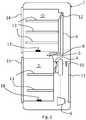
- Fig. 1 shows a no-frost refrigerating apparatus 1 as described above; it comprises a refrigerator compartment 2 and a freezer compartment 3, in fluidic communication with the evaporator 4 of the refrigerating circuit and a fan 5; the air circulated by the fan 5 laps the evaporator 4, thereby being cooled, and is then admitted into the freezer compartment 3 to refrigerate it, wherefrom it subsequently enters the refrigerator compartment 2 through a channel 6 in order to cool and dehumidify this compartment as well; circulation may be ensured in this case by a second fan 12 arranged at the end of the channel 6; it must however be specified that the second fan 12 is optional, in the sense that it may be omitted.
- the air flow coming from the freezer compartment 3 and directed to the refrigerator compartment 2 is regulated by means of an on-off valve 8 installed in the channel 6 (commonly called “damper” by those skilled in the art), which is shown herein in its simplest form, i.e. a gate that shuts off the cross-section of the channel 6.
- the position of the on-off valve 8 may vary depending on specific implementation requirements; in general, it may be located anywhere along the channel 6 that carries the air from the freezer compartment 3 to the refrigerator compartment 2: for example, if the second fan 12 is not provided, the on-off valve may be installed in its place, i.e. in that part of the channel 6 which is closest to the refrigerator compartment 2.
- the forced air circulation is conceived in a manner such that the air exiting the refrigerator compartment 2 flows back into the freezer compartment 3 through an additional return duct (not shown for clarity), which puts the refrigerator compartment 2 in fluidic communication with the freezer compartment 3, so that the air is cooled down again by the evaporator 4 and a new cycle is started.
- an on-off valve may be installed on the air return duct as well; however, the characteristics of said return duct and of its on-off valve are not important for understanding the present invention and may vary depending on specific construction requirements.
- the evaporator 4 belongs to a refrigerating circuit of a per se known type, which also includes a compressor 9, a throttling valve 10 and a condenser 11, with all the respective connection pipes (indicated by means of a dashed-dotted line in the drawing).
- Fig. 1 also shows the shelves 13 typically provided in the compartments 2 and 3, the doors 14 and 15 for closing the latter, and two temperature sensors 17 and 18 respectively arranged in the refrigerator compartment 2 and in the freezer compartment 3 and adapted to detect the air temperature, respectively T f and T c , within said compartments.
- the fans 5 and 12 and the on-off valve 8 are driven each by a respective electric motor (not shown) controlled by a control unit (not shown) which receives the temperature data read by the sensors 17 and 18 and controls the refrigerating cycle accordingly, e.g. by controlling the operation of the compressor 9.
- the control unit is inputted the temperatures T f and T c respectively detected by the sensors 17 and 18 and then controls the compressor 9, the fans 5 and 12 (if present) and the on-off valve 8 accordingly so as to keep the temperatures in both compartments 2 and 3 within preset values: the average temperature in the refrigerator compartment 2 can typically be set between 2°C and 12°C, whereas the average temperature in the freezer compartment 3 can be set between -18°C and -26°C, in both cases with an oscillation of about 4°C around the set average value.
- the compressor 9 will be started, the fans 5 and 12 will be turned on, and the on-off valve 8 will be opened (completely or partially), so as to cool down the freezer compartment 3 and partialize the cold air flow directed therefrom towards the refrigerator compartment 2, thereby adjusting the temperature thereof.
- the method of operation according to the present invention is based on the execution of at least the following steps:
- a maximum threshold temperature may be set above which the compressor 9 will be turned on, thus ending the quiet operation mode. Aiming at extending the period of quiet operation (i.e.
- the method provides for carrying out, prior to step b) as previously described, a step a) consisting of bringing the temperature of the freezer compartment 3 down to a value T inf which is lower than the normal operating temperature T cn ; this is made possible by the fact that a decrease in the temperature inside the freezer compartment 3 below the normal operating temperature T cn will cause no damage to the foodstuffs stored therein, while at the same time allowing the freezer compartment 3 to cool the air directed to the refrigerator compartment 2 for quite a long time before the temperature rising inside the freezer compartment requires that the compressor 9 be turned on again.
- T cn normal operating temperature
- step a) may be effected by using as a control quantity either the operating time of the compressor 9 or the temperature reached in the freezer compartment 3: such quantities are related in a proportional manner to each other, i.e. the longer the continuous operation of the compressor 9, the lower the temperature reached in the freezer compartment 3.
- step a) either solution may be adopted for executing step a), i.e. it is possible to choose whether the compressor 9 should operate for a preset period of time or, alternatively, until it is detected that a temperature threshold has been reached in the freezer compartment 3.
- step a) After step a) has been carried out, independently of the control quantity employed (operating time or temperature in the freezer compartment 3), the compressor 9 is turned off, thereby starting the quiet operation of the refrigerating apparatus 1: in this situation, the sensors 17 and 18 detect the temperatures T f and T c in both compartments 2 and 3 at predefined time intervals (or continuously) and send the data obtained to the control unit. Assuming that the doors 14 and 15 stay closed, the two compartments 2 and 3 will remain at optimal temperatures for a certain period of time, thanks to the gaskets and insulation provided.
- control unit When the control unit detects that the preset threshold temperature T fMAx in the refrigerator compartment 2 has been exceeded, it opens the on-off valve 8 and turns on the fan 5 and (if present) also the second fan 12 in order to carry out step c), wherein a cold air flow is taken from the freezer compartment 3 and is conveyed into the compartment at the higher temperature, i.e. the refrigerator compartment 2, until the latter reaches again a preset temperature, e.g. equal to the lower threshold value T fmin , without the help of the compressor 9, which is left off.
- a preset temperature e.g. equal to the lower threshold value T fmin
- Step c) may be carried out multiple times, at least as long as the temperature inside the freezer compartment 3 remains below the predefined maximum threshold value T sup .
- step c) may be effected either continuously or through a certain number of repetitions; in the former case, the on-off valve 8 will always stay at least partially open, and the fans 5 and 12 (if present) will be turned on (possibly at a variable revolution speed) based on the temperature values detected in the refrigerator compartment 2: if the temperature rises, the fan 5 and/or 12 will be turned on and possibly the on-off valve 8 will open a larger section of the channel 6 (in order to let more cold air flow therethrough) for the purpose of lowering the temperature in the refrigerator compartment 2; when the temperature in the latter becomes optimal, the fan 5 and/or 12 will be turned off (or, likewise, the revolution speed thereof will be reduced to the minimum), but the on-off valve 8 will stay open.
- step c) is effected by repeating the steps of opening the on-off valve 8 and activating the fan 5 and/or 12 until the threshold temperature T fmin is reached in the refrigerator compartment 2, which condition will be followed by the fan being turned off and the on-off valve 8 being closed as soon as the temperature in the refrigerator compartment 2 reaches a predefined value.
- the temperature T f in the refrigerator compartment 2 is then detected: as long as it remains below the maximum threshold T fMAX , no action will be taken.
- the temperature T f in the freezer compartment 3 will be verified: if this is lower than the upper threshold value T sup , the on-off valve 8 will be opened and the fan 5 or the second fan 12 (if present) will be turned on in order to direct a cold air flow from the freezer compartment 3 to the refrigerator compartment 2, until the temperature T f in the refrigerator compartment 2 becomes equal to the lower threshold value T fmin , at which the on-off valve 8 will be closed and the fan(s) 5 and 12 will be turned off.
- the threshold temperatures set for the refrigerator compartment 2 are equal to each other, i.e. T fmin is equal to T fMAX .
- an operating cycle is activated which comprises the steps of the method according to the present invention: during the above-described step a), the compressor 9 is turned on for a period of time of approx. 80 minutes, during which the temperature in the freezer compartment 3 drops from an initial value (in the steady state of normal operation) of approx. -18°C to a value T inf of approx. -25°C, as shown by the trend of the bundle of curves C2.
- the value of the temperature in the refrigerator compartment 2 also drops from a higher initial value to settle around a value T fMAX of approx. 4°C, as shown by the trend of the bundle of curves C1, in accordance with the above discussion.
- step b) of the above-described method is carried out, wherein the compressor 9 is turned off and the on-off valve is closed.
- the temperature T inf may be, in general, any temperature lower than T cn , although the best results are attained by setting it to a value lower than the temperature T cn by three to ten Celsius degrees, in particular six Celsius degrees.
- the threshold value T fmin varies between 0°C and 2°C
- the threshold value T fMAX varies between 4°C and 6°C
- the threshold value T sup varies between -20°C and - 16°C
- the threshold value T inf varies between -24°C and -30°C, the normal operating temperature of the freezer compartment 3 being approx. -18°C.
- the user sets the method starting instant (coinciding with the beginning of step a)) by simply pressing a button specifically intended for that purpose.
- the user sets a time interval after which the refrigerating apparatus 1 will have to start operating in quiet mode; for example, the user may want the refrigerating apparatus 1 to start operating in quiet mode after four hours, which coincides, as described above, with the fact that the compressor 9 will have to stay off after the selected time interval; in this case, the control unit of the refrigerating apparatus 1 includes a timer and controls the execution of step a) at a time preceding the time chosen by the user, so that said step will be completed at the end of the selected time interval. It must be pointed out that this mode of operation is particularly feasible when the control quantity in use for step a) is the continuous operating time of the compressor 9, as opposed to the temperature reached in the freezer compartment 3.
- the control unit includes a suitable clock or timer, and controls the execution of step a) in a manner such that it will end at the time set by the user.
- the operating time of the compressor 9 instead of the temperature reached in the freezer compartment 3 as a control quantity for step a).
- the present invention also relates to a refrigerating apparatus 1 of the type shown in and described with reference to Fig. 1 , which implements the method according to the present invention.
- the shelves 13 may be equivalently replaced with drawers or compartments; likewise, the on-off valve 8 may be of any kind (e.g. butterfly, sector or the like), provided that it is suitable for intercepting the channel 6 in order to allow the air flow carried therethrough to be adjusted.
- the channel 6 may be arranged differently than illustrated herein, for example by connecting different points of the compartments 2 and 3, without however departing from the scope and objects of the present invention.
- the on-off valve 8 may then be placed anywhere along the channel 6, e.g. even in a position adjacent to the refrigerator compartment 2.
- the fans 5 and 12 may be arranged differently than illustrated herein and, as aforementioned, the second fan 12 may be omitted.
Landscapes
- Engineering & Computer Science (AREA)
- Chemical & Material Sciences (AREA)
- Combustion & Propulsion (AREA)
- Physics & Mathematics (AREA)
- Mechanical Engineering (AREA)
- Thermal Sciences (AREA)
- General Engineering & Computer Science (AREA)
- Devices That Are Associated With Refrigeration Equipment (AREA)
- Compression-Type Refrigeration Machines With Reversible Cycles (AREA)
Description
- The present invention relates to a method of operation of a household refrigerating apparatus and to a household refrigerating apparatus implementing said method.
- It is worth stating beforehand that the term household refrigerating apparatus as used in the present description and in the appended claims refers to those refrigerating apparatuses which comprise a first cooled compartment which is typically kept at a temperature between 0 °C and 12°C (commonly called refrigerator compartment) and a second cooled compartment which is typically kept at a lower temperature between -12 °C and -35 °C (commonly called freezer compartment).
- More in particular, the present invention addresses all those refrigerating apparatuses which are commonly referred to as no-frost, wherein the cooling of the foodstuffs stored in both cells is ensured by cold air conveyed therein by a forced ventilation system; the circulating air is cooled by an evaporation-type exchanger, or evaporator, by thermal exchange with a colder refrigerating fluid circulating within a refrigerating circuit that comprises at least one compressor, one condenser and one expansion valve.
- A household refrigerating apparatus of the no-frost type as described above typically produces some operating noise mainly caused by two components: the compressor and the fan of the forced ventilation system; of these two components, the compressor is certainly the one which is more noisy (in terms of noise perceived within the apparatus installation environment), since the fan is arranged inside the apparatus, near the channels that circulate the cold air into both compartments.
- As a matter of fact, when the apparatus is operating normally, the compressor starts whenever cold air must be produced in order to maintain the preset temperature inside the cells: tests carried out have shown that the frequency of compressor intervention in a refrigerating apparatus placed in an environment at 25°C with the cell access doors closed is approximately thirty minutes of continuous operation per hour.
- It can therefore be easily understood that the frequent activation of the compressor represents a source of disturbance, in particular in all those situations where the need of reducing noise is particularly felt, e.g. during the night.
- Some solutions have been conceived in the art, such as the one described in patent
KR2001-0081331 - However, this solution is not optimal, in that the compressor must still be activated, although at lighter operating conditions, in order to keep the compartments at a preset operating temperature, and this prevents total or almost total silence from being obtained (as required, for example, when a refrigerating apparatus is to be installed near a bed in a one-room or two-room apartment).
- Another solution is disclosed in document
US5,355,686 , which discloses a method of operation of a household refrigeration apparatus according to the preamble ofclaim 1 and relates to a dual compartment single evaporator refrigerator and temperature control apparatus that controls two compartment temperatures by making the evaporator fan control independent of the control cycle. However, the solution disclosed in documentUS5,355,686 is aimed at reaching an advantage that is totally opposite to the teachings of the present invention, since said solution is aimed at reducing the risk of overcooling the freezer compartment. - The present invention aims at overcoming these and other drawbacks of the systems known in the art through a method of operation for a household refrigerating apparatus according to
claim 1. - The present invention also relates to a household refrigerating apparatus implementing said method.
- The present invention is based on the idea of using the freezer compartment (i.e. the one kept at a lower temperature than the refrigerator compartment) as a tank from which cold air can be taken and conveyed into the refrigerator compartment (operating at a higher temperature) in order to keep the latter at a preset and possibly constant temperature while keeping the compressor off, after the freezer compartment has been brought to a temperature below its normal operating temperature, which condition does not affect the quality of preservation of the foodstuffs stored in such compartment.
- This advantageously allows the compressor to stay off for a long time, approximately three to eight consecutive hours, thereby eliminating any noise related to compressor operation. Further advantageous features will be set out in the appended claims, which are intended as an integral part of the present text.
- These features as well as further advantages of the present invention will become apparent from the following description of an embodiment thereof as shown in the annexed drawings, which are supplied by way of non-limiting example, wherein:
-
Fig. 1 shows a household refrigerating apparatus; -
Fig. 2 is a flow chart of the method according to the present invention; -
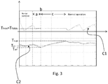
Fig. 3 shows the time trend of the temperatures in the refrigerator compartment and freezer compartment during an operating cycle according to the present invention. -
Fig. 1 shows a no-frost refrigeratingapparatus 1 as described above; it comprises a refrigerator compartment 2 and afreezer compartment 3, in fluidic communication with theevaporator 4 of the refrigerating circuit and afan 5; the air circulated by thefan 5 laps theevaporator 4, thereby being cooled, and is then admitted into thefreezer compartment 3 to refrigerate it, wherefrom it subsequently enters the refrigerator compartment 2 through achannel 6 in order to cool and dehumidify this compartment as well; circulation may be ensured in this case by asecond fan 12 arranged at the end of thechannel 6; it must however be specified that thesecond fan 12 is optional, in the sense that it may be omitted. - The air flow coming from the
freezer compartment 3 and directed to the refrigerator compartment 2 is regulated by means of an on-offvalve 8 installed in the channel 6 (commonly called "damper" by those skilled in the art), which is shown herein in its simplest form, i.e. a gate that shuts off the cross-section of thechannel 6. - The position of the on-off
valve 8 may vary depending on specific implementation requirements; in general, it may be located anywhere along thechannel 6 that carries the air from thefreezer compartment 3 to the refrigerator compartment 2: for example, if thesecond fan 12 is not provided, the on-off valve may be installed in its place, i.e. in that part of thechannel 6 which is closest to the refrigerator compartment 2. - The forced air circulation is conceived in a manner such that the air exiting the refrigerator compartment 2 flows back into the
freezer compartment 3 through an additional return duct (not shown for clarity), which puts the refrigerator compartment 2 in fluidic communication with thefreezer compartment 3, so that the air is cooled down again by theevaporator 4 and a new cycle is started. - Of course, an on-off valve may be installed on the air return duct as well; however, the characteristics of said return duct and of its on-off valve are not important for understanding the present invention and may vary depending on specific construction requirements.
- The
evaporator 4 belongs to a refrigerating circuit of a per se known type, which also includes acompressor 9, athrottling valve 10 and acondenser 11, with all the respective connection pipes (indicated by means of a dashed-dotted line in the drawing). -
Fig. 1 also shows theshelves 13 typically provided in thecompartments 2 and 3, thedoors temperature sensors freezer compartment 3 and adapted to detect the air temperature, respectively Tf and Tc, within said compartments. - The
fans valve 8 are driven each by a respective electric motor (not shown) controlled by a control unit (not shown) which receives the temperature data read by thesensors compressor 9. - In general, of course, the presence of an additional compartment will not affect the method of operation of the refrigerating
apparatus 1. - During the normal operating cycle, the control unit is inputted the temperatures Tf and Tc respectively detected by the
sensors compressor 9, thefans 5 and 12 (if present) and the on-offvalve 8 accordingly so as to keep the temperatures in bothcompartments 2 and 3 within preset values: the average temperature in the refrigerator compartment 2 can typically be set between 2°C and 12°C, whereas the average temperature in thefreezer compartment 3 can be set between -18°C and -26°C, in both cases with an oscillation of about 4°C around the set average value. - More in detail, if during a normal operating cycle the
sensors freezer compartment 3, thecompressor 9 will be started, thefans valve 8 will be opened (completely or partially), so as to cool down thefreezer compartment 3 and partialize the cold air flow directed therefrom towards the refrigerator compartment 2, thereby adjusting the temperature thereof. - In this regard, it should be pointed out that during the normal operating cycle the
fans valve 8 is made to open thechannel 6 only when thecompressor 9 is operating; as soon as the latter is switched off, thefans valve 8 will close thechannel 6. - The method of operation according to the present invention is based on the execution of at least the following steps:
- b) turning off the
compressor 9; - c) taking a cold air flow from the
freezer compartment 3 and conveying it into the refrigerator compartment 2, so as to keep the temperature of the latter within predefined minimum and maximum threshold values Tfmin and TfMAX, - Taking a cold air flow from the
freezer compartment 3 necessarily implies that the temperature of the latter will rise; for this reason, a maximum threshold temperature may be set above which thecompressor 9 will be turned on, thus ending the quiet operation mode. Aiming at extending the period of quiet operation (i.e. with thecompressor 9 switched off) of the refrigeratingapparatus 1, the method provides for carrying out, prior to step b) as previously described, a step a) consisting of bringing the temperature of thefreezer compartment 3 down to a value Tinf which is lower than the normal operating temperature Tcn; this is made possible by the fact that a decrease in the temperature inside thefreezer compartment 3 below the normal operating temperature Tcn will cause no damage to the foodstuffs stored therein, while at the same time allowing thefreezer compartment 3 to cool the air directed to the refrigerator compartment 2 for quite a long time before the temperature rising inside the freezer compartment requires that thecompressor 9 be turned on again. - More specifically, step a) is effected by keeping the
compressor 9 on for a longer time than normal: for example, if in normal operation the compressor stays on for approximately thirty minutes, in this case it may be kept on continuously for a period which may vary preferably between sixty and one hundred and eighty minutes, and anyway in a manner such that the temperature in thefreezer compartment 3 drops below the normal operating temperature Tcn (typically Tcn=-18°C), e.g. until a value Tinf in the range of -23°C to -26°C is reached, i.e. five to eight Celsius degrees less than temperature Tcn. - In this respect, it must be pointed out that step a) may be effected by using as a control quantity either the operating time of the
compressor 9 or the temperature reached in the freezer compartment 3: such quantities are related in a proportional manner to each other, i.e. the longer the continuous operation of thecompressor 9, the lower the temperature reached in thefreezer compartment 3. For the purposes of the present invention, either solution may be adopted for executing step a), i.e. it is possible to choose whether thecompressor 9 should operate for a preset period of time or, alternatively, until it is detected that a temperature threshold has been reached in thefreezer compartment 3. - After step a) has been carried out, independently of the control quantity employed (operating time or temperature in the freezer compartment 3), the
compressor 9 is turned off, thereby starting the quiet operation of the refrigerating apparatus 1: in this situation, thesensors compartments 2 and 3 at predefined time intervals (or continuously) and send the data obtained to the control unit. Assuming that thedoors compartments 2 and 3 will remain at optimal temperatures for a certain period of time, thanks to the gaskets and insulation provided. - Due to the thermal exchange with the environment surrounding the refrigerating
apparatus 1, however, the temperatures in bothcompartments 2 and 3 will tend to rise again. - In particular, after a certain time has elapsed, the temperature Tf in the refrigerator compartment 2 will rise above a set threshold value TfMAX (e.g. TfMAX=5°C); on the other hand, the temperature Tc in the
freezer compartment 3, which during step a) was brought much below the normal operating temperature (to value Tinf), will still remain for a long time at a value below a predefined threshold value Tsup, which may be chosen to be equal to the normal operating temperature Tcn (e.g. Tsup=Tcn=-18°C). - When the control unit detects that the preset threshold temperature TfMAx in the refrigerator compartment 2 has been exceeded, it opens the on-off
valve 8 and turns on thefan 5 and (if present) also thesecond fan 12 in order to carry out step c), wherein a cold air flow is taken from thefreezer compartment 3 and is conveyed into the compartment at the higher temperature, i.e. the refrigerator compartment 2, until the latter reaches again a preset temperature, e.g. equal to the lower threshold value Tfmin, without the help of thecompressor 9, which is left off. - Step c) may be carried out multiple times, at least as long as the temperature inside the
freezer compartment 3 remains below the predefined maximum threshold value Tsup. - In this regard, it should be noted that step c) may be effected either continuously or through a certain number of repetitions; in the former case, the on-off
valve 8 will always stay at least partially open, and thefans 5 and 12 (if present) will be turned on (possibly at a variable revolution speed) based on the temperature values detected in the refrigerator compartment 2: if the temperature rises, thefan 5 and/or 12 will be turned on and possibly the on-offvalve 8 will open a larger section of the channel 6 (in order to let more cold air flow therethrough) for the purpose of lowering the temperature in the refrigerator compartment 2; when the temperature in the latter becomes optimal, thefan 5 and/or 12 will be turned off (or, likewise, the revolution speed thereof will be reduced to the minimum), but the on-offvalve 8 will stay open. - As a preferable alternative, step c) is effected by repeating the steps of opening the on-off
valve 8 and activating thefan 5 and/or 12 until the threshold temperature Tfmin is reached in the refrigerator compartment 2, which condition will be followed by the fan being turned off and the on-offvalve 8 being closed as soon as the temperature in the refrigerator compartment 2 reaches a predefined value. - In any case, when the
sensor 18 detects that the temperature inside thefreezer compartment 3 has reached or exceeded a maximum threshold value (Tc≥Tsup), the quiet operation cycle will end and thecompressor 9 will be turned on again. - It must be pointed out that in optimal conditions, i.e. when the
refrigerating apparatus 1 is placed in an environment at approximately 10°C and thedoors - Tinf= -24°C
- Tsup= -18°C
- Tfmin= 0°C
- TfMAX= 4°C
- Even in less favourable conditions, e.g. when ambient temperature is 35°C, it has been discovered that this solution allows to leave the
compressor 9 off for a time longer than three consecutive hours, thus leading to a definite improvement over prior-art systems. - Of course, repeated openings of the
door 15 of thefreezer compartment 3 may heavily affect the time of operation with thecompressor 9 off. However, it is often desirable that the apparatus be quiet at nighttime, when the compartments of the refrigeratingapparatus 1 are accessed relatively seldom (or never at all), so that the behaviour of a refrigerator implementing such a method is deemed to be satisfactory. - The flow chart of the method of operation according to the present invention is shown in
Fig. 2 : the operating cycle starts with a first step of turning on thecompressor 9, which is kept on for a predefined time (condition TIMER END) or until the temperature in the freezer compartment Tc drops and becomes substantially equal to the threshold temperature Tinf (condition Tc = Tinf), after which thecompressor 9 is turned off and the on-offvalve 8 is closed. - The temperature Tf in the refrigerator compartment 2 is then detected: as long as it remains below the maximum threshold TfMAX, no action will be taken.
- When the temperature Tf rises above the maximum threshold value TfMAX, the temperature Tc in the
freezer compartment 3 will be verified: if this is lower than the upper threshold value Tsup, the on-offvalve 8 will be opened and thefan 5 or the second fan 12 (if present) will be turned on in order to direct a cold air flow from thefreezer compartment 3 to the refrigerator compartment 2, until the temperature Tf in the refrigerator compartment 2 becomes equal to the lower threshold value Tfmin, at which the on-offvalve 8 will be closed and the fan(s) 5 and 12 will be turned off. - If, on the contrary, after the temperature Tf has risen above the maximum threshold value TfMAX, it is verified that the temperature Tc in the
freezer compartment 3 is higher than the upper threshold value Tsup, then the cycle will be considered to be finished and thecompressor 9 will be turned on, the on-offvalve 8 will be opened, and thefans - According to an advantageous variant, the threshold temperatures set for the refrigerator compartment 2 are equal to each other, i.e. Tfmin is equal to TfMAX.
- In such a case, the system will still operate as described above, except that the temperature in the refrigerator compartment 2 will always be kept substantially around a single predefined value, i.e. Tfmin=TfMAX.
- In this regard, it must be pointed out that this variant also provides for changing the temperature thresholds of the refrigerator compartment 2 as the
compressor 9 is operating continuously during step a): in normal operation, as aforementioned, the cooling of the refrigerator compartment 2 is controlled in a manner such that the temperature of the latter oscillates by about 4°C around a set average value; in this variant of the method, instead, during step a) the temperature of the refrigerator compartment 2 is already set to the value Tfmin=TfMAX, i.e. the temperature threshold value to be maintained in the course of the subsequent step c), so that when the latter starts the temperature in the refrigerator compartment 2 will have already reached the value to be maintained when operating with thecompressor 9 off. - Said temperature value Tfmin=TfMAX is reached and maintained in the refrigerator compartment 2 by turning on the
fans 5 and/or 12 and by opening and closing the on-offvalve 8, so as to deliver a variable cold air flow into the refrigerator compartment 2 in order to bring it to the desired temperature Tfmin=TfMAX and keep it at that temperature. - It is important to underline that the solution provided by this variant allows to extend the time during which the
compressor 9 stays off and cold air is taken from thefreezer compartment 3; in fact, the more the instantaneous temperature inside the refrigerator compartment 2 is kept constant, the less thermal energy must be used for keeping the average temperature constant, and hence the longer the time that thecompressor 9 will stay off. - This solution is shown in
Fig. 3 , where time (expressed in hours) is indicated on the abscissas and temperature is indicated on the ordinates; the upper bundle of curves C1 shows the temperature trend in various points inside the refrigerator compartment 2, while the lower bundle of curves C2 shows the temperature trend in various points inside thefreezer compartment 3. - As can be seen, in normal operation an operating cycle is activated which comprises the steps of the method according to the present invention: during the above-described step a), the
compressor 9 is turned on for a period of time of approx. 80 minutes, during which the temperature in thefreezer compartment 3 drops from an initial value (in the steady state of normal operation) of approx. -18°C to a value Tinf of approx. -25°C, as shown by the trend of the bundle of curves C2. Within this period of time, the value of the temperature in the refrigerator compartment 2 also drops from a higher initial value to settle around a value TfMAX of approx. 4°C, as shown by the trend of the bundle of curves C1, in accordance with the above discussion. - When such values are reached, step b) of the above-described method is carried out, wherein the
compressor 9 is turned off and the on-off valve is closed. - Subsequently, for a period of about four hours, the temperature in the refrigerator compartment 2 is kept substantially constant, being (Tfmin=TfMAX) approximately equal to 5°C, by implementing step c) of the method, i.e. by taking cold air flows from the
freezer compartment 3, the temperature of which, as shown by the trend of the bundle of curves C2, rises up to the threshold value Tsup, at which step c) will end and the normal operation of the refrigeratingapparatus 1 will be resumed. - It should be noted that the temperature Tinf may be, in general, any temperature lower than Tcn, although the best results are attained by setting it to a value lower than the temperature Tcn by three to ten Celsius degrees, in particular six Celsius degrees.
- More specifically, the threshold value Tfmin varies between 0°C and 2°C, the threshold value TfMAX varies between 4°C and 6°C, the threshold value Tsup varies between -20°C and - 16°C, and the threshold value Tinf varies between -24°C and -30°C, the normal operating temperature of the
freezer compartment 3 being approx. -18°C. - As concerns the command issued by the user in order to start the method of operation described so far, three different conditions may take place, respectively coinciding with manual, semi-automatic and automatic operation.
- In the first case (manual control), the user sets the method starting instant (coinciding with the beginning of step a)) by simply pressing a button specifically intended for that purpose.
- In the second case (semi-automatic operation), the user sets a time interval after which the
refrigerating apparatus 1 will have to start operating in quiet mode; for example, the user may want the refrigeratingapparatus 1 to start operating in quiet mode after four hours, which coincides, as described above, with the fact that thecompressor 9 will have to stay off after the selected time interval; in this case, the control unit of the refrigeratingapparatus 1 includes a timer and controls the execution of step a) at a time preceding the time chosen by the user, so that said step will be completed at the end of the selected time interval. It must be pointed out that this mode of operation is particularly feasible when the control quantity in use for step a) is the continuous operating time of thecompressor 9, as opposed to the temperature reached in thefreezer compartment 3. - In the third case (automatic operation), the user sets a time at which the quiet operation mode will have to start (i.e. steps b) and c)): in this case, the control unit includes a suitable clock or timer, and controls the execution of step a) in a manner such that it will end at the time set by the user. In this case as well, it will be preferable to use the operating time of the
compressor 9 instead of the temperature reached in thefreezer compartment 3 as a control quantity for step a). - The present invention also relates to a
refrigerating apparatus 1 of the type shown in and described with reference toFig. 1 , which implements the method according to the present invention. - As a variation, it should be pointed out that, in the
refrigerating apparatus 1, theshelves 13 may be equivalently replaced with drawers or compartments; likewise, the on-offvalve 8 may be of any kind (e.g. butterfly, sector or the like), provided that it is suitable for intercepting thechannel 6 in order to allow the air flow carried therethrough to be adjusted. In turn, thechannel 6 may be arranged differently than illustrated herein, for example by connecting different points of thecompartments 2 and 3, without however departing from the scope and objects of the present invention. - The on-off
valve 8 may then be placed anywhere along thechannel 6, e.g. even in a position adjacent to the refrigerator compartment 2. - Finally, the
fans second fan 12 may be omitted.
Claims (13)
- Method of operation of a household refrigeration apparatus (1), of the type comprising at least a first (2) and a second (3) compartments for foodstuff storage, and a refrigerating circuit for cooling said compartments (2,3), wherein the refrigerating circuit comprises at least one compressor (9) and the compartments are kept at different temperatures, the first compartment (2) being a refrigerator compartment (2) kept at a higher temperature, and the second compartment (3) being a freezer compartment (3) kept at a lower temperature,
said method comprising at least the following steps:b) turning off the compressor (9) for a time interval;c) taking a cold air flow from the freezer compartment (3) and conveying it into the refrigerator compartment (2), so as to keep the temperature of the latter within a temperature range defined by a first and a second threshold values (Tfmin,TfMAX),and wherein said time interval during which the compressor (9) is off is such that the temperature in the freezer compartment (3) does not exceed a third predefined threshold value (Tsup),
characterized in that
said step b) follows a step a) wherein the temperature of the freezer compartment (3) is brought to a fourth threshold value (Tinf) which is lower than the normal operating temperature value (Tcn). - Method according to claim 1, wherein the normal operating temperature value (Tcn) of the freezer compartment (3) essentially matches said third threshold value (Tsup).
- Method according to any of the preceding claims, wherein said first and second threshold values (Tfmin,TfMAX) of the temperature in the refrigerator compartment (2) are substantially equal.
- Method according to any of the preceding claims, wherein the step c) of taking a cold air flow from the freezer compartment (3) and conveying it into the refrigerator compartment (2) so as to keep the temperature of the latter within a temperature range defined by a first and a second threshold values (Tfmin,TfMAX) is repeated several times.
- Method according to any of the preceding claims, comprising the steps of:- turning on the compressor (9) and keeping it on until the temperature (Tc) in the freezer compartment (3) reaches said fourth threshold value (Tinf) or for a predefined time interval;- turning off the compressor (9);- preventing air from passing between the refrigerator compartment (2) and the freezer compartment (3);- detecting the temperature (Tf) in the refrigerator compartment (2);- comparing said temperature value (Tf) detected in the refrigerator compartment (2) with said second threshold value (TfMAX);- if the temperature value (Tf) exceeds the maximum threshold value (TfMAX), the temperature (Tc) in the freezer compartment (3) is detected and compared with said third threshold value (Tsup) and, if the temperature value (Tc) in the freezer compartment (3) is lower than said third threshold value (Tsup): the refrigerator compartment (2) is put in fluidic communication with the freezer compartment (3), so as to transfer a cold air flow from the latter to the former, thereby cooling the refrigerator compartment until the measured temperature reaches said first threshold value (Tfmin) or until the temperature (Tc) in the freezer compartment exceeds the threshold value (Tsup);- if the temperature value (Tf) exceeds the maximum threshold value (TfMAX), the temperature (Tc) in the freezer compartment (3) is detected and compared with said third threshold value (Tsup) and, if the temperature value (Tc) in the freezer compartment (3) is higher than said third threshold value (Tsup): the compressor (9) is turned on.
- Method according to any of the preceding claims, wherein said fourth threshold value (Tinf) is lower than the normal operating temperature (Tcn) by a value between three and ten Celsius degrees, in particular six Celsius degrees.
- Method according to any of the preceding claims, wherein the first threshold value (Tfmin) varies between 0°C and 2°C, the second threshold value (TfMAX) varies between 4°C and 6°C, the third threshold value (Tsup) varies between -20°C and -16°C, the fourth threshold value (Tinf) varies between -24°C and -30°C, and the normal operating temperature of the freezer compartment (3) is approximately -18°C.
- Method according to any of the preceding claims, wherein the duration of step a) is established as a function of a control quantity, such as the temperature in the freezer compartment (3) or a time interval.
- Method according to any of the preceding claims, wherein the first threshold value (Tfmin) is equal to the second threshold value (TfMAX).
- Method according to any of the preceding claims, wherein during step a) the refrigerator compartment (2) temperature is brought to a value which is substantially equal to the first threshold value (Tfmin).
- Method according to any of the preceding claims, wherein the activation of step a) of the method is controlled by the user.
- Method according to any of claims 1 to 10, wherein the activation of step a) of the method is controlled by a control unit of the refrigeration apparatus (1) depending on an instant of activation of step b) chosen by a user, in a manner such that step a) ends when step b) is activated.
- Refrigeration apparatus (1) of the type comprising a first refrigerator compartment (2) and a second freezer compartment (3), wherein at least the freezer compartment (3) is in fluidic communication with an evaporator (4) of a refrigerating circuit comprising at least one compressor (9), one throttling valve (10) and one condenser (11), and wherein a forced circulation of air cooled by the evaporator is generated in the freezer compartment (3) by at least one fan (5), said refrigerator compartment (2) and said freezer compartment (3) being in fluidic communication with each other by means of a channel (6) intercepted by an on-off valve (8), so that the refrigerator compartment (2) is cooled by an air flow taken from the freezer compartment (3),
characterized in that
it includes a control unit configured to perform steps a), b) and c) of the method according to any of claims 1 to 12.
Priority Applications (1)
| Application Number | Priority Date | Filing Date | Title |
|---|---|---|---|
| PL10155687T PL2228614T3 (en) | 2009-03-13 | 2010-03-05 | Method of operation for a household refrigerating apparatus |
Applications Claiming Priority (1)
| Application Number | Priority Date | Filing Date | Title |
|---|---|---|---|
| ITTO2009A000193A IT1393442B1 (en) | 2009-03-13 | 2009-03-13 | METHOD OF OPERATION FOR A DOMESTIC REFRIGERANT EQUIPMENT AND TO A DOMESTIC REFRIGERANT APPARATUS THAT REALIZES THIS METHOD. |
Publications (2)
| Publication Number | Publication Date |
|---|---|
| EP2228614A1 EP2228614A1 (en) | 2010-09-15 |
| EP2228614B1 true EP2228614B1 (en) | 2018-04-25 |
Family
ID=41338907
Family Applications (1)
| Application Number | Title | Priority Date | Filing Date |
|---|---|---|---|
| EP10155687.6A Active EP2228614B1 (en) | 2009-03-13 | 2010-03-05 | Method of operation for a household refrigerating apparatus |
Country Status (4)
| Country | Link |
|---|---|
| EP (1) | EP2228614B1 (en) |
| IT (1) | IT1393442B1 (en) |
| PL (1) | PL2228614T3 (en) |
| RU (1) | RU2513416C2 (en) |
Families Citing this family (3)
| Publication number | Priority date | Publication date | Assignee | Title |
|---|---|---|---|---|
| JP5436522B2 (en) * | 2011-11-25 | 2014-03-05 | 三菱電機株式会社 | Freezer refrigerator |
| JP6254385B2 (en) * | 2013-08-29 | 2017-12-27 | アクア株式会社 | refrigerator |
| CN114992951B (en) * | 2022-05-25 | 2024-08-23 | 海信冰箱有限公司 | Refrigerator and silent control method thereof |
Family Cites Families (8)
| Publication number | Priority date | Publication date | Assignee | Title |
|---|---|---|---|---|
| US2866323A (en) * | 1955-12-27 | 1958-12-30 | Gen Motors Corp | Forced air cooled refrigerator |
| US3005321A (en) * | 1959-08-25 | 1961-10-24 | Philco Corp | Multiple temperature refrigerator |
| US3359751A (en) * | 1966-10-14 | 1967-12-26 | Admiral Corp | Two temperature refrigerator |
| US3702544A (en) * | 1970-09-25 | 1972-11-14 | Unitec Ind Inc | Refrigerator |
| US5355686A (en) * | 1993-08-11 | 1994-10-18 | Micro Weiss Electronics, Inc. | Dual temperature control of refrigerator-freezer |
| US5715703A (en) * | 1996-07-02 | 1998-02-10 | Kopf; Bruce A. | Multiple fan air distribution system for appliances |
| KR100609849B1 (en) | 2000-02-12 | 2006-08-09 | 삼성전자주식회사 | Refrigerator and its control method |
| DE10161306A1 (en) * | 2001-12-13 | 2003-06-26 | Bsh Bosch Siemens Hausgeraete | Method for controlling the moisture content of the air in a domestic frost-free refrigerator/freezer has a selector switch to vary the switching of the fan and compressor |
-
2009
- 2009-03-13 IT ITTO2009A000193A patent/IT1393442B1/en active
-
2010
- 2010-03-05 EP EP10155687.6A patent/EP2228614B1/en active Active
- 2010-03-05 PL PL10155687T patent/PL2228614T3/en unknown
- 2010-03-12 RU RU2010109436/13A patent/RU2513416C2/en not_active IP Right Cessation
Non-Patent Citations (1)
| Title |
|---|
| None * |
Also Published As
| Publication number | Publication date |
|---|---|
| ITTO20090193A1 (en) | 2010-09-14 |
| PL2228614T3 (en) | 2018-08-31 |
| RU2010109436A (en) | 2011-09-20 |
| RU2513416C2 (en) | 2014-04-20 |
| IT1393442B1 (en) | 2012-04-20 |
| EP2228614A1 (en) | 2010-09-15 |
Similar Documents
| Publication | Publication Date | Title |
|---|---|---|
| EP3093595B1 (en) | Control method of a refrigerator | |
| EP3139116A1 (en) | A refrigerator and control method thereof | |
| KR101916727B1 (en) | Refrigerator and controlling method thereof | |
| EP3531048A1 (en) | Refrigerator | |
| JP5826317B2 (en) | refrigerator | |
| US11662135B2 (en) | Refrigerator and method of controlling the same | |
| JP2004101005A (en) | Refrigerator, refrigerator operation method | |
| KR102136415B1 (en) | control method of refrigerator | |
| US11906243B2 (en) | Refrigerator and method of controlling the same | |
| CN108444176B (en) | Refrigerator and control method thereof | |
| JP2017015344A (en) | refrigerator | |
| EP2228614A1 (en) | Method of operation for a household refrigerating apparatus | |
| KR100593632B1 (en) | Method of controlling defrost cycle of refrigerator and its device | |
| KR101804629B1 (en) | Refrigerator and control method thereof | |
| CN110671884A (en) | Air supply control method for defrosting of air-cooled refrigerator and air-cooled refrigerator | |
| JP6309156B2 (en) | refrigerator | |
| JPH0989435A (en) | Refrigerator | |
| CN115727622B (en) | Refrigeration and freezing device and control method thereof | |
| CN115371330B (en) | Control method of refrigeration equipment | |
| KR100417583B1 (en) | Method for controlling heater compensating temperature of refrigerator | |
| JP2010281491A (en) | refrigerator | |
| CN109442827B (en) | Refrigeration system and refrigeration method | |
| CN119353848A (en) | Refrigerator control method, device, refrigerator and storage medium | |
| WO2024240342A1 (en) | Refrigerator with lighting | |
| CN121829004A (en) | A constant temperature freezer control system |
Legal Events
| Date | Code | Title | Description |
|---|---|---|---|
| PUAI | Public reference made under article 153(3) epc to a published international application that has entered the european phase |
Free format text: ORIGINAL CODE: 0009012 |
|
| AK | Designated contracting states |
Kind code of ref document: A1 Designated state(s): AT BE BG CH CY CZ DE DK EE ES FI FR GB GR HR HU IE IS IT LI LT LU LV MC MK MT NL NO PL PT RO SE SI SK SM TR |
|
| 17P | Request for examination filed |
Effective date: 20110310 |
|
| STAA | Information on the status of an ep patent application or granted ep patent |
Free format text: STATUS: EXAMINATION IS IN PROGRESS |
|
| RAP1 | Party data changed (applicant data changed or rights of an application transferred) |
Owner name: WHIRLPOOL EMEA S.P.A |
|
| 17Q | First examination report despatched |
Effective date: 20170213 |
|
| GRAP | Despatch of communication of intention to grant a patent |
Free format text: ORIGINAL CODE: EPIDOSNIGR1 |
|
| STAA | Information on the status of an ep patent application or granted ep patent |
Free format text: STATUS: GRANT OF PATENT IS INTENDED |
|
| INTG | Intention to grant announced |
Effective date: 20171031 |
|
| GRAS | Grant fee paid |
Free format text: ORIGINAL CODE: EPIDOSNIGR3 |
|
| GRAA | (expected) grant |
Free format text: ORIGINAL CODE: 0009210 |
|
| STAA | Information on the status of an ep patent application or granted ep patent |
Free format text: STATUS: THE PATENT HAS BEEN GRANTED |
|
| AK | Designated contracting states |
Kind code of ref document: B1 Designated state(s): AT BE BG CH CY CZ DE DK EE ES FI FR GB GR HR HU IE IS IT LI LT LU LV MC MK MT NL NO PL PT RO SE SI SK SM TR |
|
| REG | Reference to a national code |
Ref country code: GB Ref legal event code: FG4D |
|
| REG | Reference to a national code |
Ref country code: CH Ref legal event code: EP |
|
| REG | Reference to a national code |
Ref country code: AT Ref legal event code: REF Ref document number: 993362 Country of ref document: AT Kind code of ref document: T Effective date: 20180515 |
|
| REG | Reference to a national code |
Ref country code: IE Ref legal event code: FG4D |
|
| REG | Reference to a national code |
Ref country code: DE Ref legal event code: R096 Ref document number: 602010050128 Country of ref document: DE |
|
| REG | Reference to a national code |
Ref country code: NL Ref legal event code: MP Effective date: 20180425 |
|
| REG | Reference to a national code |
Ref country code: LT Ref legal event code: MG4D |
|
| PG25 | Lapsed in a contracting state [announced via postgrant information from national office to epo] |
Ref country code: NL Free format text: LAPSE BECAUSE OF FAILURE TO SUBMIT A TRANSLATION OF THE DESCRIPTION OR TO PAY THE FEE WITHIN THE PRESCRIBED TIME-LIMIT Effective date: 20180425 |
|
| PG25 | Lapsed in a contracting state [announced via postgrant information from national office to epo] |
Ref country code: ES Free format text: LAPSE BECAUSE OF FAILURE TO SUBMIT A TRANSLATION OF THE DESCRIPTION OR TO PAY THE FEE WITHIN THE PRESCRIBED TIME-LIMIT Effective date: 20180425 Ref country code: SE Free format text: LAPSE BECAUSE OF FAILURE TO SUBMIT A TRANSLATION OF THE DESCRIPTION OR TO PAY THE FEE WITHIN THE PRESCRIBED TIME-LIMIT Effective date: 20180425 Ref country code: BG Free format text: LAPSE BECAUSE OF FAILURE TO SUBMIT A TRANSLATION OF THE DESCRIPTION OR TO PAY THE FEE WITHIN THE PRESCRIBED TIME-LIMIT Effective date: 20180725 Ref country code: FI Free format text: LAPSE BECAUSE OF FAILURE TO SUBMIT A TRANSLATION OF THE DESCRIPTION OR TO PAY THE FEE WITHIN THE PRESCRIBED TIME-LIMIT Effective date: 20180425 Ref country code: NO Free format text: LAPSE BECAUSE OF FAILURE TO SUBMIT A TRANSLATION OF THE DESCRIPTION OR TO PAY THE FEE WITHIN THE PRESCRIBED TIME-LIMIT Effective date: 20180725 Ref country code: LT Free format text: LAPSE BECAUSE OF FAILURE TO SUBMIT A TRANSLATION OF THE DESCRIPTION OR TO PAY THE FEE WITHIN THE PRESCRIBED TIME-LIMIT Effective date: 20180425 |
|
| PG25 | Lapsed in a contracting state [announced via postgrant information from national office to epo] |
Ref country code: LV Free format text: LAPSE BECAUSE OF FAILURE TO SUBMIT A TRANSLATION OF THE DESCRIPTION OR TO PAY THE FEE WITHIN THE PRESCRIBED TIME-LIMIT Effective date: 20180425 Ref country code: HR Free format text: LAPSE BECAUSE OF FAILURE TO SUBMIT A TRANSLATION OF THE DESCRIPTION OR TO PAY THE FEE WITHIN THE PRESCRIBED TIME-LIMIT Effective date: 20180425 Ref country code: GR Free format text: LAPSE BECAUSE OF FAILURE TO SUBMIT A TRANSLATION OF THE DESCRIPTION OR TO PAY THE FEE WITHIN THE PRESCRIBED TIME-LIMIT Effective date: 20180726 |
|
| REG | Reference to a national code |
Ref country code: AT Ref legal event code: MK05 Ref document number: 993362 Country of ref document: AT Kind code of ref document: T Effective date: 20180425 |
|
| PG25 | Lapsed in a contracting state [announced via postgrant information from national office to epo] |
Ref country code: PT Free format text: LAPSE BECAUSE OF FAILURE TO SUBMIT A TRANSLATION OF THE DESCRIPTION OR TO PAY THE FEE WITHIN THE PRESCRIBED TIME-LIMIT Effective date: 20180827 |
|
| REG | Reference to a national code |
Ref country code: DE Ref legal event code: R097 Ref document number: 602010050128 Country of ref document: DE |
|
| PG25 | Lapsed in a contracting state [announced via postgrant information from national office to epo] |
Ref country code: EE Free format text: LAPSE BECAUSE OF FAILURE TO SUBMIT A TRANSLATION OF THE DESCRIPTION OR TO PAY THE FEE WITHIN THE PRESCRIBED TIME-LIMIT Effective date: 20180425 Ref country code: DK Free format text: LAPSE BECAUSE OF FAILURE TO SUBMIT A TRANSLATION OF THE DESCRIPTION OR TO PAY THE FEE WITHIN THE PRESCRIBED TIME-LIMIT Effective date: 20180425 Ref country code: SK Free format text: LAPSE BECAUSE OF FAILURE TO SUBMIT A TRANSLATION OF THE DESCRIPTION OR TO PAY THE FEE WITHIN THE PRESCRIBED TIME-LIMIT Effective date: 20180425 Ref country code: CZ Free format text: LAPSE BECAUSE OF FAILURE TO SUBMIT A TRANSLATION OF THE DESCRIPTION OR TO PAY THE FEE WITHIN THE PRESCRIBED TIME-LIMIT Effective date: 20180425 Ref country code: RO Free format text: LAPSE BECAUSE OF FAILURE TO SUBMIT A TRANSLATION OF THE DESCRIPTION OR TO PAY THE FEE WITHIN THE PRESCRIBED TIME-LIMIT Effective date: 20180425 Ref country code: AT Free format text: LAPSE BECAUSE OF FAILURE TO SUBMIT A TRANSLATION OF THE DESCRIPTION OR TO PAY THE FEE WITHIN THE PRESCRIBED TIME-LIMIT Effective date: 20180425 |
|
| PG25 | Lapsed in a contracting state [announced via postgrant information from national office to epo] |
Ref country code: SM Free format text: LAPSE BECAUSE OF FAILURE TO SUBMIT A TRANSLATION OF THE DESCRIPTION OR TO PAY THE FEE WITHIN THE PRESCRIBED TIME-LIMIT Effective date: 20180425 |
|
| PLBE | No opposition filed within time limit |
Free format text: ORIGINAL CODE: 0009261 |
|
| STAA | Information on the status of an ep patent application or granted ep patent |
Free format text: STATUS: NO OPPOSITION FILED WITHIN TIME LIMIT |
|
| 26N | No opposition filed |
Effective date: 20190128 |
|
| PG25 | Lapsed in a contracting state [announced via postgrant information from national office to epo] |
Ref country code: SI Free format text: LAPSE BECAUSE OF FAILURE TO SUBMIT A TRANSLATION OF THE DESCRIPTION OR TO PAY THE FEE WITHIN THE PRESCRIBED TIME-LIMIT Effective date: 20180425 |
|
| PG25 | Lapsed in a contracting state [announced via postgrant information from national office to epo] |
Ref country code: MC Free format text: LAPSE BECAUSE OF FAILURE TO SUBMIT A TRANSLATION OF THE DESCRIPTION OR TO PAY THE FEE WITHIN THE PRESCRIBED TIME-LIMIT Effective date: 20180425 |
|
| REG | Reference to a national code |
Ref country code: CH Ref legal event code: PL |
|
| PG25 | Lapsed in a contracting state [announced via postgrant information from national office to epo] |
Ref country code: LU Free format text: LAPSE BECAUSE OF NON-PAYMENT OF DUE FEES Effective date: 20190305 |
|
| REG | Reference to a national code |
Ref country code: BE Ref legal event code: MM Effective date: 20190331 |
|
| PG25 | Lapsed in a contracting state [announced via postgrant information from national office to epo] |
Ref country code: CH Free format text: LAPSE BECAUSE OF NON-PAYMENT OF DUE FEES Effective date: 20190331 Ref country code: IE Free format text: LAPSE BECAUSE OF NON-PAYMENT OF DUE FEES Effective date: 20190305 Ref country code: LI Free format text: LAPSE BECAUSE OF NON-PAYMENT OF DUE FEES Effective date: 20190331 |
|
| PG25 | Lapsed in a contracting state [announced via postgrant information from national office to epo] |
Ref country code: BE Free format text: LAPSE BECAUSE OF NON-PAYMENT OF DUE FEES Effective date: 20190331 |
|
| PGFP | Annual fee paid to national office [announced via postgrant information from national office to epo] |
Ref country code: PL Payment date: 20191212 Year of fee payment: 11 |
|
| PG25 | Lapsed in a contracting state [announced via postgrant information from national office to epo] |
Ref country code: TR Free format text: LAPSE BECAUSE OF FAILURE TO SUBMIT A TRANSLATION OF THE DESCRIPTION OR TO PAY THE FEE WITHIN THE PRESCRIBED TIME-LIMIT Effective date: 20180425 |
|
| PG25 | Lapsed in a contracting state [announced via postgrant information from national office to epo] |
Ref country code: MT Free format text: LAPSE BECAUSE OF NON-PAYMENT OF DUE FEES Effective date: 20190305 |
|
| PG25 | Lapsed in a contracting state [announced via postgrant information from national office to epo] |
Ref country code: CY Free format text: LAPSE BECAUSE OF FAILURE TO SUBMIT A TRANSLATION OF THE DESCRIPTION OR TO PAY THE FEE WITHIN THE PRESCRIBED TIME-LIMIT Effective date: 20180425 |
|
| PG25 | Lapsed in a contracting state [announced via postgrant information from national office to epo] |
Ref country code: IS Free format text: LAPSE BECAUSE OF FAILURE TO SUBMIT A TRANSLATION OF THE DESCRIPTION OR TO PAY THE FEE WITHIN THE PRESCRIBED TIME-LIMIT Effective date: 20180825 |
|
| PG25 | Lapsed in a contracting state [announced via postgrant information from national office to epo] |
Ref country code: HU Free format text: LAPSE BECAUSE OF FAILURE TO SUBMIT A TRANSLATION OF THE DESCRIPTION OR TO PAY THE FEE WITHIN THE PRESCRIBED TIME-LIMIT; INVALID AB INITIO Effective date: 20100305 |
|
| PGFP | Annual fee paid to national office [announced via postgrant information from national office to epo] |
Ref country code: GB Payment date: 20220113 Year of fee payment: 13 |
|
| PGFP | Annual fee paid to national office [announced via postgrant information from national office to epo] |
Ref country code: IT Payment date: 20220210 Year of fee payment: 13 Ref country code: FR Payment date: 20220118 Year of fee payment: 13 |
|
| PG25 | Lapsed in a contracting state [announced via postgrant information from national office to epo] |
Ref country code: MK Free format text: LAPSE BECAUSE OF FAILURE TO SUBMIT A TRANSLATION OF THE DESCRIPTION OR TO PAY THE FEE WITHIN THE PRESCRIBED TIME-LIMIT Effective date: 20180425 |
|
| PG25 | Lapsed in a contracting state [announced via postgrant information from national office to epo] |
Ref country code: PL Free format text: LAPSE BECAUSE OF NON-PAYMENT OF DUE FEES Effective date: 20210305 |
|
| P01 | Opt-out of the competence of the unified patent court (upc) registered |
Effective date: 20230523 |
|
| REG | Reference to a national code |
Ref country code: DE Ref legal event code: R081 Ref document number: 602010050128 Country of ref document: DE Owner name: WHIRLPOOL EMEA S.R.L., IT Free format text: FORMER OWNER: WHIRLPOOL EMEA S.P.A, PERO, IT |
|
| GBPC | Gb: european patent ceased through non-payment of renewal fee |
Effective date: 20230305 |
|
| PG25 | Lapsed in a contracting state [announced via postgrant information from national office to epo] |
Ref country code: GB Free format text: LAPSE BECAUSE OF NON-PAYMENT OF DUE FEES Effective date: 20230305 |
|
| PG25 | Lapsed in a contracting state [announced via postgrant information from national office to epo] |
Ref country code: GB Free format text: LAPSE BECAUSE OF NON-PAYMENT OF DUE FEES Effective date: 20230305 Ref country code: FR Free format text: LAPSE BECAUSE OF NON-PAYMENT OF DUE FEES Effective date: 20230331 |
|
| PG25 | Lapsed in a contracting state [announced via postgrant information from national office to epo] |
Ref country code: IT Free format text: LAPSE BECAUSE OF NON-PAYMENT OF DUE FEES Effective date: 20230305 |
|
| PGFP | Annual fee paid to national office [announced via postgrant information from national office to epo] |
Ref country code: DE Payment date: 20260320 Year of fee payment: 17 |