EP2228266A1 - Vehicle structures - Google Patents
Vehicle structures Download PDFInfo
- Publication number
- EP2228266A1 EP2228266A1 EP10250450A EP10250450A EP2228266A1 EP 2228266 A1 EP2228266 A1 EP 2228266A1 EP 10250450 A EP10250450 A EP 10250450A EP 10250450 A EP10250450 A EP 10250450A EP 2228266 A1 EP2228266 A1 EP 2228266A1
- Authority
- EP
- European Patent Office
- Prior art keywords
- core
- weight
- steel
- energy
- shell
- Prior art date
- Legal status (The legal status is an assumption and is not a legal conclusion. Google has not performed a legal analysis and makes no representation as to the accuracy of the status listed.)
- Withdrawn
Links
- OKTJSMMVPCPJKN-UHFFFAOYSA-N Carbon Chemical compound [C] OKTJSMMVPCPJKN-UHFFFAOYSA-N 0.000 claims abstract description 28
- 229910052799 carbon Inorganic materials 0.000 claims abstract description 26
- 229910000954 Medium-carbon steel Inorganic materials 0.000 claims abstract description 11
- 239000000463 material Substances 0.000 claims abstract description 9
- 229910000922 High-strength low-alloy steel Inorganic materials 0.000 claims abstract description 4
- IJGRMHOSHXDMSA-UHFFFAOYSA-N Atomic nitrogen Chemical compound N#N IJGRMHOSHXDMSA-UHFFFAOYSA-N 0.000 claims description 22
- 229910000831 Steel Inorganic materials 0.000 claims description 16
- 239000010959 steel Substances 0.000 claims description 16
- 229910052757 nitrogen Inorganic materials 0.000 claims description 11
- 229910052739 hydrogen Inorganic materials 0.000 claims description 10
- 239000001257 hydrogen Substances 0.000 claims description 10
- XLYOFNOQVPJJNP-UHFFFAOYSA-N water Substances O XLYOFNOQVPJJNP-UHFFFAOYSA-N 0.000 claims description 9
- UFHFLCQGNIYNRP-UHFFFAOYSA-N Hydrogen Chemical compound [H][H] UFHFLCQGNIYNRP-UHFFFAOYSA-N 0.000 claims description 7
- CURLTUGMZLYLDI-UHFFFAOYSA-N Carbon dioxide Chemical compound O=C=O CURLTUGMZLYLDI-UHFFFAOYSA-N 0.000 claims description 6
- 229910000975 Carbon steel Inorganic materials 0.000 claims description 6
- 239000010962 carbon steel Substances 0.000 claims description 6
- 238000000034 method Methods 0.000 claims description 6
- 239000000203 mixture Substances 0.000 claims description 6
- 239000001569 carbon dioxide Substances 0.000 claims description 3
- 229910002092 carbon dioxide Inorganic materials 0.000 claims description 3
- 150000002431 hydrogen Chemical class 0.000 claims description 3
- UGFAIRIUMAVXCW-UHFFFAOYSA-N Carbon monoxide Chemical compound [O+]#[C-] UGFAIRIUMAVXCW-UHFFFAOYSA-N 0.000 claims description 2
- 229910002091 carbon monoxide Inorganic materials 0.000 claims description 2
- 239000003795 chemical substances by application Substances 0.000 claims description 2
- 238000004519 manufacturing process Methods 0.000 claims description 2
- 230000003014 reinforcing effect Effects 0.000 description 7
- 230000006835 compression Effects 0.000 description 5
- 238000007906 compression Methods 0.000 description 5
- PXHVJJICTQNCMI-UHFFFAOYSA-N Nickel Chemical compound [Ni] PXHVJJICTQNCMI-UHFFFAOYSA-N 0.000 description 4
- RYGMFSIKBFXOCR-UHFFFAOYSA-N Copper Chemical compound [Cu] RYGMFSIKBFXOCR-UHFFFAOYSA-N 0.000 description 3
- 238000010521 absorption reaction Methods 0.000 description 3
- 229910052802 copper Inorganic materials 0.000 description 3
- 239000010949 copper Substances 0.000 description 3
- 208000010392 Bone Fractures Diseases 0.000 description 2
- VYZAMTAEIAYCRO-UHFFFAOYSA-N Chromium Chemical compound [Cr] VYZAMTAEIAYCRO-UHFFFAOYSA-N 0.000 description 2
- 206010017076 Fracture Diseases 0.000 description 2
- 229910001209 Low-carbon steel Inorganic materials 0.000 description 2
- PWHULOQIROXLJO-UHFFFAOYSA-N Manganese Chemical compound [Mn] PWHULOQIROXLJO-UHFFFAOYSA-N 0.000 description 2
- ZOKXTWBITQBERF-UHFFFAOYSA-N Molybdenum Chemical compound [Mo] ZOKXTWBITQBERF-UHFFFAOYSA-N 0.000 description 2
- XUIMIQQOPSSXEZ-UHFFFAOYSA-N Silicon Chemical compound [Si] XUIMIQQOPSSXEZ-UHFFFAOYSA-N 0.000 description 2
- RTAQQCXQSZGOHL-UHFFFAOYSA-N Titanium Chemical compound [Ti] RTAQQCXQSZGOHL-UHFFFAOYSA-N 0.000 description 2
- QCWXUUIWCKQGHC-UHFFFAOYSA-N Zirconium Chemical compound [Zr] QCWXUUIWCKQGHC-UHFFFAOYSA-N 0.000 description 2
- 239000011358 absorbing material Substances 0.000 description 2
- 229910052804 chromium Inorganic materials 0.000 description 2
- 239000011651 chromium Substances 0.000 description 2
- 238000002474 experimental method Methods 0.000 description 2
- 229910052748 manganese Inorganic materials 0.000 description 2
- 239000011572 manganese Substances 0.000 description 2
- 229910052750 molybdenum Inorganic materials 0.000 description 2
- 239000011733 molybdenum Substances 0.000 description 2
- 229910052759 nickel Inorganic materials 0.000 description 2
- 229910052758 niobium Inorganic materials 0.000 description 2
- 239000010955 niobium Substances 0.000 description 2
- GUCVJGMIXFAOAE-UHFFFAOYSA-N niobium atom Chemical compound [Nb] GUCVJGMIXFAOAE-UHFFFAOYSA-N 0.000 description 2
- 229910052710 silicon Inorganic materials 0.000 description 2
- 239000010703 silicon Substances 0.000 description 2
- 229910052719 titanium Inorganic materials 0.000 description 2
- 239000010936 titanium Substances 0.000 description 2
- 229910052720 vanadium Inorganic materials 0.000 description 2
- LEONUFNNVUYDNQ-UHFFFAOYSA-N vanadium atom Chemical compound [V] LEONUFNNVUYDNQ-UHFFFAOYSA-N 0.000 description 2
- 229910052726 zirconium Inorganic materials 0.000 description 2
- OYPRJOBELJOOCE-UHFFFAOYSA-N Calcium Chemical compound [Ca] OYPRJOBELJOOCE-UHFFFAOYSA-N 0.000 description 1
- 239000006096 absorbing agent Substances 0.000 description 1
- 229910045601 alloy Inorganic materials 0.000 description 1
- 239000000956 alloy Substances 0.000 description 1
- 238000005275 alloying Methods 0.000 description 1
- 230000015572 biosynthetic process Effects 0.000 description 1
- 229910052791 calcium Inorganic materials 0.000 description 1
- 239000011575 calcium Substances 0.000 description 1
- 229910017052 cobalt Inorganic materials 0.000 description 1
- 239000010941 cobalt Substances 0.000 description 1
- GUTLYIVDDKVIGB-UHFFFAOYSA-N cobalt atom Chemical compound [Co] GUTLYIVDDKVIGB-UHFFFAOYSA-N 0.000 description 1
- 230000001419 dependent effect Effects 0.000 description 1
- WPBNNNQJVZRUHP-UHFFFAOYSA-L manganese(2+);methyl n-[[2-(methoxycarbonylcarbamothioylamino)phenyl]carbamothioyl]carbamate;n-[2-(sulfidocarbothioylamino)ethyl]carbamodithioate Chemical compound [Mn+2].[S-]C(=S)NCCNC([S-])=S.COC(=O)NC(=S)NC1=CC=CC=C1NC(=S)NC(=O)OC WPBNNNQJVZRUHP-UHFFFAOYSA-L 0.000 description 1
- 238000010791 quenching Methods 0.000 description 1
- 229910052761 rare earth metal Inorganic materials 0.000 description 1
- WFKWXMTUELFFGS-UHFFFAOYSA-N tungsten Chemical compound [W] WFKWXMTUELFFGS-UHFFFAOYSA-N 0.000 description 1
- 229910052721 tungsten Inorganic materials 0.000 description 1
- 239000010937 tungsten Substances 0.000 description 1
- 238000003466 welding Methods 0.000 description 1
Images

Classifications
-
- B—PERFORMING OPERATIONS; TRANSPORTING
- B62—LAND VEHICLES FOR TRAVELLING OTHERWISE THAN ON RAILS
- B62D—MOTOR VEHICLES; TRAILERS
- B62D21/00—Understructures, i.e. chassis frame on which a vehicle body may be mounted
- B62D21/15—Understructures, i.e. chassis frame on which a vehicle body may be mounted having impact absorbing means, e.g. a frame designed to permanently or temporarily change shape or dimension upon impact with another body
-
- B—PERFORMING OPERATIONS; TRANSPORTING
- B60—VEHICLES IN GENERAL
- B60R—VEHICLES, VEHICLE FITTINGS, OR VEHICLE PARTS, NOT OTHERWISE PROVIDED FOR
- B60R19/00—Wheel guards; Radiator guards, e.g. grilles; Obstruction removers; Fittings damping bouncing force in collisions
- B60R19/02—Bumpers, i.e. impact receiving or absorbing members for protecting vehicles or fending off blows from other vehicles or objects
- B60R19/24—Arrangements for mounting bumpers on vehicles
- B60R19/26—Arrangements for mounting bumpers on vehicles comprising yieldable mounting means
- B60R19/34—Arrangements for mounting bumpers on vehicles comprising yieldable mounting means destroyed upon impact, e.g. one-shot type
-
- F—MECHANICAL ENGINEERING; LIGHTING; HEATING; WEAPONS; BLASTING
- F16—ENGINEERING ELEMENTS AND UNITS; GENERAL MEASURES FOR PRODUCING AND MAINTAINING EFFECTIVE FUNCTIONING OF MACHINES OR INSTALLATIONS; THERMAL INSULATION IN GENERAL
- F16F—SPRINGS; SHOCK-ABSORBERS; MEANS FOR DAMPING VIBRATION
- F16F7/00—Vibration-dampers; Shock-absorbers
- F16F7/12—Vibration-dampers; Shock-absorbers using plastic deformation of members
- F16F7/125—Units with a telescopic-like action as one member moves into, or out of a second member
Definitions
- This invention relates to an energy absorbing structure for a vehicle, particularly a motor vehicle (automobile).
- Energy absorbing structures are employed at the front and rear of modern motor vehicles, particularly passenger cars, so as better to absorb the energy of a crash and thus protect the driver and any passengers.
- the structures are designed such that the material of which they are formed becomes folded in a crash, thereby absorbing energy.
- an energy-absorbing structure for a vehicle comprising an energy-absorbing member that folds or crumples on crash impact, characterised in that the energy-absorbing member is of a functionally-graded material having a less ductile core integral with a more ductile shell.
- the functionally-graded material is a steel.
- the core of a steel energy-absorbing member has a first average percentage carbon content by weight and the shell of the member has a second average percentage carbon content by weight, the first average percentage carbon context by weight being greater than the second average percentage carbon content by weight.
- the core is typically hard and the shell ductile.
- the core of the energy absorbing material has an average carbon content of 0.2 - 0.59% by weight.
- the core of the energy absorbing material is of a medium carbon steel.
- a medium carbon steel typically has an average carbon content in the range of 0.30 - 0.59% by weight.
- the medium carbon steel may additionally contain one or more of manganese, silicon and copper provided that the manganese content does not exceed 1.65% by weight, the silicon content does not exceed 0.60% by weight, and the copper content does not exceed 0.60% by weight.
- the medium carbon steel is generally free of or does not require the presence of any chromium, cobalt, niobium, molybdenum, nickel, titanium, tungsten, vanadium and zirconium.
- the core of the energy absorbing medium may alternatively be of an HSLA (High Strength Low Alloy) Steel.
- HSLA High Strength Low Alloy
- Such a steel typically has a carbon content of 0.05 - 0.25% to retain formability and weldability.
- Other alloying elements include up to 2% by weight manganese and small quantities of copper, nickel, niobium, nitrogen, vanadium, chromium, molybdenum, titanium, calcium, rare earth elements or zirconium.
- the shell is of the same steel as the core, but is in partially decarburised state.
- the shell preferably has an average percentage carbon content of 0.001 % by weight to 0.15% by weight.
- the present invention also provides a method of making an energy-absorbing structure including the step of subjecting an energy-absorbing member of a carbon steel having a core integral with a shell to a controlled decarburising atmosphere for a period of time sufficient to reduce the average percentage carbon content of the shell but not the core of the member so as to render the core less ductile than the shell.
- the carbon steel may be of a medium carbon steel or an HSLA steel. Such steels are quite brittle in undecarburised state.
- the carbon steel preferably contains from 0.20 to 0.59% by weight of carbon.
- the carbon content of the shell at the end of decarburisation is preferably in the range of 0.001 to 0.15% by weight.
- the controlled decarburising atmosphere is preferably based on nitrogen, a mixture of nitrogen and hydrogen or a mixture of nitrogen, carbon monoxide and hydrogen.
- the decarburising agent is preferably water vapour. It may alternatively or additionally be carbon dioxide.
- control of the decarburising atmosphere is preferably executed by controlling the ratio by volume of hydrogen to water vapour therein.
- the ratio may be maintained in the range 10:1 to 2:1.
- the decarburising atmosphere may comprise from 4 to 10% by volume of hydrogen, 0.4 to 5% by volume of water vapour, balance nitrogen.
- the decarburising temperature is typically in the range 750 to 950°C.
- the energy-absorbing member is preferably subjected to decarburisation for up to 15 minutes, typically for 5 to 10 minutes.
- the resulting member has a pronounced shell.
- the energy absorbing structure according to the invention may comprise a front bumper or rear bumper of a motor vehicle.
- Energy absorbing structures according to the invention offer effective energy absorption in a crash with substantial resistance to fracture of the energy absorbing member. If the energy absorption member were of a uniform composition throughout, it would stand either to offer less energy absorption or a greater risk of fracture according to whether the member was, respectively, more or less ductile.
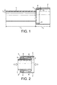
- the embodiment consists of a tubular small-diameter portion 1 and a large-diameter portion 2 on the extension from the small-diameter portion 1, formed continuously with a stepped portion 3 provided in between.
- a stepped portion 3 provided in between.
- the small-diameter portion 1 and large-diameter portion 2 which sandwich the stepped portion 3 therebetween are formed all together in one piece with a suitable rounded corner as shown.
- the configuration of such tubular bodies is such that it permits tube materials to be easily expanded and formed as by hydraulic forming.
- a reinforcing ring 4 which is formed by of a strip of mild steel or the like coiled to an annular shape either with a short gap between the cut ends or with no such gap to an endless fashion.
- the reinforcing ring 4 is secured to the inner wall surface of the large-diameter portion 2 as by spot welding.
- the portion facing the corner of the stepped portion 3 is bevelled to ensure a close contact with the latter as shown in Figure 1 .
- the wall thickness t 3 of the reinforcing ring 4 is substantially equal to or somewhat greater than the waii thickness t 1 of the small-diameter portion 1, and the width of the reinforcing portion 1 usually has a length L 1 about twice the length L 2 , of the large-diameter portion 2.
- the energy-absorbing structure according to the present invention When the energy-absorbing structure according to the present invention is compressed with a pressure P exerted from both ends, the body tends to yield and the small-diameter portion 1 is plastically forced into the large-diameter portion 2. At this time the latter remains undeformed because it is reinforced with the reinforcing ring 4 at the portion contiguous to the stepped portion 3. The portion of the small-diameter portion 1 adjacent the stepped portion 3 is guided by the end face of the reinforcing ring 4 and led thereinto, thus naturally forming a first fold 5, an intermediate-diameter portion 6. and a second fold 7, as shown in Figure 2 .
- the first fold 5 remains as it is but the second fold 7, by contrast, is displaced with the advance of the small-diameter portion 1 into the large-diameter portion 2, until the small-diameter portion 1 is turned back along the second fold 7 with inside out, thus forming the intermediate-diameter portion 6.
- the intermediate-diameter portion 6 gains length under the small-diameter portion 1 passes through the second fold 7.
- a resisting force is produced. This deformation is continuously carried out and, because the resisting force remains constant during this period, the load required for the compression is substantially constant. Throughout this the large-diameter portion 2 retains the original shape.
- the length of the intermediate-diameter portion 6 is one-half of the original length L 1 of the small-diameter portion 1, and if it is just accommodated in the large-diameter portion 2 has only to be about one-half of L 1 .
- the overall length before compression (L 1 + L 2 ) is reduced by the total of compression to L 2 , or about one-third of the original length.
- the small diameter portion 1 of the tubular body is formed of a functionally-graded steel material.
- the steel body 10 comprises an inner medium carbon core 12 and outer low carbon shell 14.
- the shell 14 is more ductile than the core 12. On impact the hard higher carbon core 12 absorbs the energy whereas the soft low carbon shell or outer layer 14 is ductile and resists crack formation.
- the core 12 is a medium carbon steel having an average carbon content in the range of 3% to 0.59% by weight.
- the shell 14 is a low carbon steel having an average carbon content in the range 0.05% to 0.15% by weight.
- the steel body 10 is preferably formed by controlled decarburisation of a uniform medium carbon steel member.
- a typical experimental procedure for performing the decarburisation is to place the tubular body of medium carbon steel in a sealed quench or other suitable furnace in which a controlled decarburising atmosphere at a suitable elevated temperature has been established. This is done by passing dry nitrogen into the furnace at a suitable rate, e.g. 2.8 m 3 /hr, the nitrogen being moisturised with water at a rate of, say, 0.21 litres per hour. Hydrogen is admitted to the furnace separately from the nitrogen at a rate sufficient to give a ratio by volume of hydrogen to water vapour in the resultant atmosphere in the range of 2:1 to 10:1. When the temperature of the atmosphere has reached a chosen value in the range 750° to 950°C the tubular steel body is loaded into the furnace.
- a suitable rate e.g. 2.8 m 3 /hr
- Hydrogen is admitted to the furnace separately from the nitrogen at a rate sufficient to give a ratio by volume of hydrogen to water vapour in the resultant atmosphere in the range of 2:1 to 10:1.
- tubular members 30 (of which only one is shown) of functionally graded steel can be used to support a bumper 40.
Landscapes
- Engineering & Computer Science (AREA)
- Mechanical Engineering (AREA)
- General Engineering & Computer Science (AREA)
- Chemical & Material Sciences (AREA)
- Combustion & Propulsion (AREA)
- Transportation (AREA)
- Vibration Dampers (AREA)
Abstract
An energy-absorbing structure (10) for a vehicle comprises an energy-absorbing member (1) that folds or crumples on crash impact, the energy-absorbing member (1) being of a functionally-graded material having a less ductile core (12) integral with a more ductile shell (14). The core is preferably of a medium carbon steel or an HSLA steel, with the shell having a lower content of carbon. The energy absorbing member may be made by partial decarburisation of a medium carbon or an HSLA steel member.
Description
- This invention relates to an energy absorbing structure for a vehicle, particularly a motor vehicle (automobile).
- Energy absorbing structures are employed at the front and rear of modern motor vehicles, particularly passenger cars, so as better to absorb the energy of a crash and thus protect the driver and any passengers. The structures are designed such that the material of which they are formed becomes folded in a crash, thereby absorbing energy.
- An example of such an energy absorbing structure is given in
US-A-5 224 574 . The performance of such an energy absorbing structure in a crash is dependent on the mechanical properties of the material, usually steel, from which it is formed. - According to the present invention there is provided an energy-absorbing structure for a vehicle comprising an energy-absorbing member that folds or crumples on crash impact, characterised in that the energy-absorbing member is of a functionally-graded material having a less ductile core integral with a more ductile shell.
- Preferably, the functionally-graded material is a steel.
- Preferably the core of a steel energy-absorbing member has a first average percentage carbon content by weight and the shell of the member has a second average percentage carbon content by weight, the first average percentage carbon context by weight being greater than the second average percentage carbon content by weight. The core is typically hard and the shell ductile.
- Preferably, the core of the energy absorbing material has an average carbon content of 0.2 - 0.59% by weight.
- The core of the energy absorbing material is of a medium carbon steel. Such a medium carbon steel typically has an average carbon content in the range of 0.30 - 0.59% by weight. The medium carbon steel may additionally contain one or more of manganese, silicon and copper provided that the manganese content does not exceed 1.65% by weight, the silicon content does not exceed 0.60% by weight, and the copper content does not exceed 0.60% by weight. The medium carbon steel is generally free of or does not require the presence of any chromium, cobalt, niobium, molybdenum, nickel, titanium, tungsten, vanadium and zirconium.
- The core of the energy absorbing medium may alternatively be of an HSLA (High Strength Low Alloy) Steel. Such a steel typically has a carbon content of 0.05 - 0.25% to retain formability and weldability. Other alloying elements include up to 2% by weight manganese and small quantities of copper, nickel, niobium, nitrogen, vanadium, chromium, molybdenum, titanium, calcium, rare earth elements or zirconium.
- Typically the shell is of the same steel as the core, but is in partially decarburised state. The shell preferably has an average percentage carbon content of 0.001 % by weight to 0.15% by weight.
- The present invention also provides a method of making an energy-absorbing structure including the step of subjecting an energy-absorbing member of a carbon steel having a core integral with a shell to a controlled decarburising atmosphere for a period of time sufficient to reduce the average percentage carbon content of the shell but not the core of the member so as to render the core less ductile than the shell.
- The carbon steel may be of a medium carbon steel or an HSLA steel. Such steels are quite brittle in undecarburised state. The carbon steel preferably contains from 0.20 to 0.59% by weight of carbon. The carbon content of the shell at the end of decarburisation is preferably in the range of 0.001 to 0.15% by weight.
- The controlled decarburising atmosphere is preferably based on nitrogen, a mixture of nitrogen and hydrogen or a mixture of nitrogen, carbon monoxide and hydrogen. The decarburising agent is preferably water vapour. It may alternatively or additionally be carbon dioxide.
- In one example of a method according to the invention the control of the decarburising atmosphere is preferably executed by controlling the ratio by volume of hydrogen to water vapour therein. For example, the ratio may be maintained in the range 10:1 to 2:1. In such an example, the decarburising atmosphere may comprise from 4 to 10% by volume of hydrogen, 0.4 to 5% by volume of water vapour, balance nitrogen.
- The decarburising temperature is typically in the range 750 to 950°C.
- The energy-absorbing member is preferably subjected to decarburisation for up to 15 minutes, typically for 5 to 10 minutes. The resulting member has a pronounced shell.
- The energy absorbing structure according to the invention may comprise a front bumper or rear bumper of a motor vehicle.
- Energy absorbing structures according to the invention offer effective energy absorption in a crash with substantial resistance to fracture of the energy absorbing member. If the energy absorption member were of a uniform composition throughout, it would stand either to offer less energy absorption or a greater risk of fracture according to whether the member was, respectively, more or less ductile.
- Structure and methods according to the present invention will now be described by way of example with reference to the accompanying drawings, in which:
-
Figure 1 is a sectional side view of an energy absorbing member for use in an energy absorbing structure according to the invention. -
Figure 2 is a sectional side view of the absorber shown inFigure 1 in a state plastically deformed by compression; -
Figure 3 is a view of an energy-absorbing structure including the member shown inFigure 1 . -
Figure 4 is a detail of the structure shown inFigure 1 . - Referring specifically to
Figures 1 and 2 , the embodiment consists of a tubular small-diameter portion 1 and a large-diameter portion 2 on the extension from the small-diameter portion 1, formed continuously with astepped portion 3 provided in between. Usually the small-diameter portion 1 and large-diameter portion 2 which sandwich thestepped portion 3 therebetween are formed all together in one piece with a suitable rounded corner as shown. The configuration of such tubular bodies is such that it permits tube materials to be easily expanded and formed as by hydraulic forming. In thestepped portion 3 there are fitted along the inner wall of the large-diameter portion 2 a reinforcingring 4 which is formed by of a strip of mild steel or the like coiled to an annular shape either with a short gap between the cut ends or with no such gap to an endless fashion. In position where it is abutted to thestepped portion 3, the reinforcingring 4 is secured to the inner wall surface of the large-diameter portion 2 as by spot welding. Of the outer periphery of the reinforcingring 4, the portion facing the corner of thestepped portion 3 is bevelled to ensure a close contact with the latter as shown inFigure 1 . The wall thickness t3 of the reinforcingring 4 is substantially equal to or somewhat greater than the waii thickness t1 of the small-diameter portion 1, and the width of the reinforcingportion 1 usually has a length L1 about twice the length L2, of the large-diameter portion 2. - When the energy-absorbing structure according to the present invention is compressed with a pressure P exerted from both ends, the body tends to yield and the small-
diameter portion 1 is plastically forced into the large-diameter portion 2. At this time the latter remains undeformed because it is reinforced with the reinforcingring 4 at the portion contiguous to thestepped portion 3. The portion of the small-diameter portion 1 adjacent thestepped portion 3 is guided by the end face of the reinforcingring 4 and led thereinto, thus naturally forming afirst fold 5, an intermediate-diameter portion 6. and asecond fold 7, as shown inFigure 2 . As the compression is kept on, thefirst fold 5 remains as it is but thesecond fold 7, by contrast, is displaced with the advance of the small-diameter portion 1 into the large-diameter portion 2, until the small-diameter portion 1 is turned back along thesecond fold 7 with inside out, thus forming the intermediate-diameter portion 6. In inverse proportion to the decrease in the length of the small-diameter portion 1, the intermediate-diameter portion 6 gains length under the small-diameter portion 1 passes through thesecond fold 7. With further plastic deformation a resisting force is produced. This deformation is continuously carried out and, because the resisting force remains constant during this period, the load required for the compression is substantially constant. Throughout this the large-diameter portion 2 retains the original shape. - Assuming that the small-
diameter portion 1 has entered completely into the large-diameter portion 2, the length of the intermediate-diameter portion 6 is one-half of the original length L1 of the small-diameter portion 1, and if it is just accommodated in the large-diameter portion 2 has only to be about one-half of L1. In other words, the overall length before compression (L1 + L2) is reduced by the total of compression to L2, or about one-third of the original length. - The
small diameter portion 1 of the tubular body is formed of a functionally-graded steel material. With reference toFigure 4 , thesteel body 10 comprises an inner medium carbon core 12 and outerlow carbon shell 14. Theshell 14 is more ductile than the core 12. On impact the hard higher carbon core 12 absorbs the energy whereas the soft low carbon shell orouter layer 14 is ductile and resists crack formation. - Typically the core 12 is a medium carbon steel having an average carbon content in the range of 3% to 0.59% by weight. Typically the
shell 14 is a low carbon steel having an average carbon content in the range 0.05% to 0.15% by weight. Thesteel body 10 is preferably formed by controlled decarburisation of a uniform medium carbon steel member. - A typical experimental procedure for performing the decarburisation is to place the tubular body of medium carbon steel in a sealed quench or other suitable furnace in which a controlled decarburising atmosphere at a suitable elevated temperature has been established. This is done by passing dry nitrogen into the furnace at a suitable rate, e.g. 2.8 m3/hr, the nitrogen being moisturised with water at a rate of, say, 0.21 litres per hour. Hydrogen is admitted to the furnace separately from the nitrogen at a rate sufficient to give a ratio by volume of hydrogen to water vapour in the resultant atmosphere in the range of 2:1 to 10:1. When the temperature of the atmosphere has reached a chosen value in the range 750° to 950°C the tubular steel body is loaded into the furnace. It is held at the chosen temperature and chosen ratio by volume of hydrogen to water vapour for a period of from 5 to 15 minutes in order to reduce the average carbon content in the outer layer of the steel body to a value in the range 0.05 to 0.15%. The requisite period of time can be determined by simple experiment. Once the tubular body has been subjected to the controlled decarburising atmosphere for the requisite period of time, it is removed from the furnace.
- Referring now to
Figure 3 , two tubular members 30 (of which only one is shown) of functionally graded steel can be used to support abumper 40.
Claims (15)
- An energy-absorbing structure for a vehicle comprising an energy-absorbing member that folds or crumples on crash impact, characterised in that the energy-absorbing member is of a functionally-graded material having a less ductile core integral with a more ductile shell.
- A structure according to claim 1, wherein the functionally-graded material is a steel.
- A structure according to claim 2, wherein the core has a first average percentage carbon content by weight and the shell has a second average percentage carbon content by weight, the first average percentage carbon content by weight being greater than the second average percentage carbon content by weight.
- A structure according to claim 2 or claim 3, wherein the core has an average percentage carbon content of 0.20% by weight to 0.59% by weight.
- A structure according to claim 4, wherein the core is of a medium carbon steel or an HSLA steel.
- A structure according to any one of the preceding claims, wherein the core is hard and the shell is ductile.
- A structure according to any one of claims 4 to 6, wherein the shell is of the same steel as the core, but is in a partially decarburised state.
- A structure according to claim 7, wherein the shell has an average percentage carbon content of 0.001 % by weight to 0.15% by weight.
- A structure according to any one of the preceding claims, wherein the structure is a support for the bumper of a vehicle.
- A motor vehicle incorporating an energy-absorbing structure according to any one of the preceding claims.
- A method of making an energy-absorbing structure according to any one of claims 1 to 9, including the step of subjecting an energy-absorbing member of carbon steel having a core integral with a shell to a controlled decarburising atmosphere for a period of time sufficient to reduce the average percentage carbon content of the shall but not the core of the member so as to render the core less ductile than the shell.
- A method according to claim 11, wherein the carbon steel contains carbon in the range of 0.20% to 0.59% by weight.
- A method according to claim 11 or 12, wherein the carbon steel is a medium carbon steel or an HLSA steel.
- A method according to any one of claims 11 to 13, wherein the controlled decarburising atmosphere is based on nitrogen, a mixture of nitrogen and hydrogen, or a mixture of nitrogen, carbon monoxide and hydrogen, the atmosphere also containing a decarburising agent selected from water vapour, carbon dioxide, and mixtures of water vapour and carbon dioxide, and decarburisation is performed at at temperature in the range 750°C to 950°C.
- A method according to claim14, wherein the decarburising atmosphere has a ratio by volume of hydrogen to water vapour in the range 10:1 to 2:1.
Applications Claiming Priority (1)
| Application Number | Priority Date | Filing Date | Title |
|---|---|---|---|
| GBGB0904343.1A GB0904343D0 (en) | 2009-03-13 | 2009-03-13 | Vehicle structures |
Publications (1)
| Publication Number | Publication Date |
|---|---|
| EP2228266A1 true EP2228266A1 (en) | 2010-09-15 |
Family
ID=40637291
Family Applications (1)
| Application Number | Title | Priority Date | Filing Date |
|---|---|---|---|
| EP10250450A Withdrawn EP2228266A1 (en) | 2009-03-13 | 2010-03-11 | Vehicle structures |
Country Status (3)
| Country | Link |
|---|---|
| US (1) | US20100230982A1 (en) |
| EP (1) | EP2228266A1 (en) |
| GB (1) | GB0904343D0 (en) |
Families Citing this family (3)
| Publication number | Priority date | Publication date | Assignee | Title |
|---|---|---|---|---|
| DE102007012962B4 (en) * | 2007-03-14 | 2013-09-05 | Benteler Automobiltechnik Gmbh | Safety device for a motor vehicle |
| EP3858684B1 (en) * | 2020-01-28 | 2025-03-05 | Outokumpu Oyj | Expanded tube for a motor vehicle crash box and manufacturing method for it |
| JP7454218B2 (en) * | 2020-03-25 | 2024-03-22 | 株式会社ニチリン | How to connect the metal fittings and socket |
Citations (2)
| Publication number | Priority date | Publication date | Assignee | Title |
|---|---|---|---|---|
| US5224574A (en) | 1991-03-16 | 1993-07-06 | Volkswagen Ag | Deformation structure, in particular for a motor vehicle |
| US20050110285A1 (en) * | 2001-09-27 | 2005-05-26 | Glasgow Scott C. | Tubular energy management system for absorbing impact energy |
Family Cites Families (26)
| Publication number | Priority date | Publication date | Assignee | Title |
|---|---|---|---|---|
| US3146014A (en) * | 1959-08-12 | 1964-08-25 | Gen Motors Corp | Energy absorbing vehicle bumper assembly |
| US3138118A (en) * | 1961-10-20 | 1964-06-23 | Budd Co | Vehicle construction for minimizing collision damage |
| JPS4745986B1 (en) * | 1967-02-25 | 1972-11-20 | ||
| US3508633A (en) * | 1967-05-17 | 1970-04-28 | Nissan Motor | Plastically deformable impact absorbing means for vehicles |
| US3599757A (en) * | 1968-06-25 | 1971-08-17 | Tokyu Car Corp | Energy absorber by means of plastic deformation |
| DE3711692A1 (en) * | 1987-04-07 | 1988-10-27 | Bayerische Motoren Werke Ag | Bumper arrangement for vehicles |
| DE3839976A1 (en) * | 1988-11-26 | 1990-05-31 | Daimler Benz Ag | BUMPER FOR VEHICLES |
| DE4316164C2 (en) * | 1993-05-14 | 1996-05-02 | Benteler Werke Ag | Bumper assembly for a motor vehicle |
| DE4417835A1 (en) * | 1994-05-20 | 1995-11-23 | Lignotock Gmbh | Shock absorber to improve safety in passenger compartments of motor vehicles |
| NL1007580C2 (en) * | 1997-11-19 | 1999-05-20 | Hoogovens Corporate Services B | Manufacture of a means for reducing the effect of an external mechanical impact and the means thus manufactured. |
| DE19803156C1 (en) * | 1998-01-28 | 1999-08-12 | Daimler Chrysler Ag | Energy absorbing mounting for vehicle bumper |
| FR2792384B1 (en) * | 1999-04-15 | 2001-06-01 | Lorraine Laminage | SHOCK ABSORBER AND MANUFACTURING METHOD |
| US6543266B1 (en) * | 1999-08-24 | 2003-04-08 | Magna International Inc. | Hydroformed collapsible driveshaft and steering shaft and methods of making the same |
| DE10042221A1 (en) * | 1999-09-02 | 2001-08-09 | Om Corp | Shock absorber for a vehicle that uses plastic deformation |
| US6293587B1 (en) * | 2000-03-17 | 2001-09-25 | Dana Corporation | Vehicle body and frame assembly including energy absorbing structure |
| JP2002331888A (en) * | 2001-05-10 | 2002-11-19 | Om Kogyo Kk | Bumper fitting structure |
| US8123263B2 (en) * | 2001-09-27 | 2012-02-28 | Shape Corp. | Energy management beam |
| JP4057837B2 (en) * | 2002-05-10 | 2008-03-05 | 株式会社アステア | Shock absorbing member |
| US6854574B2 (en) * | 2002-05-29 | 2005-02-15 | Asteer Co., Ltd. | Shock absorber |
| US7182191B2 (en) * | 2002-07-11 | 2007-02-27 | Autoliv Asp, Inc. | Motion damper |
| JP4219189B2 (en) * | 2003-02-28 | 2009-02-04 | 株式会社アステア | Bumper reinforcement support structure for body members |
| US7290783B2 (en) * | 2003-11-21 | 2007-11-06 | Shape Corporation | Towing apparatus with energy absorber |
| FR2893688B1 (en) * | 2005-11-21 | 2010-03-05 | Visteon Global Tech Inc | TRONCONIC ENERGY ABSORBER DEVICE AND FILLING ELEMENT COMPRISING SEVERAL THESE DEVICES |
| US8070197B2 (en) * | 2006-12-08 | 2011-12-06 | Cosma Engineering Europe Ag | Energy absorption device |
| US8276955B2 (en) * | 2010-03-26 | 2012-10-02 | Ford Global Technologies, Llc | Zero stack-up telescopically collapsible energy absorbing rail and bracket assembly |
| JP5587698B2 (en) * | 2010-07-30 | 2014-09-10 | アイシン精機株式会社 | Bumper device for vehicle |
-
2009
- 2009-03-13 GB GBGB0904343.1A patent/GB0904343D0/en not_active Ceased
-
2010
- 2010-03-08 US US12/719,238 patent/US20100230982A1/en not_active Abandoned
- 2010-03-11 EP EP10250450A patent/EP2228266A1/en not_active Withdrawn
Patent Citations (2)
| Publication number | Priority date | Publication date | Assignee | Title |
|---|---|---|---|---|
| US5224574A (en) | 1991-03-16 | 1993-07-06 | Volkswagen Ag | Deformation structure, in particular for a motor vehicle |
| US20050110285A1 (en) * | 2001-09-27 | 2005-05-26 | Glasgow Scott C. | Tubular energy management system for absorbing impact energy |
Also Published As
| Publication number | Publication date |
|---|---|
| GB0904343D0 (en) | 2009-04-29 |
| US20100230982A1 (en) | 2010-09-16 |
Similar Documents
| Publication | Publication Date | Title |
|---|---|---|
| CN114340980B (en) | Front structure for electric vehicle | |
| Takahashi | Development of high strength steels for automobiles | |
| US20100230982A1 (en) | Vehicle structures | |
| WO2008153480A1 (en) | Impact beam comprising precipitation hardenable stainless steel | |
| DE10353447A1 (en) | Front strut for vehicle, comprising integrated element expanding in case of impact | |
| US20170016702A1 (en) | Gas generator | |
| DE10360273B4 (en) | Protective device for a motor vehicle | |
| JP2019158028A (en) | Vehicle collision energy absorption component | |
| JP2005343329A (en) | Automotive panel structure with excellent impact energy absorption | |
| DE202004007743U1 (en) | Fastening device, in particular for a safety net arrangement for the protection of the passenger compartment of estate cars | |
| JP2007321182A (en) | Automotive parts with high shock absorption | |
| EP1854675A1 (en) | Motor vehicle bumper beam system | |
| JP2003171738A (en) | Steel tube and pressure accumulator for high-strength and tough airbag | |
| DE19918158A1 (en) | Device for reinforcing the passenger compartment of a motor vehicle | |
| US7163254B2 (en) | Folding top of a convertible automobile | |
| TWI893050B (en) | Expanded tube for a motor vehicle crash box with a working direction in a vehicle's longitudinal axis, the manufacturing method and the use as a crash box for it | |
| JPH11199929A (en) | Manufacturing method of ERW steel pipe for airbag with high strength and high dimensional accuracy | |
| Mao et al. | Reinforcement of vehicle roof structure system against rollover occupant injuries | |
| JPH0475715A (en) | Steel tube for reinforcing car body | |
| Pipkorn et al. | Proposed variable stiffness of vehicle longitudinal frontal members | |
| WO1994004713A1 (en) | Use of a steel alloy for reinforcement tubes of side doors of private cars | |
| DE102012104962A1 (en) | Roll-over protection system for motor vehicles, has beam, whose outward movement is initiated in impending crash, where beam is lockable in extended position | |
| EP1870318B1 (en) | Vehicle pillar and vehicle | |
| Otto et al. | High alloyed FeMnAlSi-steel-automotiv e lightweight potential for complex parts | |
| JP2008247280A (en) | Automotive composite member, and installation method for automotive composite member |
Legal Events
| Date | Code | Title | Description |
|---|---|---|---|
| PUAI | Public reference made under article 153(3) epc to a published international application that has entered the european phase |
Free format text: ORIGINAL CODE: 0009012 |
|
| AK | Designated contracting states |
Kind code of ref document: A1 Designated state(s): AT BE BG CH CY CZ DE DK EE ES FI FR GB GR HR HU IE IS IT LI LT LU LV MC MK MT NL NO PL PT RO SE SI SK SM TR |
|
| AX | Request for extension of the european patent |
Extension state: AL BA ME RS |
|
| 17P | Request for examination filed |
Effective date: 20110310 |
|
| STAA | Information on the status of an ep patent application or granted ep patent |
Free format text: STATUS: THE APPLICATION IS DEEMED TO BE WITHDRAWN |
|
| 18D | Application deemed to be withdrawn |
Effective date: 20110316 |