EP2226524A1 - Control method for closing a clutch in an automatic manual transmission - Google Patents
Control method for closing a clutch in an automatic manual transmission Download PDFInfo
- Publication number
- EP2226524A1 EP2226524A1 EP10155395A EP10155395A EP2226524A1 EP 2226524 A1 EP2226524 A1 EP 2226524A1 EP 10155395 A EP10155395 A EP 10155395A EP 10155395 A EP10155395 A EP 10155395A EP 2226524 A1 EP2226524 A1 EP 2226524A1
- Authority
- EP
- European Patent Office
- Prior art keywords
- clutch
- tar
- target
- determining
- acceleration
- Prior art date
- Legal status (The legal status is an assumption and is not a legal conclusion. Google has not performed a legal analysis and makes no representation as to the accuracy of the status listed.)
- Granted
Links
Images


Classifications
-
- F—MECHANICAL ENGINEERING; LIGHTING; HEATING; WEAPONS; BLASTING
- F16—ENGINEERING ELEMENTS AND UNITS; GENERAL MEASURES FOR PRODUCING AND MAINTAINING EFFECTIVE FUNCTIONING OF MACHINES OR INSTALLATIONS; THERMAL INSULATION IN GENERAL
- F16D—COUPLINGS FOR TRANSMITTING ROTATION; CLUTCHES; BRAKES
- F16D48/00—External control of clutches
- F16D48/06—Control by electric or electronic means, e.g. of fluid pressure
- F16D48/068—Control by electric or electronic means, e.g. of fluid pressure using signals from a manually actuated gearshift linkage
-
- F—MECHANICAL ENGINEERING; LIGHTING; HEATING; WEAPONS; BLASTING
- F16—ENGINEERING ELEMENTS AND UNITS; GENERAL MEASURES FOR PRODUCING AND MAINTAINING EFFECTIVE FUNCTIONING OF MACHINES OR INSTALLATIONS; THERMAL INSULATION IN GENERAL
- F16D—COUPLINGS FOR TRANSMITTING ROTATION; CLUTCHES; BRAKES
- F16D2500/00—External control of clutches by electric or electronic means
- F16D2500/10—System to be controlled
- F16D2500/108—Gear
- F16D2500/1086—Concentric shafts
-
- F—MECHANICAL ENGINEERING; LIGHTING; HEATING; WEAPONS; BLASTING
- F16—ENGINEERING ELEMENTS AND UNITS; GENERAL MEASURES FOR PRODUCING AND MAINTAINING EFFECTIVE FUNCTIONING OF MACHINES OR INSTALLATIONS; THERMAL INSULATION IN GENERAL
- F16D—COUPLINGS FOR TRANSMITTING ROTATION; CLUTCHES; BRAKES
- F16D2500/00—External control of clutches by electric or electronic means
- F16D2500/30—Signal inputs
- F16D2500/304—Signal inputs from the clutch
- F16D2500/30406—Clutch slip
-
- F—MECHANICAL ENGINEERING; LIGHTING; HEATING; WEAPONS; BLASTING
- F16—ENGINEERING ELEMENTS AND UNITS; GENERAL MEASURES FOR PRODUCING AND MAINTAINING EFFECTIVE FUNCTIONING OF MACHINES OR INSTALLATIONS; THERMAL INSULATION IN GENERAL
- F16D—COUPLINGS FOR TRANSMITTING ROTATION; CLUTCHES; BRAKES
- F16D2500/00—External control of clutches by electric or electronic means
- F16D2500/30—Signal inputs
- F16D2500/306—Signal inputs from the engine
- F16D2500/3067—Speed of the engine
-
- F—MECHANICAL ENGINEERING; LIGHTING; HEATING; WEAPONS; BLASTING
- F16—ENGINEERING ELEMENTS AND UNITS; GENERAL MEASURES FOR PRODUCING AND MAINTAINING EFFECTIVE FUNCTIONING OF MACHINES OR INSTALLATIONS; THERMAL INSULATION IN GENERAL
- F16D—COUPLINGS FOR TRANSMITTING ROTATION; CLUTCHES; BRAKES
- F16D2500/00—External control of clutches by electric or electronic means
- F16D2500/30—Signal inputs
- F16D2500/308—Signal inputs from the transmission
- F16D2500/3081—Signal inputs from the transmission from the input shaft
- F16D2500/30812—Direction of rotation of the input shaft
-
- F—MECHANICAL ENGINEERING; LIGHTING; HEATING; WEAPONS; BLASTING
- F16—ENGINEERING ELEMENTS AND UNITS; GENERAL MEASURES FOR PRODUCING AND MAINTAINING EFFECTIVE FUNCTIONING OF MACHINES OR INSTALLATIONS; THERMAL INSULATION IN GENERAL
- F16D—COUPLINGS FOR TRANSMITTING ROTATION; CLUTCHES; BRAKES
- F16D2500/00—External control of clutches by electric or electronic means
- F16D2500/50—Problem to be solved by the control system
- F16D2500/506—Relating the transmission
- F16D2500/50684—Torque resume after shifting
-
- F—MECHANICAL ENGINEERING; LIGHTING; HEATING; WEAPONS; BLASTING
- F16—ENGINEERING ELEMENTS AND UNITS; GENERAL MEASURES FOR PRODUCING AND MAINTAINING EFFECTIVE FUNCTIONING OF MACHINES OR INSTALLATIONS; THERMAL INSULATION IN GENERAL
- F16D—COUPLINGS FOR TRANSMITTING ROTATION; CLUTCHES; BRAKES
- F16D2500/00—External control of clutches by electric or electronic means
- F16D2500/70—Details about the implementation of the control system
- F16D2500/704—Output parameters from the control unit; Target parameters to be controlled
- F16D2500/70422—Clutch parameters
- F16D2500/70426—Clutch slip
-
- F—MECHANICAL ENGINEERING; LIGHTING; HEATING; WEAPONS; BLASTING
- F16—ENGINEERING ELEMENTS AND UNITS; GENERAL MEASURES FOR PRODUCING AND MAINTAINING EFFECTIVE FUNCTIONING OF MACHINES OR INSTALLATIONS; THERMAL INSULATION IN GENERAL
- F16D—COUPLINGS FOR TRANSMITTING ROTATION; CLUTCHES; BRAKES
- F16D2500/00—External control of clutches by electric or electronic means
- F16D2500/70—Details about the implementation of the control system
- F16D2500/704—Output parameters from the control unit; Target parameters to be controlled
- F16D2500/70422—Clutch parameters
- F16D2500/70426—Clutch slip
- F16D2500/70428—Clutch slip change rate
-
- F—MECHANICAL ENGINEERING; LIGHTING; HEATING; WEAPONS; BLASTING
- F16—ENGINEERING ELEMENTS AND UNITS; GENERAL MEASURES FOR PRODUCING AND MAINTAINING EFFECTIVE FUNCTIONING OF MACHINES OR INSTALLATIONS; THERMAL INSULATION IN GENERAL
- F16D—COUPLINGS FOR TRANSMITTING ROTATION; CLUTCHES; BRAKES
- F16D2500/00—External control of clutches by electric or electronic means
- F16D2500/70—Details about the implementation of the control system
- F16D2500/706—Strategy of control
- F16D2500/7061—Feed-back
- F16D2500/70626—PID control
-
- F—MECHANICAL ENGINEERING; LIGHTING; HEATING; WEAPONS; BLASTING
- F16—ENGINEERING ELEMENTS AND UNITS; GENERAL MEASURES FOR PRODUCING AND MAINTAINING EFFECTIVE FUNCTIONING OF MACHINES OR INSTALLATIONS; THERMAL INSULATION IN GENERAL
- F16H—GEARING
- F16H61/00—Control functions within control units of change-speed- or reversing-gearings for conveying rotary motion ; Control of exclusively fluid gearing, friction gearing, gearings with endless flexible members or other particular types of gearing
- F16H61/68—Control functions within control units of change-speed- or reversing-gearings for conveying rotary motion ; Control of exclusively fluid gearing, friction gearing, gearings with endless flexible members or other particular types of gearing specially adapted for stepped gearings
- F16H61/684—Control functions within control units of change-speed- or reversing-gearings for conveying rotary motion ; Control of exclusively fluid gearing, friction gearing, gearings with endless flexible members or other particular types of gearing specially adapted for stepped gearings without interruption of drive
- F16H61/688—Control functions within control units of change-speed- or reversing-gearings for conveying rotary motion ; Control of exclusively fluid gearing, friction gearing, gearings with endless flexible members or other particular types of gearing specially adapted for stepped gearings without interruption of drive with two inputs, e.g. selection of one of two torque-flow paths by clutches
Definitions
- the present invention relates to a control method for closing a clutch in an automatic manual transmission.
- AMT Automatic manual transmissions
- An automatic manual transmission is provided with a transmission control unit, which while shifting gears, drives the servo controls associated with clutch and gearbox to disengage the current gear and engage the successive gear; furthermore, while shifting gear, the transmission control unit interfaces with the engine control unit to conveniently adjust the torque delivered by the engine so as to adapt the engine operation to the transmission ratio change and to avoid an undesired temporary increase/decrease of engine rpm when the clutch is open or in all cases either while opening or closing.
- Such a control mode is applied both to traditional single clutch gearboxes and to double clutch gearboxes; the only difference between the two types of gearboxes resides in that in a single clutch gearbox there is a central interval of time in which the clutch is completely open (i.e. the engine idly turns without load), while in a double clutch gearbox the two clutches mutually cross over and therefore a clutch opening/closing situation exists during the whole shifting operation.
- a clutch has an engine side angularly integral with the drive shaft of the engine (possibly by interposing a transmission shaft) and a gearbox side, integral with a primary shaft of the gearbox, which is in turn angularly integral with the driving wheels through the currently engaged gear; the rotation speed of the two sides of the clutch is adapted when closing the clutch, because when the clutch is completely closed, the two sides of the clutch are angularly integral with each other, and thus rotate at the same rotation speed.
- the rotation speed of the driving wheels is imposed by the forward traveling speed of the vehicle, and varies with relatively long times because of the high total inertia of the vehicle itself; instead, the rotation speed of the drive shaft of the engine may be quickly varied in a controlled manner when the drive shaft is idling (i.e. when it is separated from the driving wheels) due to the low total inertia of the engine. Therefore, in the known, currently marketed automatic manual transmissions, when closing a clutch, the rpm of the drive shaft (i.e.
- US2008207393A1 describes a clutch control method which determines a torque target which is to be transmitted by the clutch during a gear shift to reduce the total time required for the gear shift itself.
- a clutch controller controls an opening degree of the clutch by driving an clutch actuator according to the difference between the torque actually transmitted by the clutch and a target of the torque transmitted by the clutch; moreover, the clutch controller determines whether a speed difference between the two sides of the clutch is reduced with an adequate acceleration and, according to such a determination, the clutch controller corrects the target of the torque transmitted by the clutch.
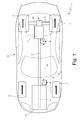
- numeral 1 indicates as a whole a vehicle (in particular, a car) provided with two front wheels 2 and two rear driving wheels 3; an internal combustion engine 4 is arranged in the frontal position, which is provided with a drive shaft 5 and produces a torque which is transmitted to the rear driving wheels 3 by means of an automatic manual transmission 6.
- Transmission 6 comprises a double clutch gearbox 7, arranged at the rear axle, and a transmission shaft 8 which connects the drive shaft 5 to an input of the gearbox 7.
- a self-locking differential 9 is arranged in cascade to gearbox 7, from which a pair of axle shafts 10 depart, each of which is integral with a rear driving wheel 3.
- Vehicle 1 comprises a control unit 11 of engine 4, which governs the engine 4, a control unit 12 of transmission 6, which governs the transmission 6, and a bus line 13, which is made according to CAN (Car Area Network) protocol, extends throughout the vehicle 1 and allows the control units 11 and 12 to interface with each other.
- the control unit 11 of engine 4 and the control unit 12 of transmission 6 are connected to the bus line 13, and may thus communicate with each other by means of messages sent on the bus line 13 itself.
- the control unit 11 of engine 4 and the control unit 12 of transmission 6 are directly connected to each other by means of a dedicated synchronization wire 14, which is capable of directly transmitting a signal without the delays introduced by the BUS line 13 from the control unit 13 of transmission 6 to the control unit 12 of engine 4.
- the double clutch gearbox 7 comprises a pair of mutually coaxial, independent primary shafts 15, inserted one within the other. Furthermore, the double clutch gearbox 7 comprises two coaxial clutches 16 arranged in series, each of which is adapted to connect a respective primary shaft 15 to the drive shaft 5 of the internal combustion engine 4 by interposing the transmission shaft 8.
- the double clutch gearbox 7 comprises a single secondary shaft 17 connected to the differential 9 which transmits motion to the rear driving wheels 3; according to an alternative, equivalent embodiment, the double clutch gearbox 7 comprises two secondary shafts 17 both connected to the differential 9.
- the double clutch gearbox 7 has seven forward speeds indicated by Roman numerals (first gear I, second gear II, third gear III, fourth gear IV, fifth gear V, sixth gear VI and seventh gear VII) and one reverse (indicated by the letter R).
- the primary shaft 15 and the secondary shaft 17 are mechanically coupled to each other by means of a plurality of gear pairs, each of which defines a respective speed and comprises a primary gear 18 mounted to the primary shaft 15 and a secondary gear 19 mounted to the secondary shaft 17.
- all the odd speeds (first gear I, third gear III, fifth gear V, seventh gear VII) are coupled to a same primary shaft 5a, while all the even speed (second gear II, fourth gear IV, and sixth gear VI) are coupled to the other primary shaft 15.
- each primary gear 18 is keyed onto a respective primary shaft 15 to again integrally rotate with the primary shaft 15 itself, and permanently meshes with the respective secondary gear 19; instead, each secondary gear 19 is idly mounted to the secondary shaft 17.
- the double clutch gearbox 7 comprises four double synchronizers 20, each of which is mounted so as to be coaxial to the secondary shaft 17, is arranged between two secondary gears 19, and is adapted to be actuated to alternatively engage the two respective secondary gears 19 onto the secondary shaft 17 (i.e. to alternatively make the two respective secondary gears 19 angularly integral with the secondary shaft 17).
- each synchronizer 20 may be displaced either in one direction to engage a secondary gear 19 onto the secondary shaft 17, or in the other direction to engage the other secondary gear 19 onto the secondary shaft 17.
- Each clutch 16 has an engine side 21 which is angularly integral with the drive shaft 5 of engine 4 by interposing a transmission shaft 8, and a gearbox side 22 which is integral with a primary shaft 15 of the gearbox 7, which in turn may be made angularly integral with the secondary shaft 17, and thus with the rear driving wheels 3 by engaging a gear.
- the two sides 21 and 22 are angularly integral with each other and thus have to rotate at the same rotation speed; instead, when each clutch 16 is at least partially open, the two sides 21 and 22 are free to rotate at two different rotation speeds.
- a clutch 16A is closed to transmit motion to a primary shaft 15A, which in turn transmits motion to the secondary shaft 17 by means of the currently engaged gear A; a clutch 16B is, instead, open and thus isolates a primary shaft 15B from the transmission shaft 8.
- the successive gear B is engaged to connect the primary shaft 15B to the secondary shaft 17 by means of the gear B itself; once the gear B has been engaged, the shifting starts by opening the clutch 16A to disconnect the primary shaft 15A (thus gear A) from the transmission shaft 8 (i.e. from the drive shaft 5 of engine 4), while closing the clutch 16B to connect the primary shaft 15B (thus gear B) to the transmission shaft 8 (i.e. to the drive shaft 5 of engine 4).
- the engine sides 21 of both clutches 16 are angularly integral with the drive shaft 5 of engine 4 by interposing the transmission shaft 8 and thus they always rotate at the same rotation speed ⁇ E as the drive shaft 5 of engine 4.
- the gearbox side 22 of clutch 16A is integral with the primary shaft 15A and until the current gear A is engaged, it rotates at a rotation speed ⁇ A which is equal to the rotation speed of the rear driving wheels 3 multiplied by the transmission ratio of the current gear A; similarly, the gearbox side 22 of the clutch 16B is integral with the primary shaft 15B and until the successive gear B is engaged, it rotates at a rotation speed ⁇ B which is equal to the rotation speed of the rear wheels 3 multiplied by the transmission ratio of the current speed B.
- a model of engine 4 and transmission 6 is determined during a step of designing the vehicle 1, which allows the behavior of engine 4 and transmission 6 to be simulated; in particular, such a model uses the transmissibility functions of the clutches 16, each of which provides the torque which is transmitted by the corresponding clutch 16 according to the opening degree (i.e. to the position when controlling the position or to the hydraulic pressure when controlling the pressure) of the clutch 16 itself.
- the control unit 12 determines a torque target T C-TAR which is to be transmitted through the clutches 16 according to the required evolution of the gear shift; in other words, the desired evolution of the gear shift is generally described by a speed target during the gear shift and by a longitudinal acceleration target during the gear shift, and according to these speed and acceleration targets, a torque target T C-TAR may be determined which is to be transmitted through the clutches 16.
- the torque target T C-TAR which is to be transmitted by the clutches 16 is equal to the sum of a torque target T CA-TAR which is to be transmitted through the clutch 16A and a torque target T CB-TAR which is to be transmitted through the clutch 16B.
- the opening degree (i.e. the position when controlling the position or the hydraulic pressure when controlling the pressure) of the clutch 16 itself is determined by using the corresponding transmissibility function; in other words, once the required evolution of the torque target T C-TAR which is to be transmitted through each clutch 16 has been determined, the evolution of the opening degree (position or hydraulic pressure) is imposed by the physical features of the clutch 16 itself and is supplied by the corresponding transmissibility function.
- the control unit 12 of transmission 6 determines a target torque T E-TAR of the engine 4 according to the torque target T C-TAR which is to be transmitted through the clutches 16; moreover, the control unit 12 of transmission 6 communicates the target torque T E-TAR of the engine 4 to the control unit 11 of engine 4 by means of the bus line 13 and/or by means of the dedicated synchronization wire 14, so that the control unit 11 of engine 4 drives the engine 4 to pursue the torque target T E-TAR of the engine 4.
- the rotation speed ⁇ E of the drive shaft 5 i.e. the rotation speed ⁇ E of the engine side 21 of clutch 16B
- the rotation speed ⁇ B of the primary shaft 15B i.e. the rotation speed ⁇ B of the gearbox side 22 of clutch 16B
- the rotation speed ⁇ E of the engine side 21 of clutch 16B is close to the rotation speed ⁇ B of the gearbox side 22 of clutch 16B, i.e. at an impact interval I in which the rotation speed ⁇ E of the engine side 21 of clutch 16B approaches the rotation speed ⁇ B of the gearbox side 22 of clutch 16B (e.g.
- a particular control mode is actuated to ensure that the connection between the rotation speed of the engine side 21 of clutch 16B and the rotation speed of the gearbox side 22 of cutch 16B is "smooth" and quick at the same time.
- the control unit 12 of transmission 6 determines a speed difference ⁇ between the rotation speed ⁇ E of the engine side 21 of clutch 16 and the rotation speed ⁇ B of the gearbox side 22 of clutch 16, thus determines an acceleration target ⁇ TAR according to the speed difference ⁇ , and finally determines the torque target T CB-TAR which is to be transmitted through the clutch 16B also according to the acceleration target ⁇ TAR .
- the acceleration target ⁇ TAR is provided by a table which is stored during a step of designing and provides a corresponding acceleration target ⁇ TAR for each speed difference ⁇ .
- the acceleration target ⁇ TAR gradually decreases as the speed difference ⁇ decreases (i.e. the smaller the speed difference ⁇ , the smaller the acceleration target ⁇ TAR ).
- the acceleration target ⁇ TAR is never completely cancelled because the speed difference ⁇ is required to be quite quickly cancelled, therefore the acceleration target ⁇ TAR must never been zero; such a result of stopping the decrease of the acceleration target ⁇ TAR is obtained, e.g. by setting that when the speed difference ⁇ is lower than a threshold, the acceleration target ⁇ TAR is then equal to a constant, predetermined value.
- a measuring sensor 23 (or, alternatively, an estimating algorithm) supplies the rotation speed ⁇ B of the gearbox side 22 of clutch 16B (i.e. the rotation speed ⁇ B of the primary shaft 15B) to the control unit 12 of transmission 6, and the control unit 11 of engine 4 supplies the rotation speed ⁇ E of the engine side 21 of clutch 16B (i.e. the rotation speed ⁇ E of the drive shaft 5) to the control unit 12 of transmission 6.
- the control unit 12 of transmission 6 determines the speed difference ⁇ between the rotation speed ⁇ E of the engine side 21 of clutch 16B and the rotation speed ⁇ B of the gearbox side 22 of clutch 16B, and thus provides the speed difference ⁇ both to a control block 24, which determines the acceleration target ⁇ TAR according to the speed difference ⁇ , and to a derivation block 25 which determines the acceleration ⁇ deriving the speed difference ⁇ over time.
- the control unit 2 of transmission 6 determines an acceleration error ⁇ by comparing the acceleration ⁇ with the acceleration target ⁇ TAR , and thus determines a first contribution T CB-TAR1 of the torque target T CB-TAR , which is to be transmitted through the clutch 16B according to the acceleration target ⁇ TAR by means of a PID regulator 26 PID which attempts to cancel the acceleration error ⁇ .
- a control block 27 of the control unit 12 of transmission 6 determines a second contribution T CB-TAR2 of the torque target T CB-TAR which is to be transmitted through the clutch 16B according to the desired evolution of the gear shift.
- the torque target T CB-TAR which is to be transmitted through the clutch 16B is determined by algebraically adding (i.e. taking the sign into account) the first contribution T CB-TAR1 of the target torque T CB-TAR which is to be transmitted through the clutch 16B to the second contribution T CB-TAR2 of the target torque T CB-TAR which is to be transmitted through the clutch 16B.
- the first contribution T CB-TAR1 of the torque target T CB-TAR which is to be transmitted through the clutch 16B is determined by means of a closed loop control (i.e. feedback control) and serves the function of conferring stability and robustness to the overall control
- the second contribution T CB-TAR2 of the torque target T CB-TAR which is to be transmitted through the clutch 16B is determined by means of an open loop control and serves the function of conferring performance (i.e. rapidity) to the overall control.
- gearbox 7 is of the single-clutch type and thus comprises only one clutch 16 and only one primary shaft 15; also in this case, the above-described control method is practically applied according to the same modes.
- the control unit 12 of transmission 6 normally determines the torque target T CB-TAR which is to be transmitted through the clutch 16B only according to the desired evolution of the position of clutch 16B; instead, when the rotation speed ⁇ E of the engine side 21 of clutch 16B is close to the rotation speed ⁇ B of the gearbox side 22 of cutch 16B, the torque target T CB-TAR which is to be transmitted through the clutch 16B is also determined according to an acceleration target ⁇ TAR which depends on the speed difference ⁇ between the rotation speed ⁇ E of the engine side 21 of clutch 16B and the rotation speed ⁇ B of the gearbox side 22 of clutch 16B.
- the above-described control method has many advantages. Firstly, a connection between the rotation speed ⁇ E of the engine side 21 of clutch 16B and the rotation speed ⁇ B of the gearbox side 22 of clutch 16B may be obtained, which is very "smooth" while being also particularly quick. Secondly, the above-described control method is simple and cost-effective to be implemented, because it does not require the installation of additional physical components, and does not results in increasing the power of the control unit 12 of transmission 6 as no high additional calculation power is needed.
Landscapes
- Engineering & Computer Science (AREA)
- General Engineering & Computer Science (AREA)
- Physics & Mathematics (AREA)
- Fluid Mechanics (AREA)
- Mechanical Engineering (AREA)
- Hydraulic Clutches, Magnetic Clutches, Fluid Clutches, And Fluid Joints (AREA)
- Control Of Transmission Device (AREA)
Abstract
Description
- The present invention relates to a control method for closing a clutch in an automatic manual transmission.
- Automatic manual transmissions (commonly named "AMT") are increasingly widespread, which transmissions are structurally similar to manual gearbox of the traditional type except for the clutch pedal and the gear selection lever operated by the driver being replaced by corresponding electric or hydraulic servo controls.
- An automatic manual transmission is provided with a transmission control unit, which while shifting gears, drives the servo controls associated with clutch and gearbox to disengage the current gear and engage the successive gear; furthermore, while shifting gear, the transmission control unit interfaces with the engine control unit to conveniently adjust the torque delivered by the engine so as to adapt the engine operation to the transmission ratio change and to avoid an undesired temporary increase/decrease of engine rpm when the clutch is open or in all cases either while opening or closing. Such a control mode is applied both to traditional single clutch gearboxes and to double clutch gearboxes; the only difference between the two types of gearboxes resides in that in a single clutch gearbox there is a central interval of time in which the clutch is completely open (i.e. the engine idly turns without load), while in a double clutch gearbox the two clutches mutually cross over and therefore a clutch opening/closing situation exists during the whole shifting operation.
- A clutch has an engine side angularly integral with the drive shaft of the engine (possibly by interposing a transmission shaft) and a gearbox side, integral with a primary shaft of the gearbox, which is in turn angularly integral with the driving wheels through the currently engaged gear; the rotation speed of the two sides of the clutch is adapted when closing the clutch, because when the clutch is completely closed, the two sides of the clutch are angularly integral with each other, and thus rotate at the same rotation speed. The rotation speed of the driving wheels is imposed by the forward traveling speed of the vehicle, and varies with relatively long times because of the high total inertia of the vehicle itself; instead, the rotation speed of the drive shaft of the engine may be quickly varied in a controlled manner when the drive shaft is idling (i.e. when it is separated from the driving wheels) due to the low total inertia of the engine. Therefore, in the known, currently marketed automatic manual transmissions, when closing a clutch, the rpm of the drive shaft (i.e. of the engine side of the clutch) is controlled according to the rpm of the gearbox side of the clutch (thus according to the rotation speed of the driving wheels, multiplied by the transmission ratio of the currently engaged gear), so as to make a connection between the rotation speed of the engine side of the clutch and the rotation speed of the gearbox side of the clutch as "smooth" as possible. Indeed, if the connection between the rotation speed of the engine side of the clutch and the rotation speed of the gearbox side of the clutch is "violent", oscillations are triggered in the transmission, which cause longitudinal vibrations on the vehicle, and are thus perceived by the driver and by possible passengers.
- However, in the known, currently marketed automatic manual transmissions, the clutch is closed very slowly in order to obtain a "smooth" connection between the rotation speed of the engine side of the clutch and the rotation speed of the gearbox side of the clutch; such a mode is effective in avoiding the onset of oscillations in the transmission, but on the other hand increases the time needed to shift gears, and thus penalizes performance. The problem is particularly evident in double clutch gearboxes, in which the clutches are in an oil bath because, while in a dry clutch used in a conventional single clutch gearbox the transmitted torque remains virtually constant despite slip variations (i.e. differences of rpm between the two sides of the clutch), in an oil bath clutch used in a double clutch gearbox, the torque transmitted by the clutch clearly drops to small slip values, and such a drop of the transmitted torque has a high dispersion from clutch to clutch. Therefore, in an oil bath clutch, controlling the torque transmitted by the clutch at small slip values (i.e. when connecting the rotation speed of the engine side of the clutch to the rotation speed of the gearbox side of the clutch is required) is very complicated.
-
US2008207393A1 describes a clutch control method which determines a torque target which is to be transmitted by the clutch during a gear shift to reduce the total time required for the gear shift itself. A clutch controller controls an opening degree of the clutch by driving an clutch actuator according to the difference between the torque actually transmitted by the clutch and a target of the torque transmitted by the clutch; moreover, the clutch controller determines whether a speed difference between the two sides of the clutch is reduced with an adequate acceleration and, according to such a determination, the clutch controller corrects the target of the torque transmitted by the clutch. - It is the object of the present invention to provide a control method for closing a clutch in an automatic manual transmission, which method is free from the above-described drawbacks while being easy and cost-effective to be implemented.
- According to the present invention, a control method for closing a clutch in an automatic manual transmission is provided as claimed in the appended claims.
- The present invention will now be described with reference to the accompanying drawings, which illustrate a non-limitative embodiment thereof, in which:
-
figure 1 is a diagrammatic plan view of a rear wheel drive vehicle provided with an automatic manual transmission which is controlled according to the control method of the present invention; -
figure 2 is a diagrammatic view of the automatic manual transmission infigure 1 , provided with a double clutch gearbox; -
figure 3 shows the time evolution of the positions of the two clutches of the double clutch gearbox and of the rotation speed of a drive shaft of the engine while shifting gear; and -
figure 4 is a block diagram of a driving logic of the manual automatic transmission infigure 1 . - In
figure 1 ,numeral 1 indicates as a whole a vehicle (in particular, a car) provided with twofront wheels 2 and tworear driving wheels 3; aninternal combustion engine 4 is arranged in the frontal position, which is provided with adrive shaft 5 and produces a torque which is transmitted to therear driving wheels 3 by means of an automaticmanual transmission 6.Transmission 6 comprises adouble clutch gearbox 7, arranged at the rear axle, and atransmission shaft 8 which connects thedrive shaft 5 to an input of thegearbox 7. A self-lockingdifferential 9 is arranged in cascade togearbox 7, from which a pair ofaxle shafts 10 depart, each of which is integral with arear driving wheel 3. -
Vehicle 1 comprises acontrol unit 11 ofengine 4, which governs theengine 4, acontrol unit 12 oftransmission 6, which governs thetransmission 6, and abus line 13, which is made according to CAN (Car Area Network) protocol, extends throughout thevehicle 1 and allows thecontrol units control unit 11 ofengine 4 and thecontrol unit 12 oftransmission 6 are connected to thebus line 13, and may thus communicate with each other by means of messages sent on thebus line 13 itself. Furthermore, thecontrol unit 11 ofengine 4 and thecontrol unit 12 oftransmission 6 are directly connected to each other by means of adedicated synchronization wire 14, which is capable of directly transmitting a signal without the delays introduced by theBUS line 13 from thecontrol unit 13 oftransmission 6 to thecontrol unit 12 ofengine 4. - As shown in
figure 2 , thedouble clutch gearbox 7 comprises a pair of mutually coaxial, independentprimary shafts 15, inserted one within the other. Furthermore, thedouble clutch gearbox 7 comprises twocoaxial clutches 16 arranged in series, each of which is adapted to connect a respectiveprimary shaft 15 to thedrive shaft 5 of theinternal combustion engine 4 by interposing thetransmission shaft 8. Thedouble clutch gearbox 7 comprises a singlesecondary shaft 17 connected to thedifferential 9 which transmits motion to therear driving wheels 3; according to an alternative, equivalent embodiment, thedouble clutch gearbox 7 comprises twosecondary shafts 17 both connected to thedifferential 9. - The
double clutch gearbox 7 has seven forward speeds indicated by Roman numerals (first gear I, second gear II, third gear III, fourth gear IV, fifth gear V, sixth gear VI and seventh gear VII) and one reverse (indicated by the letter R). Theprimary shaft 15 and thesecondary shaft 17 are mechanically coupled to each other by means of a plurality of gear pairs, each of which defines a respective speed and comprises aprimary gear 18 mounted to theprimary shaft 15 and asecondary gear 19 mounted to thesecondary shaft 17. In order to allow the correct operation of thedouble clutch gearbox 4, all the odd speeds (first gear I, third gear III, fifth gear V, seventh gear VII) are coupled to a same primary shaft 5a, while all the even speed (second gear II, fourth gear IV, and sixth gear VI) are coupled to the otherprimary shaft 15. - Each
primary gear 18 is keyed onto a respectiveprimary shaft 15 to again integrally rotate with theprimary shaft 15 itself, and permanently meshes with the respectivesecondary gear 19; instead, eachsecondary gear 19 is idly mounted to thesecondary shaft 17. Moreover, thedouble clutch gearbox 7 comprises fourdouble synchronizers 20, each of which is mounted so as to be coaxial to thesecondary shaft 17, is arranged between twosecondary gears 19, and is adapted to be actuated to alternatively engage the two respectivesecondary gears 19 onto the secondary shaft 17 (i.e. to alternatively make the two respectivesecondary gears 19 angularly integral with the secondary shaft 17). In other words, eachsynchronizer 20 may be displaced either in one direction to engage asecondary gear 19 onto thesecondary shaft 17, or in the other direction to engage the othersecondary gear 19 onto thesecondary shaft 17. - Each
clutch 16 has anengine side 21 which is angularly integral with thedrive shaft 5 ofengine 4 by interposing atransmission shaft 8, and agearbox side 22 which is integral with aprimary shaft 15 of thegearbox 7, which in turn may be made angularly integral with thesecondary shaft 17, and thus with therear driving wheels 3 by engaging a gear. When eachclutch 16 is closed, the twosides clutch 16 is at least partially open, the twosides - The modes of shifting from a current gear A to a successive gear B are described below. A shift up during the gear sequence will be described for simplicity, and therefore the current gear A has a higher transmission ratio than the successive gear B.
- In an initial situation (i.e. before shifting the gear), a
clutch 16A is closed to transmit motion to a primary shaft 15A, which in turn transmits motion to thesecondary shaft 17 by means of the currently engaged gear A; aclutch 16B is, instead, open and thus isolates a primary shaft 15B from thetransmission shaft 8. Before starting to shift up, the successive gear B is engaged to connect the primary shaft 15B to thesecondary shaft 17 by means of the gear B itself; once the gear B has been engaged, the shifting starts by opening theclutch 16A to disconnect the primary shaft 15A (thus gear A) from the transmission shaft 8 (i.e. from thedrive shaft 5 of engine 4), while closing theclutch 16B to connect the primary shaft 15B (thus gear B) to the transmission shaft 8 (i.e. to thedrive shaft 5 of engine 4). - The above-described shifting modes are diagrammatically shown in
figure 3 , which shows that before moment T1,clutch 16A is closed andclutch 16B is open, and thatclutch 16A starts opening whileclutch 16B starts closing at moment T1. At moment T2,clutch 16A is completely open whileclutch 16B is in an intermediate configuration (opening aclutch 16 is generally faster than closing it); at moment T3,clutch 16B is completely closed and then, at moment T3, theclutch 16A is opened and theclutch 16B is closed. It is thus apparent that the gear shifting starts at moment T1 and ends at moment T3. The rotation speed ωE of thedrive shaft 5 ofengine 4 is equal to the rotation speed ωA before shifting, it gradually drops towards the rotation speed ωB while shifting, and is equal to the rotation speed ωB after shifting. - As previously mentioned, the
engine sides 21 of bothclutches 16 are angularly integral with thedrive shaft 5 ofengine 4 by interposing thetransmission shaft 8 and thus they always rotate at the same rotation speed ωE as thedrive shaft 5 ofengine 4. Thegearbox side 22 ofclutch 16A is integral with the primary shaft 15A and until the current gear A is engaged, it rotates at a rotation speed ωA which is equal to the rotation speed of therear driving wheels 3 multiplied by the transmission ratio of the current gear A; similarly, thegearbox side 22 of theclutch 16B is integral with the primary shaft 15B and until the successive gear B is engaged, it rotates at a rotation speed ωB which is equal to the rotation speed of therear wheels 3 multiplied by the transmission ratio of the current speed B. By first approximation, when shifting gear, the forward traveling speed of vehicle 1 (thus the rotation speed of therear driving wheels 3 and the rotation speed of thegearbox sides 22 of both clutches 16) is assumed to remain substantially constant when shifting gear; such an assumption is quite realistic because the duration of the gear shifting is short (indicatively a few tenth of a second) and, under normal conditions, the high total mechanical inertia ofvehicle 1 does not allow large speed variations in such a short interval of time. - A model of
engine 4 andtransmission 6 is determined during a step of designing thevehicle 1, which allows the behavior ofengine 4 andtransmission 6 to be simulated; in particular, such a model uses the transmissibility functions of theclutches 16, each of which provides the torque which is transmitted by thecorresponding clutch 16 according to the opening degree (i.e. to the position when controlling the position or to the hydraulic pressure when controlling the pressure) of theclutch 16 itself. - During the whole gear shift, i.e. from the moment T1 of starting the opening of
clutch 16A corresponding to the current gear A to the moment T3 of completely closing theclutch 16B corresponding to the successive gear B, thecontrol unit 12 determines a torque target TC-TAR which is to be transmitted through theclutches 16 according to the required evolution of the gear shift; in other words, the desired evolution of the gear shift is generally described by a speed target during the gear shift and by a longitudinal acceleration target during the gear shift, and according to these speed and acceleration targets, a torque target TC-TAR may be determined which is to be transmitted through theclutches 16. It is worth noting that the torque target TC-TAR which is to be transmitted by theclutches 16 is equal to the sum of a torque target TCA-TAR which is to be transmitted through theclutch 16A and a torque target TCB-TAR which is to be transmitted through theclutch 16B. According to the torque target TC-TAR which is to be transmitted through eachclutch 16, the opening degree (i.e. the position when controlling the position or the hydraulic pressure when controlling the pressure) of theclutch 16 itself is determined by using the corresponding transmissibility function; in other words, once the required evolution of the torque target TC-TAR which is to be transmitted through eachclutch 16 has been determined, the evolution of the opening degree (position or hydraulic pressure) is imposed by the physical features of theclutch 16 itself and is supplied by the corresponding transmissibility function. - During the whole gear shifting, i.e. from the moment T1 of starting the opening of the
clutch 16A corresponding to current gear A to the moment T3 of completely closing theclutch 16B corresponding to the successive gear B, thecontrol unit 12 oftransmission 6 determines a target torque TE-TAR of theengine 4 according to the torque target TC-TAR which is to be transmitted through theclutches 16; moreover, thecontrol unit 12 oftransmission 6 communicates the target torque TE-TAR of theengine 4 to thecontrol unit 11 ofengine 4 by means of thebus line 13 and/or by means of thededicated synchronization wire 14, so that thecontrol unit 11 ofengine 4 drives theengine 4 to pursue the torque target TE-TAR of theengine 4. - As shown in
figure 3 , until moment T2 in which theclutch 16A is completely open, the rotation speed ωE of the drive shaft 5 (i.e. the rotation speed ωE of theengine side 21 ofclutch 16B) is kept constant and equal to the rotation speed ωA and is thus decreased only once theclutch 16A has been completely opened; such a control mode of the rotation speed ωE of thedrive shaft 5 is aimed at avoiding theclutch 16A from becoming braking, i.e. from generating a braking torque on therear driving wheels 3. - After moment T2, the rotation speed ωE of the drive shaft 5 (i.e. the rotation speed ωE of the
engine side 21 ofclutch 16B) is gradually decreased to reach the rotation speed ωB of the primary shaft 15B (i.e. the rotation speed ωB of thegearbox side 22 ofclutch 16B) as quickly as possible; when the rotation speed ωE of theengine side 21 ofclutch 16B is close to the rotation speed ωB of thegearbox side 22 ofclutch 16B, i.e. at an impact interval I in which the rotation speed ωE of theengine side 21 ofclutch 16B approaches the rotation speed ωB of thegearbox side 22 ofclutch 16B (e.g. when the speed difference Δω is lower than a threshold which may take the value of 250 rpm), a particular control mode is actuated to ensure that the connection between the rotation speed of theengine side 21 ofclutch 16B and the rotation speed of thegearbox side 22 of cutch 16B is "smooth" and quick at the same time. - As shown in
figure 4 , when the rotation speed ωE of theengine side 21 ofclutch 16B (i.e. the rotation speed ωE of the drive shaft 5) is close to the rotation speed ωB of thegearbox side 22 ofclutch 16B (i.e. to the rotation speed ωB of the primary shaft 15B), thus at an impact interval I in which the rotation speed ωE of theengine side 21 ofclutch 16B approaches the rotation speed ωB of thegearbox side 22 ofclutch 16B, thecontrol unit 12 oftransmission 6 determines a speed difference Δω between the rotation speed ωE of theengine side 21 ofclutch 16 and the rotation speed ωB of thegearbox side 22 ofclutch 16, thus determines an acceleration target αTAR according to the speed difference Δω, and finally determines the torque target TCB-TAR which is to be transmitted through theclutch 16B also according to the acceleration target αTAR. For example, the acceleration target αTAR is provided by a table which is stored during a step of designing and provides a corresponding acceleration target αTAR for each speed difference Δω. In general, the acceleration target αTAR gradually decreases as the speed difference Δω decreases (i.e. the smaller the speed difference Δω, the smaller the acceleration target αTAR). Obviously, the acceleration target αTAR is never completely cancelled because the speed difference Δω is required to be quite quickly cancelled, therefore the acceleration target αTAR must never been zero; such a result of stopping the decrease of the acceleration target αTAR is obtained, e.g. by setting that when the speed difference Δω is lower than a threshold, the acceleration target αTAR is then equal to a constant, predetermined value. - In particular, a measuring sensor 23 (or, alternatively, an estimating algorithm) supplies the rotation speed ωB of the
gearbox side 22 ofclutch 16B (i.e. the rotation speed ωB of the primary shaft 15B) to thecontrol unit 12 oftransmission 6, and thecontrol unit 11 ofengine 4 supplies the rotation speed ωE of theengine side 21 ofclutch 16B (i.e. the rotation speed ωE of the drive shaft 5) to thecontrol unit 12 oftransmission 6. Thecontrol unit 12 oftransmission 6 determines the speed difference Δω between the rotation speed ωE of theengine side 21 ofclutch 16B and the rotation speed ωB of thegearbox side 22 ofclutch 16B, and thus provides the speed difference Δω both to acontrol block 24, which determines the acceleration target αTAR according to the speed difference Δω, and to aderivation block 25 which determines the acceleration α deriving the speed difference Δω over time. Thecontrol unit 2 oftransmission 6 determines an acceleration error εα by comparing the acceleration α with the acceleration target αTAR, and thus determines a first contribution TCB-TAR1 of the torque target TCB-TAR, which is to be transmitted through the clutch 16B according to the acceleration target αTAR by means of aPID regulator 26 PID which attempts to cancel the acceleration error εα. - A
control block 27 of thecontrol unit 12 oftransmission 6 determines a second contribution TCB-TAR2 of the torque target TCB-TAR which is to be transmitted through the clutch 16B according to the desired evolution of the gear shift. The torque target TCB-TAR which is to be transmitted through the clutch 16B is determined by algebraically adding (i.e. taking the sign into account) the first contribution TCB-TAR1 of the target torque TCB-TAR which is to be transmitted through the clutch 16B to the second contribution TCB-TAR2 of the target torque TCB-TAR which is to be transmitted through the clutch 16B. From the above description, it is apparent that the first contribution TCB-TAR1 of the torque target TCB-TAR which is to be transmitted through the clutch 16B is determined by means of a closed loop control (i.e. feedback control) and serves the function of conferring stability and robustness to the overall control, while the second contribution TCB-TAR2 of the torque target TCB-TAR which is to be transmitted through the clutch 16B is determined by means of an open loop control and serves the function of conferring performance (i.e. rapidity) to the overall control. By varying the weight of the two contributions TCB-TAR1 and TCB-TAR2 of the torque objective TCB-TAR which is to be transmitted through the clutch 16B, robustness (and thus comfort) or performance (thus rapidity) may be favoured. - According to an alternative embodiment (not shown)
gearbox 7 is of the single-clutch type and thus comprises only one clutch 16 and only oneprimary shaft 15; also in this case, the above-described control method is practically applied according to the same modes. - To summarize the above, the
control unit 12 oftransmission 6 normally determines the torque target TCB-TAR which is to be transmitted through the clutch 16B only according to the desired evolution of the position of clutch 16B; instead, when the rotation speed ωE of theengine side 21 of clutch 16B is close to the rotation speed ωB of thegearbox side 22 ofcutch 16B, the torque target TCB-TAR which is to be transmitted through the clutch 16B is also determined according to an acceleration target αTAR which depends on the speed difference Δω between the rotation speed ωE of theengine side 21 ofclutch 16B and the rotation speed ωB of thegearbox side 22 ofclutch 16B. Thereby, a connection between the rotation speed ωE of theengine side 21 ofclutch 16B and the rotation speed ωB of thegearbox side 22 of clutch 16B may be obtained, which is very "smooth" while being also particularly quick. Furthermore, it is very simple to calibrate such a connection to favour either "smoothness" or rapidity according to the driving style chosen by the driver (e.g. sporty or comfortable style) simply by adjusting the parameters of thecalculation block 24 which determines the acceleration target αTAR according to the speed difference Δω. - In brief, the above-described control method has many advantages. Firstly, a connection between the rotation speed ωE of the
engine side 21 ofclutch 16B and the rotation speed ωB of thegearbox side 22 of clutch 16B may be obtained, which is very "smooth" while being also particularly quick. Secondly, the above-described control method is simple and cost-effective to be implemented, because it does not require the installation of additional physical components, and does not results in increasing the power of thecontrol unit 12 oftransmission 6 as no high additional calculation power is needed.
Claims (11)
- A control method for closing a clutch (16B) in an automatic manual transmission (6) during a gear shifting to pass from a current gear (A) to a successive gear (B); the automatic gear transmission (6) comprises a gearbox (7), which is provided with at least one primary shaft (15) and at least one secondary shaft (17) connected to driving wheels (3), and at least one clutch (16B), which is interposed between the primary shaft (15) of the gearbox (7) and a drive shaft (5) of an engine (4); the control method comprises, only when, during the closing of the clutch (16B), the rotation speed (ωE) of an engine side (21) of the clutch (16B) is close to the rotation speed (ωB) of a gearbox side (22) of the clutch (16B), the steps of:determining a speed difference (Δω) between the rotation speed (ωE) of the engine side (21) of the clutch (16B) and the rotation speed (ωB) of the gearbox side (22) of the clutch (16B);determining an acceleration target (αTAR) according to the speed difference (Δω) so that the acceleration target (αTAR) progressively decreases as the speed difference (Δω) decreases; anddetermining a target torque (TCB-TAR) that has to be transmitted through the clutch (16B) according to the acceleration target (αTAR).
- The control method according to claim 1 and comprising the further steps of:determining an acceleration (α) by deriving in time the speed difference (Δω);determining an acceleration error (εα) by comparing the acceleration (α) with the acceleration target (αTAR); anddetermining the target torque (TCB-TAR) that has to be transmitted through the clutch (16B) according to the acceleration error (εα).
- The control method according to claim 2 and comprising the further step of determining the target torque (TCB-TAR) that has to be transmitted through the clutch (16B) by means of a PID regulator (26) which tries to cancel the acceleration error (εα).
- The control method according to claim 1, 2 or 3 and comprising the further steps of:determining a first contribution (TCB-TAR1) of the target torque (TCB-TAR) that has to be transmitted through the clutch (16B) according to the acceleration target (αTAR);determining a second contribution (TCB-TAR2) of the target torque (TCB-TAR) that has to be transmitted through the clutch (16B); andadding algebraically the first contribution (TCB-TAR1) of the target torque (TCB-TAR) that has to be transmitted through the clutch (16B) to the second contribution (TCB-TAR2) of the target torque (TCB-TAR) that has to be transmitted through the clutch (16B), in order to determine the target torque (TCB-TAR) that has to be transmitted through the clutch (16B).
- The control method according to claim 4 and comprising the further step of determining the second contribution (TCB-TAR2) of the target torque (TCB-TAR) that has to be transmitted through the clutch (16B) by means of an open-loop control.
- The control method according to claim 4 or 5 and comprising the further step of determining the first contribution (TCB-TAR1) of the target torque (TCB-TAR) that has to be transmitted through the clutch (16B) by means of a closed-loop control.
- The control method according to claim 6 and comprising the further steps of:determining an acceleration (α) by deriving in time the speed difference (Δω);determining an acceleration error (εα) by comparing the acceleration (α) with the acceleration target (αTAR); anddetermining the first contribution (TCB-TAR1) of the target torque (TCB-TAR) that has to be transmitted through the clutch (16B) according to the acceleration error (εα).
- The control method according to one of the claims from 1 to 7 and comprising the further steps of:determining a target engine torque (TE-TAR) of the engine (4) according to the target torque (TCB-TAR) that has to be transmitted through the clutch (16B); andmaking the engine (4) pursue the target engine torque (TE-TAR) of the engine (4).
- The control method according to one of the claims from 1 to 8, wherein the gearbox (7) is a double clutch gearbox and comprises two primary shafts (15) and two clutches (16), each of which is interposed between the drive shaft (5) of the engine (4) and a corresponding primary shaft (15).
- The control method according to one of the claims from 1 to 9 and comprising the further step of assigning to the acceleration target (αTAR) a constant value when the speed difference (Δω) is lower than a first threshold.
- The control method according to one of the claims from 1 to 10 and comprising the further step of judging the rotation speed (ωE) of an engine side (21) of the clutch (16B) close to the rotation speed (ωB) of a gearbox side (22) of the clutch (16B) when the speed difference (Δω) is lower than a second threshold.
Applications Claiming Priority (1)
| Application Number | Priority Date | Filing Date | Title |
|---|---|---|---|
| ITBO2009A000127A IT1394918B1 (en) | 2009-03-04 | 2009-03-04 | CONTROL METHOD FOR CLOSING A CLUTCH IN AN AUTOMATIC MANUAL TRANSMISSION |
Publications (2)
| Publication Number | Publication Date |
|---|---|
| EP2226524A1 true EP2226524A1 (en) | 2010-09-08 |
| EP2226524B1 EP2226524B1 (en) | 2013-09-18 |
Family
ID=41278571
Family Applications (1)
| Application Number | Title | Priority Date | Filing Date |
|---|---|---|---|
| EP10155395.6A Active EP2226524B1 (en) | 2009-03-04 | 2010-03-03 | Control method for closing a clutch in an automatic manual transmission |
Country Status (3)
| Country | Link |
|---|---|
| US (1) | US8825325B2 (en) |
| EP (1) | EP2226524B1 (en) |
| IT (1) | IT1394918B1 (en) |
Cited By (1)
| Publication number | Priority date | Publication date | Assignee | Title |
|---|---|---|---|---|
| EP2689979A4 (en) * | 2011-03-23 | 2015-11-11 | Aisin Seiki | SPEED CHANGE CONTROL DEVICE FOR HYBRID VEHICLE |
Families Citing this family (2)
| Publication number | Priority date | Publication date | Assignee | Title |
|---|---|---|---|---|
| KR102476379B1 (en) * | 2018-01-02 | 2022-12-12 | 현대자동차주식회사 | Accellerating control method for vehicle with dct |
| KR102817570B1 (en) * | 2019-02-28 | 2025-06-09 | 현대자동차주식회사 | Shift control method for vehicle with dct |
Citations (2)
| Publication number | Priority date | Publication date | Assignee | Title |
|---|---|---|---|---|
| EP1174303A2 (en) * | 2000-07-17 | 2002-01-23 | Hitachi, Ltd. | Control method and system for vehicle starting |
| US20080207393A1 (en) | 2007-02-23 | 2008-08-28 | Yamaha Hatsudoki Kabushiki Kaisha | Clutch Controller, Straddle-Type Vehicle, and Method for Controlling Clutch |
Family Cites Families (16)
| Publication number | Priority date | Publication date | Assignee | Title |
|---|---|---|---|---|
| US5119695A (en) * | 1991-06-27 | 1992-06-09 | Saturn Corporation | Open-loop clutch-to-clutch upshift control having clutch overlap regulation |
| US7286922B1 (en) * | 1994-02-23 | 2007-10-23 | Luk Getriebe-Systeme Gmbh | Method of and apparatus for transmitting torque in vehicular power trains |
| JP3472097B2 (en) * | 1997-08-20 | 2003-12-02 | キヤノン株式会社 | Diffractive optical element and optical system using the same |
| DE10025586C2 (en) * | 2000-05-24 | 2003-02-13 | Siemens Ag | Drive train for a motor vehicle |
| IT1320553B1 (en) * | 2000-07-25 | 2003-12-10 | Magneti Marelli Spa | VEHICLE CLUTCH CONTROL DEVICE. |
| DE50113210D1 (en) * | 2001-01-12 | 2007-12-13 | Zf Sachs Ag | Motor vehicle with a drive train having a multiple clutch device |
| WO2002055910A1 (en) * | 2001-01-12 | 2002-07-18 | Zf Sachs Ag | Method for the operation of a multiple clutching device and a power shift transmission |
| JP3551178B2 (en) * | 2001-09-10 | 2004-08-04 | 日産自動車株式会社 | Vehicle clutch control device |
| JP3946504B2 (en) * | 2001-11-29 | 2007-07-18 | 株式会社日立製作所 | Vehicle control method, vehicle control device, transmission, and transmission control device |
| DE50307245D1 (en) * | 2003-08-14 | 2007-06-21 | Getrag Ford Transmissions Gmbh | Method for controlling a dual-clutch transmission |
| US7234366B2 (en) * | 2004-03-26 | 2007-06-26 | Cnh America Llc | Power take-off control system |
| FR2887606B1 (en) * | 2005-06-27 | 2008-09-12 | Peugeot Citroen Automobiles Sa | METHOD FOR CONTROLLING A COUPLING DEVICE BETWEEN AN INLET SHAFT AND AN OUTPUT SHAFT |
| JP2008045663A (en) * | 2006-08-16 | 2008-02-28 | Mitsubishi Fuso Truck & Bus Corp | Transmission device |
| BRPI0800995B1 (en) * | 2007-02-23 | 2019-05-14 | Yamaha Hatsudoki Kabushiki Kaisha | CLUTCH CONTROLLER, CLUTCH CONTROL METHOD AND VEHICLE ASSEMBLY |
| US8043194B2 (en) * | 2007-10-05 | 2011-10-25 | Ford Global Technologies, Llc | Vehicle creep control in a hybrid electric vehicle |
| ATE528190T1 (en) * | 2008-05-26 | 2011-10-15 | Fiat Ricerche | CONTROL SYSTEM FOR A VEHICLE EQUIPPED WITH A SEMI-AUTOMATIC TRANSMISSION WITH SEPARATE GEARS |
-
2009
- 2009-03-04 IT ITBO2009A000127A patent/IT1394918B1/en active
-
2010
- 2010-03-03 EP EP10155395.6A patent/EP2226524B1/en active Active
- 2010-03-04 US US12/717,529 patent/US8825325B2/en active Active
Patent Citations (2)
| Publication number | Priority date | Publication date | Assignee | Title |
|---|---|---|---|---|
| EP1174303A2 (en) * | 2000-07-17 | 2002-01-23 | Hitachi, Ltd. | Control method and system for vehicle starting |
| US20080207393A1 (en) | 2007-02-23 | 2008-08-28 | Yamaha Hatsudoki Kabushiki Kaisha | Clutch Controller, Straddle-Type Vehicle, and Method for Controlling Clutch |
Cited By (1)
| Publication number | Priority date | Publication date | Assignee | Title |
|---|---|---|---|---|
| EP2689979A4 (en) * | 2011-03-23 | 2015-11-11 | Aisin Seiki | SPEED CHANGE CONTROL DEVICE FOR HYBRID VEHICLE |
Also Published As
| Publication number | Publication date |
|---|---|
| ITBO20090127A1 (en) | 2010-09-05 |
| US20100228456A1 (en) | 2010-09-09 |
| US8825325B2 (en) | 2014-09-02 |
| EP2226524B1 (en) | 2013-09-18 |
| IT1394918B1 (en) | 2012-07-27 |
Similar Documents
| Publication | Publication Date | Title |
|---|---|---|
| EP2239175B1 (en) | Control method of a vehicle provided with an automatic manual transmission during a gear shift or during a drive-away | |
| WO2009081729A1 (en) | Hybrid system control method | |
| EP2239484B1 (en) | Control method of shifting gear in an automatic manual transmission with twin clutch | |
| EP3798475B1 (en) | Method to control a road vehicle for the execution of a standing start | |
| EP2226230B1 (en) | Control method of shifting gear in an automatic manual transmission | |
| US20130304337A1 (en) | Gear shifting control device for hybrid vehicle | |
| EP2226524B1 (en) | Control method for closing a clutch in an automatic manual transmission | |
| US20040138800A1 (en) | Transmission systems | |
| US11214260B2 (en) | Method to control the execution of a shift to a lower gear with a released accelerator pedal in a drivetrain provided with a dual-clutch, servo-assisted transmission | |
| JP7577491B2 (en) | Method for controlling execution of a shift to a higher gear with the accelerator pedal released in a drivetrain having a dual-clutch servo-assisted transmission | |
| EP3798074B1 (en) | Method to control a road vehicle with a microslip of the clutch | |
| CN112572448B (en) | Method for controlling a road vehicle by performing a multi-step downshift in a powertrain having a servo-assisted gearbox | |
| JP7536578B2 (en) | Method for automatically controlling a drivetrain having a servo-assisted transmission - Patents.com | |
| EP3798474B1 (en) | Method to control a road vehicle provided with a dual-clutch, servo-assisted transmission and standing still with the internal combustion engine turned on | |
| JP7651284B2 (en) | Method for controlling a road vehicle with a servo-assisted transmission during a deceleration phase - Patents.com |
Legal Events
| Date | Code | Title | Description |
|---|---|---|---|
| PUAI | Public reference made under article 153(3) epc to a published international application that has entered the european phase |
Free format text: ORIGINAL CODE: 0009012 |
|
| AK | Designated contracting states |
Kind code of ref document: A1 Designated state(s): AT BE BG CH CY CZ DE DK EE ES FI FR GB GR HR HU IE IS IT LI LT LU LV MC MK MT NL NO PL PT RO SE SI SK SM TR |
|
| AX | Request for extension of the european patent |
Extension state: AL BA ME RS |
|
| 17P | Request for examination filed |
Effective date: 20110308 |
|
| GRAP | Despatch of communication of intention to grant a patent |
Free format text: ORIGINAL CODE: EPIDOSNIGR1 |
|
| RIC1 | Information provided on ipc code assigned before grant |
Ipc: F16D 48/06 20060101AFI20130311BHEP |
|
| INTG | Intention to grant announced |
Effective date: 20130412 |
|
| GRAS | Grant fee paid |
Free format text: ORIGINAL CODE: EPIDOSNIGR3 |
|
| GRAA | (expected) grant |
Free format text: ORIGINAL CODE: 0009210 |
|
| AK | Designated contracting states |
Kind code of ref document: B1 Designated state(s): AT BE BG CH CY CZ DE DK EE ES FI FR GB GR HR HU IE IS IT LI LT LU LV MC MK MT NL NO PL PT RO SE SI SK SM TR |
|
| REG | Reference to a national code |
Ref country code: GB Ref legal event code: FG4D |
|
| REG | Reference to a national code |
Ref country code: CH Ref legal event code: EP |
|
| REG | Reference to a national code |
Ref country code: IE Ref legal event code: FG4D |
|
| REG | Reference to a national code |
Ref country code: AT Ref legal event code: REF Ref document number: 632965 Country of ref document: AT Kind code of ref document: T Effective date: 20131015 |
|
| REG | Reference to a national code |
Ref country code: DE Ref legal event code: R096 Ref document number: 602010010306 Country of ref document: DE Effective date: 20131114 |
|
| PG25 | Lapsed in a contracting state [announced via postgrant information from national office to epo] |
Ref country code: LT Free format text: LAPSE BECAUSE OF FAILURE TO SUBMIT A TRANSLATION OF THE DESCRIPTION OR TO PAY THE FEE WITHIN THE PRESCRIBED TIME-LIMIT Effective date: 20130918 Ref country code: SE Free format text: LAPSE BECAUSE OF FAILURE TO SUBMIT A TRANSLATION OF THE DESCRIPTION OR TO PAY THE FEE WITHIN THE PRESCRIBED TIME-LIMIT Effective date: 20130918 Ref country code: CY Free format text: LAPSE BECAUSE OF FAILURE TO SUBMIT A TRANSLATION OF THE DESCRIPTION OR TO PAY THE FEE WITHIN THE PRESCRIBED TIME-LIMIT Effective date: 20130904 Ref country code: HR Free format text: LAPSE BECAUSE OF FAILURE TO SUBMIT A TRANSLATION OF THE DESCRIPTION OR TO PAY THE FEE WITHIN THE PRESCRIBED TIME-LIMIT Effective date: 20130918 Ref country code: NO Free format text: LAPSE BECAUSE OF FAILURE TO SUBMIT A TRANSLATION OF THE DESCRIPTION OR TO PAY THE FEE WITHIN THE PRESCRIBED TIME-LIMIT Effective date: 20131218 |
|
| REG | Reference to a national code |
Ref country code: NL Ref legal event code: VDEP Effective date: 20130918 |
|
| REG | Reference to a national code |
Ref country code: AT Ref legal event code: MK05 Ref document number: 632965 Country of ref document: AT Kind code of ref document: T Effective date: 20130918 |
|
| REG | Reference to a national code |
Ref country code: LT Ref legal event code: MG4D |
|
| PG25 | Lapsed in a contracting state [announced via postgrant information from national office to epo] |
Ref country code: GR Free format text: LAPSE BECAUSE OF FAILURE TO SUBMIT A TRANSLATION OF THE DESCRIPTION OR TO PAY THE FEE WITHIN THE PRESCRIBED TIME-LIMIT Effective date: 20131219 Ref country code: FI Free format text: LAPSE BECAUSE OF FAILURE TO SUBMIT A TRANSLATION OF THE DESCRIPTION OR TO PAY THE FEE WITHIN THE PRESCRIBED TIME-LIMIT Effective date: 20130918 Ref country code: SI Free format text: LAPSE BECAUSE OF FAILURE TO SUBMIT A TRANSLATION OF THE DESCRIPTION OR TO PAY THE FEE WITHIN THE PRESCRIBED TIME-LIMIT Effective date: 20130918 Ref country code: LV Free format text: LAPSE BECAUSE OF FAILURE TO SUBMIT A TRANSLATION OF THE DESCRIPTION OR TO PAY THE FEE WITHIN THE PRESCRIBED TIME-LIMIT Effective date: 20130918 |
|
| PG25 | Lapsed in a contracting state [announced via postgrant information from national office to epo] |
Ref country code: CY Free format text: LAPSE BECAUSE OF FAILURE TO SUBMIT A TRANSLATION OF THE DESCRIPTION OR TO PAY THE FEE WITHIN THE PRESCRIBED TIME-LIMIT Effective date: 20130918 Ref country code: BE Free format text: LAPSE BECAUSE OF FAILURE TO SUBMIT A TRANSLATION OF THE DESCRIPTION OR TO PAY THE FEE WITHIN THE PRESCRIBED TIME-LIMIT Effective date: 20130918 |
|
| PG25 | Lapsed in a contracting state [announced via postgrant information from national office to epo] |
Ref country code: EE Free format text: LAPSE BECAUSE OF FAILURE TO SUBMIT A TRANSLATION OF THE DESCRIPTION OR TO PAY THE FEE WITHIN THE PRESCRIBED TIME-LIMIT Effective date: 20130918 Ref country code: CZ Free format text: LAPSE BECAUSE OF FAILURE TO SUBMIT A TRANSLATION OF THE DESCRIPTION OR TO PAY THE FEE WITHIN THE PRESCRIBED TIME-LIMIT Effective date: 20130918 Ref country code: SK Free format text: LAPSE BECAUSE OF FAILURE TO SUBMIT A TRANSLATION OF THE DESCRIPTION OR TO PAY THE FEE WITHIN THE PRESCRIBED TIME-LIMIT Effective date: 20130918 Ref country code: NL Free format text: LAPSE BECAUSE OF FAILURE TO SUBMIT A TRANSLATION OF THE DESCRIPTION OR TO PAY THE FEE WITHIN THE PRESCRIBED TIME-LIMIT Effective date: 20130918 Ref country code: IS Free format text: LAPSE BECAUSE OF FAILURE TO SUBMIT A TRANSLATION OF THE DESCRIPTION OR TO PAY THE FEE WITHIN THE PRESCRIBED TIME-LIMIT Effective date: 20140118 |
|
| PG25 | Lapsed in a contracting state [announced via postgrant information from national office to epo] |
Ref country code: ES Free format text: LAPSE BECAUSE OF FAILURE TO SUBMIT A TRANSLATION OF THE DESCRIPTION OR TO PAY THE FEE WITHIN THE PRESCRIBED TIME-LIMIT Effective date: 20130918 Ref country code: AT Free format text: LAPSE BECAUSE OF FAILURE TO SUBMIT A TRANSLATION OF THE DESCRIPTION OR TO PAY THE FEE WITHIN THE PRESCRIBED TIME-LIMIT Effective date: 20130918 Ref country code: PL Free format text: LAPSE BECAUSE OF FAILURE TO SUBMIT A TRANSLATION OF THE DESCRIPTION OR TO PAY THE FEE WITHIN THE PRESCRIBED TIME-LIMIT Effective date: 20130918 |
|
| REG | Reference to a national code |
Ref country code: DE Ref legal event code: R097 Ref document number: 602010010306 Country of ref document: DE |
|
| PG25 | Lapsed in a contracting state [announced via postgrant information from national office to epo] |
Ref country code: PT Free format text: LAPSE BECAUSE OF FAILURE TO SUBMIT A TRANSLATION OF THE DESCRIPTION OR TO PAY THE FEE WITHIN THE PRESCRIBED TIME-LIMIT Effective date: 20140120 |
|
| PLBE | No opposition filed within time limit |
Free format text: ORIGINAL CODE: 0009261 |
|
| STAA | Information on the status of an ep patent application or granted ep patent |
Free format text: STATUS: NO OPPOSITION FILED WITHIN TIME LIMIT |
|
| 26N | No opposition filed |
Effective date: 20140619 |
|
| PG25 | Lapsed in a contracting state [announced via postgrant information from national office to epo] |
Ref country code: DK Free format text: LAPSE BECAUSE OF FAILURE TO SUBMIT A TRANSLATION OF THE DESCRIPTION OR TO PAY THE FEE WITHIN THE PRESCRIBED TIME-LIMIT Effective date: 20130918 |
|
| REG | Reference to a national code |
Ref country code: DE Ref legal event code: R097 Ref document number: 602010010306 Country of ref document: DE Effective date: 20140619 |
|
| PG25 | Lapsed in a contracting state [announced via postgrant information from national office to epo] |
Ref country code: LU Free format text: LAPSE BECAUSE OF FAILURE TO SUBMIT A TRANSLATION OF THE DESCRIPTION OR TO PAY THE FEE WITHIN THE PRESCRIBED TIME-LIMIT Effective date: 20140303 |
|
| REG | Reference to a national code |
Ref country code: CH Ref legal event code: PL |
|
| REG | Reference to a national code |
Ref country code: FR Ref legal event code: ST Effective date: 20141128 |
|
| REG | Reference to a national code |
Ref country code: IE Ref legal event code: MM4A |
|
| PG25 | Lapsed in a contracting state [announced via postgrant information from national office to epo] |
Ref country code: FR Free format text: LAPSE BECAUSE OF NON-PAYMENT OF DUE FEES Effective date: 20140331 Ref country code: IE Free format text: LAPSE BECAUSE OF NON-PAYMENT OF DUE FEES Effective date: 20140303 Ref country code: CH Free format text: LAPSE BECAUSE OF NON-PAYMENT OF DUE FEES Effective date: 20140331 Ref country code: LI Free format text: LAPSE BECAUSE OF NON-PAYMENT OF DUE FEES Effective date: 20140331 |
|
| PG25 | Lapsed in a contracting state [announced via postgrant information from national office to epo] |
Ref country code: MT Free format text: LAPSE BECAUSE OF FAILURE TO SUBMIT A TRANSLATION OF THE DESCRIPTION OR TO PAY THE FEE WITHIN THE PRESCRIBED TIME-LIMIT Effective date: 20130918 |
|
| PG25 | Lapsed in a contracting state [announced via postgrant information from national office to epo] |
Ref country code: SM Free format text: LAPSE BECAUSE OF FAILURE TO SUBMIT A TRANSLATION OF THE DESCRIPTION OR TO PAY THE FEE WITHIN THE PRESCRIBED TIME-LIMIT Effective date: 20130918 |
|
| PG25 | Lapsed in a contracting state [announced via postgrant information from national office to epo] |
Ref country code: MC Free format text: LAPSE BECAUSE OF FAILURE TO SUBMIT A TRANSLATION OF THE DESCRIPTION OR TO PAY THE FEE WITHIN THE PRESCRIBED TIME-LIMIT Effective date: 20130918 Ref country code: RO Free format text: LAPSE BECAUSE OF FAILURE TO SUBMIT A TRANSLATION OF THE DESCRIPTION OR TO PAY THE FEE WITHIN THE PRESCRIBED TIME-LIMIT Effective date: 20130918 |
|
| PG25 | Lapsed in a contracting state [announced via postgrant information from national office to epo] |
Ref country code: BG Free format text: LAPSE BECAUSE OF FAILURE TO SUBMIT A TRANSLATION OF THE DESCRIPTION OR TO PAY THE FEE WITHIN THE PRESCRIBED TIME-LIMIT Effective date: 20130918 |
|
| PG25 | Lapsed in a contracting state [announced via postgrant information from national office to epo] |
Ref country code: TR Free format text: LAPSE BECAUSE OF FAILURE TO SUBMIT A TRANSLATION OF THE DESCRIPTION OR TO PAY THE FEE WITHIN THE PRESCRIBED TIME-LIMIT Effective date: 20130918 Ref country code: HU Free format text: LAPSE BECAUSE OF FAILURE TO SUBMIT A TRANSLATION OF THE DESCRIPTION OR TO PAY THE FEE WITHIN THE PRESCRIBED TIME-LIMIT; INVALID AB INITIO Effective date: 20100303 |
|
| PG25 | Lapsed in a contracting state [announced via postgrant information from national office to epo] |
Ref country code: MK Free format text: LAPSE BECAUSE OF FAILURE TO SUBMIT A TRANSLATION OF THE DESCRIPTION OR TO PAY THE FEE WITHIN THE PRESCRIBED TIME-LIMIT Effective date: 20130918 |
|
| P01 | Opt-out of the competence of the unified patent court (upc) registered |
Effective date: 20230525 |
|
| PGFP | Annual fee paid to national office [announced via postgrant information from national office to epo] |
Ref country code: GB Payment date: 20260122 Year of fee payment: 17 |
|
| PGFP | Annual fee paid to national office [announced via postgrant information from national office to epo] |
Ref country code: DE Payment date: 20260320 Year of fee payment: 17 |
|
| PGFP | Annual fee paid to national office [announced via postgrant information from national office to epo] |
Ref country code: IT Payment date: 20260310 Year of fee payment: 17 |