EP2226475A2 - Alignment device for gas turbine casings - Google Patents
Alignment device for gas turbine casings Download PDFInfo
- Publication number
- EP2226475A2 EP2226475A2 EP10155011A EP10155011A EP2226475A2 EP 2226475 A2 EP2226475 A2 EP 2226475A2 EP 10155011 A EP10155011 A EP 10155011A EP 10155011 A EP10155011 A EP 10155011A EP 2226475 A2 EP2226475 A2 EP 2226475A2
- Authority
- EP
- European Patent Office
- Prior art keywords
- turbine engine
- casing section
- engine casing
- alignment device
- fixed portion
- Prior art date
- Legal status (The legal status is an assumption and is not a legal conclusion. Google has not performed a legal analysis and makes no representation as to the accuracy of the status listed.)
- Granted
Links
- 239000007789 gas Substances 0.000 description 13
- 239000000567 combustion gas Substances 0.000 description 5
- 230000008901 benefit Effects 0.000 description 2
- 238000013461 design Methods 0.000 description 2
- 238000010586 diagram Methods 0.000 description 2
- 239000000446 fuel Substances 0.000 description 2
- 238000009434 installation Methods 0.000 description 2
- 238000004519 manufacturing process Methods 0.000 description 2
- 239000000203 mixture Substances 0.000 description 2
- 230000003137 locomotive effect Effects 0.000 description 1
- 239000000463 material Substances 0.000 description 1
- 229910052751 metal Inorganic materials 0.000 description 1
- 239000002184 metal Substances 0.000 description 1
- 150000002739 metals Chemical class 0.000 description 1
- 238000000034 method Methods 0.000 description 1
- 238000010248 power generation Methods 0.000 description 1
Images



Classifications
-
- F—MECHANICAL ENGINEERING; LIGHTING; HEATING; WEAPONS; BLASTING
- F01—MACHINES OR ENGINES IN GENERAL; ENGINE PLANTS IN GENERAL; STEAM ENGINES
- F01D—NON-POSITIVE DISPLACEMENT MACHINES OR ENGINES, e.g. STEAM TURBINES
- F01D25/00—Component parts, details, or accessories, not provided for in, or of interest apart from, other groups
- F01D25/24—Casings; Casing parts, e.g. diaphragms, casing fastenings
-
- F—MECHANICAL ENGINEERING; LIGHTING; HEATING; WEAPONS; BLASTING
- F01—MACHINES OR ENGINES IN GENERAL; ENGINE PLANTS IN GENERAL; STEAM ENGINES
- F01D—NON-POSITIVE DISPLACEMENT MACHINES OR ENGINES, e.g. STEAM TURBINES
- F01D25/00—Component parts, details, or accessories, not provided for in, or of interest apart from, other groups
- F01D25/24—Casings; Casing parts, e.g. diaphragms, casing fastenings
- F01D25/243—Flange connections; Bolting arrangements
-
- F—MECHANICAL ENGINEERING; LIGHTING; HEATING; WEAPONS; BLASTING
- F01—MACHINES OR ENGINES IN GENERAL; ENGINE PLANTS IN GENERAL; STEAM ENGINES
- F01D—NON-POSITIVE DISPLACEMENT MACHINES OR ENGINES, e.g. STEAM TURBINES
- F01D25/00—Component parts, details, or accessories, not provided for in, or of interest apart from, other groups
- F01D25/24—Casings; Casing parts, e.g. diaphragms, casing fastenings
- F01D25/246—Fastening of diaphragms or stator-rings
-
- F—MECHANICAL ENGINEERING; LIGHTING; HEATING; WEAPONS; BLASTING
- F05—INDEXING SCHEMES RELATING TO ENGINES OR PUMPS IN VARIOUS SUBCLASSES OF CLASSES F01-F04
- F05D—INDEXING SCHEME FOR ASPECTS RELATING TO NON-POSITIVE-DISPLACEMENT MACHINES OR ENGINES, GAS-TURBINES OR JET-PROPULSION PLANTS
- F05D2230/00—Manufacture
- F05D2230/60—Assembly methods
- F05D2230/64—Assembly methods using positioning or alignment devices for aligning or centring, e.g. pins
-
- F—MECHANICAL ENGINEERING; LIGHTING; HEATING; WEAPONS; BLASTING
- F05—INDEXING SCHEMES RELATING TO ENGINES OR PUMPS IN VARIOUS SUBCLASSES OF CLASSES F01-F04
- F05D—INDEXING SCHEME FOR ASPECTS RELATING TO NON-POSITIVE-DISPLACEMENT MACHINES OR ENGINES, GAS-TURBINES OR JET-PROPULSION PLANTS
- F05D2230/00—Manufacture
- F05D2230/60—Assembly methods
- F05D2230/64—Assembly methods using positioning or alignment devices for aligning or centring, e.g. pins
- F05D2230/644—Assembly methods using positioning or alignment devices for aligning or centring, e.g. pins for adjusting the position or the alignment, e.g. wedges or eccenters
-
- F—MECHANICAL ENGINEERING; LIGHTING; HEATING; WEAPONS; BLASTING
- F05—INDEXING SCHEMES RELATING TO ENGINES OR PUMPS IN VARIOUS SUBCLASSES OF CLASSES F01-F04
- F05D—INDEXING SCHEME FOR ASPECTS RELATING TO NON-POSITIVE-DISPLACEMENT MACHINES OR ENGINES, GAS-TURBINES OR JET-PROPULSION PLANTS
- F05D2240/00—Components
- F05D2240/10—Stators
- F05D2240/14—Casings or housings protecting or supporting assemblies within
-
- F—MECHANICAL ENGINEERING; LIGHTING; HEATING; WEAPONS; BLASTING
- F05—INDEXING SCHEMES RELATING TO ENGINES OR PUMPS IN VARIOUS SUBCLASSES OF CLASSES F01-F04
- F05D—INDEXING SCHEME FOR ASPECTS RELATING TO NON-POSITIVE-DISPLACEMENT MACHINES OR ENGINES, GAS-TURBINES OR JET-PROPULSION PLANTS
- F05D2260/00—Function
- F05D2260/30—Retaining components in desired mutual position
Definitions
- the subject matter disclosed herein relates to gas turbine engines, and more specifically, to alignment tools for moving and/or aligning sections of gas turbine engines.
- gas turbine engines combust a mixture of compressed air and fuel to produce hot combustion gases.
- the combustion gases may flow through one or more stages of turbine blades to generate power for a load and/or a compressor.
- the turbine engine may include several casing sections that are connected to one another in a manner that allows the enclosed turbine blades to rotate. Misalignment of the casing sections may interfere with efficient turning of the turbine blades and efficient flow of air through the engine.
- these sections may be aligned by stacking the sections vertically and fastening them to one another before positioning the turbine engine assembly in a horizontal position for installation, for example by using jacks or hydraulic machinery.
- an operator may need to access an individual section of the engine. When the section is replaced and/or reinstalled, the realignment of the section to the rest of the engine may be challenging, particularly depending on the immediate environment of the engine.
- a system in one embodiment, includes a first turbine engine casing section; a second turbine engine casing section; and an alignment device.
- the alignment device includes a fixed portion configured to be fixedly attached to the first turbine engine casing; and a bridge portion configured to interface with the second turbine engine casing section and the fixed portion, wherein the bridge portion defines a first range of motion for the fixed portion along a first axis and a second range of motion for the fixed portion along a second axis when the alignment device is engaged with the first turbine engine casing section and the second turbine engine casing section, and wherein the alignment device is configured to facilitate movement of the first turbine engine casing section relative to the second turbine engine casing section within the first range of motion and the second range of motion.
- an alignment device in another embodiment, includes a fixed portion configured to be fixedly attached to the first turbine engine casing section, wherein the fixed portion comprises a rod; a bridge portion configured to interface with the fixed portion and comprising a passageway sized to accommodate the rod; and a slideable portion configured to move along an axis substantially perpendicular to the rod.
- a system in yet another embodiment, includes: a first turbine engine casing adjacent to a second turbine engine casing.
- the system also includes a fixed portion configured to be fixedly attached to the first turbine engine casing section, wherein the fixed portion includes a rod; a bridge portion configured to interface with the fixed portion and including a passageway sized to accommodate the rod; and a slideable portion configured to move along an axis substantially perpendicular to the rod, wherein movement of the slideable portion moves the first turbine engine casing relative to the second turbine engine casing.
- the present disclosure is directed to alignment devices for aligning adjacent casing sections in a gas turbine engine.
- the casing that encloses the rotating components e.g., the shaft and blades
- the casing that encloses the rotating components may be assembled in sections, which allows individual parts of the turbine to be accessed and serviced more easily.
- an operator may reinstall a section of casing and perform an alignment with the adjacent sections.
- hydraulic jacks or other lifts may not be suitable for holding an individual casing section and moving it into place.
- these sections of casing may become slightly misaligned because, for example, the fasteners between the casings may become loose.
- an alignment device may be applied to adjacent casing sections to allow an operator to perform fine alignment of the casings.
- the alignment device may be relatively compact in comparison to the scale of the engine, and therefore, may be applied to casing sections that are otherwise difficult to access and maneuver.
- the alignment device may allow more flexible installation arrangements for gas turbine engines, because alignment may be performed on casing sections that have limited surrounding clearance. Therefore, the alignment device may perform alignment of adjacent casing sections without the use of hydraulic lifts or other holding devices placed underneath the turbine engine.
- the alignment device may be configured to interface with adjacent sections of casing.
- the alignment device may include a fixed portion and a bridge portion.
- the fixed portion When applied to adjacent casing sections, the fixed portion may be fixed on one casing section while not being fixed on the adjacent casing to facilitate relative movement of the adjacent casing sections.
- the alignment device may include a bridge or cradle portion that is not fixed on either casing section to provide additional strength and/or stability to the attachment.
- the bridge component may define and/or limit one or more ranges of relative motion between the adjacent casing sections. After the alignment device is applied, at least a portion of the fasteners connecting the adjacent casing sections may be loosened and/or removed.
- the alignment device may be of sufficient strength and may have sufficient load-bearing capacity to bear the weight of the partially or completely unfastened casing sections. After the fasteners have been loosened, fine alignment may be performed by moving adjustable components of the alignment device within their ranges of motion. After the alignment is performed, the fasteners may be reapplied or tightened to lock the adjacent casing sections into place.
- FIG. 1 is a block diagram of an exemplary system 10 including a gas turbine engine 12 that may include casing sections that may be aligned with the alignment tool as provided herein.
- the system 10 may include an aircraft, a watercraft, a locomotive, a power generation system, or combinations thereof.
- the illustrated gas turbine engine 12 includes an air intake section 16, a compressor 18, a combustor section 20, a turbine 22, and an exhaust section 24.
- the turbine 22 is drivingly coupled to the compressor 18 via a shaft 26.
- the shaft is also drivingly coupled to a load 14, which is positioned at the exhaust end of the turbine engine 12.
- air may enter the gas turbine engine 12 through the intake section 16 and flow into the compressor 18, which compresses the air prior to entry into the combustor section 20.
- the illustrated combustor section 20 includes a combustor housing 28 disposed concentrically or annularly about the shaft 26 between the compressor 18 and the turbine 22.
- the compressed air from the compressor 18 enters combustors 30 where the compressed air may mix and combust with fuel within the combustors 30 to drive the turbine 22.
- the hot combustion gases flow through the turbine 22, driving the compressor 18 via the shaft 26.
- the combustion gases may apply motive forces to turbine rotor blades within the turbine 22 to rotate the shaft 26.
- the hot combustion gases may exit the gas turbine engine 12 through the exhaust section 24.
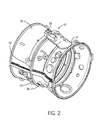
- FIG. 2 is a side view of an embodiment of a portion of gas turbine engine 12 of FIG. 1 of the engine 12.
- a first engine casing section 34 and a second engine casing section 36 are adjacent to one another.
- a casing section may be attached to adjacent sections by a plurality of bolts 38 around the circumference of the casings, shown here as connecting flanges 40 and 42 on casing section 34 and casing section 36, respectively.
- an alignment device 44 discussed in more detail below, may be applied to the two adjacent casings 34 and 36. Generally, the movement may be facilitated by moveable portions of the alignment device 44 that move within limited ranges of motion along certain axes.
- the movement may be facilitated by moving a rod 54 along its axis.
- the alignment device 44 is fixed to one casing section, e.g., casing section 34, but not to the adjacent section, e.g., casing section 36, movement of the rod 54 results in casing section 34 being moved along the axis of the rod.
- the movement of the rod 54 is within a limited range of motion that is dictated by the structure of the alignment device 44.
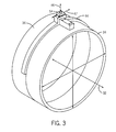
- the first casing section 34 may move relative to casing section 36 along axis 46, the axis substantially in-line with the rod 54, and axis 47, which is substantially perpendicular to the rod 54, as shown in FIG. 3 .
- axes 46 and 47 are defined by the placement of the alignment device on the casing sections 34 and 36.
- axis 46 may be a generally vertical axis while axis 47 may be a generally horizontal axis, whereby both axes are generally perpendicular to the flow path of flow path axis 32 and are perpendicular to each other.
- axis 47 may be a circumferential axis, and may therefore have a slight curvature that follows the circumference of a generic turbine engine casing section.
- the alignment device may allow movement in both directions along axes 46 and 47.
- axis 46 is generally vertical.
- the movement of the rod 54 may pull the casing section 34 up while casing section 36 remains substantially in place.
- the rod 54 could also be pushed down to move casing section 34 down relative to casing section 36.
- the movement of rod 54 in either direction along axis 47 may move casing section 34 in a circumferential direction relative to casing section 36.
- the alignment device 44 may be formed from any suitable materials, including cast metals.
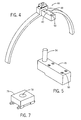
- the alignment device 44 may include a fixed portion 48 configured to be fastened or otherwise mounted to casing section 34.
- the fixed portion 48 may include passageways 50 sized and shaped to receive a series of bolts or other fasteners, such that the bolt heads may be atop an exterior face 49 of the fixed portion.
- a generic turbine engine casing section e.g., casing section 34
- casing section 34 may include predrilled passageways configured to be fastened to the fixed portion 48 at an appropriate location.
- the fixed portion 48 may include a rod 54 that is either integrally formed with the fixed portion 48 or is otherwise attached or connected to the fixed portion 48.
- the fixed portion 48 may include a passageway configured to receive the rod 54, such as a threaded passageway that rod 54 may be screwed into.
- the rod 54 may facilitate movement of casing section 34 along axis 46 to align casing section 34 relative to casing section 36.
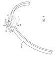
- the alignment device 44 may also include a bridge portion 64, shown in FIG. 6 .
- Bridge portion 64 may be sized and shaped to fit over fixed portion 48 and to rest on casing section 36.
- the bridge portion 64 may include a passageway 66 sized to be larger than rod 54. The amount that the passageway 66 exceeds the diameter of rod 54 may dictate the range of motion of casing section 34 relative to casing section 36 along axis 47.
- the assembly when bridge portion 64 rests atop fixed portion 48, the assembly may include a gap or step 70 between a table 72 and exterior face 49 of the fixed portion 48. The size of step 70 may dictate the range of vertical motion along axis 46 of casing section 34 relative to casing section 36.
- bridge portion 64 may interface with a portion of casing section 36. In embodiments, the bridge portion 64 may at least partially encircle a portion of casing section 36. For example, in embodiments the bridge portion 64 may contact at least about a 30° portion of the circumference of casing section 36, at least about a 45° portion of the circumference of casing section 36, at least about a 90° degree portion of the circumference of casing section 36, or at least about a 120° degree portion of the circumference of casing section 36.
- alignment device 44 may also include a slideable portion 76, shown in perspective view in FIG. 7 .
- the slideable portion 76 may be sized and shaped to rest atop table 72 of bridge portion 64 and may be configured to move along axis 47.
- slideable portion 76 may be attached to bridge portion 64.
- slideable portion 76 may be a separable component from bridge portion 64.
- Slideable portion 76 may include a passageway 78 sized to accommodate rod 54.
- the diameter of passageway 78 may be relatively smaller than the diameter of passageway 66.
- slideable portion 76 may include a slide table 80 that moves along track rail 82 via ball screw 84.
- the motorized assembly 79 may include one or more sensor rails 86 to facilitate control of the rate and position of the movement.
- the motor 88 may provide the power to the assembly 79.
- the motorized assembly 79 may be under the control of a processor-based device.
- the movement of the rod 54 may be facilitated by a hydraulic tensioner or bolt elongation device 90.
- the rod 54 may interface with bolt elongation device 90 to pull fixed portion 48 along axis 46.
- the rod 54 may include a threaded end 92.
- the rod 54 may include a hook, passageway, or other connection point for the bolt elongation device 90. It should be noted that the rod 54 does not extend below fixed portion 48 to engage the second casing section 36.
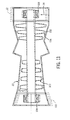
- FIG. 11 is a partial cutaway side view of an exemplary turbine 22.
- the rotating shaft 26 sits on two bearings 108.
- Blades 100 are distributed about the shaft 26 and rotate in the turbine 22. Air that moves past blade tips 102 into the clearance space 106 between a turbine casing (e.g. casing section 36) and the blade tip 102 may decrease the efficiency of the turbine 22. Accordingly, the clearance 106 may be changed by alignment performed on an inlet casing section 110 or an outlet casing section 112. As shown in FIG. 11 , casing section 112 may be moved in a direction 114 relative to the inlet casing section 110.
- casing sections 110 and 112 include bearings 108 on which the shaft 26 sits. Accordingly, in one embodiment, alignment of casing section 110 or 112 may move one or both of the bearings 108 as well. This impacts the alignment of the shaft 26 throughout the turbine 22, which can in turn change the position of the blades 100 and blade tips 102. In other embodiments, such alignment may be also performed on the compressor section 18, which may include blades that rotate about the shaft 26.
Landscapes
- Engineering & Computer Science (AREA)
- Mechanical Engineering (AREA)
- General Engineering & Computer Science (AREA)
- Structures Of Non-Positive Displacement Pumps (AREA)
Abstract
Description
- The subject matter disclosed herein relates to gas turbine engines, and more specifically, to alignment tools for moving and/or aligning sections of gas turbine engines.
- In general, gas turbine engines combust a mixture of compressed air and fuel to produce hot combustion gases. The combustion gases may flow through one or more stages of turbine blades to generate power for a load and/or a compressor. The turbine engine may include several casing sections that are connected to one another in a manner that allows the enclosed turbine blades to rotate. Misalignment of the casing sections may interfere with efficient turning of the turbine blades and efficient flow of air through the engine. During assembly, these sections may be aligned by stacking the sections vertically and fastening them to one another before positioning the turbine engine assembly in a horizontal position for installation, for example by using jacks or hydraulic machinery. During service, an operator may need to access an individual section of the engine. When the section is replaced and/or reinstalled, the realignment of the section to the rest of the engine may be challenging, particularly depending on the immediate environment of the engine.
- In one embodiment, a system includes a first turbine engine casing section; a second turbine engine casing section; and an alignment device. The alignment device includes a fixed portion configured to be fixedly attached to the first turbine engine casing; and a bridge portion configured to interface with the second turbine engine casing section and the fixed portion, wherein the bridge portion defines a first range of motion for the fixed portion along a first axis and a second range of motion for the fixed portion along a second axis when the alignment device is engaged with the first turbine engine casing section and the second turbine engine casing section, and wherein the alignment device is configured to facilitate movement of the first turbine engine casing section relative to the second turbine engine casing section within the first range of motion and the second range of motion.
- In another embodiment, an alignment device includes a fixed portion configured to be fixedly attached to the first turbine engine casing section, wherein the fixed portion comprises a rod; a bridge portion configured to interface with the fixed portion and comprising a passageway sized to accommodate the rod; and a slideable portion configured to move along an axis substantially perpendicular to the rod.
- In yet another embodiment, a system includes: a first turbine engine casing adjacent to a second turbine engine casing. The system also includes a fixed portion configured to be fixedly attached to the first turbine engine casing section, wherein the fixed portion includes a rod; a bridge portion configured to interface with the fixed portion and including a passageway sized to accommodate the rod; and a slideable portion configured to move along an axis substantially perpendicular to the rod, wherein movement of the slideable portion moves the first turbine engine casing relative to the second turbine engine casing.
- Various features, aspects, and advantages of the present invention will become better understood when the following detailed description is read with reference to the accompanying drawings in which like characters represent like parts throughout the drawings, wherein:
-
FIG. 1 is a schematic flow diagram of an embodiment of a gas turbine engine that may employ turbine blade platforms; -
FIG. 2 is a perspective view of an embodiment of adjacent exterior casings of a gas turbine engine with an alignment device applied to the adjacent casings; -
FIG. 3 is perspective view of an embodiment of adjacent exterior casings of a gas turbine engine with an alignment device applied to the adjacent casings and the axes of motion of the alignment device; -
FIG. 4 is perspective view of an embodiment of an alignment device -
FIG. 5 is a perspective view of an embodiment of a fixed portion component of the alignment device shown inFIG. 4 ; -
FIG. 6 is a perspective view of an embodiment of a bridge portion component of the alignment device shown inFIG. 4 ; -
FIG. 7 is a perspective view of an embodiment of a slideable portion component of the alignment device shown inFIG. 4 ; -
FIG. 8 is a perspective view of an embodiment of a slideable motion of a rod structure of an alignment device; -
FIG. 9 is a cutaway perspective view of an embodiment of a slide table of an exemplary slideable portion; -
FIG. 10 is a perspective view of an embodiment of a bolt elongation device affixed to a rod portion to facilitate vertical movement; and -
FIG. 11 is a cutaway side view of an embodiment of a turbine in which turbine blade clearance is aligned relative to the turbine casing. - One or more specific embodiments of the present invention will be described below. In an effort to provide a concise description of these embodiments, all features of an actual implementation may not be described in the specification. It should be appreciated that in the development of any such actual implementation, as in any engineering or design project, numerous implementation-specific decisions must be made to achieve the developers' specific goals, such as compliance with system-related and business-related constraints, which may vary from one implementation to another. Moreover, it should be appreciated that such a development effort might be complex and time consuming, but would nevertheless be a routine undertaking of design, fabrication, and manufacture for those of ordinary skill having the benefit of this disclosure.
- When introducing elements of various embodiments of the present invention, the articles "a," "an," "the," and "said" are intended to mean that there are one or more of the elements. The terms "comprising," "including," and "having" are intended to be inclusive and mean that there may be additional elements other than the listed elements.
- The present disclosure is directed to alignment devices for aligning adjacent casing sections in a gas turbine engine. In the turbine part of the engine, the casing that encloses the rotating components (e.g., the shaft and blades) may be assembled in sections, which allows individual parts of the turbine to be accessed and serviced more easily. After service operations, an operator may reinstall a section of casing and perform an alignment with the adjacent sections. However, if the engine has been assembled in an area without sufficient clearance beneath the engine, hydraulic jacks or other lifts may not be suitable for holding an individual casing section and moving it into place. In addition, during normal operation of the turbine engine, these sections of casing may become slightly misaligned because, for example, the fasteners between the casings may become loose. When such misalignment occurs, the shaft and the blades may not rotate as efficiently and energy may be lost to the environment. Therefore, in accordance with certain embodiments, an alignment device may be applied to adjacent casing sections to allow an operator to perform fine alignment of the casings. The alignment device may be relatively compact in comparison to the scale of the engine, and therefore, may be applied to casing sections that are otherwise difficult to access and maneuver. The alignment device may allow more flexible installation arrangements for gas turbine engines, because alignment may be performed on casing sections that have limited surrounding clearance. Therefore, the alignment device may perform alignment of adjacent casing sections without the use of hydraulic lifts or other holding devices placed underneath the turbine engine.
- The alignment device may be configured to interface with adjacent sections of casing. For example, in one embodiment, the alignment device may include a fixed portion and a bridge portion. When applied to adjacent casing sections, the fixed portion may be fixed on one casing section while not being fixed on the adjacent casing to facilitate relative movement of the adjacent casing sections. In addition, the alignment device may include a bridge or cradle portion that is not fixed on either casing section to provide additional strength and/or stability to the attachment. In an embodiment, the bridge component may define and/or limit one or more ranges of relative motion between the adjacent casing sections. After the alignment device is applied, at least a portion of the fasteners connecting the adjacent casing sections may be loosened and/or removed. The alignment device may be of sufficient strength and may have sufficient load-bearing capacity to bear the weight of the partially or completely unfastened casing sections. After the fasteners have been loosened, fine alignment may be performed by moving adjustable components of the alignment device within their ranges of motion. After the alignment is performed, the fasteners may be reapplied or tightened to lock the adjacent casing sections into place.
-
FIG. 1 is a block diagram of anexemplary system 10 including agas turbine engine 12 that may include casing sections that may be aligned with the alignment tool as provided herein. In certain embodiments, thesystem 10 may include an aircraft, a watercraft, a locomotive, a power generation system, or combinations thereof. The illustratedgas turbine engine 12 includes anair intake section 16, acompressor 18, acombustor section 20, aturbine 22, and anexhaust section 24. Theturbine 22 is drivingly coupled to thecompressor 18 via ashaft 26. The shaft is also drivingly coupled to a load 14, which is positioned at the exhaust end of theturbine engine 12. - As indicated by the arrows, air may enter the
gas turbine engine 12 through theintake section 16 and flow into thecompressor 18, which compresses the air prior to entry into thecombustor section 20. The illustratedcombustor section 20 includes acombustor housing 28 disposed concentrically or annularly about theshaft 26 between thecompressor 18 and theturbine 22. The compressed air from thecompressor 18 enterscombustors 30 where the compressed air may mix and combust with fuel within thecombustors 30 to drive theturbine 22. - From the
combustor section 20, the hot combustion gases flow through theturbine 22, driving thecompressor 18 via theshaft 26. For example, the combustion gases may apply motive forces to turbine rotor blades within theturbine 22 to rotate theshaft 26. After flowing through theturbine 22, the hot combustion gases may exit thegas turbine engine 12 through theexhaust section 24. -
FIG. 2 is a side view of an embodiment of a portion ofgas turbine engine 12 ofFIG. 1 of theengine 12. As depicted, a firstengine casing section 34 and a secondengine casing section 36 are adjacent to one another. Typically, a casing section may be attached to adjacent sections by a plurality ofbolts 38 around the circumference of the casings, shown here as connectingflanges casing section 34 andcasing section 36, respectively. As shown, analignment device 44, discussed in more detail below, may be applied to the twoadjacent casings alignment device 44 that move within limited ranges of motion along certain axes. For example, the movement may be facilitated by moving arod 54 along its axis. Because thealignment device 44 is fixed to one casing section, e.g., casingsection 34, but not to the adjacent section, e.g., casingsection 36, movement of therod 54 results incasing section 34 being moved along the axis of the rod. The movement of therod 54 is within a limited range of motion that is dictated by the structure of thealignment device 44. - More specifically, when the
alignment device 44 is mounted on theadjacent casing sections first casing section 34 may move relative tocasing section 36 alongaxis 46, the axis substantially in-line with therod 54, andaxis 47, which is substantially perpendicular to therod 54, as shown inFIG. 3 . In should be understood thataxes casing sections axis 46 may be a generally vertical axis whileaxis 47 may be a generally horizontal axis, whereby both axes are generally perpendicular to the flow path offlow path axis 32 and are perpendicular to each other. In embodiments,axis 47 may be a circumferential axis, and may therefore have a slight curvature that follows the circumference of a generic turbine engine casing section. In addition, as shown, the alignment device may allow movement in both directions alongaxes alignment device 44 is placed generally on a top or upper portion of an alignment device,axis 46 is generally vertical. In such an embodiment, the movement of therod 54 may pull thecasing section 34 up while casingsection 36 remains substantially in place. Therod 54 could also be pushed down to movecasing section 34 down relative tocasing section 36. The movement ofrod 54 in either direction alongaxis 47 may movecasing section 34 in a circumferential direction relative tocasing section 36. - An
exemplary alignment device 44 is shown in perspective view inFIG. 4 . Thealignment device 44 may be formed from any suitable materials, including cast metals. Thealignment device 44 may include a fixedportion 48 configured to be fastened or otherwise mounted tocasing section 34. As shown inFIG. 4 , the fixedportion 48 may includepassageways 50 sized and shaped to receive a series of bolts or other fasteners, such that the bolt heads may be atop anexterior face 49 of the fixed portion. In embodiments, a generic turbine engine casing section (e.g., casing section 34) may include predrilled passageways configured to be fastened to the fixedportion 48 at an appropriate location. - As shown in more detail in the perspective view of
FIG. 5 , the fixedportion 48 may include arod 54 that is either integrally formed with the fixedportion 48 or is otherwise attached or connected to the fixedportion 48. In embodiments in which therod 54 is not unitary with the fixedportion 48, the fixedportion 48 may include a passageway configured to receive therod 54, such as a threaded passageway thatrod 54 may be screwed into. When the fixedportion 48 is fastened tocasing section 34, therod 54 may facilitate movement ofcasing section 34 alongaxis 46 to aligncasing section 34 relative tocasing section 36. - The
alignment device 44 may also include abridge portion 64, shown inFIG. 6 .Bridge portion 64 may be sized and shaped to fit over fixedportion 48 and to rest oncasing section 36. Thebridge portion 64 may include apassageway 66 sized to be larger thanrod 54. The amount that thepassageway 66 exceeds the diameter ofrod 54 may dictate the range of motion ofcasing section 34 relative tocasing section 36 alongaxis 47. In addition, whenbridge portion 64 rests atop fixedportion 48, the assembly may include a gap or step 70 between a table 72 andexterior face 49 of the fixedportion 48. The size ofstep 70 may dictate the range of vertical motion alongaxis 46 ofcasing section 34 relative tocasing section 36. In embodiments,bridge portion 64 may interface with a portion ofcasing section 36. In embodiments, thebridge portion 64 may at least partially encircle a portion ofcasing section 36. For example, in embodiments thebridge portion 64 may contact at least about a 30° portion of the circumference ofcasing section 36, at least about a 45° portion of the circumference ofcasing section 36, at least about a 90° degree portion of the circumference ofcasing section 36, or at least about a 120° degree portion of the circumference ofcasing section 36. - In embodiments,
alignment device 44 may also include aslideable portion 76, shown in perspective view inFIG. 7 . Theslideable portion 76 may be sized and shaped to rest atop table 72 ofbridge portion 64 and may be configured to move alongaxis 47. In one embodiment,slideable portion 76 may be attached to bridgeportion 64. In another embodiment,slideable portion 76 may be a separable component frombridge portion 64.Slideable portion 76 may include apassageway 78 sized to accommodaterod 54. The diameter ofpassageway 78 may be relatively smaller than the diameter ofpassageway 66. As shown in the perspective view ofFIG. 8 ,rod 54 moves alongaxis 47 whenslideable portion 76 slides relative to table 72. As a result, whenrod 54 moves alongaxis 47,casing section 34, to which fixedportion 48 is attached, also moves relative tocasing section 36. - In one embodiment, the movement of
slideable portion 76 alongaxis 47 may be facilitated by amotorized assembly 79. As shown inFIG. 9 ,slideable portion 76 may include a slide table 80 that moves alongtrack rail 82 viaball screw 84. Themotorized assembly 79 may include one or more sensor rails 86 to facilitate control of the rate and position of the movement. Themotor 88 may provide the power to theassembly 79. In embodiments, themotorized assembly 79 may be under the control of a processor-based device. - In another embodiment, the movement of the
rod 54 may be facilitated by a hydraulic tensioner orbolt elongation device 90. As shown inFIG. 10 , therod 54 may interface withbolt elongation device 90 to pull fixedportion 48 alongaxis 46. As shown, therod 54 may include a threadedend 92. In other embodiments, therod 54 may include a hook, passageway, or other connection point for thebolt elongation device 90. It should be noted that therod 54 does not extend below fixedportion 48 to engage thesecond casing section 36. - In one embodiment, alignment of adjacent casing sections may allow an operator to optimize the clearance of the turbine blade tip relative to the casing.
FIG. 11 is a partial cutaway side view of anexemplary turbine 22. The rotatingshaft 26 sits on twobearings 108.Blades 100 are distributed about theshaft 26 and rotate in theturbine 22. Air that movespast blade tips 102 into theclearance space 106 between a turbine casing (e.g. casing section 36) and theblade tip 102 may decrease the efficiency of theturbine 22. Accordingly, theclearance 106 may be changed by alignment performed on aninlet casing section 110 or anoutlet casing section 112. As shown inFIG. 11 ,casing section 112 may be moved in adirection 114 relative to theinlet casing section 110. Thesecasing sections bearings 108 on which theshaft 26 sits. Accordingly, in one embodiment, alignment ofcasing section bearings 108 as well. This impacts the alignment of theshaft 26 throughout theturbine 22, which can in turn change the position of theblades 100 andblade tips 102. In other embodiments, such alignment may be also performed on thecompressor section 18, which may include blades that rotate about theshaft 26. - This written description uses examples to disclose the invention, including the preferred mode, and to enable any person skilled in the art to practice the invention, including making and using any devices or systems and performing any incorporated methods. The patentable scope of the invention is defined by the claims, and may include other examples that occur to those skilled in the art. Such other examples are intended to be within the scope of the claims if they have structural elements that do not differ from the literal language of the claims, or if they include equivalent structural elements with insubstantial differences from the literal languages of the claims.
- Various aspects and embodiments of the present invention are defined by the following numbered clauses:
- 1. A system, comprising:
- a first turbine engine casing section;
- a second turbine engine casing section; and
- an alignment device comprising:
- a fixed portion configured to be fixedly attached to the first turbine engine casing; and
- a bridge portion configured to interface with the second turbine engine casing section and the fixed portion, wherein the bridge portion defines a first range of motion for the fixed portion along a first axis and a second range of motion for the fixed portion along a second axis when the alignment device is engaged with the first turbine engine casing section and the second turbine engine casing section, and wherein the alignment device is configured to facilitate movement of the first turbine engine casing section relative to the second turbine engine casing section within the first range of motion and the second range of motion.
- 2. The system of clause 1, wherein the fixed portion comprises one or more passageways configured to receive one or more fasteners.
- 3. The system of any preceding clause, wherein the first turbine engine casing section comprises one or more passageways that correspond to the passageways of the fixed portion and are configured to receive the one or more fasteners.
- 4. The system of any preceding clause, wherein the bridge portion is configured to contact at least about a forty-five degree portion of an exterior circumference of the second turbine engine casing section.
- 5. The system of any preceding clause, wherein the bridge portion comprises a passageway configured to define the first range of motion.
- 6. The system of any preceding clause, wherein the alignment device comprises a gap between the bridge portion and the fixed portion configured to define the second range of motion.
- 7. The system of any preceding clause, wherein the first range of motion is circumferential motion of the first turbine engine casing section relative to the second turbine engine casing section.
- 8. The system of any preceding clause, comprising a rotor or rotary blades housed within the first turbine engine casing or the second turbine engine casing.
- 9. An alignment device configured to align a first turbine engine casing section with a second turbine engine casing section, the alignment device comprising:
- a fixed portion configured to be fixedly attached to the first turbine engine casing section, wherein the fixed portion comprises a rod;
- a bridge portion configured to interface with the fixed portion and comprising a passageway sized to accommodate the rod; and
- a slideable portion configured to move along an axis substantially perpendicular to the rod.
- 10. The alignment device of any preceding clause, comprising a hydraulic device coupled to the rod and configured to pull the rod along an axis substantially in-line with the rod.
- 11. The alignment device of any preceding clause, wherein the rod comprises a threaded end.
- 12. The alignment device of any preceding clause, wherein the rod is integrally formed with the fixed portion.
- 13. The alignment device of any preceding clause, wherein slideable portion is coupled to a driver configured to move along the axis substantially perpendicular to the rod.
- 14. The alignment device of any preceding clause, comprising a turbine engine having at least the first turbine engine casing section and the second turbine engine casing section.
- 15. The alignment device of any preceding clause, wherein the first turbine engine casing section is configured to move relative to the second turbine engine casing section when the slideable portion moves along the axis.
- 16. The alignment device of any preceding clause, wherein the rod is configured to move along an axis substantially in-line with the rod, whereby the movement of the rod changes the position the first turbine engine casing section relative to the second turbine engine.
- 17. A system comprising:
- a first turbine engine casing adjacent to a second turbine engine casing;
- a fixed portion configured to be fixedly attached to the first turbine engine casing section, wherein the fixed portion comprises a rod;
- a bridge portion configured to interface with the fixed portion and comprising a passageway sized to accommodate the rod; and
- a slideable portion configured to move along an axis substantially perpendicular to the rod, wherein movement of the slideable portion moves the first turbine engine casing relative to the second turbine engine casing.
- 18. The system of any preceding clause, wherein the first turbine engine casing section comprises one or more passageways that correspond to the passageways of the fixed portion and are configured to receive the one or more fasteners.
- 19. The system of any preceding clause, wherein the bridge portion is configured to contact at least about a forty-five degree portion of an exterior circumference of the second turbine engine casing section.
- 20. The system of any preceding clause, wherein the rod is configured to move along an axis substantially in-line with the rod, whereby the movement of the rod changes the position the first turbine engine casing section relative to the second turbine engine.
Claims (10)
- A system, comprising:a first turbine engine casing section (34);a second turbine engine casing section (36); andan alignment device (44) comprising:a fixed portion (48) configured to be fixedly attached to the first turbine engine casing section (34); anda bridge portion (64) configured to interface with the second turbine engine casing section (36) and the fixed portion (48), wherein the bridge portion (64) defines a first range of motion for the fixed portion (48) along a first axis and a second range of motion for the fixed portion (48) along a second axis when the alignment device (44) is engaged with the first turbine engine casing section (34) and the second turbine engine casing section (36), and wherein the alignment device (44) is configured to facilitate movement of the first turbine engine casing section (34) relative to the second turbine engine casing section (36) within the first range of motion and the second range of motion.
- The system of claim 1, wherein the fixed portion (48) comprises one or more passageways (50) configured to receive one or more fasteners.
- The system of any preceding claim, wherein the first turbine engine casing section (34) comprises one or more passageways that correspond to the passageways of the fixed portion (48) and are configured to receive the one or more fasteners.
- The system of any preceding claim, wherein the bridge portion (64) is configured to contact at least about a forty-five degree portion of an exterior circumference of the second turbine engine casing section (36).
- The system of any preceding claim, wherein the bridge portion (64) comprises a passageway (66) configured to define the first range of motion.
- The system of any preceding claim, wherein the alignment device (44) comprises a gap (70) between the bridge portion (64) and the fixed portion (48) configured to define the second range of motion.
- The system of any preceding claim, wherein the first range of motion is circumferential motion of the first turbine engine casing section (34) relative to the second turbine engine casing section (36).
- The system of any preceding claim, comprising a rotor or rotary blades housed within the first turbine engine casing section (34) or the second turbine engine casing (36).
- An alignment device (44) configured to align a first turbine engine casing section (34) with a second turbine engine casing section (36), the alignment device (44) comprising:a fixed portion (48) configured to be fixedly attached to the first turbine engine casing section (34), wherein the fixed portion (48) comprises a rod (54);a bridge portion (64) configured to interface with the fixed portion (48) and comprising a passageway (66) sized to accommodate the rod (54); anda slideable portion (76) configured to move along an axis substantially perpendicular to the rod (54).
- The alignment device (44) of claim 9, comprising a hydraulic device (90) coupled to the rod (54) and configured to pull the rod (54) along an axis substantially in-line with the rod (54).
Applications Claiming Priority (1)
| Application Number | Priority Date | Filing Date | Title |
|---|---|---|---|
| US12/399,443 US8142150B2 (en) | 2009-03-06 | 2009-03-06 | Alignment device for gas turbine casings |
Publications (3)
| Publication Number | Publication Date |
|---|---|
| EP2226475A2 true EP2226475A2 (en) | 2010-09-08 |
| EP2226475A3 EP2226475A3 (en) | 2014-01-15 |
| EP2226475B1 EP2226475B1 (en) | 2017-01-18 |
Family
ID=42279570
Family Applications (1)
| Application Number | Title | Priority Date | Filing Date |
|---|---|---|---|
| EP10155011.9A Not-in-force EP2226475B1 (en) | 2009-03-06 | 2010-03-01 | Alignment device for gas turbine casings |
Country Status (4)
| Country | Link |
|---|---|
| US (1) | US8142150B2 (en) |
| EP (1) | EP2226475B1 (en) |
| JP (1) | JP5627904B2 (en) |
| CN (1) | CN101865037B (en) |
Cited By (1)
| Publication number | Priority date | Publication date | Assignee | Title |
|---|---|---|---|---|
| EP3404208A1 (en) * | 2017-05-05 | 2018-11-21 | Rolls-Royce Deutschland Ltd & Co KG | Air flow guidance device and method for formation of same |
Families Citing this family (23)
| Publication number | Priority date | Publication date | Assignee | Title |
|---|---|---|---|---|
| US8662834B2 (en) * | 2009-06-30 | 2014-03-04 | General Electric Company | Method for reducing tip rub loading |
| CH703430A1 (en) * | 2010-07-13 | 2012-01-13 | Alstom Technology Ltd | Method for adjusting the rotor position in a gas turbine or steam turbine. |
| US20130015752A1 (en) * | 2011-07-15 | 2013-01-17 | General Electric Company | Rotatable power-plant case section |
| US8689455B2 (en) | 2012-02-29 | 2014-04-08 | Solar Turbines Inc. | Shaft alignment tool |
| JP5881474B2 (en) * | 2012-03-02 | 2016-03-09 | 三菱日立パワーシステムズ株式会社 | Assembly / disassembly jig for gas turbine casing, gas turbine provided with the same, assembly method and disassembly method for gas turbine casing |
| US20130326875A1 (en) * | 2012-06-08 | 2013-12-12 | General Electric Company | Method and apparatus for roll-in and alignment of a casing shell of a gas turbine |
| US8955230B2 (en) | 2012-06-12 | 2015-02-17 | Solar Turbines Inc. | Shaft alignment tools and methods |
| US8997365B2 (en) | 2012-06-12 | 2015-04-07 | Solar Turbines Incorporated | Shaft alignment tools and methods |
| US9200539B2 (en) | 2012-07-12 | 2015-12-01 | General Electric Company | Turbine shell support arm |
| WO2014051663A1 (en) | 2012-09-28 | 2014-04-03 | United Technologies Corporation | Alignment tool for use in a gas turbine engine |
| US8844107B2 (en) | 2012-11-09 | 2014-09-30 | General Electric Company | System for assembling and disassembling a turbine section of a gas turbine |
| FR3008912B1 (en) * | 2013-07-29 | 2017-12-15 | Snecma | TURBOMACHINE CASING AND METHOD OF MANUFACTURE |
| US9458737B2 (en) | 2013-10-04 | 2016-10-04 | Siemens Energy, Inc. | Adjustable bracing apparatus and assembly method for gas turbine exhaust diffuser |
| US9441498B2 (en) * | 2013-10-30 | 2016-09-13 | Siemens Energy, Inc. | Process and tool for aligning a seal housing assembly with a casing of a gas turbine engine |
| US10502059B2 (en) | 2015-02-02 | 2019-12-10 | United Technologies Corporation | Alignment tie rod device and method of utilization |
| US10082042B2 (en) * | 2015-06-22 | 2018-09-25 | United Technologies Corporation | Case coupling and assembly |
| US10125634B2 (en) | 2015-12-10 | 2018-11-13 | General Electric Company | Combustor assembly alignment and securement systems |
| US10584609B2 (en) | 2016-06-22 | 2020-03-10 | Rolls-Royce Corporation | Gas turbine engine frame alignment tool |
| PL3284919T3 (en) * | 2016-08-16 | 2024-12-09 | General Electric Technology Gmbh | Axial flow turbine having a diaphragm split in two halves at a joint plane |
| KR102491290B1 (en) * | 2018-08-17 | 2023-01-27 | 미츠비시 파워 가부시키가이샤 | Position adjustment method and position adjustment jig of arc-shaped member |
| KR102386923B1 (en) * | 2020-03-13 | 2022-04-14 | 두산중공업 주식회사 | Structure for fixing turbine exhaust portion, turbine and gas turbine using the same |
| CN111927580B (en) * | 2020-08-12 | 2023-07-11 | 中国人民解放军第五七一九工厂 | Aeroengine turbine casing alignment structure and installation method |
| JP7299945B2 (en) * | 2021-06-04 | 2023-06-28 | 三菱重工業株式会社 | Turbine casing, gas turbine and alignment method |
Family Cites Families (13)
| Publication number | Priority date | Publication date | Assignee | Title |
|---|---|---|---|---|
| BE487116A (en) * | 1946-07-16 | |||
| US4195828A (en) * | 1979-01-19 | 1980-04-01 | Peterson Donald M | Boiler tube welding clamp |
| US5094435A (en) * | 1990-11-09 | 1992-03-10 | Cogsdill Tool Products, Inc. | Flange alignment tool and method |
| US5228181A (en) * | 1991-08-26 | 1993-07-20 | Ingle Michael D | Flange aligning device |
| US5560091A (en) * | 1994-05-26 | 1996-10-01 | Labit, Jr.; Sexon J. | Apparatus for aligning pipe flanges |
| US5513547A (en) | 1995-01-06 | 1996-05-07 | Westinghouse Electric Corporation | Combustion turbine alignment method and apparatus |
| US5737913A (en) * | 1996-10-18 | 1998-04-14 | The United States Of America As Represented By The Secretary Of The Air Force | Self-aligning quick release engine case assembly |
| JP4363799B2 (en) * | 2001-06-08 | 2009-11-11 | 株式会社東芝 | Turbine assembly transport stand, turbine assembly method using the stand, and transport method |
| US6839979B1 (en) | 2003-08-25 | 2005-01-11 | General Electric Company | Top mounted turbine casing alignment tool with multi-axis maneuverability |
| US8079773B2 (en) * | 2005-10-18 | 2011-12-20 | General Electric Company | Methods and apparatus for assembling composite structures |
| CN200954579Y (en) * | 2006-09-29 | 2007-10-03 | 邯郸钢铁股份有限公司 | Pipeline butt-jointing corrector |
| JP4865508B2 (en) * | 2006-11-01 | 2012-02-01 | 三菱重工業株式会社 | Alignment mechanism |
| CN101314204B (en) * | 2008-06-23 | 2010-08-18 | 杜江 | Positioning method for trunnion shaft assembly phase point |
-
2009
- 2009-03-06 US US12/399,443 patent/US8142150B2/en not_active Expired - Fee Related
-
2010
- 2010-03-01 EP EP10155011.9A patent/EP2226475B1/en not_active Not-in-force
- 2010-03-03 JP JP2010046027A patent/JP5627904B2/en not_active Expired - Fee Related
- 2010-03-08 CN CN201010139490.5A patent/CN101865037B/en not_active Expired - Fee Related
Non-Patent Citations (1)
| Title |
|---|
| None |
Cited By (2)
| Publication number | Priority date | Publication date | Assignee | Title |
|---|---|---|---|---|
| EP3404208A1 (en) * | 2017-05-05 | 2018-11-21 | Rolls-Royce Deutschland Ltd & Co KG | Air flow guidance device and method for formation of same |
| US10954885B2 (en) | 2017-05-05 | 2021-03-23 | Rolls-Royce Deutschland Ltd & Co Kg | Flow guiding device and method for forming a flow guiding device |
Also Published As
| Publication number | Publication date |
|---|---|
| CN101865037B (en) | 2014-12-03 |
| JP2010209910A (en) | 2010-09-24 |
| CN101865037A (en) | 2010-10-20 |
| EP2226475A3 (en) | 2014-01-15 |
| US8142150B2 (en) | 2012-03-27 |
| US20100226770A1 (en) | 2010-09-09 |
| JP5627904B2 (en) | 2014-11-19 |
| EP2226475B1 (en) | 2017-01-18 |
Similar Documents
| Publication | Publication Date | Title |
|---|---|---|
| US8142150B2 (en) | Alignment device for gas turbine casings | |
| US8713776B2 (en) | System and tool for installing combustion liners | |
| US10920621B2 (en) | Horizontal engine build stand | |
| JP7034665B2 (en) | Installing or removing turbine blades at the base of the turbine blades | |
| US9896973B2 (en) | Assembly tool for exhaust turbochargers | |
| US10724385B2 (en) | Installation or removal of turbine blade at turbine blade base | |
| EP2551474B1 (en) | Method for supporting a shaft inside a turbine | |
| EP2557277A2 (en) | Method and Apparatus to Facilitate Turbine Casing Assembly | |
| US10519810B2 (en) | Manipulation of turbomachine combustors | |
| US11732613B2 (en) | Apparatus for removal or installation of turbine blade | |
| EP2811123A1 (en) | Apparatus for pivoting an upper portion of a turbine shell | |
| JP7233882B2 (en) | LOAD COUPLING INSTALLATION DEVICE AND METHOD FOR INSTALLING LOAD COUPLING IN TURBINE SYSTEM | |
| EP3293359A2 (en) | Manipulation of turbomachine combustors | |
| KR20220082889A (en) | Installation/removal apparatus, and method for one or more rotor blocks of a turbocharger assembly | |
| JP2024505372A (en) | Equipment for removing or installing turbine blades | |
| US20180087383A1 (en) | Fixture for restraining a turbine wheel | |
| WO2018063667A1 (en) | Fixture for restraining a turbine wheel and corresponding method |
Legal Events
| Date | Code | Title | Description |
|---|---|---|---|
| PUAI | Public reference made under article 153(3) epc to a published international application that has entered the european phase |
Free format text: ORIGINAL CODE: 0009012 |
|
| AK | Designated contracting states |
Kind code of ref document: A2 Designated state(s): AT BE BG CH CY CZ DE DK EE ES FI FR GB GR HR HU IE IS IT LI LT LU LV MC MK MT NL NO PL PT RO SE SI SK SM TR |
|
| AX | Request for extension of the european patent |
Extension state: AL BA ME RS |
|
| PUAL | Search report despatched |
Free format text: ORIGINAL CODE: 0009013 |
|
| AK | Designated contracting states |
Kind code of ref document: A3 Designated state(s): AT BE BG CH CY CZ DE DK EE ES FI FR GB GR HR HU IE IS IT LI LT LU LV MC MK MT NL NO PL PT RO SE SI SK SM TR |
|
| AX | Request for extension of the european patent |
Extension state: AL BA ME RS |
|
| RIC1 | Information provided on ipc code assigned before grant |
Ipc: F01D 25/24 20060101AFI20131209BHEP |
|
| 17P | Request for examination filed |
Effective date: 20140715 |
|
| RBV | Designated contracting states (corrected) |
Designated state(s): AT BE BG CH CY CZ DE DK EE ES FI FR GB GR HR HU IE IS IT LI LT LU LV MC MK MT NL NO PL PT RO SE SI SK SM TR |
|
| GRAP | Despatch of communication of intention to grant a patent |
Free format text: ORIGINAL CODE: EPIDOSNIGR1 |
|
| INTG | Intention to grant announced |
Effective date: 20160419 |
|
| INTC | Intention to grant announced (deleted) | ||
| GRAR | Information related to intention to grant a patent recorded |
Free format text: ORIGINAL CODE: EPIDOSNIGR71 |
|
| GRAS | Grant fee paid |
Free format text: ORIGINAL CODE: EPIDOSNIGR3 |
|
| INTG | Intention to grant announced |
Effective date: 20161109 |
|
| GRAA | (expected) grant |
Free format text: ORIGINAL CODE: 0009210 |
|
| AK | Designated contracting states |
Kind code of ref document: B1 Designated state(s): AT BE BG CH CY CZ DE DK EE ES FI FR GB GR HR HU IE IS IT LI LT LU LV MC MK MT NL NO PL PT RO SE SI SK SM TR |
|
| REG | Reference to a national code |
Ref country code: GB Ref legal event code: FG4D |
|
| REG | Reference to a national code |
Ref country code: CH Ref legal event code: EP |
|
| REG | Reference to a national code |
Ref country code: AT Ref legal event code: REF Ref document number: 863047 Country of ref document: AT Kind code of ref document: T Effective date: 20170215 |
|
| REG | Reference to a national code |
Ref country code: IE Ref legal event code: FG4D |
|
| REG | Reference to a national code |
Ref country code: DE Ref legal event code: R096 Ref document number: 602010039633 Country of ref document: DE |
|
| PGFP | Annual fee paid to national office [announced via postgrant information from national office to epo] |
Ref country code: CH Payment date: 20170327 Year of fee payment: 8 |
|
| REG | Reference to a national code |
Ref country code: NL Ref legal event code: MP Effective date: 20170118 |
|
| REG | Reference to a national code |
Ref country code: LT Ref legal event code: MG4D |
|
| PGFP | Annual fee paid to national office [announced via postgrant information from national office to epo] |
Ref country code: GB Payment date: 20170327 Year of fee payment: 8 |
|
| REG | Reference to a national code |
Ref country code: AT Ref legal event code: MK05 Ref document number: 863047 Country of ref document: AT Kind code of ref document: T Effective date: 20170118 |
|
| PG25 | Lapsed in a contracting state [announced via postgrant information from national office to epo] |
Ref country code: NL Free format text: LAPSE BECAUSE OF FAILURE TO SUBMIT A TRANSLATION OF THE DESCRIPTION OR TO PAY THE FEE WITHIN THE PRESCRIBED TIME-LIMIT Effective date: 20170118 |
|
| PGFP | Annual fee paid to national office [announced via postgrant information from national office to epo] |
Ref country code: IT Payment date: 20170324 Year of fee payment: 8 |
|
| PG25 | Lapsed in a contracting state [announced via postgrant information from national office to epo] |
Ref country code: NO Free format text: LAPSE BECAUSE OF FAILURE TO SUBMIT A TRANSLATION OF THE DESCRIPTION OR TO PAY THE FEE WITHIN THE PRESCRIBED TIME-LIMIT Effective date: 20170418 Ref country code: LT Free format text: LAPSE BECAUSE OF FAILURE TO SUBMIT A TRANSLATION OF THE DESCRIPTION OR TO PAY THE FEE WITHIN THE PRESCRIBED TIME-LIMIT Effective date: 20170118 Ref country code: IS Free format text: LAPSE BECAUSE OF FAILURE TO SUBMIT A TRANSLATION OF THE DESCRIPTION OR TO PAY THE FEE WITHIN THE PRESCRIBED TIME-LIMIT Effective date: 20170518 Ref country code: HR Free format text: LAPSE BECAUSE OF FAILURE TO SUBMIT A TRANSLATION OF THE DESCRIPTION OR TO PAY THE FEE WITHIN THE PRESCRIBED TIME-LIMIT Effective date: 20170118 Ref country code: GR Free format text: LAPSE BECAUSE OF FAILURE TO SUBMIT A TRANSLATION OF THE DESCRIPTION OR TO PAY THE FEE WITHIN THE PRESCRIBED TIME-LIMIT Effective date: 20170419 Ref country code: FI Free format text: LAPSE BECAUSE OF FAILURE TO SUBMIT A TRANSLATION OF THE DESCRIPTION OR TO PAY THE FEE WITHIN THE PRESCRIBED TIME-LIMIT Effective date: 20170118 |
|
| PGFP | Annual fee paid to national office [announced via postgrant information from national office to epo] |
Ref country code: DE Payment date: 20170329 Year of fee payment: 8 |
|
| PG25 | Lapsed in a contracting state [announced via postgrant information from national office to epo] |
Ref country code: PL Free format text: LAPSE BECAUSE OF FAILURE TO SUBMIT A TRANSLATION OF THE DESCRIPTION OR TO PAY THE FEE WITHIN THE PRESCRIBED TIME-LIMIT Effective date: 20170118 Ref country code: AT Free format text: LAPSE BECAUSE OF FAILURE TO SUBMIT A TRANSLATION OF THE DESCRIPTION OR TO PAY THE FEE WITHIN THE PRESCRIBED TIME-LIMIT Effective date: 20170118 Ref country code: BG Free format text: LAPSE BECAUSE OF FAILURE TO SUBMIT A TRANSLATION OF THE DESCRIPTION OR TO PAY THE FEE WITHIN THE PRESCRIBED TIME-LIMIT Effective date: 20170418 Ref country code: SE Free format text: LAPSE BECAUSE OF FAILURE TO SUBMIT A TRANSLATION OF THE DESCRIPTION OR TO PAY THE FEE WITHIN THE PRESCRIBED TIME-LIMIT Effective date: 20170118 Ref country code: LV Free format text: LAPSE BECAUSE OF FAILURE TO SUBMIT A TRANSLATION OF THE DESCRIPTION OR TO PAY THE FEE WITHIN THE PRESCRIBED TIME-LIMIT Effective date: 20170118 Ref country code: ES Free format text: LAPSE BECAUSE OF FAILURE TO SUBMIT A TRANSLATION OF THE DESCRIPTION OR TO PAY THE FEE WITHIN THE PRESCRIBED TIME-LIMIT Effective date: 20170118 Ref country code: PT Free format text: LAPSE BECAUSE OF FAILURE TO SUBMIT A TRANSLATION OF THE DESCRIPTION OR TO PAY THE FEE WITHIN THE PRESCRIBED TIME-LIMIT Effective date: 20170518 |
|
| REG | Reference to a national code |
Ref country code: DE Ref legal event code: R097 Ref document number: 602010039633 Country of ref document: DE |
|
| PG25 | Lapsed in a contracting state [announced via postgrant information from national office to epo] |
Ref country code: RO Free format text: LAPSE BECAUSE OF FAILURE TO SUBMIT A TRANSLATION OF THE DESCRIPTION OR TO PAY THE FEE WITHIN THE PRESCRIBED TIME-LIMIT Effective date: 20170118 Ref country code: SK Free format text: LAPSE BECAUSE OF FAILURE TO SUBMIT A TRANSLATION OF THE DESCRIPTION OR TO PAY THE FEE WITHIN THE PRESCRIBED TIME-LIMIT Effective date: 20170118 Ref country code: CZ Free format text: LAPSE BECAUSE OF FAILURE TO SUBMIT A TRANSLATION OF THE DESCRIPTION OR TO PAY THE FEE WITHIN THE PRESCRIBED TIME-LIMIT Effective date: 20170118 Ref country code: EE Free format text: LAPSE BECAUSE OF FAILURE TO SUBMIT A TRANSLATION OF THE DESCRIPTION OR TO PAY THE FEE WITHIN THE PRESCRIBED TIME-LIMIT Effective date: 20170118 |
|
| PLBE | No opposition filed within time limit |
Free format text: ORIGINAL CODE: 0009261 |
|
| STAA | Information on the status of an ep patent application or granted ep patent |
Free format text: STATUS: NO OPPOSITION FILED WITHIN TIME LIMIT |
|
| PG25 | Lapsed in a contracting state [announced via postgrant information from national office to epo] |
Ref country code: MC Free format text: LAPSE BECAUSE OF FAILURE TO SUBMIT A TRANSLATION OF THE DESCRIPTION OR TO PAY THE FEE WITHIN THE PRESCRIBED TIME-LIMIT Effective date: 20170118 Ref country code: SM Free format text: LAPSE BECAUSE OF FAILURE TO SUBMIT A TRANSLATION OF THE DESCRIPTION OR TO PAY THE FEE WITHIN THE PRESCRIBED TIME-LIMIT Effective date: 20170118 Ref country code: DK Free format text: LAPSE BECAUSE OF FAILURE TO SUBMIT A TRANSLATION OF THE DESCRIPTION OR TO PAY THE FEE WITHIN THE PRESCRIBED TIME-LIMIT Effective date: 20170118 |
|
| 26N | No opposition filed |
Effective date: 20171019 |
|
| REG | Reference to a national code |
Ref country code: IE Ref legal event code: MM4A |
|
| REG | Reference to a national code |
Ref country code: FR Ref legal event code: ST Effective date: 20171130 |
|
| PG25 | Lapsed in a contracting state [announced via postgrant information from national office to epo] |
Ref country code: LU Free format text: LAPSE BECAUSE OF NON-PAYMENT OF DUE FEES Effective date: 20170301 Ref country code: FR Free format text: LAPSE BECAUSE OF NON-PAYMENT OF DUE FEES Effective date: 20170331 |
|
| PG25 | Lapsed in a contracting state [announced via postgrant information from national office to epo] |
Ref country code: IE Free format text: LAPSE BECAUSE OF NON-PAYMENT OF DUE FEES Effective date: 20170301 Ref country code: SI Free format text: LAPSE BECAUSE OF FAILURE TO SUBMIT A TRANSLATION OF THE DESCRIPTION OR TO PAY THE FEE WITHIN THE PRESCRIBED TIME-LIMIT Effective date: 20170118 |
|
| REG | Reference to a national code |
Ref country code: BE Ref legal event code: MM Effective date: 20170331 |
|
| PG25 | Lapsed in a contracting state [announced via postgrant information from national office to epo] |
Ref country code: BE Free format text: LAPSE BECAUSE OF NON-PAYMENT OF DUE FEES Effective date: 20170331 |
|
| PG25 | Lapsed in a contracting state [announced via postgrant information from national office to epo] |
Ref country code: MT Free format text: LAPSE BECAUSE OF NON-PAYMENT OF DUE FEES Effective date: 20170301 |
|
| REG | Reference to a national code |
Ref country code: DE Ref legal event code: R119 Ref document number: 602010039633 Country of ref document: DE |
|
| REG | Reference to a national code |
Ref country code: CH Ref legal event code: PL |
|
| GBPC | Gb: european patent ceased through non-payment of renewal fee |
Effective date: 20180301 |
|
| PG25 | Lapsed in a contracting state [announced via postgrant information from national office to epo] |
Ref country code: DE Free format text: LAPSE BECAUSE OF NON-PAYMENT OF DUE FEES Effective date: 20181002 |
|
| PG25 | Lapsed in a contracting state [announced via postgrant information from national office to epo] |
Ref country code: IT Free format text: LAPSE BECAUSE OF NON-PAYMENT OF DUE FEES Effective date: 20180301 Ref country code: GB Free format text: LAPSE BECAUSE OF NON-PAYMENT OF DUE FEES Effective date: 20180301 Ref country code: LI Free format text: LAPSE BECAUSE OF NON-PAYMENT OF DUE FEES Effective date: 20180331 Ref country code: CH Free format text: LAPSE BECAUSE OF NON-PAYMENT OF DUE FEES Effective date: 20180331 |
|
| PG25 | Lapsed in a contracting state [announced via postgrant information from national office to epo] |
Ref country code: HU Free format text: LAPSE BECAUSE OF FAILURE TO SUBMIT A TRANSLATION OF THE DESCRIPTION OR TO PAY THE FEE WITHIN THE PRESCRIBED TIME-LIMIT; INVALID AB INITIO Effective date: 20100301 |
|
| PG25 | Lapsed in a contracting state [announced via postgrant information from national office to epo] |
Ref country code: CY Free format text: LAPSE BECAUSE OF NON-PAYMENT OF DUE FEES Effective date: 20170118 |
|
| PG25 | Lapsed in a contracting state [announced via postgrant information from national office to epo] |
Ref country code: MK Free format text: LAPSE BECAUSE OF FAILURE TO SUBMIT A TRANSLATION OF THE DESCRIPTION OR TO PAY THE FEE WITHIN THE PRESCRIBED TIME-LIMIT Effective date: 20170118 |
|
| PG25 | Lapsed in a contracting state [announced via postgrant information from national office to epo] |
Ref country code: TR Free format text: LAPSE BECAUSE OF FAILURE TO SUBMIT A TRANSLATION OF THE DESCRIPTION OR TO PAY THE FEE WITHIN THE PRESCRIBED TIME-LIMIT Effective date: 20170118 |