EP2226241A1 - Motorcycle including vehicle registration plate at front thereof - Google Patents
Motorcycle including vehicle registration plate at front thereof Download PDFInfo
- Publication number
- EP2226241A1 EP2226241A1 EP10154804A EP10154804A EP2226241A1 EP 2226241 A1 EP2226241 A1 EP 2226241A1 EP 10154804 A EP10154804 A EP 10154804A EP 10154804 A EP10154804 A EP 10154804A EP 2226241 A1 EP2226241 A1 EP 2226241A1
- Authority
- EP
- European Patent Office
- Prior art keywords
- meter
- motorcycle
- headlight
- unit
- vehicle registration
- Prior art date
- Legal status (The legal status is an assumption and is not a legal conclusion. Google has not performed a legal analysis and makes no representation as to the accuracy of the status listed.)
- Granted
Links
Images










Classifications
-
- B—PERFORMING OPERATIONS; TRANSPORTING
- B62—LAND VEHICLES FOR TRAVELLING OTHERWISE THAN ON RAILS
- B62J—CYCLE SADDLES OR SEATS; AUXILIARY DEVICES OR ACCESSORIES SPECIALLY ADAPTED TO CYCLES AND NOT OTHERWISE PROVIDED FOR, e.g. ARTICLE CARRIERS OR CYCLE PROTECTORS
- B62J17/00—Weather guards for riders; Fairings or stream-lining parts not otherwise provided for
- B62J17/02—Weather guards for riders; Fairings or stream-lining parts not otherwise provided for shielding only the rider's front
- B62J17/04—Windscreens
-
- B—PERFORMING OPERATIONS; TRANSPORTING
- B62—LAND VEHICLES FOR TRAVELLING OTHERWISE THAN ON RAILS
- B62J—CYCLE SADDLES OR SEATS; AUXILIARY DEVICES OR ACCESSORIES SPECIALLY ADAPTED TO CYCLES AND NOT OTHERWISE PROVIDED FOR, e.g. ARTICLE CARRIERS OR CYCLE PROTECTORS
- B62J50/00—Arrangements specially adapted for use on cycles not provided for in main groups B62J1/00 - B62J45/00
- B62J50/20—Information-providing devices
- B62J50/25—Information-providing devices intended to provide information to other road users, e.g. signs or flags
- B62J50/26—Number plates
Definitions
- the present invention relates to a motorcycle including a vehicle registration plate provided at the front of the motorcycle, and more specifically to an improvement to the position of a vehicle registration plate.
- JP 6-298144 A discloses a motorcycle including a vehicle registration plate at the front of the motorcycle.
- the vehicle registration plate is also generally called a "number plate” or “license plate.”
- the upper end of a front fork that supports a front wheel is coupled to a head pipe through a bottom bridge and a top bridge.
- the front of the head pipe is covered with a front cowling.
- a headlight and a meter such as a speed meter are provided in the front cowling.
- a rod is extended forward at the front of the bottom bridge and a plate stage for a front number is provided at the tip end of the rod (see paragraph [0012] and Fig. 3 ).
- a motorcycle according to the present invention includes a head pipe, a headlight unit, a meter unit, a meter visor, and a vehicle registration plate.
- the headlight unit is provided in front of the head pipe and includes a headlight.
- the meter unit is provided above the head pipe and includes a meter panel.
- the meter visor is provided in front of the meter unit.
- the vehicle registration plate is attached on the meter visor.
- the headlight unit and the meter unit can be positioned near the center of gravity of the motorcycle while preventing the vehicle registration plate provided at the front of the motorcycle from coming within sight of the rider..
- a motorcycle 1 includes a body frame 2, a front wheel 3, a rear wheel 4, an engine 5, a front fork 6, a handle 7, a rear arm 8, a fuel tank 9, and a seat 10.
- the front wheel 3 and the rear wheel 4 are supported by the body frame 2.
- the engine 5 is supported by the body frame 2 and provided between the front wheel 3 and the rear wheel 4.
- the motorcycle 1 further includes a head pipe 2a.
- the head pipe 2a is formed at the front end of the body frame 2.
- the front fork 6 is supported rotatably at the head pipe 2a.
- the front fork 6 includes outer tubes 6a and inner tubes 6b.
- the front wheel 3 is supported rotatably at the lower ends of the outer tubes 6a.
- the two inner tubes 6b on the right and left are coupled by an upper bracket 6c and a lower bracket 6d.
- a handle 7 is attached to the upper bracket 6c through handle crowns 6e shown in Fig. 3 . Therefore, the handle 7 is supported so that it can steer rightward or leftward around the steering shaft of the front fork 6.
- the rear arm 8 is swingably supported upward or downward around the rear arm bracket 2b of the body frame 2.
- the rear wheel 4 is supported rotatably at the rear end of the rear arm 8.
- the engine 5 is for example a water-cooling type, four-cycle single cylinder engine.
- the engine 5 is supported at the main frame (not shown) and the rear arm bracket 2b of the body frame 2.
- the fuel tank 9 is provided above the engine 5.
- the seat 10 is provided behind the fuel tank 9.
- the motorcycle 1 further includes a meter unit (also referred to as a "meter assembly”) 11, a headlight unit (also referred to as a “headlight assembly”) 12, a vehicle registration plate 13 (also referred to as a "number plate” or “license plate”) 13, a meter visor 14, and winkers 21.
- a meter unit also referred to as a "meter assembly”
- a headlight unit also referred to as a “headlight assembly”
- vehicle registration plate 13 also referred to as a "number plate” or “license plate”
- winkers 21 winkers
- the meter unit 11 is provided above and in front of the head pipe 2a.
- the headlight unit 12 is provided in front of the head pipe 2a. More specifically, the headlight unit 12 is provided under the meter unit 11.
- the meter visor 14 is provided in front of the meter unit 12.
- the vehicle registration plate 13 is attached above the meter visor 14. More specifically, the vehicle registration plate 13 is provided in front of the meter unit 11 and above the headlight unit 12.
- the meter visor 14 is provided between the meter unit 11 and the vehicle registration plate 13.
- the headlight unit 12 includes a headlight 18, right and left side covers 19, and a top cover 20.
- the headlight 18 is provided in the center of the headlight unit 12.
- the left side cover 19 is provided on the left side of the headlight unit 12 and extends to the vicinity of the upper end of the front fork 6 from the left edge of the headlight 18.
- the right side cover 19 is formed symmetrically to the left side cover 19 with respect to the central line C of the motorcycle.
- the top cover 20 is provided on the upper side of the headlight unit 12 and extends to the vicinity of the back surface of the meter unit 11 from the upper edge of the headlight 18.
- the upper edge of the left side cover 19 is connected to the left edge of the top cover 20.
- the upper edge of the right side cover 19 is connected to the right edge of the top cover 20.
- the left side cover 19 has two countersink holes 19a.
- the side cover 19 also has an attachment hole 19d for the left winker 21.
- the right side cover 19 has two countersink holes (not shown) and an attachment hole (not shown) for the right winker 21.
- a bolt 19b is laterally inserted into the countersink hole 19a and screwed to the light case 18h ( Fig. 11 ) of the headlight 18 that will be described. In this way, the side cover 19 is attached to the headlight 18.
- the top cover 20 has a central attachment member 20a and a pair of right and left attachment members 20b as shown in Figs. 9 and 10 .
- the rear end 19' of the side cover 19 is provided above the lower end 2a' of the head pipe 2a when viewed from a lateral side of the motorcycle. Therefore, the headlight unit 12 may be provided as near as possible to the head pipe 2a.
- the top cover 20 has downward recesses 20d.
- the recesses 20d are formed symmetrically with respect to the central line C of the motorcycle.
- the headlight 18 includes a light case 18h, a transparent cover 18f, and a light bulb 181.
- the transparent cover 18f is provided to cover the front opening of the light case 18h.
- the light bulb 181 is a light source and provided in the light case 18h.
- the periphery of the light bulb 181 at the inner surface of the light case 18h has a reflection surface 18i.
- the light bulb 181 is provided in the center in the widthwise direction of the motorcycle, in other words, on the central line C of the motorcycle.
- a central support member 18d is formed above the light case 18h.
- the central attachment member 20a of the top cover 20 shown in Figs. 9 and 10 is screwed to the central support member 18d of the light case 18h by a bolt 20c.
- the right and left attachment members 20b of the top cover 20 shown in Figs. 9 and 10 are similarly screwed to the right and left support members of the light case 18h by bolts. In this way, the top cover 20 is attached to the headlight 18.
- the meter unit 11 is attached to the front fork 6.
- the rear end 11' of the meter unit 11 is positioned substantially immediately above the lower end 2a' of the head pipe 2a. Therefore, the meter unit 11 may be provided as near as possible to the head pipe 2a.
- the meter unit 11 includes a meter case 11a and a meter panel 11b.
- the meter panel 11b is provided in the meter case 11a.
- the meter panel 11b stores meters such as a speed meter 11c, an odometer 11d, and a tachometer 11e.
- the meter visor 14 is provided above the top cover 20 of the headlight unit 12.
- the meter visor 14 is curved to surround the front portion 11" of the meter unit 11.
- the meter visor 14 overlaps the front portion 11" of the meter unit 11 when viewed from a lateral side of the motorcycle.
- the lower portion 14c of the meter visor 14 is positioned in front of the vehicle registration plate 13.
- the meter visor 14 when viewed in the orthogonal direction VII to the meter panel 11b, the meter visor 14 overlaps the vehicle registration plate 13 in the center of the motorcycle widthwise direction as shown in Fig. 12 .
- the central portion 13' of the vehicle registration plate 13 is shielded by the central portion 14' of the meter visor 14.
- the size L2 of the meter visor 14 in the motorcycle widthwise direction is equal to or longer than the size L1 of the vehicle registration plate 13.
- the meter visor 14 prevents sunlight from lowering the visibility of the meter unit 11 and light from the headlight 18 from being reflected by the back surface of the vehicle registration plate 13 to get into the rider's eyes.
- the meter visor 14 when viewed from a lateral side of the motorcycle, the meter visor 14 is provided above the side cover 19. Therefore, the meter visor 14 may be provided as near as possible to the head pipe 2a. As shown in Fig. 5 , the lower part 14c of the meter visor 14 overlaps the recesses 20d of the top cover 20 when viewed from the front of the motorcycle. The lowermost end 14c' of the meter visor 14 is provided on the central line C of the motorcycle. Therefore, the meter visor 14 may be provided as near as possible to the meter unit 11.
- the meter visor 14 has two attachment holes 14b each in the left part and the right part.
- the meter visor 14 is provided between the meter unit 11 and the vehicle registration plate 13 and above the headlight 18.
- the vehicle registration plate 13 is a thin rectangular plate.
- the vehicle registration plate 13 has longer sides provided along the widthwise direction of the motorcycle and shorter sides provided substantially along the vertical direction V As shown in Fig. 4 , the vehicle registration plate 13 is provided above the side cover 19 when viewed from a lateral side of the motorcycle.
- the back surface of the vehicle registration plate 13 may be coated with black plating in order to reduce the reflection of light from the headlight 18.
- the front edge 18f' (positioned on the center line C in the motorcycle widthwise direction in Fig. 5 ) of the transparent cover 18f of the headlight 18 is inclined at least at an angle ⁇ 1 with respect to the vertical line V
- the vehicle registration plate 13 is inclined backward at an angle ⁇ 2 with respect to the vertical line V
- the angle ⁇ 2 is smaller than the angle ⁇ 1. More specifically, the vehicle registration plate 13 is provided substantially in the vertical direction.
- the vehicle registration plate 13 when viewed from a lateral side of the motorcycle, the vehicle registration plate 13 is provided above the side cover 19. Therefore, the vehicle registration plate 13 may be provided as near as possible to the head pipe 2a.
- the motorcycle 1 further includes a headlight stay 16 and a meter bracket 15 shown in Figs. 15 to 17 .
- the headlight stay 16 is a component used to attach the headlight unit 12 to the front fork 6.
- the headlight stay 16 includes a pair of right and left round rods 16a and a coupling plate 16b.
- the round rods 16a extend in the vertical direction.
- the coupling plate 16b is fixed at the lower ends of the round rods 16a.
- the connecting rod 15e of the meter bracket 15 that will be described is welded to the upper ends of the round rods 16a.
- the headlight stay 16 and the meter bracket 15 have substantially a rectangular shape when viewed from the front.
- the round rods 16a have their upper ends bent backward to form engagement portions 16c.
- the lower surface of the upper bracket 6c of the front fork 6 has an engagement recess 6f.
- the engagement portion 16c is secured to the engagement recess 6f through a damper 17.
- the coupling plate 16b is fixed to the lower bracket 6d of the front fork 6 by a bolt 16d. In this way, the headlight stay 16 is attached to the front fork 6.
- the headlight stay 16 further includes a pair of right and left support members 16e.
- attachment members 18a are provided in the right and left parts of the headlight 18.
- a bolt 16f is inserted laterally into the attachment hole of the attachment member 18a and screwed to the support member 16e of the headlight stay 16.
- the headlight stay 16 further includes a pair of right and left support members 16g.
- an adjuster 18b is formed in the left part of the bottom of the headlight 18.
- the adjuster 18b is attached to the support member 16g of the headlight stay 16 by a bolt 16h.
- the bolt 16h is inserted laterally in an elongate hole formed in the adjuster 18b and screwed to the support member 16g of the headlight stay 16.
- the entire headlight unit 12 can be rotated around the bolt 16f. In this way, the optical axis of the headlight 18 can be adjusted.
- the meter bracket 15 is a component used to attach the meter unit 11 to the front fork 6.
- the meter bracket 15 includes a front side 15a and a pair of right and left sides 15b.
- the meter bracket 15 is made of a sheet metal and substantially C-shaped when viewed in a plan view.
- the meter bracket 15 further includes a pair of right and left connecting rods 15e.
- the connecting rods 15e are welded to the upper ends of the round rods 16a of the headlight stay 16, so that the meter bracket 15 is coupled to the headlight stay 16.
- attachment holes 15c are formed at the central part of the front side 15a and the rear ends of the sides 15b.
- a bolt 15d is inserted into the attachment hole 15c from below and fastened to the bottom of the meter case 11a. In this way, the meter unit 11 is attached to the meter bracket 15. Therefore, the meter unit 11 is attached to the front fork 6 through the meter bracket 15 and the headlight stay 16.
- the motorcycle 1 further includes a visor bracket 23 shown in Figs. 19 and 20 .
- the visor bracket 23 is a component used to attach the meter visor 14 to the meter bracket 15.
- the visor bracket 23 includes a pair of right and left support members 23a, a pair of right and left coupling members 23b, and a coupling member 23c used to couple them.
- the support members 23a each have two collars 23d used to attach the vehicle registration plate 13 and the meter visor 14.
- the coupling members 23b each have an attachment hole 23f.
- a bolt 23e is inserted into the attachment hole 23f of the visor bracket 23 from below and screwed to the screw hole 15f of the bracket 15. In this way, the visor bracket 23 is attached to the meter bracket 15.
- the motorcycle 1 further includes a plate bracket 22 as shown in Figs. 21 and 22 .
- the plate bracket 22 is a component used to attach the vehicle registration plate 13 to the meter visor 14.
- the plate bracket 22 includes a plate attachment portion 22a, a pair of right and left legs 22b, and a pair of right and left coupling members 22c.
- the plate attachment member 22a is a strip shaped plate that extends in the motorcycle widthwise direction.
- the plate attachment portion 22a has two screw holes 22f in the right and the left parts.
- the right and left ends of the plate attachment portion 22a are bent backward to form the legs 22b.
- the legs 22b are further bent outward in the motorcycle widthwise direction to form the coupling members 22c.
- the coupling members 22c each have two attachment holes 22g.
- bolts 22e are inserted into the attachment holes (not shown) of the vehicle registration plate 13 from the front and screwed to the screw holes 22f of the plate bracket 22. Therefore, the vehicle registration plate 13 is attached to the plate bracket 22 by the bolts 22e.
- bolts 22d are inserted into the attachment holes 22g ( Figs. 21 to 22 ) of the plate bracket 22 from above and further into the attachment holes 14b ( Figs. 13 and 14 ) of the meter visor 14 and screwed to the collars 23d ( Figs. 19 and 20 ) of the visor bracket 23. Therefore, the plate bracket 22 and the meter visor 14 are attached to the visor bracket 23 by the bolts 22d. As a result, the vehicle registration plate 13 is attached to the front fork 6 through the plate bracket 22, the visor bracket 23, and the headlight stay 16. The meter visor 14 is attached to the front fork 6 through the visor bracket 23 and the headlight stay 16.
- the meter unit 11, the headlight unit 12, the vehicle registration plate 13, and the meter visor 14 are attached to the headlight stay 16 to form a unit and attached to the front fork 6 together as the unit.
- the vehicle registration plate 13 is attached above the meter visor 14, so that the vehicle registration plate 13 does not come within sight of the rider. Furthermore, the vehicle registration plate 13 does not get in the way, when the headlight unit 12 and the meter unit 11 are positioned close to the center of gravity of the motorcycle 1.
- the meter visor 14 overlaps the vehicle registration plate 13 in the center of the motorcycle widthwise direction from a view point in the orthogonal direction XII to the meter panel 11b. Therefore, if light from the light bulb 181 of the headlight 18 is reflected by the back surface of the vehicle registration plate 13, the light hardly comes in the rider's eyes.
- the lower portion 14c of the meter visor 14 is positioned in front of the vehicle registration plate 13. Therefore, light from the headlight 18 is shielded by the lower portion 14c of the meter visor 14 and unlikely to reach the back surface of the vehicle registration plate 13.
- the size L2 of the meter visor 14 in the motorcycle widthwise direction is equal to or larger than the size L1 of the vehicle registration plate 13 in the motorcycle widthwise direction. Therefore, if light from the headlight 18 is reflected by the back surface of the vehicle registration plate 13, the light hardly comes in the rider's eyes.
- the central line C of the transparent cover 18f of the headlight 18 in the motorcycle widthwise direction is inclined at an angle ⁇ 1 or more with respect to the vertical line V, and the vehicle registration plate 13 is inclined backward at an angle ⁇ 2 that is smaller than the angle ⁇ 1 with respect to the vertical line V Therefore, light from the headlight 18 hardly reaches the back surface of the vehicle registration plate 13.
- the meter visor 14 When viewed from a lateral side of the motorcycle, the meter visor 14 overlaps the front portion 11" of the meter unit 11, and sunlight hardly reaches the meter panel 11b.
- the meter unit 11 Since the rear end 11" of the meter unit 11 is positioned substantially immediately above the lower end 2a' of the head pipe 2a, the meter unit 11 may be provided close to the center of gravity of the motorcycle 1.
- the headlight unit 12, the meter unit 11, and the meter visor 14 are attached to the headlight stay 16, and the vehicle registration plate 13 is attached above the meter visor 14. Therefore, these four components 11 to 14 may be attached to the head stay 16 in advance to form a unit and may be attached to the front fork 6 together as the unit. Furthermore, when the handle 7 is turned to the right or left, the four components 11 to 14 are turned together with the front fork 6, and therefore these four components 11 to 14 do not collide against one another.
- the lower portion 14c of the meter visor 14 overlaps the recesses 20d of the top cover 20. Therefore, the top cover 20 does not get in the way when the meter visor 14 is positioned close to the center of gravity of the motorcycle 1.
- the rear end 19' of the side cover 19 is provided above the lower end 2a' of the head pipe 2a, and the meter visor 14 and the vehicle registration plate 13 are provided above the side cover 19. Therefore, the side cover 19, the meter visor 14, and the vehicle registration plate 13 may be provided close to the center of gravity of the motorcycle 1.
Landscapes
- Engineering & Computer Science (AREA)
- Mechanical Engineering (AREA)
- Lighting Device Outwards From Vehicle And Optical Signal (AREA)
- Details Of Measuring Devices (AREA)
Abstract
Description
- The present invention relates to a motorcycle including a vehicle registration plate provided at the front of the motorcycle, and more specifically to an improvement to the position of a vehicle registration plate.
-
JP 6-298144 A JP 6-298144 A Fig. 3 ). - It is an object of the present invention to provide a motorcycle having a headpipe, a headlight unit and a vehicle registration plate. A motorcycle according to the present invention includes a head pipe, a headlight unit, a meter unit, a meter visor, and a vehicle registration plate. The headlight unit is provided in front of the head pipe and includes a headlight. The meter unit is provided above the head pipe and includes a meter panel. The meter visor is provided in front of the meter unit. The vehicle registration plate is attached on the meter visor.
- According to the present invention, the headlight unit and the meter unit can be positioned near the center of gravity of the motorcycle while preventing the vehicle registration plate provided at the front of the motorcycle from coming within sight of the rider..
-
-
Fig. 1 is a left side view of the overall structure of a motorcycle according to a preferred embodiment of the present invention. -
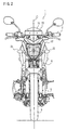
Fig. 2 is a front view of the motorcycle shown inFig. 1 . -
Fig. 3 is a plan view of the motorcycle shown inFig. 1 . -
Fig. 4 is a left side view of a headlight unit, a meter unit, a meter visor, and a vehicle registration plate shown inFig. 1 . -
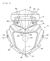
Fig. 5 is a front view of the headlight unit, the meter visor, and the vehicle registration plate shown inFig. 4 . -
Fig. 6 is a perspective view of the headlight unit, the meter unit, the meter visor, and the vehicle registration plate shown inFig. 4 . -
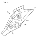
Fig. 7 is a left side view of the side cover of the headlight unit shown inFig. 4 . -
Fig. 8 is a plan view of the side cover shown inFig. 7 . -
Fig. 9 is a side view of the top cover of the headlight unit shown inFig. 4 . -
Fig. 10 is a plan view of the top cover shown inFig. 9 . -
Fig. 11 is a sectional view taken along line XI-XI inFig. 5 . -
Fig. 12 is a perspective view of the meter unit, the meter visor, and the vehicle registration plate shown inFig. 4 when viewed in the XII direction inFig. 4 . -
Fig. 13 is a side view of the meter visor shown inFig. 4 . -
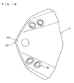
Fig. 14 is a plan view of the meter visor shown inFig. 13 . -
Fig. 15 is a front view of a headlight stay and a meter bracket shown inFig. 4 . -
Fig. 16 is a left side view of the headlight stay and the meter bracket shown inFig. 15 . -
Fig. 17 is a bottom view of the headlight stay shown inFig. 15 . -
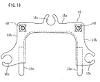
Fig. 18 is a plan view of the meter bracket shown inFig. 15 . -
Fig. 19 is a front view of a visor bracket shown inFig. 4 . -
Fig. 20 is a side view of the visor bracket shown inFig. 19 . -
Fig. 21 is a partial front view of a plate bracket shown inFig. 4 . -
Fig. 22 is a side view of the plate bracket shown inFig. 21 . - A preferred embodiment of the present invention will be described in detail in conjunction with the accompanying drawings in which the same or corresponding elements are designated by the same reference characters and their description will not be repeated.
- In the following description, the "front," "rear," "right," and "left" refer to these directions as viewed from a rider on a seat unless otherwise specified.
- Referring to
Figs. 1 to 3 , amotorcycle 1 includes abody frame 2, afront wheel 3, a rear wheel 4, anengine 5, afront fork 6, ahandle 7, a rear arm 8, afuel tank 9, and aseat 10. Thefront wheel 3 and the rear wheel 4 are supported by thebody frame 2. Theengine 5 is supported by thebody frame 2 and provided between thefront wheel 3 and the rear wheel 4. - The
motorcycle 1 further includes ahead pipe 2a. Thehead pipe 2a is formed at the front end of thebody frame 2. Thefront fork 6 is supported rotatably at thehead pipe 2a. Thefront fork 6 includesouter tubes 6a andinner tubes 6b. Thefront wheel 3 is supported rotatably at the lower ends of theouter tubes 6a. The twoinner tubes 6b on the right and left are coupled by anupper bracket 6c and alower bracket 6d. Ahandle 7 is attached to theupper bracket 6c throughhandle crowns 6e shown inFig. 3 . Therefore, thehandle 7 is supported so that it can steer rightward or leftward around the steering shaft of thefront fork 6. The rear arm 8 is swingably supported upward or downward around therear arm bracket 2b of thebody frame 2. The rear wheel 4 is supported rotatably at the rear end of the rear arm 8. Theengine 5 is for example a water-cooling type, four-cycle single cylinder engine. Theengine 5 is supported at the main frame (not shown) and therear arm bracket 2b of thebody frame 2. Thefuel tank 9 is provided above theengine 5. Theseat 10 is provided behind thefuel tank 9. - The
motorcycle 1 further includes a meter unit (also referred to as a "meter assembly") 11, a headlight unit (also referred to as a "headlight assembly") 12, a vehicle registration plate 13 (also referred to as a "number plate" or "license plate") 13, ameter visor 14, andwinkers 21. - The
meter unit 11 is provided above and in front of thehead pipe 2a. Theheadlight unit 12 is provided in front of thehead pipe 2a. More specifically, theheadlight unit 12 is provided under themeter unit 11. Themeter visor 14 is provided in front of themeter unit 12. Thevehicle registration plate 13 is attached above themeter visor 14. More specifically, thevehicle registration plate 13 is provided in front of themeter unit 11 and above theheadlight unit 12. Themeter visor 14 is provided between themeter unit 11 and thevehicle registration plate 13. - Referring to
Figs. 4 to 6 , theheadlight unit 12 includes aheadlight 18, right and left side covers 19, and atop cover 20. As shown inFig. 5 , theheadlight 18 is provided in the center of theheadlight unit 12. As shown inFigs. 4 to 6 , theleft side cover 19 is provided on the left side of theheadlight unit 12 and extends to the vicinity of the upper end of thefront fork 6 from the left edge of theheadlight 18. Theright side cover 19 is formed symmetrically to theleft side cover 19 with respect to the central line C of the motorcycle. Thetop cover 20 is provided on the upper side of theheadlight unit 12 and extends to the vicinity of the back surface of themeter unit 11 from the upper edge of theheadlight 18. The upper edge of theleft side cover 19 is connected to the left edge of thetop cover 20. The upper edge of theright side cover 19 is connected to the right edge of thetop cover 20. - As shown in
Figs. 7 and8 , theleft side cover 19 has two countersinkholes 19a. The side cover 19 also has anattachment hole 19d for theleft winker 21. Similarly, theright side cover 19 has two countersink holes (not shown) and an attachment hole (not shown) for theright winker 21. Abolt 19b is laterally inserted into thecountersink hole 19a and screwed to thelight case 18h (Fig. 11 ) of theheadlight 18 that will be described. In this way, theside cover 19 is attached to theheadlight 18. Thetop cover 20 has acentral attachment member 20a and a pair of right and leftattachment members 20b as shown inFigs. 9 and10 . - As shown in
Fig. 4 , the rear end 19' of theside cover 19 is provided above thelower end 2a' of thehead pipe 2a when viewed from a lateral side of the motorcycle. Therefore, theheadlight unit 12 may be provided as near as possible to thehead pipe 2a. - As shown in
Figs. 5 and6 , thetop cover 20 has downward recesses 20d. Therecesses 20d are formed symmetrically with respect to the central line C of the motorcycle. - As shown in
Fig. 11 , theheadlight 18 includes alight case 18h, atransparent cover 18f, and alight bulb 181. Thetransparent cover 18f is provided to cover the front opening of thelight case 18h. Thelight bulb 181 is a light source and provided in thelight case 18h. The periphery of thelight bulb 181 at the inner surface of thelight case 18h has areflection surface 18i. As shown inFig. 5 , thelight bulb 181 is provided in the center in the widthwise direction of the motorcycle, in other words, on the central line C of the motorcycle. - As shown in
Fig. 11 , acentral support member 18d is formed above thelight case 18h. Thecentral attachment member 20a of thetop cover 20 shown inFigs. 9 and10 is screwed to thecentral support member 18d of thelight case 18h by abolt 20c. Although not shown, the right and leftattachment members 20b of thetop cover 20 shown inFigs. 9 and10 are similarly screwed to the right and left support members of thelight case 18h by bolts. In this way, thetop cover 20 is attached to theheadlight 18. - Referring to
Fig. 4 , themeter unit 11 is attached to thefront fork 6. The rear end 11' of themeter unit 11 is positioned substantially immediately above thelower end 2a' of thehead pipe 2a. Therefore, themeter unit 11 may be provided as near as possible to thehead pipe 2a. - Referring to
Fig. 12 , themeter unit 11 includes ameter case 11a and ameter panel 11b. Themeter panel 11b is provided in themeter case 11a. As shown inFig. 5 , themeter panel 11b stores meters such as aspeed meter 11c, anodometer 11d, and atachometer 11e. - Referring to
Figs. 4 to 6 , themeter visor 14 is provided above thetop cover 20 of theheadlight unit 12. Themeter visor 14 is curved to surround thefront portion 11" of themeter unit 11. As shown inFig. 4 , themeter visor 14 overlaps thefront portion 11" of themeter unit 11 when viewed from a lateral side of the motorcycle. As shown inFigs. 4 and6 , thelower portion 14c of themeter visor 14 is positioned in front of thevehicle registration plate 13. As shown inFig. 4 , when viewed in the orthogonal direction VII to themeter panel 11b, themeter visor 14 overlaps thevehicle registration plate 13 in the center of the motorcycle widthwise direction as shown inFig. 12 . More specifically, the central portion 13' of thevehicle registration plate 13 is shielded by the central portion 14' of themeter visor 14. The size L2 of themeter visor 14 in the motorcycle widthwise direction is equal to or longer than the size L1 of thevehicle registration plate 13. Themeter visor 14 prevents sunlight from lowering the visibility of themeter unit 11 and light from theheadlight 18 from being reflected by the back surface of thevehicle registration plate 13 to get into the rider's eyes. - As shown in
Fig. 4 , when viewed from a lateral side of the motorcycle, themeter visor 14 is provided above theside cover 19. Therefore, themeter visor 14 may be provided as near as possible to thehead pipe 2a. As shown inFig. 5 , thelower part 14c of themeter visor 14 overlaps therecesses 20d of thetop cover 20 when viewed from the front of the motorcycle. Thelowermost end 14c' of themeter visor 14 is provided on the central line C of the motorcycle. Therefore, themeter visor 14 may be provided as near as possible to themeter unit 11. - As shown in
Figs. 13 and14 , themeter visor 14 has twoattachment holes 14b each in the left part and the right part. Themeter visor 14 is provided between themeter unit 11 and thevehicle registration plate 13 and above theheadlight 18. - As shown in
Figs. 4 to 6 , thevehicle registration plate 13 is a thin rectangular plate. Thevehicle registration plate 13 has longer sides provided along the widthwise direction of the motorcycle and shorter sides provided substantially along the vertical direction V As shown inFig. 4 , thevehicle registration plate 13 is provided above theside cover 19 when viewed from a lateral side of the motorcycle. The back surface of thevehicle registration plate 13 may be coated with black plating in order to reduce the reflection of light from theheadlight 18. - As shown in
Fig. 4 , thefront edge 18f' (positioned on the center line C in the motorcycle widthwise direction inFig. 5 ) of thetransparent cover 18f of theheadlight 18 is inclined at least at an angle θ1 with respect to the vertical line V When viewed from a lateral side of the motorcycle, thevehicle registration plate 13 is inclined backward at an angle θ2 with respect to the vertical line V The angle θ2 is smaller than the angle θ1. More specifically, thevehicle registration plate 13 is provided substantially in the vertical direction. - As shown in
Fig. 4 , when viewed from a lateral side of the motorcycle, thevehicle registration plate 13 is provided above theside cover 19. Therefore, thevehicle registration plate 13 may be provided as near as possible to thehead pipe 2a. - The
motorcycle 1 further includes aheadlight stay 16 and ameter bracket 15 shown inFigs. 15 to 17 . As shown inFig. 4 , theheadlight stay 16 is a component used to attach theheadlight unit 12 to thefront fork 6. - As shown in
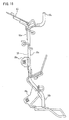
Fig. 15 , theheadlight stay 16 includes a pair of right and leftround rods 16a and acoupling plate 16b. Theround rods 16a extend in the vertical direction. Thecoupling plate 16b is fixed at the lower ends of theround rods 16a. The connectingrod 15e of themeter bracket 15 that will be described is welded to the upper ends of theround rods 16a. Theheadlight stay 16 and themeter bracket 15 have substantially a rectangular shape when viewed from the front. Theround rods 16a have their upper ends bent backward to formengagement portions 16c. As shown inFig. 4 , the lower surface of theupper bracket 6c of thefront fork 6 has anengagement recess 6f. Theengagement portion 16c is secured to theengagement recess 6f through adamper 17. Thecoupling plate 16b is fixed to thelower bracket 6d of thefront fork 6 by abolt 16d. In this way, theheadlight stay 16 is attached to thefront fork 6. - As shown in
Figs. 15 and16 , the headlight stay 16 further includes a pair of right and leftsupport members 16e. As shown inFig. 4 ,attachment members 18a are provided in the right and left parts of theheadlight 18. Abolt 16f is inserted laterally into the attachment hole of theattachment member 18a and screwed to thesupport member 16e of theheadlight stay 16. - As shown in
Figs. 15 to 17 , the headlight stay 16 further includes a pair of right and leftsupport members 16g. As shown inFig. 4 , anadjuster 18b is formed in the left part of the bottom of theheadlight 18. Theadjuster 18b is attached to thesupport member 16g of the headlight stay 16 by abolt 16h. Thebolt 16h is inserted laterally in an elongate hole formed in theadjuster 18b and screwed to thesupport member 16g of theheadlight stay 16. When thebolt 16h is loosened, theentire headlight unit 12 can be rotated around thebolt 16f. In this way, the optical axis of theheadlight 18 can be adjusted. - As shown in
Fig. 4 , themeter bracket 15 is a component used to attach themeter unit 11 to thefront fork 6. As shown inFig. 18 , themeter bracket 15 includes afront side 15a and a pair of right and leftsides 15b. Themeter bracket 15 is made of a sheet metal and substantially C-shaped when viewed in a plan view. - As shown in
Figs. 15 ,16 , and18 , themeter bracket 15 further includes a pair of right and left connectingrods 15e. The connectingrods 15e are welded to the upper ends of theround rods 16a of theheadlight stay 16, so that themeter bracket 15 is coupled to theheadlight stay 16. - As shown in
Figs. 15 and18 , attachment holes 15c are formed at the central part of thefront side 15a and the rear ends of thesides 15b. As shown inFig. 4 , a bolt 15d is inserted into theattachment hole 15c from below and fastened to the bottom of themeter case 11a. In this way, themeter unit 11 is attached to themeter bracket 15. Therefore, themeter unit 11 is attached to thefront fork 6 through themeter bracket 15 and theheadlight stay 16. - The
motorcycle 1 further includes avisor bracket 23 shown inFigs. 19 and20 . As shown inFig. 4 , thevisor bracket 23 is a component used to attach themeter visor 14 to themeter bracket 15. - As shown in
Figs. 19 and20 , thevisor bracket 23 includes a pair of right and leftsupport members 23a, a pair of right and leftcoupling members 23b, and acoupling member 23c used to couple them. Thesupport members 23a each have twocollars 23d used to attach thevehicle registration plate 13 and themeter visor 14. Thecoupling members 23b each have anattachment hole 23f. Abolt 23e is inserted into theattachment hole 23f of thevisor bracket 23 from below and screwed to thescrew hole 15f of thebracket 15. In this way, thevisor bracket 23 is attached to themeter bracket 15. - The
motorcycle 1 further includes aplate bracket 22 as shown inFigs. 21 and22 . As shown inFigs. 4 and5 , theplate bracket 22 is a component used to attach thevehicle registration plate 13 to themeter visor 14. - As shown in
Figs. 21 and22 , theplate bracket 22 includes aplate attachment portion 22a, a pair of right and leftlegs 22b, and a pair of right and leftcoupling members 22c. Theplate attachment member 22a is a strip shaped plate that extends in the motorcycle widthwise direction. Theplate attachment portion 22a has twoscrew holes 22f in the right and the left parts. The right and left ends of theplate attachment portion 22a are bent backward to form thelegs 22b. Thelegs 22b are further bent outward in the motorcycle widthwise direction to form thecoupling members 22c. Thecoupling members 22c each have twoattachment holes 22g. - As shown in
Figs. 4 to 6 ,bolts 22e are inserted into the attachment holes (not shown) of thevehicle registration plate 13 from the front and screwed to the screw holes 22f of theplate bracket 22. Therefore, thevehicle registration plate 13 is attached to theplate bracket 22 by thebolts 22e. - As shown in
Figs. 4 to 6 ,bolts 22d are inserted into the attachment holes 22g (Figs. 21 to 22 ) of theplate bracket 22 from above and further into the attachment holes 14b (Figs. 13 and14 ) of themeter visor 14 and screwed to thecollars 23d (Figs. 19 and20 ) of thevisor bracket 23. Therefore, theplate bracket 22 and themeter visor 14 are attached to thevisor bracket 23 by thebolts 22d. As a result, thevehicle registration plate 13 is attached to thefront fork 6 through theplate bracket 22, thevisor bracket 23, and theheadlight stay 16. Themeter visor 14 is attached to thefront fork 6 through thevisor bracket 23 and theheadlight stay 16. - As described above, the
meter unit 11, theheadlight unit 12, thevehicle registration plate 13, and themeter visor 14 are attached to the headlight stay 16 to form a unit and attached to thefront fork 6 together as the unit. - According to the present preferred embodiment, the
vehicle registration plate 13 is attached above themeter visor 14, so that thevehicle registration plate 13 does not come within sight of the rider. Furthermore, thevehicle registration plate 13 does not get in the way, when theheadlight unit 12 and themeter unit 11 are positioned close to the center of gravity of themotorcycle 1. - The
meter visor 14 overlaps thevehicle registration plate 13 in the center of the motorcycle widthwise direction from a view point in the orthogonal direction XII to themeter panel 11b. Therefore, if light from thelight bulb 181 of theheadlight 18 is reflected by the back surface of thevehicle registration plate 13, the light hardly comes in the rider's eyes. - The
lower portion 14c of themeter visor 14 is positioned in front of thevehicle registration plate 13. Therefore, light from theheadlight 18 is shielded by thelower portion 14c of themeter visor 14 and unlikely to reach the back surface of thevehicle registration plate 13. - The size L2 of the
meter visor 14 in the motorcycle widthwise direction is equal to or larger than the size L1 of thevehicle registration plate 13 in the motorcycle widthwise direction. Therefore, if light from theheadlight 18 is reflected by the back surface of thevehicle registration plate 13, the light hardly comes in the rider's eyes. - When viewed from a lateral side of the motorcycle, the central line C of the
transparent cover 18f of theheadlight 18 in the motorcycle widthwise direction is inclined at an angle θ1 or more with respect to the vertical line V, and thevehicle registration plate 13 is inclined backward at an angle θ2 that is smaller than the angle θ1 with respect to the vertical line V Therefore, light from theheadlight 18 hardly reaches the back surface of thevehicle registration plate 13. - When viewed from a lateral side of the motorcycle, the
meter visor 14 overlaps thefront portion 11" of themeter unit 11, and sunlight hardly reaches themeter panel 11b. - Since the
rear end 11" of themeter unit 11 is positioned substantially immediately above thelower end 2a' of thehead pipe 2a, themeter unit 11 may be provided close to the center of gravity of themotorcycle 1. - The
headlight unit 12, themeter unit 11, and themeter visor 14 are attached to theheadlight stay 16, and thevehicle registration plate 13 is attached above themeter visor 14. Therefore, these fourcomponents 11 to 14 may be attached to the head stay 16 in advance to form a unit and may be attached to thefront fork 6 together as the unit. Furthermore, when thehandle 7 is turned to the right or left, the fourcomponents 11 to 14 are turned together with thefront fork 6, and therefore these fourcomponents 11 to 14 do not collide against one another. - When viewed from the front of the motorcycle, the
lower portion 14c of themeter visor 14 overlaps therecesses 20d of thetop cover 20. Therefore, thetop cover 20 does not get in the way when themeter visor 14 is positioned close to the center of gravity of themotorcycle 1. - When viewed from a lateral side of the motorcycle, the rear end 19' of the
side cover 19 is provided above thelower end 2a' of thehead pipe 2a, and themeter visor 14 and thevehicle registration plate 13 are provided above theside cover 19. Therefore, theside cover 19, themeter visor 14, and thevehicle registration plate 13 may be provided close to the center of gravity of themotorcycle 1.
Claims (11)
- A motorcycle (1), comprising:a head pipe (2a);a headlight unit (12) provided in front of the head pipe (2a) and including a headlight (18);a meter unit (11) provided above the head pipe (2a) and including a meter panel (11b);a meter visor (14) provided in front of the meter unit (11); anda vehicle registration plate (13) attached above the meter visor (14).
- The motorcycle (1) according to claim 1, wherein the headlight (18) comprises a light source (181) provided in the center in the widthwise direction of the motorcycle, and
from a view point in the orthogonal direction (XII) to the meter panel (11b), the meter visor (14) overlaps the vehicle registration plate (13) in the center in the widthwise direction of the motorcycle. - The motorcycle (1) according to claim 1, wherein the meter visor (14) has a lower portion (14c) positioned in front of the vehicle registration plate (13).
- The motorcycle (1) according to claim 1, wherein in the widthwise direction of the motorcycle, the meter visor (14) has a size (L2) equal to or larger than the size (L1) of the vehicle registration plate (13).
- The motorcycle (1) according to claim 1, wherein the headlight (18) comprises a transparent cover (18f) provided at a front surface of the headlight (18), and
when viewed from a lateral side of the motorcycle, the central line (C) of the transparent cover (18f) in the widthwise direction of the motorcycle is inclined backward at least at a first angle (θ1) with respect to the vertical line (V), and the vehicle registration plate (13) is inclined backward at an angle (θ2) smaller than the first angle (θ1) with respect to the vertical line (V). - The motorcycle (1) according to claim 1, wherein the meter visor (14) overlaps at least a part (11") of the meter unit (11) when viewed from a lateral side of the motorcycle.
- The motorcycle (1) according to claim 1, wherein the head pipe (2a) has a lower end (2a'), and
the meter unit (11) has a rear end (11') positioned substantially immediately above the lower end (2a') of the head pipe (2a). - The motorcycle (1) according to claim 1, further comprising a front fork (6) supported rotatably at the head pipe (2a), and
the headlight unit (12), the meter unit (11), and the meter visor (14) are attached to the front fork (6). - The motorcycle (1) according to claim 8, further comprising a headlight stay (16) attached to the front fork (6), wherein the headlight unit (12), the meter unit (11), and the meter visor (14) are attached to the headlight stay (16).
- The motorcycle (1) according to claim 1, wherein the headlight unit (12) comprises a top cover (20) provided on an upper side of the headlight unit (12),
the top cover (20) comprises a downward recess (20d), and
the meter visor (14) has a lower portion (14c) that overlaps the recess (20d) of the top cover (20) when viewed from the front of the motorcycle. - The motorcycle (1) according to claim 1, wherein the head pipe (2a) has a lower end (2a'),
the headlight unit (12) comprises a side cover (19) provided at a lateral side of the headlight unit (12),
the side cover (19) has a rear end (19') provided above the lower end (2a') of the head pipe (2a) when viewed from a lateral side of the motorcycle, and
the meter visor (14) and the vehicle registration plate (13) are provided above the side cover (19) when viewed from a lateral side of the motorcycle.
Applications Claiming Priority (1)
| Application Number | Priority Date | Filing Date | Title |
|---|---|---|---|
| JP2009052581A JP2010202145A (en) | 2009-03-05 | 2009-03-05 | Motorcycle |
Publications (2)
| Publication Number | Publication Date |
|---|---|
| EP2226241A1 true EP2226241A1 (en) | 2010-09-08 |
| EP2226241B1 EP2226241B1 (en) | 2011-05-11 |
Family
ID=41820702
Family Applications (1)
| Application Number | Title | Priority Date | Filing Date |
|---|---|---|---|
| EP10154804A Active EP2226241B1 (en) | 2009-03-05 | 2010-02-26 | Motorcycle including vehicle registration plate at front thereof |
Country Status (4)
| Country | Link |
|---|---|
| EP (1) | EP2226241B1 (en) |
| JP (1) | JP2010202145A (en) |
| AT (1) | ATE508935T1 (en) |
| CO (1) | CO6340178A1 (en) |
Cited By (6)
| Publication number | Priority date | Publication date | Assignee | Title |
|---|---|---|---|---|
| CN102514660A (en) * | 2011-12-15 | 2012-06-27 | 江门市大长江集团有限公司 | Motorcycle head structure |
| EP2949567A1 (en) | 2014-05-30 | 2015-12-02 | Yamaha Motor Co., Ltd. | Straddle type vehicle with single cylinder engine |
| EP3015349A1 (en) * | 2014-10-31 | 2016-05-04 | Yamaha Hatsudoki Kabushiki Kaisha | Vehicle |
| CN109050742A (en) * | 2018-07-28 | 2018-12-21 | 重庆隆鑫机车有限公司 | Motorcycle instrument mounting structure and its motorcycle |
| CN109383682A (en) * | 2018-11-28 | 2019-02-26 | 南京金城机械有限公司 | Motorcycle head mounting connection structure |
| WO2024184916A1 (en) * | 2023-03-05 | 2024-09-12 | Tvs Motor Company Limited | A handlebar cover for a vehicle |
Families Citing this family (2)
| Publication number | Priority date | Publication date | Assignee | Title |
|---|---|---|---|---|
| JP5969785B2 (en) * | 2012-03-21 | 2016-08-17 | 川崎重工業株式会社 | Saddle riding vehicle |
| JP6840244B2 (en) * | 2017-08-09 | 2021-03-10 | 本田技研工業株式会社 | License plate mounting part structure of saddle type vehicle |
Citations (3)
| Publication number | Priority date | Publication date | Assignee | Title |
|---|---|---|---|---|
| JPH06298144A (en) | 1993-04-17 | 1994-10-25 | Honda Motor Co Ltd | Headlight mounting structure for motorcycles |
| WO2008065676A2 (en) * | 2006-11-27 | 2008-06-05 | Bajaj Auto Limited | Mounting arrangement of number plate in a motorcycle |
| US20090127884A1 (en) * | 2007-10-31 | 2009-05-21 | Yamaha Hatsudoki Kabushiki Kaisha | Motorcycle and rectifier plate for the same |
-
2009
- 2009-03-05 JP JP2009052581A patent/JP2010202145A/en not_active Withdrawn
-
2010
- 2010-02-26 EP EP10154804A patent/EP2226241B1/en active Active
- 2010-02-26 AT AT10154804T patent/ATE508935T1/en not_active IP Right Cessation
- 2010-03-04 CO CO10025575A patent/CO6340178A1/en active IP Right Grant
Patent Citations (3)
| Publication number | Priority date | Publication date | Assignee | Title |
|---|---|---|---|---|
| JPH06298144A (en) | 1993-04-17 | 1994-10-25 | Honda Motor Co Ltd | Headlight mounting structure for motorcycles |
| WO2008065676A2 (en) * | 2006-11-27 | 2008-06-05 | Bajaj Auto Limited | Mounting arrangement of number plate in a motorcycle |
| US20090127884A1 (en) * | 2007-10-31 | 2009-05-21 | Yamaha Hatsudoki Kabushiki Kaisha | Motorcycle and rectifier plate for the same |
Cited By (11)
| Publication number | Priority date | Publication date | Assignee | Title |
|---|---|---|---|---|
| CN102514660A (en) * | 2011-12-15 | 2012-06-27 | 江门市大长江集团有限公司 | Motorcycle head structure |
| CN102514660B (en) * | 2011-12-15 | 2014-09-03 | 江门市大长江集团有限公司 | Motorcycle head structure |
| EP2949567A1 (en) | 2014-05-30 | 2015-12-02 | Yamaha Motor Co., Ltd. | Straddle type vehicle with single cylinder engine |
| EP3015349A1 (en) * | 2014-10-31 | 2016-05-04 | Yamaha Hatsudoki Kabushiki Kaisha | Vehicle |
| CN105564548A (en) * | 2014-10-31 | 2016-05-11 | 雅马哈发动机株式会社 | Vehicle |
| CN105564548B (en) * | 2014-10-31 | 2018-06-19 | 雅马哈发动机株式会社 | Vehicle |
| CN109050742A (en) * | 2018-07-28 | 2018-12-21 | 重庆隆鑫机车有限公司 | Motorcycle instrument mounting structure and its motorcycle |
| CN109050742B (en) * | 2018-07-28 | 2023-08-25 | 重庆隆鑫机车有限公司 | Motorcycle instrument mounting structure and motorcycle thereof |
| CN109383682A (en) * | 2018-11-28 | 2019-02-26 | 南京金城机械有限公司 | Motorcycle head mounting connection structure |
| CN109383682B (en) * | 2018-11-28 | 2024-01-19 | 南京金城机械有限公司 | Motorcycle head mounting connection structure |
| WO2024184916A1 (en) * | 2023-03-05 | 2024-09-12 | Tvs Motor Company Limited | A handlebar cover for a vehicle |
Also Published As
| Publication number | Publication date |
|---|---|
| ATE508935T1 (en) | 2011-05-15 |
| EP2226241B1 (en) | 2011-05-11 |
| CO6340178A1 (en) | 2011-11-21 |
| JP2010202145A (en) | 2010-09-16 |
Similar Documents
| Publication | Publication Date | Title |
|---|---|---|
| EP2226241B1 (en) | Motorcycle including vehicle registration plate at front thereof | |
| JP6399532B2 (en) | Direction indicator for small vehicles | |
| EP2390170B1 (en) | Motorcycle | |
| US9260058B2 (en) | Saddle-ride type vehicle | |
| EP3378751A1 (en) | Rear fender supporting structure of saddle-type vehicle | |
| US12024255B2 (en) | Straddle type vehicle | |
| JP5009110B2 (en) | Motorcycle meter arrangement structure | |
| CN110450892B (en) | Automatic two-wheel vehicle | |
| JP5208097B2 (en) | Motorcycle meter equipment | |
| US20230192213A1 (en) | Straddle-type vehicle | |
| JP5748530B2 (en) | Position light, headlight structure and cowl structure for saddle riding type vehicles | |
| US11613324B2 (en) | Saddle riding vehicle | |
| EP3118093B1 (en) | Direction indicator structure of vehicle | |
| EP4488153A1 (en) | Vehicle front structure | |
| JP7245861B2 (en) | Number plate mounting structure for saddle type vehicle | |
| JP2014198528A (en) | Support mechanism of headlight | |
| EP3015353B1 (en) | Straddle-type vehicle | |
| US10379343B2 (en) | Saddle riding vehicle | |
| JP3288828B2 (en) | Mounting structure for headlights of vehicles such as motorcycles | |
| US11964724B2 (en) | Fixing structure of screen | |
| JP2010274851A (en) | Motorcycle and step holder | |
| JPH09142354A (en) | Motorcycle visor mounting structure | |
| JP7245630B2 (en) | Straddle-type vehicle and meter visor | |
| JP2007001533A (en) | Motorcycle | |
| JP2019181970A (en) | Saddle-riding type vehicle |
Legal Events
| Date | Code | Title | Description |
|---|---|---|---|
| PUAI | Public reference made under article 153(3) epc to a published international application that has entered the european phase |
Free format text: ORIGINAL CODE: 0009012 |
|
| 17P | Request for examination filed |
Effective date: 20100723 |
|
| AK | Designated contracting states |
Kind code of ref document: A1 Designated state(s): AT BE BG CH CY CZ DE DK EE ES FI FR GB GR HR HU IE IS IT LI LT LU LV MC MK MT NL NO PL PT RO SE SI SK SM TR |
|
| AX | Request for extension of the european patent |
Extension state: AL BA RS |
|
| GRAP | Despatch of communication of intention to grant a patent |
Free format text: ORIGINAL CODE: EPIDOSNIGR1 |
|
| RIC1 | Information provided on ipc code assigned before grant |
Ipc: B62J 17/04 20060101AFI20100910BHEP Ipc: B62J 99/00 20090101ALI20100910BHEP |
|
| GRAS | Grant fee paid |
Free format text: ORIGINAL CODE: EPIDOSNIGR3 |
|
| GRAA | (expected) grant |
Free format text: ORIGINAL CODE: 0009210 |
|
| AK | Designated contracting states |
Kind code of ref document: B1 Designated state(s): AT BE BG CH CY CZ DE DK EE ES FI FR GB GR HR HU IE IS IT LI LT LU LV MC MK MT NL NO PL PT RO SE SI SK SM TR |
|
| REG | Reference to a national code |
Ref country code: GB Ref legal event code: FG4D |
|
| REG | Reference to a national code |
Ref country code: CH Ref legal event code: EP |
|
| REG | Reference to a national code |
Ref country code: IE Ref legal event code: FG4D |
|
| REG | Reference to a national code |
Ref country code: DE Ref legal event code: R096 Ref document number: 602010000031 Country of ref document: DE Effective date: 20110622 |
|
| REG | Reference to a national code |
Ref country code: NL Ref legal event code: VDEP Effective date: 20110511 |
|
| PG25 | Lapsed in a contracting state [announced via postgrant information from national office to epo] |
Ref country code: NO Free format text: LAPSE BECAUSE OF FAILURE TO SUBMIT A TRANSLATION OF THE DESCRIPTION OR TO PAY THE FEE WITHIN THE PRESCRIBED TIME-LIMIT Effective date: 20110811 Ref country code: SE Free format text: LAPSE BECAUSE OF FAILURE TO SUBMIT A TRANSLATION OF THE DESCRIPTION OR TO PAY THE FEE WITHIN THE PRESCRIBED TIME-LIMIT Effective date: 20110511 Ref country code: PT Free format text: LAPSE BECAUSE OF FAILURE TO SUBMIT A TRANSLATION OF THE DESCRIPTION OR TO PAY THE FEE WITHIN THE PRESCRIBED TIME-LIMIT Effective date: 20110912 Ref country code: LT Free format text: LAPSE BECAUSE OF FAILURE TO SUBMIT A TRANSLATION OF THE DESCRIPTION OR TO PAY THE FEE WITHIN THE PRESCRIBED TIME-LIMIT Effective date: 20110511 |
|
| PG25 | Lapsed in a contracting state [announced via postgrant information from national office to epo] |
Ref country code: LV Free format text: LAPSE BECAUSE OF FAILURE TO SUBMIT A TRANSLATION OF THE DESCRIPTION OR TO PAY THE FEE WITHIN THE PRESCRIBED TIME-LIMIT Effective date: 20110511 Ref country code: GR Free format text: LAPSE BECAUSE OF FAILURE TO SUBMIT A TRANSLATION OF THE DESCRIPTION OR TO PAY THE FEE WITHIN THE PRESCRIBED TIME-LIMIT Effective date: 20110812 Ref country code: IS Free format text: LAPSE BECAUSE OF FAILURE TO SUBMIT A TRANSLATION OF THE DESCRIPTION OR TO PAY THE FEE WITHIN THE PRESCRIBED TIME-LIMIT Effective date: 20110911 Ref country code: BE Free format text: LAPSE BECAUSE OF FAILURE TO SUBMIT A TRANSLATION OF THE DESCRIPTION OR TO PAY THE FEE WITHIN THE PRESCRIBED TIME-LIMIT Effective date: 20110511 Ref country code: AT Free format text: LAPSE BECAUSE OF FAILURE TO SUBMIT A TRANSLATION OF THE DESCRIPTION OR TO PAY THE FEE WITHIN THE PRESCRIBED TIME-LIMIT Effective date: 20110511 Ref country code: FI Free format text: LAPSE BECAUSE OF FAILURE TO SUBMIT A TRANSLATION OF THE DESCRIPTION OR TO PAY THE FEE WITHIN THE PRESCRIBED TIME-LIMIT Effective date: 20110511 Ref country code: CY Free format text: LAPSE BECAUSE OF FAILURE TO SUBMIT A TRANSLATION OF THE DESCRIPTION OR TO PAY THE FEE WITHIN THE PRESCRIBED TIME-LIMIT Effective date: 20110511 Ref country code: ES Free format text: LAPSE BECAUSE OF FAILURE TO SUBMIT A TRANSLATION OF THE DESCRIPTION OR TO PAY THE FEE WITHIN THE PRESCRIBED TIME-LIMIT Effective date: 20110822 Ref country code: SI Free format text: LAPSE BECAUSE OF FAILURE TO SUBMIT A TRANSLATION OF THE DESCRIPTION OR TO PAY THE FEE WITHIN THE PRESCRIBED TIME-LIMIT Effective date: 20110511 |
|
| PG25 | Lapsed in a contracting state [announced via postgrant information from national office to epo] |
Ref country code: NL Free format text: LAPSE BECAUSE OF FAILURE TO SUBMIT A TRANSLATION OF THE DESCRIPTION OR TO PAY THE FEE WITHIN THE PRESCRIBED TIME-LIMIT Effective date: 20110511 |
|
| PG25 | Lapsed in a contracting state [announced via postgrant information from national office to epo] |
Ref country code: EE Free format text: LAPSE BECAUSE OF FAILURE TO SUBMIT A TRANSLATION OF THE DESCRIPTION OR TO PAY THE FEE WITHIN THE PRESCRIBED TIME-LIMIT Effective date: 20110511 Ref country code: CZ Free format text: LAPSE BECAUSE OF FAILURE TO SUBMIT A TRANSLATION OF THE DESCRIPTION OR TO PAY THE FEE WITHIN THE PRESCRIBED TIME-LIMIT Effective date: 20110511 |
|
| PG25 | Lapsed in a contracting state [announced via postgrant information from national office to epo] |
Ref country code: SK Free format text: LAPSE BECAUSE OF FAILURE TO SUBMIT A TRANSLATION OF THE DESCRIPTION OR TO PAY THE FEE WITHIN THE PRESCRIBED TIME-LIMIT Effective date: 20110511 Ref country code: PL Free format text: LAPSE BECAUSE OF FAILURE TO SUBMIT A TRANSLATION OF THE DESCRIPTION OR TO PAY THE FEE WITHIN THE PRESCRIBED TIME-LIMIT Effective date: 20110511 |
|
| PLBE | No opposition filed within time limit |
Free format text: ORIGINAL CODE: 0009261 |
|
| STAA | Information on the status of an ep patent application or granted ep patent |
Free format text: STATUS: NO OPPOSITION FILED WITHIN TIME LIMIT |
|
| 26N | No opposition filed |
Effective date: 20120214 |
|
| PG25 | Lapsed in a contracting state [announced via postgrant information from national office to epo] |
Ref country code: HR Free format text: LAPSE BECAUSE OF FAILURE TO SUBMIT A TRANSLATION OF THE DESCRIPTION OR TO PAY THE FEE WITHIN THE PRESCRIBED TIME-LIMIT Effective date: 20111123 Ref country code: IT Free format text: LAPSE BECAUSE OF FAILURE TO SUBMIT A TRANSLATION OF THE DESCRIPTION OR TO PAY THE FEE WITHIN THE PRESCRIBED TIME-LIMIT Effective date: 20110511 |
|
| REG | Reference to a national code |
Ref country code: DE Ref legal event code: R097 Ref document number: 602010000031 Country of ref document: DE Effective date: 20120214 |
|
| PG25 | Lapsed in a contracting state [announced via postgrant information from national office to epo] |
Ref country code: MC Free format text: LAPSE BECAUSE OF NON-PAYMENT OF DUE FEES Effective date: 20120229 |
|
| REG | Reference to a national code |
Ref country code: IE Ref legal event code: MM4A |
|
| REG | Reference to a national code |
Ref country code: FR Ref legal event code: ST Effective date: 20121031 |
|
| REG | Reference to a national code |
Ref country code: DE Ref legal event code: R119 Ref document number: 602010000031 Country of ref document: DE Effective date: 20120901 |
|
| PG25 | Lapsed in a contracting state [announced via postgrant information from national office to epo] |
Ref country code: IE Free format text: LAPSE BECAUSE OF NON-PAYMENT OF DUE FEES Effective date: 20120226 Ref country code: FR Free format text: LAPSE BECAUSE OF NON-PAYMENT OF DUE FEES Effective date: 20120229 |
|
| PG25 | Lapsed in a contracting state [announced via postgrant information from national office to epo] |
Ref country code: MK Free format text: LAPSE BECAUSE OF FAILURE TO SUBMIT A TRANSLATION OF THE DESCRIPTION OR TO PAY THE FEE WITHIN THE PRESCRIBED TIME-LIMIT Effective date: 20110511 |
|
| PG25 | Lapsed in a contracting state [announced via postgrant information from national office to epo] |
Ref country code: BG Free format text: LAPSE BECAUSE OF FAILURE TO SUBMIT A TRANSLATION OF THE DESCRIPTION OR TO PAY THE FEE WITHIN THE PRESCRIBED TIME-LIMIT Effective date: 20110811 Ref country code: DE Free format text: LAPSE BECAUSE OF NON-PAYMENT OF DUE FEES Effective date: 20120901 |
|
| PG25 | Lapsed in a contracting state [announced via postgrant information from national office to epo] |
Ref country code: MT Free format text: LAPSE BECAUSE OF FAILURE TO SUBMIT A TRANSLATION OF THE DESCRIPTION OR TO PAY THE FEE WITHIN THE PRESCRIBED TIME-LIMIT Effective date: 20110511 |
|
| PG25 | Lapsed in a contracting state [announced via postgrant information from national office to epo] |
Ref country code: HR Free format text: LAPSE BECAUSE OF FAILURE TO SUBMIT A TRANSLATION OF THE DESCRIPTION OR TO PAY THE FEE WITHIN THE PRESCRIBED TIME-LIMIT Effective date: 20110511 |
|
| PG25 | Lapsed in a contracting state [announced via postgrant information from national office to epo] |
Ref country code: TR Free format text: LAPSE BECAUSE OF FAILURE TO SUBMIT A TRANSLATION OF THE DESCRIPTION OR TO PAY THE FEE WITHIN THE PRESCRIBED TIME-LIMIT Effective date: 20110511 |
|
| PG25 | Lapsed in a contracting state [announced via postgrant information from national office to epo] |
Ref country code: SM Free format text: LAPSE BECAUSE OF FAILURE TO SUBMIT A TRANSLATION OF THE DESCRIPTION OR TO PAY THE FEE WITHIN THE PRESCRIBED TIME-LIMIT Effective date: 20110511 Ref country code: LU Free format text: LAPSE BECAUSE OF NON-PAYMENT OF DUE FEES Effective date: 20120226 |
|
| PG25 | Lapsed in a contracting state [announced via postgrant information from national office to epo] |
Ref country code: HU Free format text: LAPSE BECAUSE OF FAILURE TO SUBMIT A TRANSLATION OF THE DESCRIPTION OR TO PAY THE FEE WITHIN THE PRESCRIBED TIME-LIMIT Effective date: 20100226 |
|
| REG | Reference to a national code |
Ref country code: CH Ref legal event code: PL |
|
| PG25 | Lapsed in a contracting state [announced via postgrant information from national office to epo] |
Ref country code: CH Free format text: LAPSE BECAUSE OF NON-PAYMENT OF DUE FEES Effective date: 20140228 Ref country code: LI Free format text: LAPSE BECAUSE OF NON-PAYMENT OF DUE FEES Effective date: 20140228 |
|
| P01 | Opt-out of the competence of the unified patent court (upc) registered |
Effective date: 20230527 |
|
| PGFP | Annual fee paid to national office [announced via postgrant information from national office to epo] |
Ref country code: GB Payment date: 20260219 Year of fee payment: 17 |