EP2226147A2 - Cold metal transfer gas metal arc welding apparatus and method of operation - Google Patents
Cold metal transfer gas metal arc welding apparatus and method of operation Download PDFInfo
- Publication number
- EP2226147A2 EP2226147A2 EP10250010A EP10250010A EP2226147A2 EP 2226147 A2 EP2226147 A2 EP 2226147A2 EP 10250010 A EP10250010 A EP 10250010A EP 10250010 A EP10250010 A EP 10250010A EP 2226147 A2 EP2226147 A2 EP 2226147A2
- Authority
- EP
- European Patent Office
- Prior art keywords
- cmt
- contact tip
- contact
- weld wire
- wire
- Prior art date
- Legal status (The legal status is an assumption and is not a legal conclusion. Google has not performed a legal analysis and makes no representation as to the accuracy of the status listed.)
- Granted
Links
- 229910052751 metal Inorganic materials 0.000 title claims abstract description 49
- 239000002184 metal Substances 0.000 title claims abstract description 49
- 238000003466 welding Methods 0.000 title claims abstract description 46
- 238000012546 transfer Methods 0.000 title claims abstract description 11
- 238000000034 method Methods 0.000 title claims description 14
- 229910000531 Co alloy Inorganic materials 0.000 claims description 17
- 239000010941 cobalt Substances 0.000 claims description 16
- 229910017052 cobalt Inorganic materials 0.000 claims description 16
- GUTLYIVDDKVIGB-UHFFFAOYSA-N cobalt atom Chemical compound [Co] GUTLYIVDDKVIGB-UHFFFAOYSA-N 0.000 claims description 16
- 229910052802 copper Inorganic materials 0.000 claims description 14
- 239000010949 copper Substances 0.000 claims description 14
- RYGMFSIKBFXOCR-UHFFFAOYSA-N Copper Chemical compound [Cu] RYGMFSIKBFXOCR-UHFFFAOYSA-N 0.000 claims description 13
- PXHVJJICTQNCMI-UHFFFAOYSA-N Nickel Chemical compound [Ni] PXHVJJICTQNCMI-UHFFFAOYSA-N 0.000 claims description 10
- 229910000990 Ni alloy Inorganic materials 0.000 claims description 9
- 229910052782 aluminium Inorganic materials 0.000 claims description 9
- XAGFODPZIPBFFR-UHFFFAOYSA-N aluminium Chemical group [Al] XAGFODPZIPBFFR-UHFFFAOYSA-N 0.000 claims description 9
- 239000000463 material Substances 0.000 claims description 9
- 229910001069 Ti alloy Inorganic materials 0.000 claims description 7
- 229910000838 Al alloy Inorganic materials 0.000 claims description 5
- RTAQQCXQSZGOHL-UHFFFAOYSA-N Titanium Chemical group [Ti] RTAQQCXQSZGOHL-UHFFFAOYSA-N 0.000 claims description 5
- 229910052759 nickel Inorganic materials 0.000 claims description 5
- 239000010935 stainless steel Substances 0.000 claims description 5
- 229910001220 stainless steel Inorganic materials 0.000 claims description 5
- 239000010936 titanium Substances 0.000 claims description 5
- 229910052719 titanium Inorganic materials 0.000 claims description 5
- 238000000151 deposition Methods 0.000 claims description 3
- 239000007789 gas Substances 0.000 description 23
- 229910045601 alloy Inorganic materials 0.000 description 5
- 239000000956 alloy Substances 0.000 description 5
- 230000010355 oscillation Effects 0.000 description 4
- 230000008439 repair process Effects 0.000 description 4
- 230000008901 benefit Effects 0.000 description 3
- 238000011109 contamination Methods 0.000 description 3
- 230000005611 electricity Effects 0.000 description 3
- 239000011261 inert gas Substances 0.000 description 3
- 239000002245 particle Substances 0.000 description 3
- XKRFYHLGVUSROY-UHFFFAOYSA-N Argon Chemical compound [Ar] XKRFYHLGVUSROY-UHFFFAOYSA-N 0.000 description 2
- CURLTUGMZLYLDI-UHFFFAOYSA-N Carbon dioxide Chemical compound O=C=O CURLTUGMZLYLDI-UHFFFAOYSA-N 0.000 description 2
- 239000000356 contaminant Substances 0.000 description 2
- 230000008569 process Effects 0.000 description 2
- 229910000881 Cu alloy Inorganic materials 0.000 description 1
- 230000004913 activation Effects 0.000 description 1
- 238000007792 addition Methods 0.000 description 1
- 229910052786 argon Inorganic materials 0.000 description 1
- 230000004323 axial length Effects 0.000 description 1
- 239000001569 carbon dioxide Substances 0.000 description 1
- 229910002092 carbon dioxide Inorganic materials 0.000 description 1
- -1 copper metals Chemical class 0.000 description 1
- 230000009849 deactivation Effects 0.000 description 1
- 230000007423 decrease Effects 0.000 description 1
- 238000013461 design Methods 0.000 description 1
- 239000000945 filler Substances 0.000 description 1
- 238000010438 heat treatment Methods 0.000 description 1
- 239000001307 helium Substances 0.000 description 1
- 229910052734 helium Inorganic materials 0.000 description 1
- SWQJXJOGLNCZEY-UHFFFAOYSA-N helium atom Chemical compound [He] SWQJXJOGLNCZEY-UHFFFAOYSA-N 0.000 description 1
- 238000003780 insertion Methods 0.000 description 1
- 230000037431 insertion Effects 0.000 description 1
- 238000004021 metal welding Methods 0.000 description 1
- 150000002739 metals Chemical class 0.000 description 1
- 239000000203 mixture Substances 0.000 description 1
- 238000012986 modification Methods 0.000 description 1
- 230000004048 modification Effects 0.000 description 1
- 239000007787 solid Substances 0.000 description 1
- 230000009897 systematic effect Effects 0.000 description 1
Images
Classifications
-
- B—PERFORMING OPERATIONS; TRANSPORTING
- B23—MACHINE TOOLS; METAL-WORKING NOT OTHERWISE PROVIDED FOR
- B23K—SOLDERING OR UNSOLDERING; WELDING; CLADDING OR PLATING BY SOLDERING OR WELDING; CUTTING BY APPLYING HEAT LOCALLY, e.g. FLAME CUTTING; WORKING BY LASER BEAM
- B23K9/00—Arc welding or cutting
- B23K9/02—Seam welding; Backing means; Inserts
- B23K9/022—Welding by making use of electrode vibrations
-
- B—PERFORMING OPERATIONS; TRANSPORTING
- B23—MACHINE TOOLS; METAL-WORKING NOT OTHERWISE PROVIDED FOR
- B23K—SOLDERING OR UNSOLDERING; WELDING; CLADDING OR PLATING BY SOLDERING OR WELDING; CUTTING BY APPLYING HEAT LOCALLY, e.g. FLAME CUTTING; WORKING BY LASER BEAM
- B23K9/00—Arc welding or cutting
- B23K9/16—Arc welding or cutting making use of shielding gas
- B23K9/173—Arc welding or cutting making use of shielding gas and of a consumable electrode
-
- B—PERFORMING OPERATIONS; TRANSPORTING
- B23—MACHINE TOOLS; METAL-WORKING NOT OTHERWISE PROVIDED FOR
- B23K—SOLDERING OR UNSOLDERING; WELDING; CLADDING OR PLATING BY SOLDERING OR WELDING; CUTTING BY APPLYING HEAT LOCALLY, e.g. FLAME CUTTING; WORKING BY LASER BEAM
- B23K9/00—Arc welding or cutting
- B23K9/23—Arc welding or cutting taking account of the properties of the materials to be welded
-
- B—PERFORMING OPERATIONS; TRANSPORTING
- B23—MACHINE TOOLS; METAL-WORKING NOT OTHERWISE PROVIDED FOR
- B23K—SOLDERING OR UNSOLDERING; WELDING; CLADDING OR PLATING BY SOLDERING OR WELDING; CUTTING BY APPLYING HEAT LOCALLY, e.g. FLAME CUTTING; WORKING BY LASER BEAM
- B23K9/00—Arc welding or cutting
- B23K9/24—Features related to electrodes
- B23K9/28—Supporting devices for electrodes
-
- B—PERFORMING OPERATIONS; TRANSPORTING
- B23—MACHINE TOOLS; METAL-WORKING NOT OTHERWISE PROVIDED FOR
- B23P—METAL-WORKING NOT OTHERWISE PROVIDED FOR; COMBINED OPERATIONS; UNIVERSAL MACHINE TOOLS
- B23P6/00—Restoring or reconditioning objects
- B23P6/002—Repairing turbine components, e.g. moving or stationary blades, rotors
- B23P6/007—Repairing turbine components, e.g. moving or stationary blades, rotors using only additive methods, e.g. build-up welding
-
- F—MECHANICAL ENGINEERING; LIGHTING; HEATING; WEAPONS; BLASTING
- F01—MACHINES OR ENGINES IN GENERAL; ENGINE PLANTS IN GENERAL; STEAM ENGINES
- F01D—NON-POSITIVE DISPLACEMENT MACHINES OR ENGINES, e.g. STEAM TURBINES
- F01D5/00—Blades; Blade-carrying members; Heating, heat-insulating, cooling or antivibration means on the blades or the members
- F01D5/005—Repairing methods or devices
-
- B—PERFORMING OPERATIONS; TRANSPORTING
- B23—MACHINE TOOLS; METAL-WORKING NOT OTHERWISE PROVIDED FOR
- B23K—SOLDERING OR UNSOLDERING; WELDING; CLADDING OR PLATING BY SOLDERING OR WELDING; CUTTING BY APPLYING HEAT LOCALLY, e.g. FLAME CUTTING; WORKING BY LASER BEAM
- B23K2101/00—Articles made by soldering, welding or cutting
- B23K2101/001—Turbines
-
- F—MECHANICAL ENGINEERING; LIGHTING; HEATING; WEAPONS; BLASTING
- F05—INDEXING SCHEMES RELATING TO ENGINES OR PUMPS IN VARIOUS SUBCLASSES OF CLASSES F01-F04
- F05D—INDEXING SCHEME FOR ASPECTS RELATING TO NON-POSITIVE-DISPLACEMENT MACHINES OR ENGINES, GAS-TURBINES OR JET-PROPULSION PLANTS
- F05D2230/00—Manufacture
- F05D2230/80—Repairing, retrofitting or upgrading methods
-
- F—MECHANICAL ENGINEERING; LIGHTING; HEATING; WEAPONS; BLASTING
- F05—INDEXING SCHEMES RELATING TO ENGINES OR PUMPS IN VARIOUS SUBCLASSES OF CLASSES F01-F04
- F05D—INDEXING SCHEME FOR ASPECTS RELATING TO NON-POSITIVE-DISPLACEMENT MACHINES OR ENGINES, GAS-TURBINES OR JET-PROPULSION PLANTS
- F05D2260/00—Function
- F05D2260/80—Diagnostics
Definitions
- the present invention relates to an arc welding apparatus, and in particular, to a cold metal transfer (CMT) welding apparatus and method of operation.
- CMT cold metal transfer
- GMAW Gas metal arc welding
- MIG metal inert gas
- MAG metal active gas
- GMAW Gas metal arc welding
- MIG metal inert gas
- MAG metal active gas
- the weld wire is fed though a contact tip made of copper or a copper alloy in the welding torch.
- the contact tip guides the weld wire and also provides a continuing electrical connection from a power supply to the weld wire as the weld wire is fed.
- the weld wire is held near or in contact with a metal welding surface such that electricity can arc between the weld wire and the surface.
- the arc causes a tip of the weld wire to liquefy and is subsequently applied to the welding surface.
- an inert or semi-inert gas is blown over the weld wire to limit contaminants near the weld.
- GMAW is a useful welding technique, it can heat the welding surface to temperatures that cause undesirable material changes, such as hardening and warpage.
- GMAW cold metal transfer is a welding technique that reduces heat created on the welding surface.
- CMT is based on a deliberate and systematic activation and deactivation of the heating arc so as to systematically heat and cool the weld wire while bringing the wire into and out of contact with the weld pool at a rapid frequency. This is performed by axially oscillating the weld wire forward and backward through the copper contact tip with a frequency of up to 70 times per second.
- the grinding contact between the weld wire and the contact tip can wear away the contact tip, especially if the weld wire is a harder material than the contact tip. This wearing away can cause material worn from the contact tip to be deposited on the weld wire or blown into the weld.
- a cold metal transfer (CMT) contact tip has a substantially copper-free contact surface defining a wire passage.
- the CMT contact tip is used with a CMT welding apparatus having a weld wire and a wire feeder for feeding and oscillating the weld wire forward and backward through the wire passage where the weld wire shares a concentric axis with the wire passage.
- a CMT welding apparatus in another embodiment, includes a CMT contact tip, a weld wire, and a CMT wire feeder.
- the CMT contact tip has a contact surface that is a substantially copper-free metal.
- the weld wire is in physical contact with the contact surface.
- the CMT wire feeder is constructed and arranged to feed the weld wire through the CMT contact tip with an axially oscillating motion with respect to a centerline axis of the CMT contact tip.
- Another embodiment includes a method for welding a workpiece.
- the method includes the steps of installing a CMT contact tip having a substantially copper-free metal contact surface into a CMT welding device, feeding a weld wire through the CMT contact tip such that the weld wire axially oscillates along a centerline axis of the CMT contact tip and in contact with the contact surface, and depositing material from the weld wire on the workpiece to form a substantially copper-free weld.
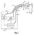
- FIG. 1 is a schematic elevation view of a cold metal transfer welding apparatus embodying the present invention.
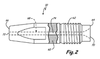
- FIG. 2 is a side partial cut-away view of a contact tip of in the welding apparatus of FIG. 1 .
- cold metal transfer (CMT) welding apparatus 10 of the present invention is useful for welding workpiece 50 that may be made of a cobalt alloy or nickel alloy.
- Welding apparatus 10 includes weld wire 40 that may be made of a cobalt alloy, and contact tip 32 having a substantially copper-free contact surface 74, such as an aluminum surface. When weld wire 40 grinds against contact surface 74, small particles of aluminum can break off instead of small particles of weld-contaminating copper.
- Supply housing 12 of welding apparatus 10 generally supports and surrounds electric power supply 18, wire feeder 20 and gas supply 22.
- a preferably flexible conduit 16 of apparatus 10 is supported by and axially projects outward from supply housing 12 to a distal end that connects to torch 14 of apparatus 10.
- Conduit 16 generally surrounds and protects power cable 38 connected electrically to power supply 18, weld wire 40 fed from wire feeder 20, and gas hose 42 communicating with gas supply 22. Both gas supply 22 and wire feeder 20 may be powered via power supply 18.
- Torch 14 has gas nozzle 24 that has and extends axially along centerline axis C L between opposite ends with the first end connected structurally to the distal end of conduit 16 and the opposite second end carrying nozzle output face 28.
- Contact tip 32 of torch 14 is disposed in cavity 30 defined by and radially inward from nozzle 24.
- Contact tip 32 as well as weld wire 40 are also oriented with centerline axis C L .
- Power cable 38 electrically connects power supply 18 to contact tip 32.
- Power supply 18 provides electrical power to contact tip 32 for welding.
- Power supply 18 also provides power to, and controls operation of, wire feeder 20 and gas supply 22.
- Wire feeder 20 feeds weld wire 40 from a spool (not shown) through conduit 16 and through contact tip 32 such that weld wire tip 48 extends past nozzle output face 28.
- Weld wire 40 is in contact with contact tip 32 such that electrical power transmitted to contact tip 32 is subsequently transmitted to weld wire 40.
- Weld wire 40 can be made of cobalt or cobalt alloys.
- Gas supply 22 is connected to gas nozzle 24 via gas hose 42. Gas supplied from gas supply 22 flows into nozzle cavity 30 and out nozzle output face 28.
- Gas supply 22 can supply inert and semi-inert gases such as argon, helium, carbon dioxide, or mixtures thereof. The gas used can be selected so as to adequately shield weld wire 40 from undesirable contaminants during welding.
- power supply 18 signals wire feeder 20 to feed weld wire 40 toward workpiece 50.
- Power supply 18 also signals gas supply 22 to supply gas to and out of gas nozzle 24.
- Power supply 18 further supplies electrical power to contact tip 32, which transmits that power to weld wire 40.
- weld wire tip 48 becomes sufficiently close to, or in contact with, workpiece 50, electricity can flow from weld wire 40 to workpiece 50.
- Workpiece 50 may be a high strength metal such as cobalt, cobalt alloys, or nickel alloys. In one embodiment, workpiece 50 can be a damaged turbine blade for a gas turbine engine.
- power supply 18 senses a short circuit, it signals wire feeder 20 to retract weld wire 40.
- power supply 18 signals wire feeder 20 to feed weld wire 40 toward workpiece 50 again. This repeats such that weld wire 40 is effectively oscillating axially with respect to contact tip 32.
- electricity arcs from weld wire tip 48 to workpiece 50 and causes a portion of weld wire 40 (also called weld filler) to melt and become deposited as weld metal 52 (also called weld pool) on workpiece 50.
- weld wire 40 also called weld filler
- heat imparted to workpiece 50 decreases. In one embodiment, oscillations may occur about 70 times per second. In other embodiments, oscillating frequency can be less than about 70 times per second so long as heat imparted to workpiece 50 does not exceed an acceptable threshold.
- weld wire 40 maintains electrical, and physical, contact with contact tip 32.
- FIG. 2 is a side partial cut-away view of contact tip 32.
- Contact tip 32 includes electrically conductive metal body 60, connection portion 62, proximal end 64, tip or distal end 66, passage 68, passage inlet 70, passage outlet 72, and contact surface 74.
- Shape of contact tip 32 is defined by a substantially solid metal body 60.
- Metal body 60 may be a substantially copper-free metal such as aluminum, aluminum alloys, titanium, titanium alloys, nickel, nickel alloys, cobalt, cobalt alloys, and stainless steel.
- Contact tip 32 extends from proximal end 64 to tip or distal end 66.
- Connection portion 62 is configured to connect to a welding torch of a CMT welding apparatus such as torch 14 as illustrated in FIG. 1 .
- connection portion 62 carries a threaded surface for threading into torch 14 (shown in FIG.1 ).
- Passage 68 is disposed concentrically to and extending along an axial length of contact tip 32 from passage inlet 70 (at proximal end 64) to passage outlet 72 (at distal end 66).
- passage inlet 70 has a substantially frusto-conical shape for facilitating insertion of weld wire 40 (shown in FIG. 1 ).
- the remainder of passage 68 has a substantially cylindrical shape and is defined by contact surface 74 carried by body 60.
- Contact surface 74 may comprise a substantially copper-free metal such as aluminum, aluminum alloys, titanium, titanium alloys, nickel, nickel alloys, cobalt, cobalt alloys, and stainless steel.
- contact surface 74 may be an aluminum alloy with a relatively high conductivity.
- contact tip 32 is a single-homogeneous piece made of a substantially uniform metal. Consequently, the metal used for connection portion 62 is preferably the same metal as that used for contact surface 74 and is a single, continuous piece therebetween. Using a single continuous piece, as opposed to multiple pieces, may reduce electrical resistance of contact tip 32. In an alternative embodiment, a portion of contact tip 32 may be made of virtually any suitable material so long as contact surface 74 is a substantially copper-free metal.
- the substantially copper-free metal has a sufficiently small quantity of copper (or zero copper) such that performance of weld metal 52 will not be measurably altered due to copper contamination.
- the substantially copper-free metal can contain essentially no copper.
- weld wire 40 As weld wire 40 (shown in FIG. 1 ) is fed through, and oscillates axially in, passage 68, weld wire 40 can rub or grind against contact surface 74. This grinding can wear away contact surface 74, causing particles from contact surface 74 to become deposited in weld metal 52 (shown in FIG. 1 ). In certain circumstances, it may be undesirable for certain metals to contaminate weld metal 52.
- certain portions of gas turbine engines, such as turbine blades can be made from high-strength, heat-tolerant materials such as cobalt, cobalt alloys, and nickel alloys. Using a weld wire of cobalt or cobalt alloys to repair the turbine blade can create a relatively strong, creep-resistant weld.
- weld metal 52 can have a greater susceptibility to creep. This can be especially problematic when using CMT welding apparatus 10 with a cobalt weld wire 40 and a copper contact surface 74.
- the relatively fast oscillation of the relatively hard cobalt weld wire 40 can grind a relatively large quantity of copper off contact surface 74.
- contact tip 32 configured for use with CMT welding apparatus 10 and made from a substantially copper-free metal, such as aluminum, the amount of copper in weld metal 52 can be reduced or eliminated.
- Many alloys, including cobalt alloys already have aluminum in the alloy. Such alloys can tolerate trace additions of aluminum.
- contamination of weld metal 52 can weaken weld metal 52 in ways other than creep. For example, contaminating a relatively ductile alloy with an incompatible metal can make the ductile alloy more brittle.
- contact surface 74 may comprise aluminum or an aluminum alloy. In another embodiment, where weld wire 40 is cobalt or a cobalt alloy and contact surface 74 is desired to be relatively wear-resistant, contact surface 74 can be cobalt, a cobalt alloy, or stainless steel. In another embodiment, where weld wire 40 is nickel or a nickel alloy and contact surface 74 is desired to be relatively wear-resistant, contact surface 74 can be nickel, a nickel alloy, or stainless steel.
- contact surface 74 can be titanium or a titanium alloy.
- Weld wire 40 of a particular titanium alloy can be paired with contact tip 32 of substantially the same titanium alloy.
- contact surface 74 can be other non-copper metals to suit the needs of particular applications.
- the present invention provides numerous benefits and advantages.
- the invention allows for welding using CMT technology while limiting copper contamination in weld metal 52. This can allow use of CMT in various applications that would not otherwise be practical. This can be particularly useful in assembly and repair of gas turbine engines when utilizing a cobalt or cobalt alloy weld wire 40 in a repair welding process.
- Using a substantially copper-free contact surface 74 allows one to create welds with a reduced propensity to creep.
- Using CMT allows for welding with less warpage in workpiece 50 due to welding heat.
Landscapes
- Engineering & Computer Science (AREA)
- Mechanical Engineering (AREA)
- Physics & Mathematics (AREA)
- Plasma & Fusion (AREA)
- General Engineering & Computer Science (AREA)
- Chemical & Material Sciences (AREA)
- Materials Engineering (AREA)
- Arc Welding In General (AREA)
Abstract
Description
- The present invention relates to an arc welding apparatus, and in particular, to a cold metal transfer (CMT) welding apparatus and method of operation.
- Gas metal arc welding (GMAW), commonly referred to as metal inert gas (MIG) welding or metal active gas (MAG) welding, is a welding process in which a consumable weld wire and a shielding gas are fed through a welding torch. There are many types of GMAW that can be used in various situations. Typically, the weld wire is fed though a contact tip made of copper or a copper alloy in the welding torch. The contact tip guides the weld wire and also provides a continuing electrical connection from a power supply to the weld wire as the weld wire is fed. The weld wire is held near or in contact with a metal welding surface such that electricity can arc between the weld wire and the surface. The arc causes a tip of the weld wire to liquefy and is subsequently applied to the welding surface. Typically, an inert or semi-inert gas is blown over the weld wire to limit contaminants near the weld. While GMAW is a useful welding technique, it can heat the welding surface to temperatures that cause undesirable material changes, such as hardening and warpage.
- GMAW cold metal transfer (CMT) is a welding technique that reduces heat created on the welding surface. CMT is based on a deliberate and systematic activation and deactivation of the heating arc so as to systematically heat and cool the weld wire while bringing the wire into and out of contact with the weld pool at a rapid frequency. This is performed by axially oscillating the weld wire forward and backward through the copper contact tip with a frequency of up to 70 times per second. Unfortunately, the grinding contact between the weld wire and the contact tip can wear away the contact tip, especially if the weld wire is a harder material than the contact tip. This wearing away can cause material worn from the contact tip to be deposited on the weld wire or blown into the weld.
- According to the present invention, a cold metal transfer (CMT) contact tip has a substantially copper-free contact surface defining a wire passage. The CMT contact tip is used with a CMT welding apparatus having a weld wire and a wire feeder for feeding and oscillating the weld wire forward and backward through the wire passage where the weld wire shares a concentric axis with the wire passage.
- In another embodiment, a CMT welding apparatus includes a CMT contact tip, a weld wire, and a CMT wire feeder. The CMT contact tip has a contact surface that is a substantially copper-free metal. The weld wire is in physical contact with the contact surface. The CMT wire feeder is constructed and arranged to feed the weld wire through the CMT contact tip with an axially oscillating motion with respect to a centerline axis of the CMT contact tip.
- Another embodiment includes a method for welding a workpiece. The method includes the steps of installing a CMT contact tip having a substantially copper-free metal contact surface into a CMT welding device, feeding a weld wire through the CMT contact tip such that the weld wire axially oscillates along a centerline axis of the CMT contact tip and in contact with the contact surface, and depositing material from the weld wire on the workpiece to form a substantially copper-free weld.
-
FIG. 1 is a schematic elevation view of a cold metal transfer welding apparatus embodying the present invention. -
FIG. 2 is a side partial cut-away view of a contact tip of in the welding apparatus ofFIG. 1 . - Referring to
FIGs 1 and2 , cold metal transfer (CMT)welding apparatus 10 of the present invention is useful forwelding workpiece 50 that may be made of a cobalt alloy or nickel alloy.Welding apparatus 10 includesweld wire 40 that may be made of a cobalt alloy, andcontact tip 32 having a substantially copper-free contact surface 74, such as an aluminum surface. When weld wire 40 grinds againstcontact surface 74, small particles of aluminum can break off instead of small particles of weld-contaminating copper. -
Supply housing 12 ofwelding apparatus 10 generally supports and surroundselectric power supply 18,wire feeder 20 andgas supply 22. A preferablyflexible conduit 16 ofapparatus 10 is supported by and axially projects outward fromsupply housing 12 to a distal end that connects totorch 14 ofapparatus 10.Conduit 16 generally surrounds and protectspower cable 38 connected electrically topower supply 18,weld wire 40 fed fromwire feeder 20, andgas hose 42 communicating withgas supply 22. Bothgas supply 22 andwire feeder 20 may be powered viapower supply 18. - Torch 14 has
gas nozzle 24 that has and extends axially along centerline axis CL between opposite ends with the first end connected structurally to the distal end ofconduit 16 and the opposite second end carryingnozzle output face 28. Contacttip 32 oftorch 14 is disposed incavity 30 defined by and radially inward fromnozzle 24. Contacttip 32 as well asweld wire 40 are also oriented with centerline axis CL. -
Power cable 38 electrically connectspower supply 18 to contacttip 32.Power supply 18 provides electrical power to contacttip 32 forwelding. Power supply 18 also provides power to, and controls operation of,wire feeder 20 andgas supply 22.Wire feeder 20feeds weld wire 40 from a spool (not shown) throughconduit 16 and throughcontact tip 32 such thatweld wire tip 48 extends pastnozzle output face 28.Weld wire 40 is in contact withcontact tip 32 such that electrical power transmitted tocontact tip 32 is subsequently transmitted toweld wire 40.Weld wire 40 can be made of cobalt or cobalt alloys.Gas supply 22 is connected togas nozzle 24 viagas hose 42. Gas supplied fromgas supply 22 flows intonozzle cavity 30 and outnozzle output face 28.Gas supply 22 can supply inert and semi-inert gases such as argon, helium, carbon dioxide, or mixtures thereof. The gas used can be selected so as to adequately shieldweld wire 40 from undesirable contaminants during welding. - In operation,
power supply 18signals wire feeder 20 to feedweld wire 40 towardworkpiece 50.Power supply 18 also signalsgas supply 22 to supply gas to and out ofgas nozzle 24.Power supply 18 further supplies electrical power to contacttip 32, which transmits that power to weldwire 40. Whenweld wire tip 48 becomes sufficiently close to, or in contact with,workpiece 50, electricity can flow fromweld wire 40 toworkpiece 50.Workpiece 50 may be a high strength metal such as cobalt, cobalt alloys, or nickel alloys. In one embodiment,workpiece 50 can be a damaged turbine blade for a gas turbine engine. When power supply 18 senses a short circuit, it signalswire feeder 20 to retractweld wire 40. After a brief retraction,power supply 18signals wire feeder 20 to feedweld wire 40 towardworkpiece 50 again. This repeats such thatweld wire 40 is effectively oscillating axially with respect tocontact tip 32. With each oscillation, electricity arcs fromweld wire tip 48 toworkpiece 50 and causes a portion of weld wire 40 (also called weld filler) to melt and become deposited as weld metal 52 (also called weld pool) onworkpiece 50. As oscillating frequency increases, heat imparted toworkpiece 50 decreases. In one embodiment, oscillations may occur about 70 times per second. In other embodiments, oscillating frequency can be less than about 70 times per second so long as heat imparted toworkpiece 50 does not exceed an acceptable threshold. During these oscillations,weld wire 40 maintains electrical, and physical, contact withcontact tip 32. -
FIG. 2 is a side partial cut-away view ofcontact tip 32.Contact tip 32 includes electricallyconductive metal body 60,connection portion 62,proximal end 64, tip ordistal end 66,passage 68,passage inlet 70,passage outlet 72, andcontact surface 74. Shape ofcontact tip 32 is defined by a substantiallysolid metal body 60.Metal body 60 may be a substantially copper-free metal such as aluminum, aluminum alloys, titanium, titanium alloys, nickel, nickel alloys, cobalt, cobalt alloys, and stainless steel.Contact tip 32 extends fromproximal end 64 to tip ordistal end 66.Connection portion 62 is configured to connect to a welding torch of a CMT welding apparatus such astorch 14 as illustrated inFIG. 1 . In the illustrated embodiment,connection portion 62 carries a threaded surface for threading into torch 14 (shown inFIG.1 ). -
Passage 68 is disposed concentrically to and extending along an axial length ofcontact tip 32 from passage inlet 70 (at proximal end 64) to passage outlet 72 (at distal end 66). In the illustrated embodiment,passage inlet 70 has a substantially frusto-conical shape for facilitating insertion of weld wire 40 (shown inFIG. 1 ). The remainder ofpassage 68 has a substantially cylindrical shape and is defined bycontact surface 74 carried bybody 60.Contact surface 74 may comprise a substantially copper-free metal such as aluminum, aluminum alloys, titanium, titanium alloys, nickel, nickel alloys, cobalt, cobalt alloys, and stainless steel. In one embodiment,contact surface 74 may be an aluminum alloy with a relatively high conductivity. In the illustrated embodiment,contact tip 32 is a single-homogeneous piece made of a substantially uniform metal. Consequently, the metal used forconnection portion 62 is preferably the same metal as that used forcontact surface 74 and is a single, continuous piece therebetween. Using a single continuous piece, as opposed to multiple pieces, may reduce electrical resistance ofcontact tip 32. In an alternative embodiment, a portion ofcontact tip 32 may be made of virtually any suitable material so long ascontact surface 74 is a substantially copper-free metal. The substantially copper-free metal has a sufficiently small quantity of copper (or zero copper) such that performance ofweld metal 52 will not be measurably altered due to copper contamination. The substantially copper-free metal can contain essentially no copper. - As weld wire 40 (shown in
FIG. 1 ) is fed through, and oscillates axially in,passage 68,weld wire 40 can rub or grind againstcontact surface 74. This grinding can wear awaycontact surface 74, causing particles fromcontact surface 74 to become deposited in weld metal 52 (shown inFIG. 1 ). In certain circumstances, it may be undesirable for certain metals to contaminateweld metal 52. For example, certain portions of gas turbine engines, such as turbine blades, can be made from high-strength, heat-tolerant materials such as cobalt, cobalt alloys, and nickel alloys. Using a weld wire of cobalt or cobalt alloys to repair the turbine blade can create a relatively strong, creep-resistant weld. However, ifweld metal 52 is contaminated with copper,weld metal 52 can have a greater susceptibility to creep. This can be especially problematic when usingCMT welding apparatus 10 with acobalt weld wire 40 and acopper contact surface 74. The relatively fast oscillation of the relatively hardcobalt weld wire 40 can grind a relatively large quantity of copper offcontact surface 74. By usingcontact tip 32 configured for use withCMT welding apparatus 10 and made from a substantially copper-free metal, such as aluminum, the amount of copper inweld metal 52 can be reduced or eliminated. Many alloys, including cobalt alloys, already have aluminum in the alloy. Such alloys can tolerate trace additions of aluminum. In some applications, contamination ofweld metal 52 can weakenweld metal 52 in ways other than creep. For example, contaminating a relatively ductile alloy with an incompatible metal can make the ductile alloy more brittle. - Selection of the substantially copper-free metal can depend on the application and on design preferences. In one embodiment, where
weld wire 40 comprises cobalt or a cobalt alloy andcontact surface 74 is desired to have a relatively low electrical resistance,contact surface 74 may comprise aluminum or an aluminum alloy. In another embodiment, whereweld wire 40 is cobalt or a cobalt alloy andcontact surface 74 is desired to be relatively wear-resistant,contact surface 74 can be cobalt, a cobalt alloy, or stainless steel. In another embodiment, whereweld wire 40 is nickel or a nickel alloy andcontact surface 74 is desired to be relatively wear-resistant,contact surface 74 can be nickel, a nickel alloy, or stainless steel. In yet another embodiment, whereweld wire 40 is titanium or a titanium alloy,contact surface 74 can be titanium or a titanium alloy.Weld wire 40 of a particular titanium alloy can be paired withcontact tip 32 of substantially the same titanium alloy. In still other embodiments,contact surface 74 can be other non-copper metals to suit the needs of particular applications. - It will be recognized that the present invention provides numerous benefits and advantages. For example, the invention allows for welding using CMT technology while limiting copper contamination in
weld metal 52. This can allow use of CMT in various applications that would not otherwise be practical. This can be particularly useful in assembly and repair of gas turbine engines when utilizing a cobalt or cobaltalloy weld wire 40 in a repair welding process. Using a substantially copper-free contact surface 74 allows one to create welds with a reduced propensity to creep. Using CMT allows for welding with less warpage inworkpiece 50 due to welding heat. - While the invention has been described with reference to an exemplary embodiment, it will be understood by those skilled in the art that various changes may be made and equivalents may be substituted for elements thereof without departing from the scope of the invention. In addition, many modifications may be made to adapt a particular situation or material to the teachings of the invention without departing from the essential scope thereof. Therefore, it is intended that the invention not be limited to the particular embodiment disclosed, but that the invention will include all embodiments falling within the scope of the appended claims. For example, use of
welding apparatus 10 is not limited to assembly and repair of gas turbine engines, rather, can be used in virtually any suitable welding project that can benefit from its use. Additionally, the shape ofcontact tip 32 need not be limited to that illustrated inFIG. 2 so long as the shape is suitable for use in a cold metal transfer welding apparatus.
Claims (15)
- A cold metal transfer (CMT) contact tip (32) for use with a CMT welding apparatus (10) of the kind having a wire feeder (20) for feeding and oscillating a weld wire (40) forward and backward through and sharing a concentric axis with a wire passage (68) in the CMT contact tip, the CMT contact tip comprising:a substantially copper-free contact surface (74) defining the wire passage.
- The CMT contact tip of claim 1, wherein the CMT contact tip (32) is a homogeneous, single-piece, metal body (60).
- The CMT contact tip of claim 1 or 2, wherein the contact surface (74) is stainless steel; or wherein the contact surface is aluminum or an aluminum alloy; or the contact surface is titanium or a titanium alloy.
- The CMT contact tip of claim 1 or 2 wherein the contact surface (74) is nickel or a nickel alloy.
- The CMT contact tip of claim 1 or 2 wherein the contact surface (74) is cobalt or a cobalt alloy.
- A cold metal transfer (CMT) welding apparatus (10), comprising:a CMT contact tip (32) having a contact surface (74) that is a substantially copper-free metal;a weld wire (40) in physical contact with the contact surface; anda CMT wire feeder (20) constructed and arranged to feed the weld wire through the CMT contact tip with an axially oscillating motion with respect to a centerline axis of the CMT contact tip.
- The CMT welding apparatus of claim 6 wherein the CMT contact tip is as claimed in claim 1 or 2.
- The CMT welding apparatus of claim 6 or 7, wherein the weld wire (40) is cobalt or a cobalt alloy.
- The CMT welding apparatus of claim 6, 7 or 8 wherein the weld wire (40) is substantially the same copper-free metal as that selected for the contact surface (74).
- The CMT welding apparatus of claim 6, 7, 8 or 9 wherein the contact surface (74) is the material mentioned in any one of claims 3 to 5.
- A method for welding a workpiece (50), the method comprising the steps of:installing a cold metal transfer (CMT) contact tip (32) having a substantially copper-free metal contact surface (74) into a CMT welding device (10);feeding a weld wire (40) through the CMT contact tip such that the weld wire axially oscillates along a centerline axis of the CMT contact tip and in contact with the contact surface; anddepositing material from the weld wire on the workpiece to form a substantially copper-free weld.
- The method of claim 11, wherein the weld wire (40) is a metal selected from the group consisting of cobalt and cobalt alloys.
- The method of claim 11 or 12, wherein the workpiece (50) is a damaged turbine blade for a gas turbine engine.
- The method of claim 11, 12 or 13, wherein the workpiece (50) is cobalt, a cobalt alloy, or a nickel alloy.
- The method of claim 11, 12, 13 or 14, wherein the weld wire oscillates with respect to the CMT contact tip without the CMT contact tip depositing copper on the weld wire; and preferably wherein the weld wire oscillates axially with respect to the CMT contact tip about 70 times per second during feeding.
Applications Claiming Priority (1)
| Application Number | Priority Date | Filing Date | Title |
|---|---|---|---|
| US12/398,748 US9321116B2 (en) | 2009-03-05 | 2009-03-05 | Cold metal transfer gas metal arc welding apparatus and method of operation |
Publications (3)
| Publication Number | Publication Date |
|---|---|
| EP2226147A2 true EP2226147A2 (en) | 2010-09-08 |
| EP2226147A3 EP2226147A3 (en) | 2010-10-27 |
| EP2226147B1 EP2226147B1 (en) | 2015-04-15 |
Family
ID=42312657
Family Applications (1)
| Application Number | Title | Priority Date | Filing Date |
|---|---|---|---|
| EP10250010.5A Not-in-force EP2226147B1 (en) | 2009-03-05 | 2010-01-06 | Cold metal transfer gas metal arc welding apparatus and method of operation |
Country Status (3)
| Country | Link |
|---|---|
| US (1) | US9321116B2 (en) |
| EP (1) | EP2226147B1 (en) |
| SG (2) | SG10201402861WA (en) |
Cited By (5)
| Publication number | Priority date | Publication date | Assignee | Title |
|---|---|---|---|---|
| CN102133677A (en) * | 2011-01-28 | 2011-07-27 | 西安誉丰通号科技有限公司 | Steel rail surface modification antirust welding device and rail surface fusing modification method |
| FR2982782A1 (en) * | 2011-11-21 | 2013-05-24 | Snecma | PROCESS FOR THE REPAIR OF METAL TURBOMACHINE PARTS MADE OF NICKEL OR COBALT-BASED SUPERALLIATION USING A MIG PROCESS WITH CURRENT AND PULSED DELIVERY WIRE |
| WO2013049456A3 (en) * | 2011-09-30 | 2013-06-13 | General Electric Company | A method of repairing rotating machine components |
| WO2015086194A1 (en) * | 2013-12-10 | 2015-06-18 | Siemens Aktiengesellschaft | Oscillating welding method |
| CN109590668A (en) * | 2019-01-07 | 2019-04-09 | 浙江翰德圣智能再制造技术有限公司 | A kind of steam turbine cylinder sealing surface renovation technique |
Families Citing this family (14)
| Publication number | Priority date | Publication date | Assignee | Title |
|---|---|---|---|---|
| EP2542373B1 (en) * | 2010-03-02 | 2020-11-25 | Velocys, Inc. | Welded, laminated apparatus, methods of making, and methods of using the apparatus |
| US20120294729A1 (en) * | 2011-05-16 | 2012-11-22 | General Electric Company | Cold metal transfer hardfacing of buckets |
| CN103801799B (en) | 2012-11-12 | 2017-11-21 | 通用电气公司 | The revolving meber for manufacturing the method for revolving meber and being manufactured with this method |
| US9393644B2 (en) * | 2013-01-31 | 2016-07-19 | Siemens Energy, Inc. | Cladding of alloys using flux and metal powder cored feed material |
| EP3736073B1 (en) * | 2013-02-28 | 2025-12-10 | RTX Corporation | Method for repairing an aerospace component |
| CN105555455B (en) | 2013-04-19 | 2018-10-26 | 麦格纳国际公司 | The engagement of dissimilar material |
| EP2808117B8 (en) * | 2013-05-28 | 2016-06-15 | MAGNA STEYR Fahrzeugtechnik AG & Co KG | Method of manufacturing a welded connection between a high strengh aluminium part containing copper and another part using the CMT welding process |
| US20140367366A1 (en) * | 2013-06-14 | 2014-12-18 | Hobart Brothers Company | Systems and methods of conditioning an air flow for a welding environment |
| CA2936412A1 (en) * | 2014-02-11 | 2015-08-20 | Magna International Inc. | Method of joining dissimilar materials |
| WO2017068752A1 (en) * | 2015-10-23 | 2017-04-27 | パナソニックIpマネジメント株式会社 | Welding torch |
| EP3165314A1 (en) * | 2015-11-06 | 2017-05-10 | Siegfried Plasch | Overlay welding method |
| CN109023191A (en) * | 2017-06-12 | 2018-12-18 | 天津大学 | A method of improving aluminium alloy CMT plumb joint wearability |
| CN108941814A (en) * | 2018-07-04 | 2018-12-07 | 广州科奥版权服务有限公司 | The device of steel aluminum dissimilar metal lap joint is prepared using CMT technology |
| CN110142576A (en) * | 2019-06-21 | 2019-08-20 | 燕山大学 | A CMT-based Remanufacturing Method of Hydraulic Support Cylinder |
Citations (2)
| Publication number | Priority date | Publication date | Assignee | Title |
|---|---|---|---|---|
| GB2239204A (en) | 1989-12-21 | 1991-06-26 | Toyota Motor Co Ltd | Contact tip for arc welding |
| WO2006125234A1 (en) | 2005-05-24 | 2006-11-30 | Fronius International Gmbh | Cold metal transfer welding process and welding installation |
Family Cites Families (25)
| Publication number | Priority date | Publication date | Assignee | Title |
|---|---|---|---|---|
| US3056018A (en) | 1960-11-14 | 1962-09-25 | Weltronic Co | Welding apparatus |
| GB1583070A (en) * | 1977-08-03 | 1981-01-21 | Alberta Res Council | Arc welding and welding apparatus therefor |
| JPS57185999A (en) * | 1981-05-09 | 1982-11-16 | Kazumasa Wada | Improvement of contact tip of welder |
| US4726104A (en) | 1986-11-20 | 1988-02-23 | United Technologies Corporation | Methods for weld repairing hollow, air cooled turbine blades and vanes |
| US4937428A (en) | 1988-01-14 | 1990-06-26 | Matsushita Electric Industrial Co., Ltd. | Consumable electrode type arc welding contact tip |
| FR2684321B1 (en) * | 1991-11-29 | 1994-03-11 | Chpo Ardel Sa | ARC WELDING / RECHARGING PROCESS AND IMPLEMENTATION DEVICE. |
| SE9401727D0 (en) * | 1994-05-18 | 1994-05-18 | Astra Ab | New compounds I |
| DE19507472C2 (en) | 1995-03-03 | 1999-09-02 | Electro Chem Eng Gmbh | Gas or current nozzle of an inert gas welding system |
| KR100449568B1 (en) | 1995-10-03 | 2004-11-16 | 가부시키가이샤 에스엠케이 | Contact tip for welding |
| US5760373A (en) | 1995-12-27 | 1998-06-02 | Miller Electric Manufacturing Company | Enhanced contact area quick release mig gun tip |
| US5686001A (en) | 1996-01-16 | 1997-11-11 | United Technologies Corporation | Variable polarity arc technology for the repair of coated articles |
| US6127651A (en) * | 1996-04-29 | 2000-10-03 | Westinghouse Electric Company Llc | Welding apparatus and method |
| US5806751A (en) | 1996-10-17 | 1998-09-15 | United Technologies Corporation | Method of repairing metallic alloy articles, such as gas turbine engine components |
| JP4676698B2 (en) * | 2001-11-07 | 2011-04-27 | エムアイジー ファースト プロプライアティー リミテッド | Improved consumable electrode arc welding |
| US6742698B2 (en) | 2002-06-10 | 2004-06-01 | United Technologies Corporation | Refractory metal backing material for weld repair |
| CA2452112A1 (en) * | 2002-12-09 | 2004-06-09 | Mold-Masters Limited | Nozzle tip and seal |
| EP1677940B1 (en) | 2003-10-23 | 2013-11-27 | Fronius International GmbH | Method for controlling and/or adjusting a welding process and welding device for carrying out a welding process |
| US7229523B2 (en) * | 2005-03-31 | 2007-06-12 | Xerox Corporation | Treatment for ultrasonic welding |
| US20060237411A1 (en) * | 2005-04-22 | 2006-10-26 | Mendez Patricio F | Gas metal arc welding methods and apparatus |
| US7966707B2 (en) | 2005-05-06 | 2011-06-28 | United Technologies Corporation | Method for repairing superalloy components using inserts |
| KR100673544B1 (en) * | 2005-08-22 | 2007-01-24 | 고려용접봉 주식회사 | Unpainted Wire for Gas Shield Arc Welding |
| EP1797985A1 (en) * | 2005-12-19 | 2007-06-20 | Siemens Aktiengesellschaft | Method and device for welding |
| US7498543B2 (en) | 2006-03-22 | 2009-03-03 | Gm Global Technology Operations, Inc. | Method for joining or repairing metal surface parts |
| AT503468B1 (en) * | 2006-04-04 | 2008-04-15 | Fronius Int Gmbh | PROCESS FOR CLEANING A CONTACT TUBE OF A WELDING BURNER |
| DE202007003720U1 (en) | 2007-03-07 | 2007-05-31 | Tbi Industries Gmbh | Current nozzle for a welding torch for MIG / MAG welding processes |
-
2009
- 2009-03-05 US US12/398,748 patent/US9321116B2/en not_active Expired - Fee Related
-
2010
- 2010-01-06 EP EP10250010.5A patent/EP2226147B1/en not_active Not-in-force
- 2010-01-15 SG SG10201402861WA patent/SG10201402861WA/en unknown
- 2010-01-15 SG SG201000290-5A patent/SG164314A1/en unknown
Patent Citations (2)
| Publication number | Priority date | Publication date | Assignee | Title |
|---|---|---|---|---|
| GB2239204A (en) | 1989-12-21 | 1991-06-26 | Toyota Motor Co Ltd | Contact tip for arc welding |
| WO2006125234A1 (en) | 2005-05-24 | 2006-11-30 | Fronius International Gmbh | Cold metal transfer welding process and welding installation |
Cited By (6)
| Publication number | Priority date | Publication date | Assignee | Title |
|---|---|---|---|---|
| CN102133677A (en) * | 2011-01-28 | 2011-07-27 | 西安誉丰通号科技有限公司 | Steel rail surface modification antirust welding device and rail surface fusing modification method |
| WO2013049456A3 (en) * | 2011-09-30 | 2013-06-13 | General Electric Company | A method of repairing rotating machine components |
| CN104010762A (en) * | 2011-09-30 | 2014-08-27 | 通用电气公司 | Methods of Repairing Rotating Machinery Components |
| FR2982782A1 (en) * | 2011-11-21 | 2013-05-24 | Snecma | PROCESS FOR THE REPAIR OF METAL TURBOMACHINE PARTS MADE OF NICKEL OR COBALT-BASED SUPERALLIATION USING A MIG PROCESS WITH CURRENT AND PULSED DELIVERY WIRE |
| WO2015086194A1 (en) * | 2013-12-10 | 2015-06-18 | Siemens Aktiengesellschaft | Oscillating welding method |
| CN109590668A (en) * | 2019-01-07 | 2019-04-09 | 浙江翰德圣智能再制造技术有限公司 | A kind of steam turbine cylinder sealing surface renovation technique |
Also Published As
| Publication number | Publication date |
|---|---|
| EP2226147B1 (en) | 2015-04-15 |
| SG164314A1 (en) | 2010-09-29 |
| EP2226147A3 (en) | 2010-10-27 |
| US9321116B2 (en) | 2016-04-26 |
| SG10201402861WA (en) | 2014-07-30 |
| US20100224609A1 (en) | 2010-09-09 |
Similar Documents
| Publication | Publication Date | Title |
|---|---|---|
| US9321116B2 (en) | Cold metal transfer gas metal arc welding apparatus and method of operation | |
| EP2454046B1 (en) | Contact tip with refractory material reinforced copper composite ; welding torch with such contact tip | |
| CN101331000B (en) | Welding torches and end pieces and conductive tubes for welding torches | |
| CN103313816B (en) | Welding head with movable electrode and corresponding welding method | |
| US8357877B2 (en) | Front consumables for pulse GMAW torches | |
| US20090107958A1 (en) | Torch and Contact Tip for Gas Metal Arc Welding | |
| US9193005B2 (en) | Contact tip with contoured bore | |
| CN111386168A (en) | Welding assembly for a welding torch with two contact tips and a cooling body for cooling and conducting electric current | |
| JP2014176890A (en) | Welding torch and arc-welding system | |
| CN110891724B (en) | Welding gun | |
| KR20140114837A (en) | Contact tip for use in gas metal-arc welding | |
| CN102448654A (en) | Welding contact tip with diamond and welding gun with the welding contact tip | |
| WO2009034460A2 (en) | Method and apparatus of welding with electrical stickout | |
| US20080061050A1 (en) | Tungsten-copper welding tip | |
| JP4896847B2 (en) | Forced pressure feeding chip assembly and forced pressure feeding torch | |
| US5900167A (en) | Narrow prep MIG welding | |
| KR101669406B1 (en) | A Ceramic Welding Contact Tip prevented burn back | |
| US7297900B2 (en) | Bypass weld torch | |
| CN118369178A (en) | Welding torch | |
| JP4391835B2 (en) | Collet body and TIG welding torch | |
| JPH04294870A (en) | Feeding chip of torch for arc welding | |
| JP3136437U (en) | Shield nozzle of gas shielded arc welding torch | |
| KR20200119012A (en) | Tungsten electrode for TIG welding | |
| Morgan et al. | Internal wire guide for GTAW welding | |
| JPS6245481A (en) | Torch for welding |
Legal Events
| Date | Code | Title | Description |
|---|---|---|---|
| PUAI | Public reference made under article 153(3) epc to a published international application that has entered the european phase |
Free format text: ORIGINAL CODE: 0009012 |
|
| AK | Designated contracting states |
Kind code of ref document: A2 Designated state(s): AT BE BG CH CY CZ DE DK EE ES FI FR GB GR HR HU IE IS IT LI LT LU LV MC MK MT NL NO PL PT RO SE SI SK SM TR |
|
| AX | Request for extension of the european patent |
Extension state: AL BA RS |
|
| PUAL | Search report despatched |
Free format text: ORIGINAL CODE: 0009013 |
|
| AK | Designated contracting states |
Kind code of ref document: A3 Designated state(s): AT BE BG CH CY CZ DE DK EE ES FI FR GB GR HR HU IE IS IT LI LT LU LV MC MK MT NL NO PL PT RO SE SI SK SM TR |
|
| AX | Request for extension of the european patent |
Extension state: AL BA RS |
|
| RIC1 | Information provided on ipc code assigned before grant |
Ipc: F01D 5/00 20060101ALI20100917BHEP Ipc: B23P 6/00 20060101ALI20100917BHEP Ipc: B23K 9/28 20060101ALI20100917BHEP Ipc: B23K 9/23 20060101ALI20100917BHEP Ipc: B23K 9/173 20060101ALI20100917BHEP Ipc: B23K 9/022 20060101AFI20100712BHEP |
|
| 17P | Request for examination filed |
Effective date: 20110427 |
|
| 17Q | First examination report despatched |
Effective date: 20121107 |
|
| GRAP | Despatch of communication of intention to grant a patent |
Free format text: ORIGINAL CODE: EPIDOSNIGR1 |
|
| INTG | Intention to grant announced |
Effective date: 20141126 |
|
| GRAS | Grant fee paid |
Free format text: ORIGINAL CODE: EPIDOSNIGR3 |
|
| GRAA | (expected) grant |
Free format text: ORIGINAL CODE: 0009210 |
|
| AK | Designated contracting states |
Kind code of ref document: B1 Designated state(s): AT BE BG CH CY CZ DE DK EE ES FI FR GB GR HR HU IE IS IT LI LT LU LV MC MK MT NL NO PL PT RO SE SI SK SM TR |
|
| REG | Reference to a national code |
Ref country code: GB Ref legal event code: FG4D Ref country code: CH Ref legal event code: EP |
|
| REG | Reference to a national code |
Ref country code: IE Ref legal event code: FG4D |
|
| REG | Reference to a national code |
Ref country code: AT Ref legal event code: REF Ref document number: 721668 Country of ref document: AT Kind code of ref document: T Effective date: 20150515 |
|
| REG | Reference to a national code |
Ref country code: DE Ref legal event code: R096 Ref document number: 602010023930 Country of ref document: DE Effective date: 20150528 |
|
| REG | Reference to a national code |
Ref country code: NL Ref legal event code: VDEP Effective date: 20150415 |
|
| REG | Reference to a national code |
Ref country code: AT Ref legal event code: MK05 Ref document number: 721668 Country of ref document: AT Kind code of ref document: T Effective date: 20150415 |
|
| REG | Reference to a national code |
Ref country code: LT Ref legal event code: MG4D |
|
| PG25 | Lapsed in a contracting state [announced via postgrant information from national office to epo] |
Ref country code: NL Free format text: LAPSE BECAUSE OF FAILURE TO SUBMIT A TRANSLATION OF THE DESCRIPTION OR TO PAY THE FEE WITHIN THE PRESCRIBED TIME-LIMIT Effective date: 20150415 |
|
| PG25 | Lapsed in a contracting state [announced via postgrant information from national office to epo] |
Ref country code: PT Free format text: LAPSE BECAUSE OF FAILURE TO SUBMIT A TRANSLATION OF THE DESCRIPTION OR TO PAY THE FEE WITHIN THE PRESCRIBED TIME-LIMIT Effective date: 20150817 Ref country code: LT Free format text: LAPSE BECAUSE OF FAILURE TO SUBMIT A TRANSLATION OF THE DESCRIPTION OR TO PAY THE FEE WITHIN THE PRESCRIBED TIME-LIMIT Effective date: 20150415 Ref country code: NO Free format text: LAPSE BECAUSE OF FAILURE TO SUBMIT A TRANSLATION OF THE DESCRIPTION OR TO PAY THE FEE WITHIN THE PRESCRIBED TIME-LIMIT Effective date: 20150715 Ref country code: HR Free format text: LAPSE BECAUSE OF FAILURE TO SUBMIT A TRANSLATION OF THE DESCRIPTION OR TO PAY THE FEE WITHIN THE PRESCRIBED TIME-LIMIT Effective date: 20150415 Ref country code: FI Free format text: LAPSE BECAUSE OF FAILURE TO SUBMIT A TRANSLATION OF THE DESCRIPTION OR TO PAY THE FEE WITHIN THE PRESCRIBED TIME-LIMIT Effective date: 20150415 Ref country code: ES Free format text: LAPSE BECAUSE OF FAILURE TO SUBMIT A TRANSLATION OF THE DESCRIPTION OR TO PAY THE FEE WITHIN THE PRESCRIBED TIME-LIMIT Effective date: 20150415 |
|
| PG25 | Lapsed in a contracting state [announced via postgrant information from national office to epo] |
Ref country code: IS Free format text: LAPSE BECAUSE OF FAILURE TO SUBMIT A TRANSLATION OF THE DESCRIPTION OR TO PAY THE FEE WITHIN THE PRESCRIBED TIME-LIMIT Effective date: 20150815 Ref country code: AT Free format text: LAPSE BECAUSE OF FAILURE TO SUBMIT A TRANSLATION OF THE DESCRIPTION OR TO PAY THE FEE WITHIN THE PRESCRIBED TIME-LIMIT Effective date: 20150415 Ref country code: GR Free format text: LAPSE BECAUSE OF FAILURE TO SUBMIT A TRANSLATION OF THE DESCRIPTION OR TO PAY THE FEE WITHIN THE PRESCRIBED TIME-LIMIT Effective date: 20150716 Ref country code: LV Free format text: LAPSE BECAUSE OF FAILURE TO SUBMIT A TRANSLATION OF THE DESCRIPTION OR TO PAY THE FEE WITHIN THE PRESCRIBED TIME-LIMIT Effective date: 20150415 |
|
| REG | Reference to a national code |
Ref country code: FR Ref legal event code: PLFP Year of fee payment: 7 |
|
| REG | Reference to a national code |
Ref country code: DE Ref legal event code: R097 Ref document number: 602010023930 Country of ref document: DE |
|
| PG25 | Lapsed in a contracting state [announced via postgrant information from national office to epo] |
Ref country code: DK Free format text: LAPSE BECAUSE OF FAILURE TO SUBMIT A TRANSLATION OF THE DESCRIPTION OR TO PAY THE FEE WITHIN THE PRESCRIBED TIME-LIMIT Effective date: 20150415 Ref country code: EE Free format text: LAPSE BECAUSE OF FAILURE TO SUBMIT A TRANSLATION OF THE DESCRIPTION OR TO PAY THE FEE WITHIN THE PRESCRIBED TIME-LIMIT Effective date: 20150415 |
|
| PLBE | No opposition filed within time limit |
Free format text: ORIGINAL CODE: 0009261 |
|
| STAA | Information on the status of an ep patent application or granted ep patent |
Free format text: STATUS: NO OPPOSITION FILED WITHIN TIME LIMIT |
|
| PG25 | Lapsed in a contracting state [announced via postgrant information from national office to epo] |
Ref country code: SK Free format text: LAPSE BECAUSE OF FAILURE TO SUBMIT A TRANSLATION OF THE DESCRIPTION OR TO PAY THE FEE WITHIN THE PRESCRIBED TIME-LIMIT Effective date: 20150415 Ref country code: CZ Free format text: LAPSE BECAUSE OF FAILURE TO SUBMIT A TRANSLATION OF THE DESCRIPTION OR TO PAY THE FEE WITHIN THE PRESCRIBED TIME-LIMIT Effective date: 20150415 Ref country code: PL Free format text: LAPSE BECAUSE OF FAILURE TO SUBMIT A TRANSLATION OF THE DESCRIPTION OR TO PAY THE FEE WITHIN THE PRESCRIBED TIME-LIMIT Effective date: 20150415 Ref country code: RO Free format text: LAPSE BECAUSE OF NON-PAYMENT OF DUE FEES Effective date: 20150415 |
|
| 26N | No opposition filed |
Effective date: 20160118 |
|
| PG25 | Lapsed in a contracting state [announced via postgrant information from national office to epo] |
Ref country code: IT Free format text: LAPSE BECAUSE OF FAILURE TO SUBMIT A TRANSLATION OF THE DESCRIPTION OR TO PAY THE FEE WITHIN THE PRESCRIBED TIME-LIMIT Effective date: 20150415 |
|
| PG25 | Lapsed in a contracting state [announced via postgrant information from national office to epo] |
Ref country code: BE Free format text: LAPSE BECAUSE OF NON-PAYMENT OF DUE FEES Effective date: 20160131 Ref country code: SI Free format text: LAPSE BECAUSE OF FAILURE TO SUBMIT A TRANSLATION OF THE DESCRIPTION OR TO PAY THE FEE WITHIN THE PRESCRIBED TIME-LIMIT Effective date: 20150415 |
|
| PG25 | Lapsed in a contracting state [announced via postgrant information from national office to epo] |
Ref country code: BE Free format text: LAPSE BECAUSE OF FAILURE TO SUBMIT A TRANSLATION OF THE DESCRIPTION OR TO PAY THE FEE WITHIN THE PRESCRIBED TIME-LIMIT Effective date: 20150415 Ref country code: LU Free format text: LAPSE BECAUSE OF FAILURE TO SUBMIT A TRANSLATION OF THE DESCRIPTION OR TO PAY THE FEE WITHIN THE PRESCRIBED TIME-LIMIT Effective date: 20160106 |
|
| REG | Reference to a national code |
Ref country code: CH Ref legal event code: PL |
|
| PG25 | Lapsed in a contracting state [announced via postgrant information from national office to epo] |
Ref country code: MC Free format text: LAPSE BECAUSE OF FAILURE TO SUBMIT A TRANSLATION OF THE DESCRIPTION OR TO PAY THE FEE WITHIN THE PRESCRIBED TIME-LIMIT Effective date: 20150415 |
|
| PG25 | Lapsed in a contracting state [announced via postgrant information from national office to epo] |
Ref country code: CH Free format text: LAPSE BECAUSE OF NON-PAYMENT OF DUE FEES Effective date: 20160131 Ref country code: LI Free format text: LAPSE BECAUSE OF NON-PAYMENT OF DUE FEES Effective date: 20160131 |
|
| REG | Reference to a national code |
Ref country code: IE Ref legal event code: MM4A |
|
| REG | Reference to a national code |
Ref country code: FR Ref legal event code: PLFP Year of fee payment: 8 |
|
| PG25 | Lapsed in a contracting state [announced via postgrant information from national office to epo] |
Ref country code: IE Free format text: LAPSE BECAUSE OF NON-PAYMENT OF DUE FEES Effective date: 20160106 |
|
| REG | Reference to a national code |
Ref country code: FR Ref legal event code: CA Effective date: 20170324 |
|
| PG25 | Lapsed in a contracting state [announced via postgrant information from national office to epo] |
Ref country code: SE Free format text: LAPSE BECAUSE OF FAILURE TO SUBMIT A TRANSLATION OF THE DESCRIPTION OR TO PAY THE FEE WITHIN THE PRESCRIBED TIME-LIMIT Effective date: 20150415 |
|
| REG | Reference to a national code |
Ref country code: DE Ref legal event code: R082 Ref document number: 602010023930 Country of ref document: DE Representative=s name: SCHMITT-NILSON SCHRAUD WAIBEL WOHLFROM PATENTA, DE |
|
| REG | Reference to a national code |
Ref country code: DE Ref legal event code: R082 Ref document number: 602010023930 Country of ref document: DE Representative=s name: SCHMITT-NILSON SCHRAUD WAIBEL WOHLFROM PATENTA, DE Ref country code: DE Ref legal event code: R081 Ref document number: 602010023930 Country of ref document: DE Owner name: UNITED TECHNOLOGIES CORP. (N.D.GES.D. STAATES , US Free format text: FORMER OWNER: UNITED TECHNOLOGIES CORP., HARTFORD, CONN., US |
|
| PG25 | Lapsed in a contracting state [announced via postgrant information from national office to epo] |
Ref country code: MT Free format text: LAPSE BECAUSE OF FAILURE TO SUBMIT A TRANSLATION OF THE DESCRIPTION OR TO PAY THE FEE WITHIN THE PRESCRIBED TIME-LIMIT Effective date: 20150415 |
|
| REG | Reference to a national code |
Ref country code: FR Ref legal event code: PLFP Year of fee payment: 9 |
|
| PG25 | Lapsed in a contracting state [announced via postgrant information from national office to epo] |
Ref country code: SM Free format text: LAPSE BECAUSE OF FAILURE TO SUBMIT A TRANSLATION OF THE DESCRIPTION OR TO PAY THE FEE WITHIN THE PRESCRIBED TIME-LIMIT Effective date: 20150415 Ref country code: HU Free format text: LAPSE BECAUSE OF FAILURE TO SUBMIT A TRANSLATION OF THE DESCRIPTION OR TO PAY THE FEE WITHIN THE PRESCRIBED TIME-LIMIT; INVALID AB INITIO Effective date: 20100106 Ref country code: CY Free format text: LAPSE BECAUSE OF FAILURE TO SUBMIT A TRANSLATION OF THE DESCRIPTION OR TO PAY THE FEE WITHIN THE PRESCRIBED TIME-LIMIT Effective date: 20150415 |
|
| PG25 | Lapsed in a contracting state [announced via postgrant information from national office to epo] |
Ref country code: TR Free format text: LAPSE BECAUSE OF FAILURE TO SUBMIT A TRANSLATION OF THE DESCRIPTION OR TO PAY THE FEE WITHIN THE PRESCRIBED TIME-LIMIT Effective date: 20150415 Ref country code: MT Free format text: LAPSE BECAUSE OF FAILURE TO SUBMIT A TRANSLATION OF THE DESCRIPTION OR TO PAY THE FEE WITHIN THE PRESCRIBED TIME-LIMIT Effective date: 20160131 Ref country code: MK Free format text: LAPSE BECAUSE OF FAILURE TO SUBMIT A TRANSLATION OF THE DESCRIPTION OR TO PAY THE FEE WITHIN THE PRESCRIBED TIME-LIMIT Effective date: 20150415 |
|
| PG25 | Lapsed in a contracting state [announced via postgrant information from national office to epo] |
Ref country code: BG Free format text: LAPSE BECAUSE OF FAILURE TO SUBMIT A TRANSLATION OF THE DESCRIPTION OR TO PAY THE FEE WITHIN THE PRESCRIBED TIME-LIMIT Effective date: 20150415 |
|
| REG | Reference to a national code |
Ref country code: DE Ref legal event code: R081 Ref document number: 602010023930 Country of ref document: DE Owner name: RAYTHEON TECHNOLOGIES CORPORATION (N.D.GES.D.S, US Free format text: FORMER OWNER: UNITED TECHNOLOGIES CORP. (N.D.GES.D. STAATES DELAWARE), FARMINGTON, CONN., US |
|
| PGFP | Annual fee paid to national office [announced via postgrant information from national office to epo] |
Ref country code: GB Payment date: 20221221 Year of fee payment: 14 Ref country code: FR Payment date: 20221220 Year of fee payment: 14 |
|
| PGFP | Annual fee paid to national office [announced via postgrant information from national office to epo] |
Ref country code: DE Payment date: 20221220 Year of fee payment: 14 |
|
| REG | Reference to a national code |
Ref country code: DE Ref legal event code: R119 Ref document number: 602010023930 Country of ref document: DE |
|
| GBPC | Gb: european patent ceased through non-payment of renewal fee |
Effective date: 20240106 |
|
| PG25 | Lapsed in a contracting state [announced via postgrant information from national office to epo] |
Ref country code: DE Free format text: LAPSE BECAUSE OF NON-PAYMENT OF DUE FEES Effective date: 20240801 |
|
| PG25 | Lapsed in a contracting state [announced via postgrant information from national office to epo] |
Ref country code: GB Free format text: LAPSE BECAUSE OF NON-PAYMENT OF DUE FEES Effective date: 20240106 |
|
| PG25 | Lapsed in a contracting state [announced via postgrant information from national office to epo] |
Ref country code: FR Free format text: LAPSE BECAUSE OF NON-PAYMENT OF DUE FEES Effective date: 20240131 |
|
| PG25 | Lapsed in a contracting state [announced via postgrant information from national office to epo] |
Ref country code: GB Free format text: LAPSE BECAUSE OF NON-PAYMENT OF DUE FEES Effective date: 20240106 Ref country code: FR Free format text: LAPSE BECAUSE OF NON-PAYMENT OF DUE FEES Effective date: 20240131 Ref country code: DE Free format text: LAPSE BECAUSE OF NON-PAYMENT OF DUE FEES Effective date: 20240801 |