EP2226112A2 - Air Dryer for Electrical Enclosures - Google Patents
Air Dryer for Electrical Enclosures Download PDFInfo
- Publication number
- EP2226112A2 EP2226112A2 EP10154076A EP10154076A EP2226112A2 EP 2226112 A2 EP2226112 A2 EP 2226112A2 EP 10154076 A EP10154076 A EP 10154076A EP 10154076 A EP10154076 A EP 10154076A EP 2226112 A2 EP2226112 A2 EP 2226112A2
- Authority
- EP
- European Patent Office
- Prior art keywords
- end cap
- membrane module
- outlet end
- air dryer
- membrane
- Prior art date
- Legal status (The legal status is an assumption and is not a legal conclusion. Google has not performed a legal analysis and makes no representation as to the accuracy of the status listed.)
- Withdrawn
Links
- 239000012528 membrane Substances 0.000 claims abstract description 101
- 239000000835 fiber Substances 0.000 claims description 14
- 230000001105 regulatory effect Effects 0.000 claims description 4
- 238000011144 upstream manufacturing Methods 0.000 claims description 3
- 238000004891 communication Methods 0.000 claims description 2
- 239000012530 fluid Substances 0.000 claims description 2
- 238000000034 method Methods 0.000 claims description 2
- 230000003716 rejuvenation Effects 0.000 claims 1
- 230000001681 protective effect Effects 0.000 abstract description 2
- 238000004140 cleaning Methods 0.000 description 9
- -1 for example Polymers 0.000 description 8
- 238000001035 drying Methods 0.000 description 5
- XLYOFNOQVPJJNP-UHFFFAOYSA-N water Substances O XLYOFNOQVPJJNP-UHFFFAOYSA-N 0.000 description 5
- 239000012466 permeate Substances 0.000 description 4
- 239000000126 substance Substances 0.000 description 4
- 230000001629 suppression Effects 0.000 description 4
- 238000007605 air drying Methods 0.000 description 3
- 239000000356 contaminant Substances 0.000 description 3
- 239000003599 detergent Substances 0.000 description 3
- 239000002245 particle Substances 0.000 description 3
- 241000894006 Bacteria Species 0.000 description 2
- 230000033228 biological regulation Effects 0.000 description 2
- 230000001276 controlling effect Effects 0.000 description 2
- 239000004952 Polyamide Substances 0.000 description 1
- 239000004642 Polyimide Substances 0.000 description 1
- 238000000429 assembly Methods 0.000 description 1
- 230000000712 assembly Effects 0.000 description 1
- 239000011324 bead Substances 0.000 description 1
- 230000003749 cleanliness Effects 0.000 description 1
- 238000011109 contamination Methods 0.000 description 1
- 238000010586 diagram Methods 0.000 description 1
- 239000003814 drug Substances 0.000 description 1
- 230000003670 easy-to-clean Effects 0.000 description 1
- RTZKZFJDLAIYFH-UHFFFAOYSA-N ether Substances CCOCC RTZKZFJDLAIYFH-UHFFFAOYSA-N 0.000 description 1
- 239000007943 implant Substances 0.000 description 1
- 230000036512 infertility Effects 0.000 description 1
- 238000001764 infiltration Methods 0.000 description 1
- 230000008595 infiltration Effects 0.000 description 1
- 239000000463 material Substances 0.000 description 1
- 229940127554 medical product Drugs 0.000 description 1
- 239000000203 mixture Substances 0.000 description 1
- 229920002492 poly(sulfone) Polymers 0.000 description 1
- 229920002647 polyamide Polymers 0.000 description 1
- 229920001721 polyimide Polymers 0.000 description 1
- 229920000642 polymer Polymers 0.000 description 1
- 229920006380 polyphenylene oxide Polymers 0.000 description 1
- 229920002981 polyvinylidene fluoride Polymers 0.000 description 1
- 238000007789 sealing Methods 0.000 description 1
- 238000013022 venting Methods 0.000 description 1
Images





Classifications
-
- B—PERFORMING OPERATIONS; TRANSPORTING
- B01—PHYSICAL OR CHEMICAL PROCESSES OR APPARATUS IN GENERAL
- B01D—SEPARATION
- B01D63/00—Apparatus in general for separation processes using semi-permeable membranes
- B01D63/02—Hollow fibre modules
-
- B—PERFORMING OPERATIONS; TRANSPORTING
- B01—PHYSICAL OR CHEMICAL PROCESSES OR APPARATUS IN GENERAL
- B01D—SEPARATION
- B01D53/00—Separation of gases or vapours; Recovering vapours of volatile solvents from gases; Chemical or biological purification of waste gases, e.g. engine exhaust gases, smoke, fumes, flue gases, aerosols
- B01D53/22—Separation of gases or vapours; Recovering vapours of volatile solvents from gases; Chemical or biological purification of waste gases, e.g. engine exhaust gases, smoke, fumes, flue gases, aerosols by diffusion
-
- B—PERFORMING OPERATIONS; TRANSPORTING
- B01—PHYSICAL OR CHEMICAL PROCESSES OR APPARATUS IN GENERAL
- B01D—SEPARATION
- B01D53/00—Separation of gases or vapours; Recovering vapours of volatile solvents from gases; Chemical or biological purification of waste gases, e.g. engine exhaust gases, smoke, fumes, flue gases, aerosols
- B01D53/26—Drying gases or vapours
- B01D53/268—Drying gases or vapours by diffusion
-
- B—PERFORMING OPERATIONS; TRANSPORTING
- B01—PHYSICAL OR CHEMICAL PROCESSES OR APPARATUS IN GENERAL
- B01D—SEPARATION
- B01D2257/00—Components to be removed
- B01D2257/80—Water
-
- Y—GENERAL TAGGING OF NEW TECHNOLOGICAL DEVELOPMENTS; GENERAL TAGGING OF CROSS-SECTIONAL TECHNOLOGIES SPANNING OVER SEVERAL SECTIONS OF THE IPC; TECHNICAL SUBJECTS COVERED BY FORMER USPC CROSS-REFERENCE ART COLLECTIONS [XRACs] AND DIGESTS
- Y10—TECHNICAL SUBJECTS COVERED BY FORMER USPC
- Y10T—TECHNICAL SUBJECTS COVERED BY FORMER US CLASSIFICATION
- Y10T29/00—Metal working
- Y10T29/49—Method of mechanical manufacture
- Y10T29/49826—Assembling or joining
Definitions
- the present invention relates generally to membrane gas dryers for drying a stream of gas and, more particularly, to membrane air dryers for drying compressed air.
- food processing plants typically must be cleaned at regular intervals in order to comply with various governmental regulations intended to ensure food safety.
- this entails shutting down at least a portion of the plant and manually cleaning the plant using various detergents.
- the detergents are applied by cleaning personnel via a hose or the like.
- a fixed cleaning system including an array of nozzles may automatically wash down the plant.
- Such dryers are known in the art of compressed gas systems and are devices that remove water from a compressed air system, specifically the water that exists in the vapour phase.
- the performance of such air driers is generally measured by the dewpoint suppression achieved as air passes through the module.
- the dewpoint is the temperature at which moisture will start to condense out of the moist air.
- Dewpoint suppression is the number of degrees the dew point is lowered as the air passes through the drier.
- the dewpoint suppression is a function of the membrane area, feed flow rate, operating pressure and temperature, and sweep fraction.
- Membrane air dryers typically function by contacting one side of a semi-permeable membrane with a pressurized wet feed stream. The membrane preferentially allows water vapour to permeate through it resulting in a drying of the compressed air stream. A portion of the dried gas, commonly referred to as the "sweep", is fed back to contact the other side of the membrane and acts to sweep away the water moisture that has permeated the membrane. The sweep is often controlled by an externally mounted valve or an internal orifice. Such dryers typically employ an external valve or pressure regulator for controlling the flow of compressed air through the dryer.
- An air dryer having an internal orifice designed into an outlet end cap that eliminates the need for external valves or regulators to control the flow of air through the dryer.
- the internal orifice which can be press-fit or threaded into the end cap, provides a consistent and stable outlet flow and dew point. Preset outlet flow and dew point is more user friendly and eliminates the uncertainty associated with having to determine the outlet flow and dew point. This feature is especially advantageous in applications that lack the instruments to measure outlet flow and dew point, such as for example processing plants which are used to prepare foodstuffs. Another benefit is that the orifice size can be easily changed with a wrench thereby changing outlet flow and dew point, if so desired.
- the air dryer since known air dryers are generally not suitable for use in air drying systems of processing plants where they can be exposed to harsh cleaning chemicals and/or can harbour contaminants (for example food particles in a food processing plant) that can encourage bacteria growth and unsanitary conditions, the air dryer includes a protective sleeve in the form of a tubular shroud.
- the tubular shroud shields the membrane module from exposure to cleaning chemicals and provides an exterior surface that is easy to clean and is generally free of cavities for contaminants to accumulate.
- the air dryer also includes an exhaust port for venting the sweep gas at a lower side thereof such that, when mounted, the sweep gas exhaust port can be shielded from infiltration by contaminant particles and/or cleaning chemicals.
- the invention provides a membrane air dryer which comprises a tubular hollow fibre membrane module, a tubular shroud enclosing the hollow fibre membrane module, and an outlet end cap including an outlet end cap body connected to an outlet end of the hollow fibre membrane module, the outlet end cap body having a central aperture fluidly connected with an outlet end of the membrane module, and at least one flow path externally spaced from the aperture and fluidly connected with an external sweep air region formed between the tubular membrane module and the tubular shroud.
- the at least one flow path can be formed by a channel along the exterior surface of the outlet end cap body, and the flow path is defined between the outlet end cap body and shroud.
- the outlet end cap can include an orifice for regulating flow through the aperture from the outlet end of the hollow fibre membrane module.
- the outlet end cap can further include an orifice body fixed within the central aperture of the end cap body, and defining the orifice.
- the orifice body can be press-fit or threadably received within the central aperture.
- the outlet end cap can be removably connected to the membrane module.
- the membrane air dryer can also include an inlet end cap including an inlet end cap body connected to an inlet end of the hollow fibre membrane module.
- a watertight seal can be provided between the inlet end cap and the tubular shroud.
- the tubular shroud can be captured between the inlet end cap and the outlet end cap.
- the invention provides a membrane air dryer which comprises a tubular hollow fibre membrane module having an inlet, an outlet and a bundle of hollow fibres supported therein, at least one of the hollow fibres having an interior passageway for the flow of air through the module from an upstream end near the inlet to a downstream end near the outlet, the hollow fibres having interstitial spaces therebetween for the flow of a sweep gas, and an outlet end cap.
- the outlet end cap includes an end cap body connected to the outlet end of the membrane module, the end cap body having a central aperture fluidly connected with the outlet of the membrane module and having an orifice for regulating flow through the aperture from the outlet end of the membrane module.
- the orifice can be included in an orifice body fixed within the central aperture of the end cap body.
- the orifice body can be press-fit or threadedly received within the central aperture.
- the outlet end cap can be removably connected to the membrane module.
- the membrane air dryer can further include a passageway for supplying a sweep gas to interstitial spaces between the hollow fibres, the passageway fluidly connecting the outlet of the membrane module to the interstitial spaces such that a portion of the air flowing through the hollow fibres can be utilized as sweep gas to remove moisture from the interstitial spaces.
- a sweep gas inlet orifice can be provided for controlling the flow of sweep gas through the passageway to the interstitial spaces.
- An inlet end cap can also be provided including an end cap body attached to the inlet end of the membrane module, the inlet end cap and outlet end cap being secured to respective ends of the membrane module and in fluid communication with the interior passageways of the hollow fibres.
- a tubular shroud can surround the membrane module and extend between the inlet and outlet end caps, the tubular shroud and membrane module defining a longitudinally extending passageway for the flow of sweep gas.
- the membrane module can have at least one exhaust port for exhausting sweep gas from the within the membrane module into the longitudinally extending passageway, and the outlet end cap can have at least one exhaust channel through which the sweep gas can vent from the longitudinally extending passageway.
- the at least one exhaust channel can extend axially on an outer circumference of the outlet end cap body, the tubular shroud and outlet end cap being axially coextensive along a portion of the exhaust channel.
- the invention provides a method of assembling a membrane air dryer, which comprises the steps of connecting a first end cap to a first end of a tubular hollow membrane module, telescoping a tubular shroud over the membrane module, and attaching a second end cap to a second end of the tubular hollow membrane module while capturing the tubular shroud between the first and second end caps.
- Fig. 1 shows an air drying system 10 for drying an electrical cabinet 12, which includes a compressed air supply 14, an air dryer 16, and electrical cabinet 12. Compressed air is delivered to an inlet 18 of the air dryer 16 from the supply 14. The air is dried as it passes through the air dryer 16 to outlet 20. The dry air is then fed to the electrical cabinet 12 where it absorbs and removes any moisture from within the cabinet.
- the air dryer 16 includes a sweep gas exhaust port 22 on its bottom side near the outlet 20 for exhausting the sweep gas from the air dryer 16.
- the air dryer 16 is shown and described in the context of a food processing plant air drying system, it will be appreciated that the air dryer 16 can be used in a wide variety of applications and can dry gasses other than air.
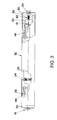
- Figs. 2 and 3 show the air dryer 16 in partial cut-away cross-section.
- the air dryer 16 includes a membrane module 24, inlet end cap 28 including inlet port 18, outlet end cap 30 including outlet port 20, and tubular shroud 32.
- the inlet end cap 28 and outlet end cap 30 are threadedly engaged with threads on respective ends of the membrane module 24.
- the tubular shroud 32 extends between the inlet and outlet end caps 28 and 30 and surrounds the membrane module 24.
- the tubular shroud 32 is captured between respective radially outwardly extending shoulders 34 and 36 on the inlet and outlet end caps 28 and 30.
- a watertight seal can be provided between the inlet end cap 28 and the tubular shroud 32. This can be accomplished with seal members such as o-rings, or by provided a raised bead 37 on the inlet end cap 28 that fits within the tubular shroud 32 immediately adjacent its end, for example as shown in Fig. 8 .
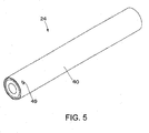
- the membrane module 24 generally includes a cylindrical membrane core 40 and a plurality of hollow fibres 42 supported therein.
- the hollow fibres 42 have passageways for the flow of the gas (e.g., air) to be dried. Interstitial spaces 44 between the plurality of hollow fibres 42 provide a flowpath for sweep gas to drive away moisture that permeates the hollow fibres 42.
- the hollow fibres 42 can be made from a variety of materials, including polymers such as, for example, polysulphone, poly(ether sulphone), polyimide, polyamide, poly(vinyl pyrrolidone), poly(phenylene oxide), poly(phenyl sulphone), and poly(vinylidene fluoride).
- the passageways in the hollow fibre 42 and the interstitial spaces 44 between the hollow fibres 42 are generally fluidicly isolated. In this sense, air flowing through the passageways of the fibres 42 enters the upstream end and exits the downstream end, while moisture in the air permeates the hollow fibres 42 to the interstitial spaces 44.
- the ends of the membrane module 24 are sealed such that air from the inlet 18 may generally only flow into the passageways in the hollow fibres 42 and not to the interstitial spaces 44 between the hollow fibres 42.
- the membrane core 40 has one or more sweep gas exhaust ports 49 for exhausting sweep gas from within the core 40 of the membrane module 24.
- the inlet and outlet end caps 28 and 30 are threaded on to the membrane module 24, with respective o-rings 46 and 48 forming a seal between them.
- this provides a generally isolated flow path for the compressed air from the inlet port 18, through the membrane module 24 via the passageways in the hollow fibres 42, to an outlet chamber 50 formed between the outlet end cap 30 and the membrane module 24, to the outlet port 20.
- a sweep gas orifice 51 is located within the outlet chamber 50 for routing a portion of the dried gas flowing therethrough to the sweep gas circuit.
- an orifice 52 is provided in the outlet end cap 30.
- the orifice 52 is threaded into a central bore 54 or aperture of the outlet end cap 30.
- the orifice 52 is provided as part of a set screw body that can be installed and readily removed from the outlet end cap 30, for example through the outlet port 20. This permits various size orifices to be installed to generate different flow rates and/or dewpoint suppression for different applications. Alternatively, several different outlet end caps could be provided with different orifice sizes, and the entire outlet end cap could be change out as desired. In some cases, it may be desirable to press fit the orifice 52 into the bore 54.
- the orifice 52 generally controls the flow from the outlet of the membrane module 24 through the central bore 54.
- Figs. 6 and 7 show the outlet end cap 30 with a generally cylindrical body 60 including the axially extending central bore 54.
- the opening of the bore 54 visible in Fig. 6 is adapted for receiving an outlet end of the membrane module 24.
- internal threads can be provided on the interior of the bore 54 adjacent such opening for threadedly engaging corresponding threads on the membrane module 24.
- the opposite opening of the bore 62 (not visible in Fig. 6 ) is adapted for receiving the outlet port 20.
- a pair of axially extending sweep gas exhaust channels 66 in the outer circumferential surface of the body 60 cooperate with the tubular shroud 32 to form sweep gas exhaust passageways for exhausting the sweep gas from the air dryer 10.
- Fig. 9 shows the air dryer 16 in an exploded state that shows the manner in which the various components are arranged when assembled.
- the inlet end cap 28 is connected to the membrane module 24, the tubular shroud 32 is then telescoped over the membrane module 24, and the outlet end cap 30 is then connected to the end of the membrane module 24 thereby trapping the tubular shroud between the shoulders 34 and 36 of the end caps.
- compressed air is fed to the inlet port 18 from a compressed air supply, such as a compressor or accumulator tank.
- a compressed air supply such as a compressor or accumulator tank.
- the compressed air then passes through the inlet end cap 28 and into the passageways of the hollow fibres 42.
- moisture in the air permeates the fibres 42 thereby drying the air.
- the dried air then exits the hollow fibres 42 into the chamber 50 formed by the outlet end cap 30 and the membrane module 24.
- a majority of the dried air then flows through the orifice 52 to the outlet port 20 for supply to an electrical cabinet or other device.
- a portion of the dried air is routed back to the interstitial spaces 44 between the hollow tubes via sweep orifice 51.
- This sweep gas serves to absorb the moisture that has permeated the hollow tubes 42 and to carry such moisture out of the membrane module 24 via cartridge exhaust ports 49 (see Fig. 5 ) in the membrane core 40.
- the sweep gas then flows in the annular space between the tubular shroud 32 and the membrane module 24, generally defining a longitudinally extending passageway, to the exhaust channels 66 of the outlet end cap 30.
- the sweep gas then exits the air dryer 16 through the passageways formed between the tubular shroud 32 and the channels 66 in the outlet end cap 30.
- the internal orifice 52 of the air dryer 16 provides a consistent and more stable outlet flow and dew point.
- the air dryer 16 is more user friendly and eliminates the uncertainty associated with having to measure and set the outlet flow and dew point. This feature is especially advantageous in applications, such as a food plant setting, that may lack the instruments to measure outlet flow and dew point.
- tubular shroud 32 of the air dryer 16 provides a more uniform surface that is free of catch points where food and/or other debris may catch and allow bacteria to grow.
- the tubular shroud also protects the membrane module 24 from harsh cleaning chemicals and provides a longitudinal passageway for the sweep gas enabling a bottom vent arrangement that is less prone to contamination or clogging from cleaning solutions and/or food particles.
Landscapes
- Chemical & Material Sciences (AREA)
- Chemical Kinetics & Catalysis (AREA)
- Engineering & Computer Science (AREA)
- Analytical Chemistry (AREA)
- General Chemical & Material Sciences (AREA)
- Oil, Petroleum & Natural Gas (AREA)
- Separation Using Semi-Permeable Membranes (AREA)
Abstract
Description
- The present invention relates generally to membrane gas dryers for drying a stream of gas and, more particularly, to membrane air dryers for drying compressed air.
- Electrical components in processing plants are commonly provided in enclosures. It can be desirable to clean equipment in processing plants to meet relevant regulations. This can be desirable in processing plants for preparing foodstuffs. It can also be desirable in other industries where cleanliness or sterility or both are important, for example in relation to medical products such as pharmaceuticals and medical implants, apparatus and instruments.
- For example, food processing plants typically must be cleaned at regular intervals in order to comply with various governmental regulations intended to ensure food safety. In many food processing plants, this entails shutting down at least a portion of the plant and manually cleaning the plant using various detergents. In many cases, the detergents are applied by cleaning personnel via a hose or the like. In other cases, a fixed cleaning system including an array of nozzles may automatically wash down the plant.
- In either case, during cleaning the potential exists for water and/or detergent solutions to enter electrical boxes within the plant associated with the processing equipment. Since electrical components typically do not fare well when exposed to moisture, it is common to provide such electrical boxes with gaskets and other sealing elements in an attempt to make them waterproof. Regardless of such efforts, however, the opportunity remains for moisture to enter the boxes.
- To address this issue, some processing plants supply a stream of dry compressed air to each electrical box. Since compressed air is generally moisture-laden, membrane air dryers have been employed to dry the air after it is compressed. The dry air is then circulated through the boxes to absorb and remove any moisture therein.
- Such dryers are known in the art of compressed gas systems and are devices that remove water from a compressed air system, specifically the water that exists in the vapour phase. The performance of such air driers, which typically contain a membrane module, is generally measured by the dewpoint suppression achieved as air passes through the module. The dewpoint is the temperature at which moisture will start to condense out of the moist air. Dewpoint suppression is the number of degrees the dew point is lowered as the air passes through the drier.
- The dewpoint suppression is a function of the membrane area, feed flow rate, operating pressure and temperature, and sweep fraction. Membrane air dryers typically function by contacting one side of a semi-permeable membrane with a pressurized wet feed stream. The membrane preferentially allows water vapour to permeate through it resulting in a drying of the compressed air stream. A portion of the dried gas, commonly referred to as the "sweep", is fed back to contact the other side of the membrane and acts to sweep away the water moisture that has permeated the membrane. The sweep is often controlled by an externally mounted valve or an internal orifice. Such dryers typically employ an external valve or pressure regulator for controlling the flow of compressed air through the dryer.
- An air dryer having an internal orifice designed into an outlet end cap that eliminates the need for external valves or regulators to control the flow of air through the dryer. The internal orifice, which can be press-fit or threaded into the end cap, provides a consistent and stable outlet flow and dew point. Preset outlet flow and dew point is more user friendly and eliminates the uncertainty associated with having to determine the outlet flow and dew point. This feature is especially advantageous in applications that lack the instruments to measure outlet flow and dew point, such as for example processing plants which are used to prepare foodstuffs. Another benefit is that the orifice size can be easily changed with a wrench thereby changing outlet flow and dew point, if so desired.
- In addition, since known air dryers are generally not suitable for use in air drying systems of processing plants where they can be exposed to harsh cleaning chemicals and/or can harbour contaminants (for example food particles in a food processing plant) that can encourage bacteria growth and unsanitary conditions, the air dryer includes a protective sleeve in the form of a tubular shroud. The tubular shroud shields the membrane module from exposure to cleaning chemicals and provides an exterior surface that is easy to clean and is generally free of cavities for contaminants to accumulate. The air dryer also includes an exhaust port for venting the sweep gas at a lower side thereof such that, when mounted, the sweep gas exhaust port can be shielded from infiltration by contaminant particles and/or cleaning chemicals.
- In one aspect, the invention provides a membrane air dryer which comprises a tubular hollow fibre membrane module, a tubular shroud enclosing the hollow fibre membrane module, and an outlet end cap including an outlet end cap body connected to an outlet end of the hollow fibre membrane module, the outlet end cap body having a central aperture fluidly connected with an outlet end of the membrane module, and at least one flow path externally spaced from the aperture and fluidly connected with an external sweep air region formed between the tubular membrane module and the tubular shroud.
- The at least one flow path can be formed by a channel along the exterior surface of the outlet end cap body, and the flow path is defined between the outlet end cap body and shroud. The outlet end cap can include an orifice for regulating flow through the aperture from the outlet end of the hollow fibre membrane module. The outlet end cap can further include an orifice body fixed within the central aperture of the end cap body, and defining the orifice. The orifice body can be press-fit or threadably received within the central aperture. The outlet end cap can be removably connected to the membrane module.
- The membrane air dryer can also include an inlet end cap including an inlet end cap body connected to an inlet end of the hollow fibre membrane module. A watertight seal can be provided between the inlet end cap and the tubular shroud. The tubular shroud can be captured between the inlet end cap and the outlet end cap.
- In another aspect, the invention provides a membrane air dryer which comprises a tubular hollow fibre membrane module having an inlet, an outlet and a bundle of hollow fibres supported therein, at least one of the hollow fibres having an interior passageway for the flow of air through the module from an upstream end near the inlet to a downstream end near the outlet, the hollow fibres having interstitial spaces therebetween for the flow of a sweep gas, and an outlet end cap. The outlet end cap includes an end cap body connected to the outlet end of the membrane module, the end cap body having a central aperture fluidly connected with the outlet of the membrane module and having an orifice for regulating flow through the aperture from the outlet end of the membrane module.
- The orifice can be included in an orifice body fixed within the central aperture of the end cap body. The orifice body can be press-fit or threadedly received within the central aperture. The outlet end cap can be removably connected to the membrane module.
- The membrane air dryer can further include a passageway for supplying a sweep gas to interstitial spaces between the hollow fibres, the passageway fluidly connecting the outlet of the membrane module to the interstitial spaces such that a portion of the air flowing through the hollow fibres can be utilized as sweep gas to remove moisture from the interstitial spaces. A sweep gas inlet orifice can be provided for controlling the flow of sweep gas through the passageway to the interstitial spaces.
- An inlet end cap can also be provided including an end cap body attached to the inlet end of the membrane module, the inlet end cap and outlet end cap being secured to respective ends of the membrane module and in fluid communication with the interior passageways of the hollow fibres. A tubular shroud can surround the membrane module and extend between the inlet and outlet end caps, the tubular shroud and membrane module defining a longitudinally extending passageway for the flow of sweep gas. The membrane module can have at least one exhaust port for exhausting sweep gas from the within the membrane module into the longitudinally extending passageway, and the outlet end cap can have at least one exhaust channel through which the sweep gas can vent from the longitudinally extending passageway. The at least one exhaust channel can extend axially on an outer circumference of the outlet end cap body, the tubular shroud and outlet end cap being axially coextensive along a portion of the exhaust channel.
- In a further aspect, the invention provides a method of assembling a membrane air dryer, which comprises the steps of connecting a first end cap to a first end of a tubular hollow membrane module, telescoping a tubular shroud over the membrane module, and attaching a second end cap to a second end of the tubular hollow membrane module while capturing the tubular shroud between the first and second end caps.
- Embodiments of the invention are described below by way of example with reference to the accompanying drawings, in which:
-
Fig. 1 is a schematic diagram of an air dryer system which includes an air dryer. -
Fig. 2 is a partially cut-away view of an air dryer. -
Fig. 3 is another partially cut-away view of the air dryer ofFig. 2 . -
Fig. 4 is a cross-sectional view of the air dryer ofFigs. 2 and3 with some components removed for clarity. -
Fig. 5 is a perspective view of a membrane module. -
Fig. 6 is a perspective view of an outlet end cap. -
Fig. 7 is an end view of the outlet end cap ofFig. 5 . -
Fig. 8 is a side elevational view of an inlet end cap. -
Fig. 9 is an exploded view of the exemplary air dryer ofFigs. 2 to 4 . - Referring to the drawings,
Fig. 1 shows anair drying system 10 for drying anelectrical cabinet 12, which includes acompressed air supply 14, anair dryer 16, andelectrical cabinet 12. Compressed air is delivered to aninlet 18 of theair dryer 16 from thesupply 14. The air is dried as it passes through theair dryer 16 tooutlet 20. The dry air is then fed to theelectrical cabinet 12 where it absorbs and removes any moisture from within the cabinet. Theair dryer 16 includes a sweepgas exhaust port 22 on its bottom side near theoutlet 20 for exhausting the sweep gas from theair dryer 16. Although theair dryer 16 is shown and described in the context of a food processing plant air drying system, it will be appreciated that theair dryer 16 can be used in a wide variety of applications and can dry gasses other than air. -
Figs. 2 and3 show theair dryer 16 in partial cut-away cross-section. Theair dryer 16 includes amembrane module 24,inlet end cap 28 includinginlet port 18,outlet end cap 30 includingoutlet port 20, andtubular shroud 32. As best seen inFig. 3 , theinlet end cap 28 andoutlet end cap 30 are threadedly engaged with threads on respective ends of themembrane module 24. Thetubular shroud 32 extends between the inlet and outlet end caps 28 and 30 and surrounds themembrane module 24. In the embodiment shown in the drawings, thetubular shroud 32 is captured between respective radially outwardly extendingshoulders inlet end cap 28 and thetubular shroud 32. This can be accomplished with seal members such as o-rings, or by provided a raisedbead 37 on theinlet end cap 28 that fits within thetubular shroud 32 immediately adjacent its end, for example as shown inFig. 8 . - With additional reference to
Figs. 4 and5 , themembrane module 24 generally includes acylindrical membrane core 40 and a plurality ofhollow fibres 42 supported therein. Thehollow fibres 42 have passageways for the flow of the gas (e.g., air) to be dried. Interstitial spaces 44 between the plurality ofhollow fibres 42 provide a flowpath for sweep gas to drive away moisture that permeates thehollow fibres 42. As will be appreciated, thehollow fibres 42 can be made from a variety of materials, including polymers such as, for example, polysulphone, poly(ether sulphone), polyimide, polyamide, poly(vinyl pyrrolidone), poly(phenylene oxide), poly(phenyl sulphone), and poly(vinylidene fluoride). - The passageways in the
hollow fibre 42 and the interstitial spaces 44 between thehollow fibres 42 are generally fluidicly isolated. In this sense, air flowing through the passageways of thefibres 42 enters the upstream end and exits the downstream end, while moisture in the air permeates thehollow fibres 42 to the interstitial spaces 44. The ends of themembrane module 24 are sealed such that air from theinlet 18 may generally only flow into the passageways in thehollow fibres 42 and not to the interstitial spaces 44 between thehollow fibres 42. As will be described in more detail below, themembrane core 40 has one or more sweepgas exhaust ports 49 for exhausting sweep gas from within thecore 40 of themembrane module 24. - Returning to
Fig. 3 , it will be appreciated that the inlet and outlet end caps 28 and 30 are threaded on to themembrane module 24, with respective o-rings inlet port 18, through themembrane module 24 via the passageways in thehollow fibres 42, to anoutlet chamber 50 formed between theoutlet end cap 30 and themembrane module 24, to theoutlet port 20. In order to provide sweep gas to the interstitial spaces between thehollow fibres 42, asweep gas orifice 51 is located within theoutlet chamber 50 for routing a portion of the dried gas flowing therethrough to the sweep gas circuit. - To regulate the flow of air through the
dryer 16, anorifice 52 is provided in theoutlet end cap 30. In the illustrated embodiment, theorifice 52 is threaded into acentral bore 54 or aperture of theoutlet end cap 30. Thus, theorifice 52 is provided as part of a set screw body that can be installed and readily removed from theoutlet end cap 30, for example through theoutlet port 20. This permits various size orifices to be installed to generate different flow rates and/or dewpoint suppression for different applications. Alternatively, several different outlet end caps could be provided with different orifice sizes, and the entire outlet end cap could be change out as desired. In some cases, it may be desirable to press fit theorifice 52 into thebore 54. Theorifice 52 generally controls the flow from the outlet of themembrane module 24 through thecentral bore 54. -
Figs. 6 and7 show theoutlet end cap 30 with a generallycylindrical body 60 including the axially extendingcentral bore 54. The opening of thebore 54 visible inFig. 6 is adapted for receiving an outlet end of themembrane module 24. As such, internal threads can be provided on the interior of thebore 54 adjacent such opening for threadedly engaging corresponding threads on themembrane module 24. The opposite opening of the bore 62 (not visible inFig. 6 ) is adapted for receiving theoutlet port 20. A pair of axially extending sweepgas exhaust channels 66 in the outer circumferential surface of thebody 60 cooperate with thetubular shroud 32 to form sweep gas exhaust passageways for exhausting the sweep gas from theair dryer 10. -
Fig. 9 shows theair dryer 16 in an exploded state that shows the manner in which the various components are arranged when assembled. As will be appreciated, during assembly theinlet end cap 28 is connected to themembrane module 24, thetubular shroud 32 is then telescoped over themembrane module 24, and theoutlet end cap 30 is then connected to the end of themembrane module 24 thereby trapping the tubular shroud between theshoulders - Referring back to
Figs. 2 and3 , in operation compressed air is fed to theinlet port 18 from a compressed air supply, such as a compressor or accumulator tank. The compressed air then passes through theinlet end cap 28 and into the passageways of thehollow fibres 42. As the air passes through thehollow fibres 42, moisture in the air permeates thefibres 42 thereby drying the air. The dried air then exits thehollow fibres 42 into thechamber 50 formed by theoutlet end cap 30 and themembrane module 24. A majority of the dried air then flows through theorifice 52 to theoutlet port 20 for supply to an electrical cabinet or other device. A portion of the dried air is routed back to the interstitial spaces 44 between the hollow tubes viasweep orifice 51. This sweep gas serves to absorb the moisture that has permeated thehollow tubes 42 and to carry such moisture out of themembrane module 24 via cartridge exhaust ports 49 (seeFig. 5 ) in themembrane core 40. The sweep gas then flows in the annular space between thetubular shroud 32 and themembrane module 24, generally defining a longitudinally extending passageway, to theexhaust channels 66 of theoutlet end cap 30. The sweep gas then exits theair dryer 16 through the passageways formed between thetubular shroud 32 and thechannels 66 in theoutlet end cap 30. - The
internal orifice 52 of theair dryer 16 provides a consistent and more stable outlet flow and dew point. By using theinternal orifice 52 to preset the outlet flow and dew point, theair dryer 16 is more user friendly and eliminates the uncertainty associated with having to measure and set the outlet flow and dew point. This feature is especially advantageous in applications, such as a food plant setting, that may lack the instruments to measure outlet flow and dew point. - Further, the
tubular shroud 32 of theair dryer 16 provides a more uniform surface that is free of catch points where food and/or other debris may catch and allow bacteria to grow. The tubular shroud also protects themembrane module 24 from harsh cleaning chemicals and provides a longitudinal passageway for the sweep gas enabling a bottom vent arrangement that is less prone to contamination or clogging from cleaning solutions and/or food particles. - In relation to the various functions performed by the above described elements (components, assemblies, devices, compositions, etc.), the terms (including a reference to a "means") used to describe such elements are intended to correspond, unless otherwise indicated, to any element which performs the specified function of the described element (i.e., that is functionally equivalent), even though not structurally equivalent to the disclosed structure which performs the function in the described embodiment or embodiments of the invention. In addition, while a particular feature of the invention may have been described above with respect to only one or more of several embodiments, such feature may be combined with one or more other features of the other embodiments, as may be desired and advantageous for any given or particular application.
Claims (15)
- A membrane air dryer (16), comprising:a tubular hollow fibre membrane module (24);a tubular shroud (32) enclosing the hollow fibre membrane module (24); andan outlet end cap (30) including an outlet end cap body (60) connected to an outlet end of the hollow fibre membrane module (24), the outlet end cap body (60) having a central aperture (54) fluidly connected with an outlet of the membrane module (24), and at least one flow path externally spaced from the aperture (54) and fluidly connected with an external sweep air region formed between the tubular membrane module (24) and the tubular shroud (32).
- A membrane air dryer (16) as set forth in claim 1, wherein the at least one flow path is formed by a channel (66) along the exterior surface of the outlet end cap body (60), and the flow path is defined between the outlet end cap body (60) and tubular shroud (32).
- A membrane air dryer (16) as set forth in any one of claims 1 and 2, wherein the outlet end cap (30) includes an orifice (52) for regulating flow through the aperture from the outlet end of the hollow fibre membrane module (24).
- A membrane air dryer (16) as set forth in claim 3, wherein the outlet end cap (30) further includes an orifice body fixed within the central aperture of the end cap body, and defining the orifice (52).
- A membrane air dryer (16) as set forth in claim 4, wherein the orifice body is press-fit or threadably received within the central aperture.
- A membrane air dryer (16) as set forth in any one of claims 1 to 5, wherein the outlet end cap (30) is removably connected to the membrane module (24).
- A membrane air dryer (16) as set forth in any one of claims 1 to 6, further comprising an inlet end cap (28) including an inlet end cap body connected to an inlet end of the hollow fibre membrane module (24), wherein a watertight seal is preferably provided between the inlet end cap (28) and the tubular shroud (32).
- A membrane air dryer (16) as set forth in any one of claims 1 to 7, wherein the tubular shroud (32) is captured between an inlet end cap (28) including an inlet end cap body connected to an inlet end of the hollow fibre membrane module (24) end cap, and the outlet end cap (30).
- A membrane air dryer (16) comprising:a tubular hollow fibre membrane module (24) having an inlet, an outlet and a bundle of hollow fibres (42) supported therein, at least one of the hollow fibres having an interior passageway for the flow of air through the module (24) from an upstream end near the inlet to a downstream end near the outlet, the hollow fibres having interstitial spaces (44) therebetween for the flow of a sweep gas; andan outlet end cap (30) including an outlet end cap body (60) connected to the outlet end of the membrane module (24), the outlet end cap body (60) having a central aperture fluidly connected with the outlet of the membrane module (24) and having an orifice (52) for regulating flow through the aperture from the outlet end of the membrane module (24).
- A membrane air dryer (16) as set forth in claim 9, wherein the orifice (52) is included in an orifice body fixed within the central aperture of the outlet end cap body (60) and wherein the orifice body is preferably press-fit or threadably received within the central aperture.
- A membrane air dryer (16) as set forth in any one of claims 9 and 10, wherein the outlet end cap (30) is removably connected to the membrane module (24).
- A membrane air dryer (16) as set forth in any one of claims 9 to 11, further comprising an inlet end cap (28) including an end cap body attached to the inlet of the membrane module (24), the inlet end cap (28) and outlet end cap (30) being secured to respective ends of the membrane module (24) and in fluid communication with the interior passageways of the hollow fibres (42), and a tubular shroud (32) surrounding the membrane module (24) and extending between the inlet and outlet end caps, the tubular shroud (32) and membrane module (24) defining a longitudinally extending passageway for the flow of sweep gas.
- A membrane air dryer (16) as set forth in any one of claims 9 to 12, wherein the membrane module (24) has at least one exhaust port for exhausting sweep gas from within the membrane module (24) into the longitudinally extending passageway, and wherein the outlet end cap (30) has at least one exhaust channel (66) through which the sweep gas can vent from the longitudinally extending passageway.
- A membrane air dryer (16) as set forth in claim 13, wherein the at least one exhaust channel (66) extends axially on an outer circumference of the outlet end cap body (60), the tubular shroud (32) and outlet end cap (30) being axially coextensive along a portion of the exhaust channel (66).
- A method of rejuvenating a membrane air dryer (16) according to any one of the preceding claims, comprising the steps of:removing a first end cap from the air dryer (16);removing a tubular shroud (32) covering a membrane module (24);replacing the membrane module (24) by removing it from a second end cap;reinstalling the tubular shroud (32) by telescoping the shroud (32) over the membrane module (24); andreinstalling the first end cap while capturing the tubular shroud (32) between the first and second end caps.
Applications Claiming Priority (1)
| Application Number | Priority Date | Filing Date | Title |
|---|---|---|---|
| US15399309P | 2009-02-20 | 2009-02-20 |
Publications (2)
| Publication Number | Publication Date |
|---|---|
| EP2226112A2 true EP2226112A2 (en) | 2010-09-08 |
| EP2226112A3 EP2226112A3 (en) | 2010-10-20 |
Family
ID=42125923
Family Applications (1)
| Application Number | Title | Priority Date | Filing Date |
|---|---|---|---|
| EP10154076A Withdrawn EP2226112A3 (en) | 2009-02-20 | 2010-02-19 | Air Dryer for Electrical Enclosures |
Country Status (2)
| Country | Link |
|---|---|
| US (1) | US8328912B2 (en) |
| EP (1) | EP2226112A3 (en) |
Cited By (1)
| Publication number | Priority date | Publication date | Assignee | Title |
|---|---|---|---|---|
| US8328912B2 (en) | 2009-02-20 | 2012-12-11 | Parker-Hannifin Corporation | Air dryer for electrical enclosures |
Families Citing this family (2)
| Publication number | Priority date | Publication date | Assignee | Title |
|---|---|---|---|---|
| US9186629B2 (en) * | 2013-08-26 | 2015-11-17 | Cameron Solutions, Inc. | Single end, shell-side feed, hollow fiber membrane separation module |
| US11446610B2 (en) * | 2019-04-03 | 2022-09-20 | Generon Igs, Inc. | Gas separation membrane module with enhanced performance |
Family Cites Families (17)
| Publication number | Priority date | Publication date | Assignee | Title |
|---|---|---|---|---|
| US3339351A (en) * | 1965-03-12 | 1967-09-05 | Otto H York Company Inc | Apparatus for removing liquid particles in a gas stream |
| US4666469A (en) * | 1985-05-29 | 1987-05-19 | The Dow Chemical Company | Hollow fiber membrane device with inner wrap |
| US5622857A (en) * | 1995-08-08 | 1997-04-22 | Genespan Corporation | High performance cell culture bioreactor and method |
| US5411662A (en) * | 1994-02-25 | 1995-05-02 | Praxair Technology, Inc. | Fluid separation assembly having an purge control valve |
| US5525143A (en) * | 1994-10-17 | 1996-06-11 | Air Products And Chemicals, Inc. | Hollow fiber membrane dryer with internal sweep |
| US5605564A (en) * | 1996-02-14 | 1997-02-25 | Howell Laboratories, Inc. | Membrane gas dehydrator |
| AU1364501A (en) * | 1999-11-12 | 2001-06-06 | Porous Media Corporation | Compressed gas systems utilizing a variable pressure membrane air drier, and method of operation thereof |
| JP2001239125A (en) * | 2000-03-01 | 2001-09-04 | Nabco Ltd | Hollow-fiber membrane dehumidifier |
| US6585808B2 (en) * | 2000-12-08 | 2003-07-01 | Porous Media Corporation | Membrane air dryer with integral diffuser and method of manufacture thereof |
| US6814780B2 (en) * | 2001-05-02 | 2004-11-09 | L'air Liquide, Societe Anonyme A Directoire Et Conseil De Surveillance Pour L'etude Et L'exploitation Des Procedes Georges Claude | Hollow fiber membrane gas separation cartridge and gas purification assembly |
| US6755894B2 (en) * | 2001-05-02 | 2004-06-29 | Praxair Technology, Inc. | Hollow fiber membrane gas separation cartridge and gas purification assembly |
| US6740140B2 (en) * | 2001-09-07 | 2004-05-25 | Praxair Technology, Inc. | Hollow fiber membrane system assembly with an internal reflux system |
| US6764529B2 (en) * | 2002-07-01 | 2004-07-20 | Bendix Commercial Vehicle Systems Llc | Membrane gas dehydrating apparatus for gas controlled and powered systems |
| US6923845B2 (en) * | 2002-10-18 | 2005-08-02 | Bendix Commercial Vehicle Systems Llc | Membrane air dryer for vehicle air brake system |
| US7169213B2 (en) * | 2004-10-29 | 2007-01-30 | Corning Incorporated | Multi-channel cross-flow porous device |
| US7678177B2 (en) * | 2006-09-12 | 2010-03-16 | New York Air Brake Corporation | Membrane air dryer and sweep valve |
| US8328912B2 (en) | 2009-02-20 | 2012-12-11 | Parker-Hannifin Corporation | Air dryer for electrical enclosures |
-
2010
- 2010-02-19 US US12/708,605 patent/US8328912B2/en active Active
- 2010-02-19 EP EP10154076A patent/EP2226112A3/en not_active Withdrawn
Non-Patent Citations (1)
| Title |
|---|
| None |
Cited By (1)
| Publication number | Priority date | Publication date | Assignee | Title |
|---|---|---|---|---|
| US8328912B2 (en) | 2009-02-20 | 2012-12-11 | Parker-Hannifin Corporation | Air dryer for electrical enclosures |
Also Published As
| Publication number | Publication date |
|---|---|
| US8328912B2 (en) | 2012-12-11 |
| US20100212502A1 (en) | 2010-08-26 |
| EP2226112A3 (en) | 2010-10-20 |
Similar Documents
| Publication | Publication Date | Title |
|---|---|---|
| EP1473073B1 (en) | Membrane filter with deaeration and method for the manufacture thereof | |
| CN109922874B (en) | Dehumidifying element and dehumidifying device with the same | |
| KR100296232B1 (en) | Low hold-up volume filter assembly | |
| CN102812545B (en) | Porous Baffles for Uniform Distribution of Purge Gas in Microenvironments | |
| KR102177864B1 (en) | Isolation valve | |
| US20170240440A1 (en) | Filter | |
| US8328912B2 (en) | Air dryer for electrical enclosures | |
| KR101365067B1 (en) | Integral sweep controller for gas membrane separation device | |
| KR100907551B1 (en) | Integrated Air Dryer System | |
| MX2011003944A (en) | Membrane air dryer. | |
| US20230120721A1 (en) | Fluid purification systems and methods | |
| RU2668908C1 (en) | Unit for the nitrogen from air separation using the hollow fiber membranes | |
| JP5424233B2 (en) | Compressed air dehumidification system | |
| US20250153082A1 (en) | Air filter for compressed air | |
| US20100258654A1 (en) | Quick disconnect spray nozzle with transversely oriented discharge orifices | |
| KR100705546B1 (en) | Immersion hollow fiber membrane module | |
| US20060108276A1 (en) | Cartridge filter system with lift tube | |
| CN108894961A (en) | A kind of gas pretreatment device used for air compressor | |
| CN208115459U (en) | dry gas filter | |
| WO2012072452A2 (en) | Water filter apparatus | |
| WO2003046520A1 (en) | Method and apparatus for monitoring building air flow | |
| KR200457493Y1 (en) | Membrane dryer for air compressor | |
| JPH10235135A (en) | Gas dehumidifier | |
| US8323386B2 (en) | Apparatus and method for electrostatic particulate collector | |
| JP2007222716A (en) | Filter cleaning container |
Legal Events
| Date | Code | Title | Description |
|---|---|---|---|
| PUAI | Public reference made under article 153(3) epc to a published international application that has entered the european phase |
Free format text: ORIGINAL CODE: 0009012 |
|
| AK | Designated contracting states |
Kind code of ref document: A2 Designated state(s): AT BE BG CH CY CZ DE DK EE ES FI FR GB GR HR HU IE IS IT LI LT LU LV MC MK MT NL NO PL PT RO SE SI SK SM TR |
|
| PUAL | Search report despatched |
Free format text: ORIGINAL CODE: 0009013 |
|
| AK | Designated contracting states |
Kind code of ref document: A3 Designated state(s): AT BE BG CH CY CZ DE DK EE ES FI FR GB GR HR HU IE IS IT LI LT LU LV MC MK MT NL NO PL PT RO SE SI SK SM TR |
|
| 17P | Request for examination filed |
Effective date: 20110420 |
|
| 17Q | First examination report despatched |
Effective date: 20130910 |
|
| GRAJ | Information related to disapproval of communication of intention to grant by the applicant or resumption of examination proceedings by the epo deleted |
Free format text: ORIGINAL CODE: EPIDOSDIGR1 |
|
| GRAP | Despatch of communication of intention to grant a patent |
Free format text: ORIGINAL CODE: EPIDOSNIGR1 |
|
| INTG | Intention to grant announced |
Effective date: 20150123 |
|
| GRAP | Despatch of communication of intention to grant a patent |
Free format text: ORIGINAL CODE: EPIDOSNIGR1 |
|
| INTG | Intention to grant announced |
Effective date: 20150318 |
|
| STAA | Information on the status of an ep patent application or granted ep patent |
Free format text: STATUS: THE APPLICATION IS DEEMED TO BE WITHDRAWN |
|
| 18D | Application deemed to be withdrawn |
Effective date: 20150729 |