EP2226011A1 - Transmit/Receive isolation for an ultrasound system - Google Patents
Transmit/Receive isolation for an ultrasound system Download PDFInfo
- Publication number
- EP2226011A1 EP2226011A1 EP10151379A EP10151379A EP2226011A1 EP 2226011 A1 EP2226011 A1 EP 2226011A1 EP 10151379 A EP10151379 A EP 10151379A EP 10151379 A EP10151379 A EP 10151379A EP 2226011 A1 EP2226011 A1 EP 2226011A1
- Authority
- EP
- European Patent Office
- Prior art keywords
- ultrasound
- transmit
- signals
- unit
- receiving unit
- Prior art date
- Legal status (The legal status is an assumption and is not a legal conclusion. Google has not performed a legal analysis and makes no representation as to the accuracy of the status listed.)
- Granted
Links
Images

Classifications
-
- A—HUMAN NECESSITIES
- A61—MEDICAL OR VETERINARY SCIENCE; HYGIENE
- A61B—DIAGNOSIS; SURGERY; IDENTIFICATION
- A61B8/00—Diagnosis using ultrasonic, sonic or infrasonic waves
- A61B8/13—Tomography
- A61B8/14—Echo-tomography
-
- A—HUMAN NECESSITIES
- A61—MEDICAL OR VETERINARY SCIENCE; HYGIENE
- A61B—DIAGNOSIS; SURGERY; IDENTIFICATION
- A61B8/00—Diagnosis using ultrasonic, sonic or infrasonic waves
-
- A—HUMAN NECESSITIES
- A61—MEDICAL OR VETERINARY SCIENCE; HYGIENE
- A61B—DIAGNOSIS; SURGERY; IDENTIFICATION
- A61B8/00—Diagnosis using ultrasonic, sonic or infrasonic waves
- A61B8/54—Control of the diagnostic device
-
- A—HUMAN NECESSITIES
- A61—MEDICAL OR VETERINARY SCIENCE; HYGIENE
- A61B—DIAGNOSIS; SURGERY; IDENTIFICATION
- A61B8/00—Diagnosis using ultrasonic, sonic or infrasonic waves
- A61B8/44—Constructional features of the ultrasonic, sonic or infrasonic diagnostic device
- A61B8/4444—Constructional features of the ultrasonic, sonic or infrasonic diagnostic device related to the probe
-
- A—HUMAN NECESSITIES
- A61—MEDICAL OR VETERINARY SCIENCE; HYGIENE
- A61B—DIAGNOSIS; SURGERY; IDENTIFICATION
- A61B8/00—Diagnosis using ultrasonic, sonic or infrasonic waves
- A61B8/44—Constructional features of the ultrasonic, sonic or infrasonic diagnostic device
- A61B8/4483—Constructional features of the ultrasonic, sonic or infrasonic diagnostic device characterised by features of the ultrasound transducer
-
- A—HUMAN NECESSITIES
- A61—MEDICAL OR VETERINARY SCIENCE; HYGIENE
- A61B—DIAGNOSIS; SURGERY; IDENTIFICATION
- A61B8/00—Diagnosis using ultrasonic, sonic or infrasonic waves
- A61B8/46—Ultrasonic, sonic or infrasonic diagnostic devices with special arrangements for interfacing with the operator or the patient
- A61B8/461—Displaying means of special interest
-
- A—HUMAN NECESSITIES
- A61—MEDICAL OR VETERINARY SCIENCE; HYGIENE
- A61B—DIAGNOSIS; SURGERY; IDENTIFICATION
- A61B8/00—Diagnosis using ultrasonic, sonic or infrasonic waves
- A61B8/48—Diagnostic techniques
- A61B8/485—Diagnostic techniques involving measuring strain or elastic properties
-
- A—HUMAN NECESSITIES
- A61—MEDICAL OR VETERINARY SCIENCE; HYGIENE
- A61B—DIAGNOSIS; SURGERY; IDENTIFICATION
- A61B8/00—Diagnosis using ultrasonic, sonic or infrasonic waves
- A61B8/48—Diagnostic techniques
- A61B8/488—Diagnostic techniques involving Doppler signals
-
- A—HUMAN NECESSITIES
- A61—MEDICAL OR VETERINARY SCIENCE; HYGIENE
- A61B—DIAGNOSIS; SURGERY; IDENTIFICATION
- A61B8/00—Diagnosis using ultrasonic, sonic or infrasonic waves
- A61B8/52—Devices using data or image processing specially adapted for diagnosis using ultrasonic, sonic or infrasonic waves
- A61B8/5207—Devices using data or image processing specially adapted for diagnosis using ultrasonic, sonic or infrasonic waves involving processing of raw data to produce diagnostic data, e.g. for generating an image
-
- G—PHYSICS
- G01—MEASURING; TESTING
- G01N—INVESTIGATING OR ANALYSING MATERIALS BY DETERMINING THEIR CHEMICAL OR PHYSICAL PROPERTIES
- G01N29/00—Investigating or analysing materials by the use of ultrasonic, sonic or infrasonic waves; Visualisation of the interior of objects by transmitting ultrasonic or sonic waves through the object
- G01N29/22—Details, e.g. general constructional or apparatus details
- G01N29/24—Probes
-
- G—PHYSICS
- G01—MEASURING; TESTING
- G01S—RADIO DIRECTION-FINDING; RADIO NAVIGATION; DETERMINING DISTANCE OR VELOCITY BY USE OF RADIO WAVES; LOCATING OR PRESENCE-DETECTING BY USE OF THE REFLECTION OR RERADIATION OF RADIO WAVES; ANALOGOUS ARRANGEMENTS USING OTHER WAVES
- G01S5/00—Position-fixing by co-ordinating two or more direction or position line determinations; Position-fixing by co-ordinating two or more distance determinations
- G01S5/18—Position-fixing by co-ordinating two or more direction or position line determinations; Position-fixing by co-ordinating two or more distance determinations using ultrasonic, sonic or infrasonic waves
-
- G—PHYSICS
- G01—MEASURING; TESTING
- G01S—RADIO DIRECTION-FINDING; RADIO NAVIGATION; DETERMINING DISTANCE OR VELOCITY BY USE OF RADIO WAVES; LOCATING OR PRESENCE-DETECTING BY USE OF THE REFLECTION OR RERADIATION OF RADIO WAVES; ANALOGOUS ARRANGEMENTS USING OTHER WAVES
- G01S7/00—Details of systems according to groups G01S13/00, G01S15/00, G01S17/00
- G01S7/52—Details of systems according to groups G01S13/00, G01S15/00, G01S17/00 of systems according to group G01S15/00
- G01S7/52017—Details of systems according to groups G01S13/00, G01S15/00, G01S17/00 of systems according to group G01S15/00 particularly adapted to short-range imaging
-
- G—PHYSICS
- G01—MEASURING; TESTING
- G01S—RADIO DIRECTION-FINDING; RADIO NAVIGATION; DETERMINING DISTANCE OR VELOCITY BY USE OF RADIO WAVES; LOCATING OR PRESENCE-DETECTING BY USE OF THE REFLECTION OR RERADIATION OF RADIO WAVES; ANALOGOUS ARRANGEMENTS USING OTHER WAVES
- G01S7/00—Details of systems according to groups G01S13/00, G01S15/00, G01S17/00
- G01S7/52—Details of systems according to groups G01S13/00, G01S15/00, G01S17/00 of systems according to group G01S15/00
- G01S7/52017—Details of systems according to groups G01S13/00, G01S15/00, G01S17/00 of systems according to group G01S15/00 particularly adapted to short-range imaging
- G01S7/5205—Means for monitoring or calibrating
Definitions
- the present disclosure relates to ultrasound systems, and more particularly to transmit/receive isolation for an ultrasound system, with which a high voltage transmit signal is blocked from being propagated to a receiving unit during a transmission period.
- an ultrasound system Due to its non-invasive and non-destructive nature, an ultrasound system has been extensively used for acquiring internal information of a target object in the medical profession. Since the ultrasound system may provide a high resolution image to a doctor without a surgical treatment, which is performed by directly incising and observing the target object, it is very helpful in the medical profession.
- an ultrasound system includes a transmit/receive switch.
- the transmit/receive switch connects a transmitting unit with an ultrasound probe during a transmission period of an ultrasound signal to transmit a high voltage transmit signal from a receiving unit to an ultrasound probe.
- the transmit/receive switch blocks a transmit signal to be propagated to the receiving unit.
- the transmit/receive switch connects the receiving unit with the ultrasound probe during a receiving period of an ultrasound signal to transmit the receive signal outputted from the ultrasound probe, which receives the ultrasound signal reflected from a target object (i.e., ultrasound echo signal), to the receiving unit.
- a target object i.e., ultrasound echo signal
- Embodiments of an ultrasound system for blocking a high voltage transmit signal to be propagated to a receiving unit during a transmission period of an ultrasound signal are disclosed herein.
- an ultrasound system comprises: a transmitting unit configured to form a plurality of transmit signals; an ultrasound probe configured to convert the transmit signals to a plurality of ultrasound signals, transmit the ultrasound signals to a target object, receive a plurality of echo signals reflected from the target object and form a plurality of receive signals based on the echo signals; a receiving unit; and a switching unit coupled to the transmitting unit, the ultrasound probe and the receiving unit and comprising a plurality of diode bridges each being switchable between first and second states such that the respective transmit signal is blocked from being propagated to the receiving unit when the diode bridge is in the first state and the respective receive signal is allowed to be propagated to the receiving unit when the diode bridge is in the second state.
- an ultrasound system comprises: a transmitting unit configured to form a plurality of transmit signals; an ultrasound probe configured to convert the transmit signals to a plurality of ultrasound signals, transmit the ultrasound signals to a target object, receive a plurality of echo signals reflected from the target object and form a plurality of receive signals based on the echo signals; a receiving unit; a switching unit coupled to the transmitting unit, the ultrasound probe and the receiving unit; a voltage measuring unit configured to easure a voltage of each of the transmit signals to form a measured voltage; and a control unit configured to perform the following steps: comparing the measured voltage with a predetermined threshold voltage, controlling the switching unit to block the transmit signal from being propagated to the receiving unit if the measured voltage is over the predetermined threshold voltage and controlling the switching unit to allow the receive signal to be propagated to the receiving unit if the measured voltage is below the predetermined threshold voltage.
- an ultrasound system comprises: a transmitting unit configured to form a plurality of transmit signals; an ultrasound probe configured to convert the transmit signals to a plurality of ultrasound signals, transmit the ultrasound signals to a target object, receive a plurality of echo signals reflected from the target object and form a plurality of receive signals based on the echo signals; a receiving unit; a switching unit coupled to the transmitting unit, the ultrasound probe and the receiving unit; a voltage measuring unit configured to measure a voltage of each of the transmit signals to form a measured voltage; and a control unit responsive to a blocking instruction to control the switching unit to block the corresponding transmit signal from being propagated to the receiving unit and further responsive to a non-blocking instruction to control the switching unit to allow the corresponding receive signal to be propagated to the receiving unit.
- an ultrasound system comprises: a transmitting unit configured to form a transmit signal; an ultrasound probe configured to convert the transmit signal to an ultrasound signal, the ultrasound probe being further configured to transmit the ultrasound signal to a target object during a transmit period, receive an echo signal reflected from the target object during a receive period and form a receive signal based on the echo signal; a receiving unit; and a switching unit coupled to the transmitting unit, the ultrasound probe and the receiving unit and comprising a plurality of diode bridges, each being configured to block the respective transmit signal from being propagated to the receiving unit during the transmit period and allow the respective receive signal to be propagated to the receiving unit during the receive period.
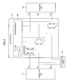
- FIG. 1 is a block diagram showing an illustrative embodiment of an ultrasound system applied to a switching unit 140 according to the present invention.
- a transmitting unit 110 forms a high voltage transmit signal to obtain frames.
- the frames include B mode (brightness mode) image, D mode (Doppler mode) image, c mode (color mode) image, elasticity image, etc.
- An ultrasound probe 120 converts transmit signals to a plurality of ultrasound signals, transmits them to a target object, receives a plurality of echo signals reflected from the target object and forms a plurality of receive signals based on the ultrasound echo signals.
- the ultrasound probe 120 includes a plurality of transducer elements for converting an ultrasound signal into an electronic signal and vice-versa.
- a receiving unit 130 converts a plurality of receive signals from the ultrasound probe 120 to analog signals.
- the receiving unit 130 focuses a plurality of receive signals, which are converted in digital, based on a focusing point and position of a transducer element on the ultrasound probe 120.
- the receiving unit 130 forms a plurality of ultrasound data by using the plurality of receive and focusing signals.
- a switching unit 140 is coupled to the transmitting unit 110, the ultrasound probe 120 and the receiving unit 130.
- the switching unit 140 connects the transmitting unit 110 to the ultrasound probe 120 during a transmission period of an ultrasound signal and transmits a high voltage transmit signal from the receiving unit 110 to the ultrasound probe 120.
- the switching unit 140 blocks the transmit signal to be propagated to the receiving unit 130.
- the switch unit 140 connects the receiving unit 130 with the ultrasound probe 120 during a receiving period of an ultrasound signal and transmits the receive signal from the ultrasound probe 120 to the receiving unit 130.
- the switching unit 140 is described for isolating the receiving unit 130 from transmit signal during the transmission period of the ultrasound signal.
- the switching unit 140 comprises a plurality of diode bridges, each being switchable between first and second states such that the respective transmit signal is blocked from being propagated to the receiving unit 130 when the diode bridge is in the first state and the respective receive signal is allowed to be propagated to the receiving unit 130 when the diode bridge is in the second state.
- the switching unit 140 further comprises a switching module 240 connected to the diode bridges. The switching module 240 is operable to reverse-bias the diode bridge in the first state and forward-bias the diode bridge in the second state.
- the switching module 240 comprises a pair of switches.
- a first switch SW 1 is connected to a minus voltage terminal -V and a second switch SW 2 is connected to a plus voltage terminal +V, to make the diode bridge off.
- a high voltage signal from the transmitting unit 110 may not be propagated to the receiving unit 130 and the receiving unit 130 can be completely isolated.
- the first switch SW 1 is connected to the plus voltage terminal +V and the second switch SW 2 is connected to a minus voltage terminal-V
- the diode bridge is on and forward bias current may be propagated to the diode bridge.
- the receive signal from the ultrasound probe 120 is transmitted to the receiving unit 130 via the diode bridge.
- the first and second switches can be implemented with mechanical relay transistors, field effect transistors (FET), etc.
- the switching module 240 is configured to control the diode bridges to be individually or simultaneously switchable.
- the control unit 150 controls the switching unit 140. Also, the control unit 150 controls transmit/receive of an ultrasound signal, as well as the formation and display of ultrasound images.
- the control unit 150 is responsive to a blocking instruction to control the switching unit to block the corresponding transmit signal from being propagated to the receiving unit, the control unit is further responsive to a non-blocking instruction to control the switching unit to allow the corresponding receive signal to be propagated to the receiving unit.
- a processor 160 forms ultrasound images by using a plurality of ultrasound data from the receiving unit 130.
- a display unit 170 displays ultrasound images formed in the processor 160.
- an ultrasound system may include a voltage measuring unit.
- the voltage measuring unit may measure voltage of each of transmit signals during a transmission period of ultrasound signals and form a measured voltage.
- the control unit 150 may be operable to perform the following steps: comparing the measured voltage with a predetermined threshold voltage, controlling the switching unit 140 to block the respective transmit signal from being propagated to the receiving unit 130 if the measured voltage is over the predetermined threshold voltage, controlling the switching unit 140 to allow the respective receive signal to be propagated to the receiving unit 130 if the measured voltage is below the threshold voltage.
Landscapes
- Health & Medical Sciences (AREA)
- Life Sciences & Earth Sciences (AREA)
- Engineering & Computer Science (AREA)
- Physics & Mathematics (AREA)
- General Health & Medical Sciences (AREA)
- Pathology (AREA)
- Medical Informatics (AREA)
- Animal Behavior & Ethology (AREA)
- Biophysics (AREA)
- Nuclear Medicine, Radiotherapy & Molecular Imaging (AREA)
- Veterinary Medicine (AREA)
- Radiology & Medical Imaging (AREA)
- Biomedical Technology (AREA)
- Heart & Thoracic Surgery (AREA)
- Public Health (AREA)
- Molecular Biology (AREA)
- Surgery (AREA)
- General Physics & Mathematics (AREA)
- Remote Sensing (AREA)
- Radar, Positioning & Navigation (AREA)
- Computer Networks & Wireless Communication (AREA)
- Computer Vision & Pattern Recognition (AREA)
- Gynecology & Obstetrics (AREA)
- Chemical & Material Sciences (AREA)
- Analytical Chemistry (AREA)
- Biochemistry (AREA)
- Immunology (AREA)
- Ultra Sonic Daignosis Equipment (AREA)
Abstract
Description
- The present application claims priority from Korean Patent Application No.
10-2009-18940 filed on March 5, 2009 - The present disclosure relates to ultrasound systems, and more particularly to transmit/receive isolation for an ultrasound system, with which a high voltage transmit signal is blocked from being propagated to a receiving unit during a transmission period.
- Due to its non-invasive and non-destructive nature, an ultrasound system has been extensively used for acquiring internal information of a target object in the medical profession. Since the ultrasound system may provide a high resolution image to a doctor without a surgical treatment, which is performed by directly incising and observing the target object, it is very helpful in the medical profession.
- Generally, an ultrasound system includes a transmit/receive switch. The transmit/receive switch connects a transmitting unit with an ultrasound probe during a transmission period of an ultrasound signal to transmit a high voltage transmit signal from a receiving unit to an ultrasound probe. At the same time, the transmit/receive switch blocks a transmit signal to be propagated to the receiving unit. The transmit/receive switch connects the receiving unit with the ultrasound probe during a receiving period of an ultrasound signal to transmit the receive signal outputted from the ultrasound probe, which receives the ultrasound signal reflected from a target object (i.e., ultrasound echo signal), to the receiving unit.
- When an ultrasound image in thin depth is obtained with the conventional ultrasound system, a high voltage transmit signal is propagated to the receiving unit. This is because the transmit/receive switch cannot completely block the transmit signal to be propagated to the receiving unit. This not only affects the receiving unit but also reduces quality of the ultrasound image.
- Embodiments of an ultrasound system for blocking a high voltage transmit signal to be propagated to a receiving unit during a transmission period of an ultrasound signal are disclosed herein.
- In one embodiment, by way of non-limiting example, an ultrasound system comprises: a transmitting unit configured to form a plurality of transmit signals; an ultrasound probe configured to convert the transmit signals to a plurality of ultrasound signals, transmit the ultrasound signals to a target object, receive a plurality of echo signals reflected from the target object and form a plurality of receive signals based on the echo signals; a receiving unit; and a switching unit coupled to the transmitting unit, the ultrasound probe and the receiving unit and comprising a plurality of diode bridges each being switchable between first and second states such that the respective transmit signal is blocked from being propagated to the receiving unit when the diode bridge is in the first state and the respective receive signal is allowed to be propagated to the receiving unit when the diode bridge is in the second state.
- In one embodiment, by way of non-limiting example, an ultrasound system comprises: a transmitting unit configured to form a plurality of transmit signals; an ultrasound probe configured to convert the transmit signals to a plurality of ultrasound signals, transmit the ultrasound signals to a target object, receive a plurality of echo signals reflected from the target object and form a plurality of receive signals based on the echo signals; a receiving unit; a switching unit coupled to the transmitting unit, the ultrasound probe and the receiving unit; a voltage measuring unit configured to easure a voltage of each of the transmit signals to form a measured voltage; and a control unit configured to perform the following steps: comparing the measured voltage with a predetermined threshold voltage, controlling the switching unit to block the transmit signal from being propagated to the receiving unit if the measured voltage is over the predetermined threshold voltage and controlling the switching unit to allow the receive signal to be propagated to the receiving unit if the measured voltage is below the predetermined threshold voltage.
- In one embodiment, by way of non-limiting example, an ultrasound system comprises: a transmitting unit configured to form a plurality of transmit signals; an ultrasound probe configured to convert the transmit signals to a plurality of ultrasound signals, transmit the ultrasound signals to a target object, receive a plurality of echo signals reflected from the target object and form a plurality of receive signals based on the echo signals; a receiving unit; a switching unit coupled to the transmitting unit, the ultrasound probe and the receiving unit; a voltage measuring unit configured to measure a voltage of each of the transmit signals to form a measured voltage; and a control unit responsive to a blocking instruction to control the switching unit to block the corresponding transmit signal from being propagated to the receiving unit and further responsive to a non-blocking instruction to control the switching unit to allow the corresponding receive signal to be propagated to the receiving unit.
- In one embodiment, by way of non-limiting example, an ultrasound system comprises: a transmitting unit configured to form a transmit signal; an ultrasound probe configured to convert the transmit signal to an ultrasound signal, the ultrasound probe being further configured to transmit the ultrasound signal to a target object during a transmit period, receive an echo signal reflected from the target object during a receive period and form a receive signal based on the echo signal; a receiving unit; and a switching unit coupled to the transmitting unit, the ultrasound probe and the receiving unit and comprising a plurality of diode bridges, each being configured to block the respective transmit signal from being propagated to the receiving unit during the transmit period and allow the respective receive signal to be propagated to the receiving unit during the receive period.
- The Summary is provided to introduce a selection of concepts in a simplified form that are further described below in the Detailed Description. This Summary is not intended to identify key or essential features of the claimed subject matter, nor is it intended to be used in determining the scope of the claimed subject matter.
-
-
FIG. 1 is a block diagram showing an illustrative embodiment of an ultrasound system applied to a switching unit according to the present invention. -
FIG. 2 is an illustrative a switching unit according to an embodiment of the present invention. - The present invention is described below in view of the provided drawings.
-
FIG. 1 is a block diagram showing an illustrative embodiment of an ultrasound system applied to aswitching unit 140 according to the present invention. A transmittingunit 110 forms a high voltage transmit signal to obtain frames. The frames include B mode (brightness mode) image, D mode (Doppler mode) image, c mode (color mode) image, elasticity image, etc. - An
ultrasound probe 120 converts transmit signals to a plurality of ultrasound signals, transmits them to a target object, receives a plurality of echo signals reflected from the target object and forms a plurality of receive signals based on the ultrasound echo signals. Theultrasound probe 120 includes a plurality of transducer elements for converting an ultrasound signal into an electronic signal and vice-versa. - A
receiving unit 130 converts a plurality of receive signals from theultrasound probe 120 to analog signals. In addition, thereceiving unit 130 focuses a plurality of receive signals, which are converted in digital, based on a focusing point and position of a transducer element on theultrasound probe 120. Thereceiving unit 130 forms a plurality of ultrasound data by using the plurality of receive and focusing signals. - A
switching unit 140 is coupled to the transmittingunit 110, theultrasound probe 120 and thereceiving unit 130. Theswitching unit 140 connects the transmittingunit 110 to theultrasound probe 120 during a transmission period of an ultrasound signal and transmits a high voltage transmit signal from thereceiving unit 110 to theultrasound probe 120. At the same time, theswitching unit 140 blocks the transmit signal to be propagated to the receivingunit 130. Also, theswitch unit 140 connects thereceiving unit 130 with theultrasound probe 120 during a receiving period of an ultrasound signal and transmits the receive signal from theultrasound probe 120 to thereceiving unit 130. - Now referring to
Fig. 2 , theswitching unit 140 is described for isolating the receivingunit 130 from transmit signal during the transmission period of the ultrasound signal. In one embodiment, theswitching unit 140 comprises a plurality of diode bridges, each being switchable between first and second states such that the respective transmit signal is blocked from being propagated to the receivingunit 130 when the diode bridge is in the first state and the respective receive signal is allowed to be propagated to the receivingunit 130 when the diode bridge is in the second state. Theswitching unit 140 further comprises aswitching module 240 connected to the diode bridges. Theswitching module 240 is operable to reverse-bias the diode bridge in the first state and forward-bias the diode bridge in the second state. In one embodiment, theswitching module 240 comprises a pair of switches. During the transmission period of an ultrasound signal, a first switch SW 1 is connected to a minus voltage terminal -V and a second switch SW 2 is connected to a plus voltage terminal +V, to make the diode bridge off. Thus, a high voltage signal from the transmittingunit 110 may not be propagated to thereceiving unit 130 and thereceiving unit 130 can be completely isolated. On the other hand, during the receiving period of an ultrasound signal, the first switch SW 1 is connected to the plus voltage terminal +V and the second switch SW 2 is connected to a minus voltage terminal-V Thus, the diode bridge is on and forward bias current may be propagated to the diode bridge. As such, the receive signal from theultrasound probe 120 is transmitted to thereceiving unit 130 via the diode bridge. The first and second switches can be implemented with mechanical relay transistors, field effect transistors (FET), etc. Theswitching module 240 is configured to control the diode bridges to be individually or simultaneously switchable. - Now referring
Fig. 1 , thecontrol unit 150 controls theswitching unit 140. Also, thecontrol unit 150 controls transmit/receive of an ultrasound signal, as well as the formation and display of ultrasound images. Thecontrol unit 150 is responsive to a blocking instruction to control the switching unit to block the corresponding transmit signal from being propagated to the receiving unit, the control unit is further responsive to a non-blocking instruction to control the switching unit to allow the corresponding receive signal to be propagated to the receiving unit. - A
processor 160 forms ultrasound images by using a plurality of ultrasound data from thereceiving unit 130. Adisplay unit 170 displays ultrasound images formed in theprocessor 160. - In one embodiment, an ultrasound system may include a voltage measuring unit. The voltage measuring unit may measure voltage of each of transmit signals during a transmission period of ultrasound signals and form a measured voltage. The
control unit 150 may be operable to perform the following steps: comparing the measured voltage with a predetermined threshold voltage, controlling theswitching unit 140 to block the respective transmit signal from being propagated to thereceiving unit 130 if the measured voltage is over the predetermined threshold voltage, controlling theswitching unit 140 to allow the respective receive signal to be propagated to thereceiving unit 130 if the measured voltage is below the threshold voltage. - Although embodiments have been described with reference to a number of illustrative embodiments thereof, it should be understood that numerous other modifications and embodiments can be devised by those skilled in the art that will fall within the spirit and scope of the principles of this disclosure. More particularly, numerous variations and modifications are possible in the component parts and/or arrangements within the scope of the disclosure, the drawings and the appended claims. In addition to variations and modifications in the component parts and/or arrangements, alternative uses will also be apparent to those skilled in the art.
- The terminology used herein is for the purpose of describing particular embodiments only and is not intended to be limiting of the invention. As used herein, the singular forms "a," "an" and "the" are intended to include the plural forms as well, unless the context clearly indicates otherwise. It will be further understood that the terms "comprises" and/or "comprising," when used in this specification, specify the presence of stated features, integers, steps, operations, elements, and/or components, but do not preclude the presence or addition of one or more other features, integers, steps, operations, elements, components, and/or groups thereof.
Claims (11)
- An ultrasound system, comprising:a transmitting unit configured to form a plurality of transmit signals;an ultrasound probe configured to convert the transmit signals to a plurality of ultrasound signals, transmit the ultrasound signals to a target object, receive a plurality of echo signals reflected from the target object and form a plurality of receive signals based on the echo signals;a receiving unit; anda switching unit coupled to the transmitting unit, the ultrasound probe and the receiving unit and comprising a plurality of diode bridges each being switchable between first and second states such that the respective transmit signal is blocked from being propagated to the receiving unit when the diode bridge is in the first state and the respective receive signal is allowed to be propagated to the receiving unit when the diode bridge is in the second state.
- The ultrasound system of Claim 1, wherein the switching unit further comprises a switching module connected to the diode bridges.
- The ultrasound system of Claim 2, wherein the switching module is configured to forward-bias the diode bridge in the second state.
- The ultrasound system of Claim 2, wherein the switching module is configured to reverse-bias the diode bridge in the first state.
- The ultrasound system of Claim 2, wherein the switching module comprises a pair of switches.
- The ultrasound system of Claim 1, wherein the switching module is configured to control the diode bridges to be individually or simultaneously switchable.
- An ultrasound system, comprising:a transmitting unit configured to form a plurality of transmit signals;an ultrasound probe configured to convert the transmit signals to a plurality of ultrasound signals, transmit the ultrasound signals to a target object, receive a plurality of echo signals reflected from the target object and form a plurality of receive signals based on the echo signals;a receiving unit;a switching unit coupled to the transmitting unit, the ultrasound probe and the receiving unit;a voltage measuring unit configured to measure a voltage of each of the transmit signals to form a measured voltage; anda control unit configured to perform the following steps:comparing the measured voltage with a predetermined threshold voltage,controlling the switching unit to block the transmit signal from being propagated to the receiving unit if the measured voltage is over the predetermined threshold voltage, andcontrolling the switching unit to allow the receive signal to be propagated to the receiving unit if the measured voltage is below the predetermined threshold voltage.
- The ultrasound system of Claim 7, wherein the switching unit comprises a plurality of diode bridges coupled to the transmitting unit and the receiving unit and the control unit is configured to control the diode bridges.
- The ultrasound system of Claim 8, wherein the switching unit further comprises a switching module connected to the diode bridges.
- An ultrasound system, comprising:a transmitting unit configured to form a plurality of transmit signals;an ultrasound probe configured to convert the transmit signals to a plurality of ultrasound signals, transmit the ultrasound signals to a target object, receive a plurality of echo signals reflected from the target object and form a plurality of receive signals based on the echo signals;a receiving unit;a switching unit coupled to the transmitting unit, the ultrasound probe and the receiving unit;a voltage measuring unit configured to measure a voltage of each of the transmit signals to form a measured voltage; anda control unit responsive to a blocking instruction to control the switching unit to block the corresponding transmit signal from being propagated to the receiving unit, the control unit being further responsive to a non-blocking instruction to control the switching unit to allow the corresponding receive signal to be propagated to the receiving unit.
- An ultrasound system, comprising:a transmitting unit configured to form a transmit signal;an ultrasound probe configured to convert the transmit signal to an ultrasound signal, the ultrasound probe being further configured to transmit the ultrasound signal to a target object during a transmit period, receive an echo signal reflected from the target object during a receive period and form a receive signal based on the echo signal;a receiving unit; anda switching unit coupled to the transmitting unit, the ultrasound probe and the receiving unit and comprising a plurality of diode bridges, each being configured to block the respective transmit signal from being propagated to the receiving unit during the transmit period and allow the respective receive signal to be propagated to the receiving unit during the receive period.
Applications Claiming Priority (1)
| Application Number | Priority Date | Filing Date | Title |
|---|---|---|---|
| KR1020090018940A KR101116915B1 (en) | 2009-03-05 | 2009-03-05 | Ultrasound system with switching apparatus |
Publications (2)
| Publication Number | Publication Date |
|---|---|
| EP2226011A1 true EP2226011A1 (en) | 2010-09-08 |
| EP2226011B1 EP2226011B1 (en) | 2014-04-16 |
Family
ID=41727824
Family Applications (1)
| Application Number | Title | Priority Date | Filing Date |
|---|---|---|---|
| EP10151379.4A Active EP2226011B1 (en) | 2009-03-05 | 2010-01-22 | Transmit/Receive isolation for an ultrasound system |
Country Status (4)
| Country | Link |
|---|---|
| US (2) | US9380993B2 (en) |
| EP (1) | EP2226011B1 (en) |
| JP (1) | JP5592119B2 (en) |
| KR (1) | KR101116915B1 (en) |
Families Citing this family (13)
| Publication number | Priority date | Publication date | Assignee | Title |
|---|---|---|---|---|
| CA2873394A1 (en) * | 2012-05-11 | 2013-11-14 | Volcano Corporation | Circuit architectures and electrical interfaces for rotational intravascular ultrasound (ivus) devices |
| EP2839784B1 (en) | 2012-11-16 | 2017-03-22 | Olympus Corporation | Bias-voltage generation device, and ultrasound diagnostic system |
| KR102704205B1 (en) * | 2015-09-16 | 2024-09-09 | 삼성메디슨 주식회사 | Ultrasound Probe, Ultrasound imaging apparatus including the same, and control method for the same |
| EP3144074B1 (en) * | 2015-09-16 | 2020-03-11 | Samsung Medison Co., Ltd. | Ultrasonic probe, ultrasonic imaging apparatus including the same, and method for controlling the ultrasonic imaging apparatus |
| KR102627724B1 (en) * | 2017-11-01 | 2024-01-23 | 삼성메디슨 주식회사 | Ultrasound apparatus and control method for the same |
| EP3480621B1 (en) * | 2017-11-01 | 2022-05-11 | Samsung Medison Co., Ltd. | Ultrasound apparatus and control method thereof |
| JP6993847B2 (en) | 2017-11-07 | 2022-01-14 | 富士フイルムヘルスケア株式会社 | Ultrasound imager, ultrasonic probe, and transmitter |
| KR102031976B1 (en) * | 2017-12-28 | 2019-10-14 | 주식회사 메타바이오메드 | Apparatus and method for controlling generator in surgical instrument |
| KR102635039B1 (en) * | 2019-02-08 | 2024-02-08 | 삼성메디슨 주식회사 | Ultrasound apparatus and control method for the same |
| KR102709905B1 (en) * | 2019-02-15 | 2024-09-26 | 삼성메디슨 주식회사 | Ultrasound apparatus and control method for the same |
| CN109805959A (en) * | 2019-02-22 | 2019-05-28 | 无锡海斯凯尔医学技术有限公司 | The control method and device of signal transmission |
| CN114788710B (en) * | 2022-03-10 | 2025-09-30 | 青岛海信医疗设备股份有限公司 | Ultrasonic signal transmitting and receiving device |
| CN116381693A (en) * | 2022-12-28 | 2023-07-04 | 上海博动医疗科技股份有限公司 | An echo measuring system and device |
Citations (5)
| Publication number | Priority date | Publication date | Assignee | Title |
|---|---|---|---|---|
| US5768939A (en) * | 1996-06-10 | 1998-06-23 | Kistler-Morse Corporation | Method and apparatus for acoustic level measurements |
| WO2000061008A1 (en) * | 1999-04-12 | 2000-10-19 | Boston Scientific Limited | Preamplifier and protection circuit for an ultrasound catheter |
| WO2003096883A2 (en) * | 2002-05-16 | 2003-11-27 | Barbara Ann Karmanos Cancer Institute | Combined diagnostic and therapeutic ultrasound system |
| US20050068221A1 (en) * | 2003-09-30 | 2005-03-31 | Freeman Steven R. | Ultrasonic signal acquisition in the digital beamformer |
| JP2007001463A (en) * | 2005-06-24 | 2007-01-11 | Railway Technical Res Inst | Arc suppression system and method for booster section |
Family Cites Families (19)
| Publication number | Priority date | Publication date | Assignee | Title |
|---|---|---|---|---|
| DE3025788C2 (en) * | 1980-07-08 | 1985-07-04 | Danfoss A/S, Nordborg | Ultrasonic measuring device |
| DE19514307A1 (en) | 1994-05-19 | 1995-11-23 | Siemens Ag | Duplexer for ultrasonic imaging system |
| US6083164A (en) | 1997-06-27 | 2000-07-04 | Siemens Medical Systems, Inc. | Ultrasound front-end circuit combining the transmitter and automatic transmit/receiver switch |
| DE19836997B4 (en) | 1998-08-14 | 2004-03-25 | Siemens Ag | Transmission / reception circuit and transmission / reception method for a converter |
| JP2001353145A (en) | 2000-06-13 | 2001-12-25 | Aloka Co Ltd | Reception circuit and ultrasonic diagnostic apparatus provided with the same |
| KR100406097B1 (en) | 2001-12-26 | 2003-11-14 | 주식회사 메디슨 | Ultrasound imaging system and method using the weighted chirp signals |
| JP4205962B2 (en) | 2003-01-31 | 2009-01-07 | アロカ株式会社 | Ultrasonic diagnostic equipment |
| US7314445B2 (en) | 2003-12-30 | 2008-01-01 | General Electric Company | Integrated low-voltage transmit/receive switch for ultrasound imaging system |
| JP2006068090A (en) | 2004-08-31 | 2006-03-16 | Toshiba Corp | Ultrasonic diagnostic equipment |
| CN101019039A (en) | 2004-09-13 | 2007-08-15 | 皇家飞利浦电子股份有限公司 | Integrated circuit for implementing high-voltage ultrasound functions |
| JP2006087602A (en) | 2004-09-22 | 2006-04-06 | Toshiba Corp | Ultrasonic diagnostic equipment |
| JP4643214B2 (en) | 2004-10-01 | 2011-03-02 | 株式会社東芝 | Ultrasonic probe and ultrasonic diagnostic apparatus |
| KR100608024B1 (en) | 2004-11-26 | 2006-08-02 | 삼성전자주식회사 | Apparatus for regenerating multi channel audio input signal through two channel output |
| JP4447438B2 (en) * | 2004-11-29 | 2010-04-07 | Necエレクトロニクス株式会社 | Manufacturing method of semiconductor device |
| JP4877939B2 (en) | 2006-05-31 | 2012-02-15 | 株式会社日立メディコ | Ultrasonic diagnostic equipment |
| KR101051531B1 (en) | 2007-06-29 | 2011-07-22 | 주식회사 하이볼릭 | Wideband Amplifier with Clipping |
| US7772812B2 (en) * | 2008-07-17 | 2010-08-10 | Elster Electricity, Llc | System and method for providing a DC voltage source within a power meter |
| JP5284711B2 (en) | 2008-07-25 | 2013-09-11 | 日立アロカメディカル株式会社 | Input protection circuit for ultrasonic diagnostic equipment |
| JP2010148644A (en) | 2008-12-25 | 2010-07-08 | Shimadzu Corp | Ultrasonic diagnostic apparatus |
-
2009
- 2009-03-05 KR KR1020090018940A patent/KR101116915B1/en active Active
-
2010
- 2010-01-22 EP EP10151379.4A patent/EP2226011B1/en active Active
- 2010-02-02 US US12/698,889 patent/US9380993B2/en active Active
- 2010-02-09 JP JP2010026848A patent/JP5592119B2/en not_active Expired - Fee Related
-
2016
- 2016-06-21 US US15/188,538 patent/US9763647B2/en active Active
Patent Citations (5)
| Publication number | Priority date | Publication date | Assignee | Title |
|---|---|---|---|---|
| US5768939A (en) * | 1996-06-10 | 1998-06-23 | Kistler-Morse Corporation | Method and apparatus for acoustic level measurements |
| WO2000061008A1 (en) * | 1999-04-12 | 2000-10-19 | Boston Scientific Limited | Preamplifier and protection circuit for an ultrasound catheter |
| WO2003096883A2 (en) * | 2002-05-16 | 2003-11-27 | Barbara Ann Karmanos Cancer Institute | Combined diagnostic and therapeutic ultrasound system |
| US20050068221A1 (en) * | 2003-09-30 | 2005-03-31 | Freeman Steven R. | Ultrasonic signal acquisition in the digital beamformer |
| JP2007001463A (en) * | 2005-06-24 | 2007-01-11 | Railway Technical Res Inst | Arc suppression system and method for booster section |
Also Published As
| Publication number | Publication date |
|---|---|
| US20100228128A1 (en) | 2010-09-09 |
| JP5592119B2 (en) | 2014-09-17 |
| KR20100100195A (en) | 2010-09-15 |
| US20160296209A1 (en) | 2016-10-13 |
| EP2226011B1 (en) | 2014-04-16 |
| JP2010201163A (en) | 2010-09-16 |
| KR101116915B1 (en) | 2012-03-09 |
| US9763647B2 (en) | 2017-09-19 |
| US9380993B2 (en) | 2016-07-05 |
Similar Documents
| Publication | Publication Date | Title |
|---|---|---|
| US20100228128A1 (en) | Transmit/Receive Isolation For An Ultrasound System | |
| US7520855B2 (en) | Biological tissue elasticity measurement method and ultrasonographic device | |
| US8758247B2 (en) | Ultrasound diagnostic apparatus and ultrasound image producing method | |
| EP1679038A3 (en) | Ultrasound diagnostic system and method of forming arbitrary m-mode images | |
| KR101313220B1 (en) | Ultrasound system and method for providing color doppler mode image based on qualification curve | |
| JP2017148407A (en) | Ultrasound diagnostic apparatus and control program | |
| EP1837681A2 (en) | Ultrasonic diagnosis system and testing method | |
| JP2005066041A5 (en) | ||
| WO2013154229A1 (en) | Method and apparatus for generating a functional bloodstream image using a plane wave | |
| JP2000107176A (en) | Ultrasound diagnostic imaging device | |
| KR20110069186A (en) | Ultrasound system and method for providing a plurality of three-dimensional ultrasound image | |
| US7766832B2 (en) | Ultrasonic diagnostic device and image processing device | |
| US20160106393A1 (en) | Ultrasound diagnosis apparatus and ultrasound probe | |
| US20120157836A1 (en) | Ultrasound system for controlling power supplied from multiple power supplies | |
| US20120069715A1 (en) | Ultrasound diagnostic apparatus | |
| KR20100084203A (en) | Ultrasound system for controlling power of transmit pulse signal using multiple pulser | |
| US20210165086A1 (en) | Signal probing system, signal processing method and related probing module | |
| KR20090106107A (en) | Ultrasound System and Method for Forming Magnified Image | |
| US7914457B2 (en) | Ultrasonic probe of radial scan type, ultrasonic observation apparatus and ultrasonic diagnosing system | |
| KR101134842B1 (en) | Ultrasound system for adaptively applying persistence to elastic images | |
| JP7589603B2 (en) | ULTRASONIC DIAGNOSTIC APPARATUS, CONTROL METHOD FOR ULTRASONIC DIAGNOSTIC APPARATUS, AND CONTROL PROGRAM FOR ULTRASONIC DIAGNOSTIC APPARATUS | |
| KR20100112668A (en) | Ultrasound system and method of providing guide information | |
| KR101117900B1 (en) | Ultrasound system and method for setting eigenvectors | |
| KR20100120844A (en) | Method of processing abnormal channel and ultrasound system using the same | |
| JPS6346144A (en) | Ultrasonic endoscope apparatus |
Legal Events
| Date | Code | Title | Description |
|---|---|---|---|
| PUAI | Public reference made under article 153(3) epc to a published international application that has entered the european phase |
Free format text: ORIGINAL CODE: 0009012 |
|
| AK | Designated contracting states |
Kind code of ref document: A1 Designated state(s): AT BE BG CH CY CZ DE DK EE ES FI FR GB GR HR HU IE IS IT LI LT LU LV MC MK MT NL NO PL PT RO SE SI SK SM TR |
|
| AX | Request for extension of the european patent |
Extension state: AL BA RS |
|
| 17P | Request for examination filed |
Effective date: 20101013 |
|
| 17Q | First examination report despatched |
Effective date: 20101111 |
|
| GRAP | Despatch of communication of intention to grant a patent |
Free format text: ORIGINAL CODE: EPIDOSNIGR1 |
|
| INTG | Intention to grant announced |
Effective date: 20131204 |
|
| RAP1 | Party data changed (applicant data changed or rights of an application transferred) |
Owner name: MEDISON CO., LTD. |
|
| GRAS | Grant fee paid |
Free format text: ORIGINAL CODE: EPIDOSNIGR3 |
|
| GRAA | (expected) grant |
Free format text: ORIGINAL CODE: 0009210 |
|
| AK | Designated contracting states |
Kind code of ref document: B1 Designated state(s): AT BE BG CH CY CZ DE DK EE ES FI FR GB GR HR HU IE IS IT LI LT LU LV MC MK MT NL NO PL PT RO SE SI SK SM TR |
|
| REG | Reference to a national code |
Ref country code: GB Ref legal event code: FG4D |
|
| REG | Reference to a national code |
Ref country code: CH Ref legal event code: EP |
|
| REG | Reference to a national code |
Ref country code: AT Ref legal event code: REF Ref document number: 662018 Country of ref document: AT Kind code of ref document: T Effective date: 20140515 |
|
| REG | Reference to a national code |
Ref country code: IE Ref legal event code: FG4D |
|
| REG | Reference to a national code |
Ref country code: DE Ref legal event code: R096 Ref document number: 602010015112 Country of ref document: DE Effective date: 20140528 |
|
| REG | Reference to a national code |
Ref country code: NL Ref legal event code: T3 |
|
| RAP2 | Party data changed (patent owner data changed or rights of a patent transferred) |
Owner name: SAMSUNG MEDISON CO., LTD. |
|
| REG | Reference to a national code |
Ref country code: NL Ref legal event code: TD Effective date: 20140825 |
|
| REG | Reference to a national code |
Ref country code: AT Ref legal event code: MK05 Ref document number: 662018 Country of ref document: AT Kind code of ref document: T Effective date: 20140416 |
|
| REG | Reference to a national code |
Ref country code: LT Ref legal event code: MG4D |
|
| PG25 | Lapsed in a contracting state [announced via postgrant information from national office to epo] |
Ref country code: IS Free format text: LAPSE BECAUSE OF FAILURE TO SUBMIT A TRANSLATION OF THE DESCRIPTION OR TO PAY THE FEE WITHIN THE PRESCRIBED TIME-LIMIT Effective date: 20140816 Ref country code: BG Free format text: LAPSE BECAUSE OF FAILURE TO SUBMIT A TRANSLATION OF THE DESCRIPTION OR TO PAY THE FEE WITHIN THE PRESCRIBED TIME-LIMIT Effective date: 20140716 Ref country code: NO Free format text: LAPSE BECAUSE OF FAILURE TO SUBMIT A TRANSLATION OF THE DESCRIPTION OR TO PAY THE FEE WITHIN THE PRESCRIBED TIME-LIMIT Effective date: 20140716 Ref country code: LT Free format text: LAPSE BECAUSE OF FAILURE TO SUBMIT A TRANSLATION OF THE DESCRIPTION OR TO PAY THE FEE WITHIN THE PRESCRIBED TIME-LIMIT Effective date: 20140416 Ref country code: FI Free format text: LAPSE BECAUSE OF FAILURE TO SUBMIT A TRANSLATION OF THE DESCRIPTION OR TO PAY THE FEE WITHIN THE PRESCRIBED TIME-LIMIT Effective date: 20140416 Ref country code: GR Free format text: LAPSE BECAUSE OF FAILURE TO SUBMIT A TRANSLATION OF THE DESCRIPTION OR TO PAY THE FEE WITHIN THE PRESCRIBED TIME-LIMIT Effective date: 20140717 Ref country code: CY Free format text: LAPSE BECAUSE OF FAILURE TO SUBMIT A TRANSLATION OF THE DESCRIPTION OR TO PAY THE FEE WITHIN THE PRESCRIBED TIME-LIMIT Effective date: 20140416 |
|
| PG25 | Lapsed in a contracting state [announced via postgrant information from national office to epo] |
Ref country code: AT Free format text: LAPSE BECAUSE OF FAILURE TO SUBMIT A TRANSLATION OF THE DESCRIPTION OR TO PAY THE FEE WITHIN THE PRESCRIBED TIME-LIMIT Effective date: 20140416 Ref country code: PL Free format text: LAPSE BECAUSE OF FAILURE TO SUBMIT A TRANSLATION OF THE DESCRIPTION OR TO PAY THE FEE WITHIN THE PRESCRIBED TIME-LIMIT Effective date: 20140416 Ref country code: LV Free format text: LAPSE BECAUSE OF FAILURE TO SUBMIT A TRANSLATION OF THE DESCRIPTION OR TO PAY THE FEE WITHIN THE PRESCRIBED TIME-LIMIT Effective date: 20140416 Ref country code: SE Free format text: LAPSE BECAUSE OF FAILURE TO SUBMIT A TRANSLATION OF THE DESCRIPTION OR TO PAY THE FEE WITHIN THE PRESCRIBED TIME-LIMIT Effective date: 20140416 Ref country code: ES Free format text: LAPSE BECAUSE OF FAILURE TO SUBMIT A TRANSLATION OF THE DESCRIPTION OR TO PAY THE FEE WITHIN THE PRESCRIBED TIME-LIMIT Effective date: 20140416 Ref country code: HR Free format text: LAPSE BECAUSE OF FAILURE TO SUBMIT A TRANSLATION OF THE DESCRIPTION OR TO PAY THE FEE WITHIN THE PRESCRIBED TIME-LIMIT Effective date: 20140416 |
|
| PG25 | Lapsed in a contracting state [announced via postgrant information from national office to epo] |
Ref country code: PT Free format text: LAPSE BECAUSE OF FAILURE TO SUBMIT A TRANSLATION OF THE DESCRIPTION OR TO PAY THE FEE WITHIN THE PRESCRIBED TIME-LIMIT Effective date: 20140818 |
|
| REG | Reference to a national code |
Ref country code: DE Ref legal event code: R097 Ref document number: 602010015112 Country of ref document: DE |
|
| PG25 | Lapsed in a contracting state [announced via postgrant information from national office to epo] |
Ref country code: CZ Free format text: LAPSE BECAUSE OF FAILURE TO SUBMIT A TRANSLATION OF THE DESCRIPTION OR TO PAY THE FEE WITHIN THE PRESCRIBED TIME-LIMIT Effective date: 20140416 Ref country code: EE Free format text: LAPSE BECAUSE OF FAILURE TO SUBMIT A TRANSLATION OF THE DESCRIPTION OR TO PAY THE FEE WITHIN THE PRESCRIBED TIME-LIMIT Effective date: 20140416 Ref country code: SK Free format text: LAPSE BECAUSE OF FAILURE TO SUBMIT A TRANSLATION OF THE DESCRIPTION OR TO PAY THE FEE WITHIN THE PRESCRIBED TIME-LIMIT Effective date: 20140416 Ref country code: DK Free format text: LAPSE BECAUSE OF FAILURE TO SUBMIT A TRANSLATION OF THE DESCRIPTION OR TO PAY THE FEE WITHIN THE PRESCRIBED TIME-LIMIT Effective date: 20140416 Ref country code: RO Free format text: LAPSE BECAUSE OF FAILURE TO SUBMIT A TRANSLATION OF THE DESCRIPTION OR TO PAY THE FEE WITHIN THE PRESCRIBED TIME-LIMIT Effective date: 20140416 Ref country code: BE Free format text: LAPSE BECAUSE OF FAILURE TO SUBMIT A TRANSLATION OF THE DESCRIPTION OR TO PAY THE FEE WITHIN THE PRESCRIBED TIME-LIMIT Effective date: 20140416 |
|
| PLBE | No opposition filed within time limit |
Free format text: ORIGINAL CODE: 0009261 |
|
| STAA | Information on the status of an ep patent application or granted ep patent |
Free format text: STATUS: NO OPPOSITION FILED WITHIN TIME LIMIT |
|
| 26N | No opposition filed |
Effective date: 20150119 |
|
| REG | Reference to a national code |
Ref country code: DE Ref legal event code: R097 Ref document number: 602010015112 Country of ref document: DE Effective date: 20150119 |
|
| PG25 | Lapsed in a contracting state [announced via postgrant information from national office to epo] |
Ref country code: SI Free format text: LAPSE BECAUSE OF FAILURE TO SUBMIT A TRANSLATION OF THE DESCRIPTION OR TO PAY THE FEE WITHIN THE PRESCRIBED TIME-LIMIT Effective date: 20140416 |
|
| REG | Reference to a national code |
Ref country code: CH Ref legal event code: PL |
|
| PG25 | Lapsed in a contracting state [announced via postgrant information from national office to epo] |
Ref country code: LU Free format text: LAPSE BECAUSE OF FAILURE TO SUBMIT A TRANSLATION OF THE DESCRIPTION OR TO PAY THE FEE WITHIN THE PRESCRIBED TIME-LIMIT Effective date: 20150122 |
|
| GBPC | Gb: european patent ceased through non-payment of renewal fee |
Effective date: 20150122 |
|
| PG25 | Lapsed in a contracting state [announced via postgrant information from national office to epo] |
Ref country code: MC Free format text: LAPSE BECAUSE OF FAILURE TO SUBMIT A TRANSLATION OF THE DESCRIPTION OR TO PAY THE FEE WITHIN THE PRESCRIBED TIME-LIMIT Effective date: 20140416 |
|
| PG25 | Lapsed in a contracting state [announced via postgrant information from national office to epo] |
Ref country code: CH Free format text: LAPSE BECAUSE OF NON-PAYMENT OF DUE FEES Effective date: 20150131 Ref country code: LI Free format text: LAPSE BECAUSE OF NON-PAYMENT OF DUE FEES Effective date: 20150131 Ref country code: GB Free format text: LAPSE BECAUSE OF NON-PAYMENT OF DUE FEES Effective date: 20150122 |
|
| REG | Reference to a national code |
Ref country code: IE Ref legal event code: MM4A |
|
| REG | Reference to a national code |
Ref country code: FR Ref legal event code: PLFP Year of fee payment: 7 |
|
| PG25 | Lapsed in a contracting state [announced via postgrant information from national office to epo] |
Ref country code: IE Free format text: LAPSE BECAUSE OF NON-PAYMENT OF DUE FEES Effective date: 20150122 |
|
| REG | Reference to a national code |
Ref country code: FR Ref legal event code: PLFP Year of fee payment: 8 |
|
| PG25 | Lapsed in a contracting state [announced via postgrant information from national office to epo] |
Ref country code: MT Free format text: LAPSE BECAUSE OF FAILURE TO SUBMIT A TRANSLATION OF THE DESCRIPTION OR TO PAY THE FEE WITHIN THE PRESCRIBED TIME-LIMIT Effective date: 20140416 |
|
| PG25 | Lapsed in a contracting state [announced via postgrant information from national office to epo] |
Ref country code: SM Free format text: LAPSE BECAUSE OF FAILURE TO SUBMIT A TRANSLATION OF THE DESCRIPTION OR TO PAY THE FEE WITHIN THE PRESCRIBED TIME-LIMIT Effective date: 20140416 Ref country code: HU Free format text: LAPSE BECAUSE OF FAILURE TO SUBMIT A TRANSLATION OF THE DESCRIPTION OR TO PAY THE FEE WITHIN THE PRESCRIBED TIME-LIMIT; INVALID AB INITIO Effective date: 20100122 |
|
| PG25 | Lapsed in a contracting state [announced via postgrant information from national office to epo] |
Ref country code: TR Free format text: LAPSE BECAUSE OF FAILURE TO SUBMIT A TRANSLATION OF THE DESCRIPTION OR TO PAY THE FEE WITHIN THE PRESCRIBED TIME-LIMIT Effective date: 20140416 |
|
| REG | Reference to a national code |
Ref country code: FR Ref legal event code: PLFP Year of fee payment: 9 |
|
| PG25 | Lapsed in a contracting state [announced via postgrant information from national office to epo] |
Ref country code: MK Free format text: LAPSE BECAUSE OF FAILURE TO SUBMIT A TRANSLATION OF THE DESCRIPTION OR TO PAY THE FEE WITHIN THE PRESCRIBED TIME-LIMIT Effective date: 20140416 |
|
| PGFP | Annual fee paid to national office [announced via postgrant information from national office to epo] |
Ref country code: NL Payment date: 20191206 Year of fee payment: 11 |
|
| REG | Reference to a national code |
Ref country code: NL Ref legal event code: MM Effective date: 20210201 |
|
| PG25 | Lapsed in a contracting state [announced via postgrant information from national office to epo] |
Ref country code: NL Free format text: LAPSE BECAUSE OF NON-PAYMENT OF DUE FEES Effective date: 20210201 |
|
| PGFP | Annual fee paid to national office [announced via postgrant information from national office to epo] |
Ref country code: FR Payment date: 20251209 Year of fee payment: 17 |
|
| PGFP | Annual fee paid to national office [announced via postgrant information from national office to epo] |
Ref country code: DE Payment date: 20251208 Year of fee payment: 17 |
|
| PGFP | Annual fee paid to national office [announced via postgrant information from national office to epo] |
Ref country code: IT Payment date: 20251209 Year of fee payment: 17 |