EP2225013B1 - Device to infuse gas into liquid - Google Patents
Device to infuse gas into liquid Download PDFInfo
- Publication number
- EP2225013B1 EP2225013B1 EP08857972.7A EP08857972A EP2225013B1 EP 2225013 B1 EP2225013 B1 EP 2225013B1 EP 08857972 A EP08857972 A EP 08857972A EP 2225013 B1 EP2225013 B1 EP 2225013B1
- Authority
- EP
- European Patent Office
- Prior art keywords
- fluid
- gas
- intake tube
- section
- tube
- Prior art date
- Legal status (The legal status is an assumption and is not a legal conclusion. Google has not performed a legal analysis and makes no representation as to the accuracy of the status listed.)
- Not-in-force
Links
- 239000007788 liquid Substances 0.000 title claims description 33
- 239000012530 fluid Substances 0.000 claims description 77
- 238000010943 off-gassing Methods 0.000 claims description 17
- 238000009792 diffusion process Methods 0.000 claims description 15
- 230000000630 rising effect Effects 0.000 claims description 8
- 238000001802 infusion Methods 0.000 claims description 4
- 238000004891 communication Methods 0.000 claims description 3
- 239000006185 dispersion Substances 0.000 claims description 3
- 238000004581 coalescence Methods 0.000 claims description 2
- 239000012528 membrane Substances 0.000 claims description 2
- 239000002991 molded plastic Substances 0.000 claims description 2
- 230000004888 barrier function Effects 0.000 claims 1
- 239000007789 gas Substances 0.000 description 34
- XLYOFNOQVPJJNP-UHFFFAOYSA-N water Substances O XLYOFNOQVPJJNP-UHFFFAOYSA-N 0.000 description 10
- 238000005273 aeration Methods 0.000 description 5
- 238000000034 method Methods 0.000 description 5
- 238000012546 transfer Methods 0.000 description 5
- IJGRMHOSHXDMSA-UHFFFAOYSA-N Atomic nitrogen Chemical compound N#N IJGRMHOSHXDMSA-UHFFFAOYSA-N 0.000 description 4
- 239000002699 waste material Substances 0.000 description 4
- CBENFWSGALASAD-UHFFFAOYSA-N Ozone Chemical compound [O-][O+]=O CBENFWSGALASAD-UHFFFAOYSA-N 0.000 description 3
- 238000010276 construction Methods 0.000 description 2
- 230000000694 effects Effects 0.000 description 2
- 239000003344 environmental pollutant Substances 0.000 description 2
- 238000004519 manufacturing process Methods 0.000 description 2
- 238000012986 modification Methods 0.000 description 2
- 230000004048 modification Effects 0.000 description 2
- 229910052757 nitrogen Inorganic materials 0.000 description 2
- 231100000719 pollutant Toxicity 0.000 description 2
- 241000251468 Actinopterygii Species 0.000 description 1
- 241000894006 Bacteria Species 0.000 description 1
- 241000195493 Cryptophyta Species 0.000 description 1
- OAICVXFJPJFONN-UHFFFAOYSA-N Phosphorus Chemical compound [P] OAICVXFJPJFONN-UHFFFAOYSA-N 0.000 description 1
- 206010035148 Plague Diseases 0.000 description 1
- NINIDFKCEFEMDL-UHFFFAOYSA-N Sulfur Chemical compound [S] NINIDFKCEFEMDL-UHFFFAOYSA-N 0.000 description 1
- 239000010828 animal waste Substances 0.000 description 1
- 238000009360 aquaculture Methods 0.000 description 1
- 244000144974 aquaculture Species 0.000 description 1
- 230000009286 beneficial effect Effects 0.000 description 1
- 201000006824 bubonic plague Diseases 0.000 description 1
- 230000015556 catabolic process Effects 0.000 description 1
- 238000013461 design Methods 0.000 description 1
- 201000010099 disease Diseases 0.000 description 1
- 208000037265 diseases, disorders, signs and symptoms Diseases 0.000 description 1
- 239000003651 drinking water Substances 0.000 description 1
- 235000020188 drinking water Nutrition 0.000 description 1
- 230000036541 health Effects 0.000 description 1
- 230000006872 improvement Effects 0.000 description 1
- 238000002347 injection Methods 0.000 description 1
- 239000007924 injection Substances 0.000 description 1
- 230000003993 interaction Effects 0.000 description 1
- 239000000463 material Substances 0.000 description 1
- 239000011368 organic material Substances 0.000 description 1
- 239000002957 persistent organic pollutant Substances 0.000 description 1
- 229910052698 phosphorus Inorganic materials 0.000 description 1
- 239000011574 phosphorus Substances 0.000 description 1
- 239000000126 substance Substances 0.000 description 1
- 229910052717 sulfur Inorganic materials 0.000 description 1
- 239000011593 sulfur Substances 0.000 description 1
- 241001148471 unidentified anaerobic bacterium Species 0.000 description 1
- 239000012855 volatile organic compound Substances 0.000 description 1
- 238000004065 wastewater treatment Methods 0.000 description 1
Images

Classifications
-
- C—CHEMISTRY; METALLURGY
- C02—TREATMENT OF WATER, WASTE WATER, SEWAGE, OR SLUDGE
- C02F—TREATMENT OF WATER, WASTE WATER, SEWAGE, OR SLUDGE
- C02F7/00—Aeration of stretches of water
-
- B—PERFORMING OPERATIONS; TRANSPORTING
- B01—PHYSICAL OR CHEMICAL PROCESSES OR APPARATUS IN GENERAL
- B01F—MIXING, e.g. DISSOLVING, EMULSIFYING OR DISPERSING
- B01F23/00—Mixing according to the phases to be mixed, e.g. dispersing or emulsifying
- B01F23/20—Mixing gases with liquids
- B01F23/23—Mixing gases with liquids by introducing gases into liquid media, e.g. for producing aerated liquids
- B01F23/232—Mixing gases with liquids by introducing gases into liquid media, e.g. for producing aerated liquids using flow-mixing means for introducing the gases, e.g. baffles
- B01F23/2323—Mixing gases with liquids by introducing gases into liquid media, e.g. for producing aerated liquids using flow-mixing means for introducing the gases, e.g. baffles by circulating the flow in guiding constructions or conduits
- B01F23/23231—Mixing gases with liquids by introducing gases into liquid media, e.g. for producing aerated liquids using flow-mixing means for introducing the gases, e.g. baffles by circulating the flow in guiding constructions or conduits being at least partially immersed in the liquid, e.g. in a closed circuit
- B01F23/232311—Mixing gases with liquids by introducing gases into liquid media, e.g. for producing aerated liquids using flow-mixing means for introducing the gases, e.g. baffles by circulating the flow in guiding constructions or conduits being at least partially immersed in the liquid, e.g. in a closed circuit the conduits being vertical draft pipes with a lower intake end and an upper exit end
-
- Y—GENERAL TAGGING OF NEW TECHNOLOGICAL DEVELOPMENTS; GENERAL TAGGING OF CROSS-SECTIONAL TECHNOLOGIES SPANNING OVER SEVERAL SECTIONS OF THE IPC; TECHNICAL SUBJECTS COVERED BY FORMER USPC CROSS-REFERENCE ART COLLECTIONS [XRACs] AND DIGESTS
- Y02—TECHNOLOGIES OR APPLICATIONS FOR MITIGATION OR ADAPTATION AGAINST CLIMATE CHANGE
- Y02W—CLIMATE CHANGE MITIGATION TECHNOLOGIES RELATED TO WASTEWATER TREATMENT OR WASTE MANAGEMENT
- Y02W10/00—Technologies for wastewater treatment
- Y02W10/10—Biological treatment of water, waste water, or sewage
Definitions
- This invention relates to an improved device to impart gas into liquid.
- the device of the invention comprises a device which infuses fluid with gas, allows for off gassing and moves liquid through the device from an intake opening to a discharge opening.
- aeration is generally used to describe any device that induces air into water, but can also be used to infuse any gas into any liquid. Typical aeration devices are shown for example in the following patents:
- JP-2000-271591 shows a gas diffusion device that is free to operate un-contained in a fluid body. The rising bubbles of gas are then collected via an inverted funnel under the surface of the fluid. In the 'neck down' portion of the funnel, the gas is forced to have extended interaction with the surrounding fluid before it rises up through the spout of the funnel and returns to the fluid body.
- Prior Patent 1 is an airlift design, it inherently adds too much restriction and limits the flow and therefore the amount of fluid that can be gas infused. Prior Patent 1 does not make use of the energy imparted to the fluid to transfer it back to deep water, it simply returns it to the same body or one of the same elevation. Prior Patent 1 would be disrupted or even rendered inoperable in the event there were currents in the fluid body.
- Prior Patent 2 shows a device for infusion of ozone into animal waste to reduce organic pollutants.
- Prior Patent 2 has several disadvantages such as: (i) it produces anaerobic bacteria that produce odor while digesting the waste; (ii) it does not recapture the energy used to impart the ozone to the waste fluid;(iii) it does not disclose a method of fluid transfer.
- Prior Patent 2 may kill the beneficial bacteria that could break down the waste because of the ozone injection.
- JP-2005-010435 shows a device for infusing gas into liquid.
- Prior Patent 3 has a pressurized chamber, three air lift systems stacked in vertical orientation and a water collector at the bottom of the chamber.
- This invention requires a quite complex method of manufacture and requires a large area outside the fluid holding area and the need for several pumps to make it function.
- WO-2008-140229 shows an aeration device in the form of a motor driving a shaft which has an impeller below the fluid surface which forces water up a tube to the surface where it comes in contact with the atmospheric air.
- a device for infusion of gas into fluid, off gassing said fluid and returning said off gassed fluid to a body of fluid comprising: an intake tube portion having an bottom opening submergable below a body of fluid so as to allow entry of fluid into said intake tube; gas diffusion means positioned within said intake tube below the top level of the body of fluid for infusing gas into fluid within said intake tube, to allow said gas to be infused into the liquid in said intake tube whereby the rising bubbles of infused gas are sufficient to drive the liquid in the intake tube upwardly to a top portion of the intake tube; a cross tube section in communication with said intake tube portion, said cross tube section extending to an off gassing section of or above said cross tube section; characterized in that the device is configured such that, when submerged to a predetermined depth in the body of fluid, the device fills with fluid to a top of the off gassing section which is located at a level above a surface of the body of fluid and above the cross tube section, thereby
- the Device is made of sealed, connected tubular construction resembling a lower case 'h', comprising molded plastic.
- Other suitable materials may be utilized as desired.
- the example device 10 is made such that during standard operation it is submerged in liquid with only the off gassing portion 20 protruding above the surface of the liquid.
- the example device 10 may be made such that during non standard operation it can be submerged such that only the diffusion device 14 is under the liquid. This is particularly advantageous when using the device as a pump to transfer liquid.
- the example device 10 can be modularly added onto with as many devices as required, in various configurations and may be suspended in position by any method of securement (such as for example floats and securing brackets to a fixed object in or adjacent the body of water) without affecting its functionality.
- the example embodiment of the invention includes a flange portion 22 extending above the cross tube portion 18, which acts to provide support to the structure and to assist in locating and securing/bracketing the device against a fixed object as desired.
- the example device When operating, the example device imparts gas into the liquid by means of diffusion device 14 into liquid in the intake tube 12.
- the rising bubbles of gas drive the liquid in the intake tube portion upwardly, giving the liquid upward velocity.
- This velocity drives the liquid to the top of the intake tube, across the cross tube 18 and to the top of the off gassing section 20.
- the cross tube 18 is angled slightly downwardly from intake tube to discharge tube to facilitate flow of liquid from intake tube to discharge tube portion.
- the diffusion device for imparting gas into liquid can be any gas dispersion unit, i.e. airstone, permeable membrane, felt stack etc.
- the preferred diffusion device 14 is incorporated into a cap that seals against the device to ensure that no gas escapes the tubular construction. It can be placed in any location in the intake tube, but the further under the surface of the fluid, the greater the velocity the bubble achieves on its accent up the tube and the more energy it imparts to the fluid in the intake tube.
- the liquid in the intake tube is pulled from the surrounding fluid body by a low pressure zone due to the rising liquid in the intake tube. This principal is what is noted by the flow of fluids from high to low pressure areas as witnessed by Bernoulli.
- the diffusion device When operating, the diffusion device imparts gas into the intake tube causing a vertical flow of fluid in the example device. If the pressure (in kPa) of gas infused into the liquid is greater or equal to 9.793 x (distance the diffuser is below the fluid line in metres) the device will function. The preferred pressure for any device setup is (9.793 x (distance the diffuser is below the fluid line in metres)) + 13.79kPa. [If the pressure (in PSI) of gas infused into the liquid is greater or equal to ((distance the diffuser is below the fluid line in feet)/(2.31)) the device will function. The preferred pressure for any device setup is ((distance the diffuser is below the fluid line in feet)/(2.31))+2psi]. The example device can be scaled as to accept any flow at these equationed pressures.
- the example embodiment has a bubble reducing device placed in the upper part of the intake tube to reduce the gas bubbles tendency to group together (coalescence).
- This device can be, but is not limited to, a mesh or other similar series of segregated passages that have the ability to break larger bubbles to smaller ones. The multitude of smaller bubbles in the fluid stream gives a higher probability that the gas in the bubble will transfer to the surrounding fluid. This feature must be placed above the diffusion device 14 to be effective.
- the example device When operating, the example device fills with fluid 23 to the top of the off gassing portion (as seen in Figure 2 ), which extends above the cross tube portion. This will provide some head differential (in the preferred embodiment a few inches of head differential) to displace the fluid below it in the discharge tube, forcing such fluid out the discharge opening 26.
- the rapidly rising fluid in the intake tube travels to the top of the intake tube portion 12 and flows across the cross tube portion 18.
- the energy imparted from the rising bubbles to the fluid is sufficient that the fluid in the cross tube is above the fluid level outside of the pipe.
- the head differential causes the fluid in the discharge tube/pipe to be forced down.
- the fluid in the discharge tube/pipe 16 has a 'downward' velocity due to the head differential above it pushing it down the tube. Because there are still gas bubbles in the fluid stream the downward flow is not laminar. The downward fluid velocity and the tendency of the bubbles to rise cause extreme turbulence in the discharge tube. This turbulence maximizes the time the gas is in contact with the fluid stream enabling extremely efficient transfer of gas from the bubble to the fluid.
- Both the inlet tube portion and discharge tube portions are extendable as desired to meet requirements of the device.
- the example device can successfully take water from the bottom stagnant and septic (hypolimnionic) region 30, bring it to the surface efficiently, off gas the septic causing pollutants (e.g. Phosphorus, Nitrogen, Sulfur etc) and then oxygenate the water and return it to the same strata that it was removed from.
- pollutants e.g. Phosphorus, Nitrogen, Sulfur etc
- the device can efficiently aerate/oxygenate the water to encourage growth while removing the Nitrogen gasses caused by the fish waste that cause many aquatic diseases.
- the device can infuse any gas into the fluid efficiently and encourage the growth of the desired substance.
- the Device can infuse any gas to encourage the accelerated breakdown of organic material and reduce the BOD & COD pollutant quotient that has negative effects on the environment when discharged above or below the surface.
- the infusion device of the invention has the ability to have extensions attached to the intake and discharge to allow treatment to any depth of waterbody.
Landscapes
- Chemical & Material Sciences (AREA)
- Life Sciences & Earth Sciences (AREA)
- Hydrology & Water Resources (AREA)
- Engineering & Computer Science (AREA)
- Environmental & Geological Engineering (AREA)
- Water Supply & Treatment (AREA)
- Organic Chemistry (AREA)
- Chemical Kinetics & Catalysis (AREA)
- Infusion, Injection, And Reservoir Apparatuses (AREA)
- External Artificial Organs (AREA)
- Aeration Devices For Treatment Of Activated Polluted Sludge (AREA)
Description
- This invention relates to an improved device to impart gas into liquid. In particular the device of the invention comprises a device which infuses fluid with gas, allows for off gassing and moves liquid through the device from an intake opening to a discharge opening.
- In the mid 1600's the poet Edward Baynard wrote, "Give it motion, Room, and Air Its purity ne'er impair". With reference to the ongoing health concerns from the return of the Bubonic Plague in 1603 and the knowledge of aeration and its effects on water. The first municipal aeration system installed in the US was Elmira NY waterworks in 1860, which cascaded water down steps to remove volatile organic compounds and stop septic odor conditions. There is also pictorial evidence that the Chinese used paddlewheels to destagnate drinking water in 780 AD.
- The term aeration is generally used to describe any device that induces air into water, but can also be used to infuse any gas into any liquid. Typical aeration devices are shown for example in the following patents:
-
JP-2000-271591 -
US-6117324 -
JP-2005-010435 -
WO-2008-140229 - Though such devices have achieved popularity and commercial success, there has been a continued need for improvement.
JP-2000-271591 - Although Prior Patent 1 is an airlift design, it inherently adds too much restriction and limits the flow and therefore the amount of fluid that can be gas infused. Prior Patent 1 does not make use of the energy imparted to the fluid to transfer it back to deep water, it simply returns it to the same body or one of the same elevation. Prior Patent 1 would be disrupted or even rendered inoperable in the event there were currents in the fluid body.
-
US-6117324 (Prior Patent 2) shows a device for infusion of ozone into animal waste to reduce organic pollutants. Prior Patent 2 has several disadvantages such as: (i) it produces anaerobic bacteria that produce odor while digesting the waste; (ii) it does not recapture the energy used to impart the ozone to the waste fluid;(iii) it does not disclose a method of fluid transfer. Prior Patent 2 may kill the beneficial bacteria that could break down the waste because of the ozone injection. -
JP-2005-010435 -
WO-2008-140229 shows an aeration device in the form of a motor driving a shaft which has an impeller below the fluid surface which forces water up a tube to the surface where it comes in contact with the atmospheric air. -
- There is a need for an improved device to infuse gas into liquid.
- In accordance with an aspect of the invention there is provided a device for infusion of gas into fluid, off gassing said fluid and returning said off gassed fluid to a body of fluid, comprising: an intake tube portion having an bottom opening submergable below a body of fluid so as to allow entry of fluid into said intake tube; gas diffusion means positioned within said intake tube below the top level of the body of fluid for infusing gas into fluid within said intake tube, to allow said gas to be infused into the liquid in said intake tube whereby the rising bubbles of infused gas are sufficient to drive the liquid in the intake tube upwardly to a top portion of the intake tube; a cross tube section in communication with said intake tube portion, said cross tube section extending to an off gassing section of or above said cross tube section; characterized in that the device is configured such that, when submerged to a predetermined depth in the body of fluid, the device fills with fluid to a top of the off gassing section which is located at a level above a surface of the body of fluid and above the cross tube section, thereby to generate a head differential; and further characterized by said off gassing section allowing said liquid to have surface exchange with the air and thus removal of gasses from the liquid; and a discharge tube portion communicating with the cross tube section, being positioned immediately below said off gas section and extending downwardly therefrom into the body of fluid, whereby the fluid entering the discharge tube has imparted a downward velocity due to the head differential between the liquid at the top of the off gassing section, pushing it down the discharge tube and back in the body of fluid.
- Other advantages, features and characteristics of the present invention, as well as methods of operation and functions of the related elements of the structure, and the combination of parts and economies of manufacture, will become more apparent upon consideration of the following detailed description and the appended claims with reference to the accompanying drawings, the latter being briefly described hereinbelow.
- Reference to an example embodiment of the invention will now be made in the accompanying drawings in which:
-
Figure 1 is a front elevation view of an example embodiment of a device of the invention showing intake, cross tube, off gassing and discharge and the liquid flow path; -
Figure 2 is a front elevation view of an example embodiment of a device of the invention showing the unit running and showing the achieved head difference; -
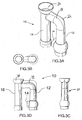
Figure 3A is a perspective view of an example embodiment of the invention; -
Figures 3B top view of the embodiment ofFigure 3A ; -
Figure 3C front view of the embodiment ofFigure 3A ; and -
Figure 3D is a side view of the embodiment ofFigure 3A . - In the example embodiment of the invention, the Device is made of sealed, connected tubular construction resembling a lower case 'h', comprising molded plastic. Other suitable materials may be utilized as desired.
- The
example device 10 is made such that during standard operation it is submerged in liquid with only the off gassingportion 20 protruding above the surface of the liquid. Theexample device 10 may be made such that during non standard operation it can be submerged such that only thediffusion device 14 is under the liquid. This is particularly advantageous when using the device as a pump to transfer liquid. - To achieve the desired goals of infusing gas into the fluid, the
example device 10 can be modularly added onto with as many devices as required, in various configurations and may be suspended in position by any method of securement (such as for example floats and securing brackets to a fixed object in or adjacent the body of water) without affecting its functionality. The example embodiment of the invention includes aflange portion 22 extending above thecross tube portion 18, which acts to provide support to the structure and to assist in locating and securing/bracketing the device against a fixed object as desired. - When operating, the example device imparts gas into the liquid by means of
diffusion device 14 into liquid in theintake tube 12. The rising bubbles of gas drive the liquid in the intake tube portion upwardly, giving the liquid upward velocity. This velocity drives the liquid to the top of the intake tube, across thecross tube 18 and to the top of the offgassing section 20. In the example embodiment shown, thecross tube 18 is angled slightly downwardly from intake tube to discharge tube to facilitate flow of liquid from intake tube to discharge tube portion. - It should be understood that the diffusion device for imparting gas into liquid can be any gas dispersion unit, i.e. airstone, permeable membrane, felt stack etc. The
preferred diffusion device 14 is incorporated into a cap that seals against the device to ensure that no gas escapes the tubular construction. It can be placed in any location in the intake tube, but the further under the surface of the fluid, the greater the velocity the bubble achieves on its accent up the tube and the more energy it imparts to the fluid in the intake tube. - The liquid in the intake tube is pulled from the surrounding fluid body by a low pressure zone due to the rising liquid in the intake tube. This principal is what is noted by the flow of fluids from high to low pressure areas as witnessed by Bernoulli.
- When operating, the diffusion device imparts gas into the intake tube causing a vertical flow of fluid in the example device. If the pressure (in kPa) of gas infused into the liquid is greater or equal to 9.793 x (distance the diffuser is below the fluid line in metres) the device will function. The preferred pressure for any device setup is (9.793 x (distance the diffuser is below the fluid line in metres)) + 13.79kPa. [If the pressure (in PSI) of gas infused into the liquid is greater or equal to ((distance the diffuser is below the fluid line in feet)/(2.31)) the device will function. The preferred pressure for any device setup is ((distance the diffuser is below the fluid line in feet)/(2.31))+2psi]. The example device can be scaled as to accept any flow at these equationed pressures.
- The example embodiment has a bubble reducing device placed in the upper part of the intake tube to reduce the gas bubbles tendency to group together (coalescence). This device can be, but is not limited to, a mesh or other similar series of segregated passages that have the ability to break larger bubbles to smaller ones. The multitude of smaller bubbles in the fluid stream gives a higher probability that the gas in the bubble will transfer to the surrounding fluid. This feature must be placed above the
diffusion device 14 to be effective. - When operating, the example device fills with
fluid 23 to the top of the off gassing portion (as seen inFigure 2 ), which extends above the cross tube portion. This will provide some head differential (in the preferred embodiment a few inches of head differential) to displace the fluid below it in the discharge tube, forcing such fluid out thedischarge opening 26. - The rapidly rising fluid in the intake tube travels to the top of the
intake tube portion 12 and flows across thecross tube portion 18. The energy imparted from the rising bubbles to the fluid is sufficient that the fluid in the cross tube is above the fluid level outside of the pipe. As the fluid passes through the cross tube section, when the fluid gets to the discharge tube/pipe 16 (positioned below the off gas section 20), the head differential causes the fluid in the discharge tube/pipe to be forced down. With this method, a small energy input in the form of gas pressure can be converted into forcing fluid down to great depths as the fluid in the discharge pipe will always try to equalize with the fluid the device is submerged in. - The fluid in the discharge tube/
pipe 16 has a 'downward' velocity due to the head differential above it pushing it down the tube. Because there are still gas bubbles in the fluid stream the downward flow is not laminar. The downward fluid velocity and the tendency of the bubbles to rise cause extreme turbulence in the discharge tube. This turbulence maximizes the time the gas is in contact with the fluid stream enabling extremely efficient transfer of gas from the bubble to the fluid. - Both the inlet tube portion and discharge tube portions are extendable as desired to meet requirements of the device.
- In a pond/lake environment, such as shown by example in
Figure 1 , the example device can successfully take water from the bottom stagnant and septic (hypolimnionic)region 30, bring it to the surface efficiently, off gas the septic causing pollutants (e.g. Phosphorus, Nitrogen, Sulfur etc) and then oxygenate the water and return it to the same strata that it was removed from. - In aquaculture environments, the device can efficiently aerate/oxygenate the water to encourage growth while removing the Nitrogen gasses caused by the fish waste that cause many aquatic diseases.
- In bio growth (algae, larvae etc) the device can infuse any gas into the fluid efficiently and encourage the growth of the desired substance.
- In a wastewater treatment environment, the Device can infuse any gas to encourage the accelerated breakdown of organic material and reduce the BOD & COD pollutant quotient that has negative effects on the environment when discharged above or below the surface.
- The infusion device of the invention has the ability to have extensions attached to the intake and discharge to allow treatment to any depth of waterbody.
- It should be understood that many changes, modifications, variations and other uses and applications will become apparent to those skilled in the art after considering the specification and the accompanying drawings. Therefore, any and all such changes, modifications, variations and other uses and applications which do not depart from the scope of the invention are deemed to be covered by the invention.
Claims (9)
- A device (10) for infusion of gas into fluid, off gassing said fluid and returning said off gassed fluid to a body of fluid, comprising:an intake tube portion (12) having an bottom opening submergable below a body of fluid so as to allow entry of fluid into said intake tube (12);gas diffusion means (14) positioned within said intake tube (12) below the top level of the body of fluid for infusing gas into fluid within said intake tube (12), to allow said gas to be infused into the liquid in said intake tube (12) whereby the rising bubbles of infused gas are sufficient to drive the liquid in the intake tube (12) upwardly to a top portion of the intake tube (12);a cross tube section (18) in communication with said intake tube portion (12), said cross tube section (18) extending to an off gassing section (20) of or above said cross tube section (18);characterized in that the device (10) is configured such that, when submerged to a predetermined depth in the body of fluid, the device (10) fills with fluid to a top of the off gassing section (20) which is located at a level above a surface of the body of fluid and above the cross tube section (18), thereby to generate a head differential;and further characterized by said off gassing section (20) allowing said fluid to have surface exchange with the air and thus removal of gasses from the liquid; anda discharge tube portion (16) communicating with the cross tube section (18), being positioned immediately below said off gas section (20) and extending downwardly therefrom into the body of fluid, whereby the fluid entering the discharge tube (16) has imparted a downward velocity due to the head differential between the liquid at the top of the off gassing section (20), pushing it down the discharge tube (16) and back in the body of fluid.
- A device (10) as claimed in claim 1, wherein:the intake tube portion (12) is vertically oriented;the gas diffusion means (14) is positioned within a bottom portion of said intake tube (12); to allow said gas to be infused into the liquid in said intake tube portion (12) whereby the rising bubbles of infused gas drives the liquid in the intake tube (12) upwardly to a top portion of the intake tube (12) and through the cross tube section (18) in communication with said intake tube portion (12);the cross tube section (18) extends substantially perpendicularly to said intake tube (12) and above said body of fluid to the off gassing section (20);the off gassing section (20) extends above the cross tube section (18); andthe discharge tube portion (16) is vertically oriented.
- A device (10) as claimed in any preceding claim, wherein the pressure in kPa of the diffused gas infused into the fluid is greater than or equal to 9.793 times the distance in metres that the diffusion means is below the fluid line.
- A device as claimed in any preceding claim, wherein the gas diffusion means (14) is located adjacent the bottom opening thereof and the portion of the intake tube (12) including the gas diffusion means (14) and bottom opening is located within the body of fluid, with the remainder of the device (10) above the body of fluid.
- A device (10) as claimed in any preceding claim, wherein the diffusion means (14) is an airstone, permeable membrane or felt stack gas dispersion unit.
- A device (10) as claimed in claim 5, wherein the gas dispersion unit (14) is positioned in a cap that seals against the intake tube portion (12) of device to ensure that no gas escapes.
- A device (10) as claimed in any preceding claim, wherein a bubble reducing device is positioned in the top portion of the intake tube (12), above the diffusion means (14) to reduce the gas bubbles tendency to coalescence.
- A device (10) as claimed in claim 7, wherein the bubble reducing device comprises a plurality of mesh barriers, forming a series of segregated passages.
- A device (10) as claimed in any preceding claim, wherein the device (10) is formed of molded plastic.
Applications Claiming Priority (2)
| Application Number | Priority Date | Filing Date | Title |
|---|---|---|---|
| US1207707P | 2007-12-07 | 2007-12-07 | |
| PCT/CA2008/002136 WO2009070893A1 (en) | 2007-12-07 | 2008-12-05 | Device to infuse gas into liquid |
Publications (3)
| Publication Number | Publication Date |
|---|---|
| EP2225013A1 EP2225013A1 (en) | 2010-09-08 |
| EP2225013A4 EP2225013A4 (en) | 2014-09-03 |
| EP2225013B1 true EP2225013B1 (en) | 2016-06-15 |
Family
ID=40717239
Family Applications (1)
| Application Number | Title | Priority Date | Filing Date |
|---|---|---|---|
| EP08857972.7A Not-in-force EP2225013B1 (en) | 2007-12-07 | 2008-12-05 | Device to infuse gas into liquid |
Country Status (9)
| Country | Link |
|---|---|
| US (1) | US20110187011A1 (en) |
| EP (1) | EP2225013B1 (en) |
| CN (1) | CN101918120B (en) |
| AU (1) | AU2008331399B2 (en) |
| CA (1) | CA2707580C (en) |
| IL (1) | IL206207A (en) |
| MX (1) | MX2010006188A (en) |
| NZ (1) | NZ586096A (en) |
| WO (1) | WO2009070893A1 (en) |
Families Citing this family (4)
| Publication number | Priority date | Publication date | Assignee | Title |
|---|---|---|---|---|
| CN102032220B (en) * | 2010-09-26 | 2015-03-11 | 重庆科技学院 | Push type liquid control device and using method thereof |
| CN103083748B (en) * | 2011-10-31 | 2016-08-31 | 深圳光启高等理工研究院 | A kind of gas liquid exchanger |
| WO2018191276A1 (en) | 2017-04-11 | 2018-10-18 | Grand Shrimp, Llc | Aquaculture systems and methods |
| US10486120B2 (en) * | 2017-04-12 | 2019-11-26 | John T. Vlahogeorge | Floating horizontal aerator for a body of water |
Citations (2)
| Publication number | Priority date | Publication date | Assignee | Title |
|---|---|---|---|---|
| US3840216A (en) * | 1972-10-26 | 1974-10-08 | Clark & Vicario Corp | Vacuum aeration of liquid waste effluent |
| US4278546A (en) * | 1975-10-22 | 1981-07-14 | Imperial Chemical Industries Limited | Treatment of a liquid by circulation and gas contacting |
Family Cites Families (25)
| Publication number | Priority date | Publication date | Assignee | Title |
|---|---|---|---|---|
| US2717774A (en) * | 1951-03-23 | 1955-09-13 | Walker Process Equipment Inc | Nozzle cleaning backflow apparatus |
| US3709363A (en) * | 1970-10-19 | 1973-01-09 | Bio2 Syst Inc | Extended aeration, activated sludge plant |
| CH546708A (en) * | 1972-07-02 | 1974-03-15 | Kaelin J R | PROCEDURE AND DEVICE FOR PURIFYING WASTE WATER. |
| US3794303A (en) * | 1973-06-11 | 1974-02-26 | B Hirshon | Method and apparatus for aerating bodies of water |
| US3994811A (en) * | 1975-06-12 | 1976-11-30 | Harvey Kenneth Cohen | Protein skimmer and carbon filtration replaceable unit |
| US4044720A (en) * | 1976-03-29 | 1977-08-30 | Fast Arlo W | Floating fish rearing system |
| US4337152A (en) * | 1978-09-27 | 1982-06-29 | Frebar Holding Ag | Aeration apparatus and method |
| GB2059790B (en) * | 1979-10-03 | 1983-03-02 | Serck Industries Ltd | Apparatus for combining a liquid and a gas |
| SE446858B (en) * | 1983-05-30 | 1986-10-13 | Atlas Copco Ab | DEVICE FOR OKING THE ACID CONCENTRATION IN A LOWER SURFACE LAYER IN A THERMALLY LAYED WATER BODY |
| US4724086A (en) * | 1986-04-03 | 1988-02-09 | Kortmann Robert W | Apparatus and method for conditioning stratified water bodies |
| JPH06218255A (en) * | 1993-01-27 | 1994-08-09 | Bull- Medical Sci:Kk | Gas-liquid mixing device |
| US5342781A (en) * | 1993-07-15 | 1994-08-30 | Su Wei Wen W | External-loop perfusion air-lift bioreactor |
| US5755976A (en) * | 1996-11-13 | 1998-05-26 | Kortmann; Robert W. | Pneumatic bubble aeration reactor and method of using same |
| US5741443A (en) * | 1996-11-22 | 1998-04-21 | Gemza; Andy | Oxygenation of stratified water |
| JP3455467B2 (en) * | 1999-03-25 | 2003-10-14 | 住友重機械工業株式会社 | Aeration device |
| US6117324A (en) | 1999-05-27 | 2000-09-12 | Clemson University | System and process for treating animal waste |
| WO2001000316A1 (en) * | 1999-06-29 | 2001-01-04 | Sumitomo Metal Industries, Ltd. | Method of dissolving water-soluble gas in sea for isolation into deep sea, device therefor, laying method for device |
| SE518105C2 (en) * | 2000-08-11 | 2002-08-27 | Itt Mfg Enterprises Inc | Methods and apparatus for aerating liquids |
| CN2597472Y (en) * | 2003-01-23 | 2004-01-07 | 浙江大学 | Aerator air water diversion device |
| US7156377B2 (en) * | 2003-05-01 | 2007-01-02 | Chapman Teddie C | Water aeration device and method |
| JP3794489B2 (en) | 2003-06-18 | 2006-07-05 | セイコーエプソン株式会社 | OPTICAL COMMUNICATION MODULE AND METHOD FOR MANUFACTURING THE SAME, OPTICAL COMMUNICATION DEVICE, AND ELECTRONIC DEVICE |
| US7077208B2 (en) * | 2003-09-11 | 2006-07-18 | R3 Pump Technologies | Method and system for directing fluid flow |
| JP2007111573A (en) * | 2004-06-08 | 2007-05-10 | Tetsuhiko Fujisato | Aeration method, its apparatus and its system |
| JP2008200604A (en) * | 2007-02-20 | 2008-09-04 | Fuji Clean Kogyo Kk | Bubble treatment device and water treatment apparatus |
| WO2008140229A2 (en) | 2007-05-10 | 2008-11-20 | Joong Chun Kwon | A settling tank having an aeration part in its inner space |
-
2008
- 2008-12-05 US US12/746,543 patent/US20110187011A1/en not_active Abandoned
- 2008-12-05 MX MX2010006188A patent/MX2010006188A/en active IP Right Grant
- 2008-12-05 CN CN2008801246393A patent/CN101918120B/en not_active Expired - Fee Related
- 2008-12-05 EP EP08857972.7A patent/EP2225013B1/en not_active Not-in-force
- 2008-12-05 NZ NZ58609608A patent/NZ586096A/en not_active IP Right Cessation
- 2008-12-05 CA CA2707580A patent/CA2707580C/en active Active
- 2008-12-05 AU AU2008331399A patent/AU2008331399B2/en not_active Ceased
- 2008-12-05 WO PCT/CA2008/002136 patent/WO2009070893A1/en not_active Ceased
-
2010
- 2010-06-06 IL IL206207A patent/IL206207A/en not_active IP Right Cessation
Patent Citations (2)
| Publication number | Priority date | Publication date | Assignee | Title |
|---|---|---|---|---|
| US3840216A (en) * | 1972-10-26 | 1974-10-08 | Clark & Vicario Corp | Vacuum aeration of liquid waste effluent |
| US4278546A (en) * | 1975-10-22 | 1981-07-14 | Imperial Chemical Industries Limited | Treatment of a liquid by circulation and gas contacting |
Also Published As
| Publication number | Publication date |
|---|---|
| IL206207A (en) | 2013-10-31 |
| EP2225013A1 (en) | 2010-09-08 |
| EP2225013A4 (en) | 2014-09-03 |
| CA2707580C (en) | 2016-02-23 |
| IL206207A0 (en) | 2010-12-30 |
| AU2008331399B2 (en) | 2013-07-25 |
| CN101918120A (en) | 2010-12-15 |
| WO2009070893A1 (en) | 2009-06-11 |
| NZ586096A (en) | 2012-12-21 |
| AU2008331399A1 (en) | 2009-06-11 |
| CA2707580A1 (en) | 2009-06-11 |
| CN101918120B (en) | 2013-07-17 |
| US20110187011A1 (en) | 2011-08-04 |
| MX2010006188A (en) | 2010-09-28 |
Similar Documents
| Publication | Publication Date | Title |
|---|---|---|
| CA2284403C (en) | Device for agitating a liquid in a reactor and for injecting a gas into this liquid | |
| KR100816921B1 (en) | Aeration method, aeration apparatus and aeration system | |
| CA2707580C (en) | Device to infuse gas into liquid | |
| CN107866102A (en) | Floating type water purification system | |
| WO1994006720A1 (en) | Floating nitrification reactor in a treatment pond | |
| US20130220944A1 (en) | Methods and apparatus for aeration of liquid medium and vectoring flow control | |
| US20110096618A1 (en) | Method and apparatus for aeration | |
| KR20180114710A (en) | Apparatus for oxygen supply for water treatment | |
| AU2020266420A1 (en) | Device for transport and treatment of liquid | |
| WO2015061310A1 (en) | Air-powered water circulation systems for ponds | |
| US20210084848A1 (en) | Water system for hydroponic growing | |
| JP4107486B2 (en) | Water treatment equipment | |
| JP2000140823A (en) | Underwater diffuser | |
| JP3418608B2 (en) | Gas-liquid mixing device | |
| JP4238515B2 (en) | Stirring method in methane fermentation water tank and water tank for breeding aquatic organisms such as methane bacteria | |
| US11267735B1 (en) | Circulation pump for vertically circulating water in bodies of water using consecutive expanding super air bubbles | |
| KR101084061B1 (en) | Lake purifier | |
| CN206512001U (en) | A kind of aerator | |
| JPH06343993A (en) | Intermittent air pumping-up method and device for sea water | |
| US20160016831A1 (en) | Top down variable depth aeration system | |
| JP2593799B2 (en) | Sewage inlet in aeration equipment | |
| JP5110876B2 (en) | Aeration method, aeration apparatus and aeration system | |
| JPH06296996A (en) | Floating body water purification device | |
| JP4250895B2 (en) | Oxygen dissolved water supply system | |
| JPH03270796A (en) | Apparatus for purifying water area |
Legal Events
| Date | Code | Title | Description |
|---|---|---|---|
| PUAI | Public reference made under article 153(3) epc to a published international application that has entered the european phase |
Free format text: ORIGINAL CODE: 0009012 |
|
| 17P | Request for examination filed |
Effective date: 20100618 |
|
| AK | Designated contracting states |
Kind code of ref document: A1 Designated state(s): AT BE BG CH CY CZ DE DK EE ES FI FR GB GR HR HU IE IS IT LI LT LU LV MC MT NL NO PL PT RO SE SI SK TR |
|
| AX | Request for extension of the european patent |
Extension state: AL BA MK RS |
|
| DAX | Request for extension of the european patent (deleted) | ||
| RIC1 | Information provided on ipc code assigned before grant |
Ipc: B01F 3/04 20060101AFI20140722BHEP Ipc: F04F 1/00 20060101ALI20140722BHEP |
|
| A4 | Supplementary search report drawn up and despatched |
Effective date: 20140805 |
|
| RIC1 | Information provided on ipc code assigned before grant |
Ipc: F04F 1/00 20060101ALI20140730BHEP Ipc: B01F 3/04 20060101AFI20140730BHEP |
|
| 17Q | First examination report despatched |
Effective date: 20150721 |
|
| GRAP | Despatch of communication of intention to grant a patent |
Free format text: ORIGINAL CODE: EPIDOSNIGR1 |
|
| INTG | Intention to grant announced |
Effective date: 20160111 |
|
| GRAS | Grant fee paid |
Free format text: ORIGINAL CODE: EPIDOSNIGR3 |
|
| GRAA | (expected) grant |
Free format text: ORIGINAL CODE: 0009210 |
|
| AK | Designated contracting states |
Kind code of ref document: B1 Designated state(s): AT BE BG CH CY CZ DE DK EE ES FI FR GB GR HR HU IE IS IT LI LT LU LV MC MT NL NO PL PT RO SE SI SK TR |
|
| REG | Reference to a national code |
Ref country code: CH Ref legal event code: EP Ref country code: GB Ref legal event code: FG4D |
|
| REG | Reference to a national code |
Ref country code: IE Ref legal event code: FG4D |
|
| REG | Reference to a national code |
Ref country code: AT Ref legal event code: REF Ref document number: 806201 Country of ref document: AT Kind code of ref document: T Effective date: 20160715 |
|
| REG | Reference to a national code |
Ref country code: DE Ref legal event code: R096 Ref document number: 602008044748 Country of ref document: DE |
|
| REG | Reference to a national code |
Ref country code: LT Ref legal event code: MG4D |
|
| REG | Reference to a national code |
Ref country code: NL Ref legal event code: MP Effective date: 20160615 |
|
| PG25 | Lapsed in a contracting state [announced via postgrant information from national office to epo] |
Ref country code: LT Free format text: LAPSE BECAUSE OF FAILURE TO SUBMIT A TRANSLATION OF THE DESCRIPTION OR TO PAY THE FEE WITHIN THE PRESCRIBED TIME-LIMIT Effective date: 20160615 Ref country code: FI Free format text: LAPSE BECAUSE OF FAILURE TO SUBMIT A TRANSLATION OF THE DESCRIPTION OR TO PAY THE FEE WITHIN THE PRESCRIBED TIME-LIMIT Effective date: 20160615 Ref country code: NO Free format text: LAPSE BECAUSE OF FAILURE TO SUBMIT A TRANSLATION OF THE DESCRIPTION OR TO PAY THE FEE WITHIN THE PRESCRIBED TIME-LIMIT Effective date: 20160915 |
|
| REG | Reference to a national code |
Ref country code: AT Ref legal event code: MK05 Ref document number: 806201 Country of ref document: AT Kind code of ref document: T Effective date: 20160615 |
|
| PG25 | Lapsed in a contracting state [announced via postgrant information from national office to epo] |
Ref country code: SE Free format text: LAPSE BECAUSE OF FAILURE TO SUBMIT A TRANSLATION OF THE DESCRIPTION OR TO PAY THE FEE WITHIN THE PRESCRIBED TIME-LIMIT Effective date: 20160615 Ref country code: LV Free format text: LAPSE BECAUSE OF FAILURE TO SUBMIT A TRANSLATION OF THE DESCRIPTION OR TO PAY THE FEE WITHIN THE PRESCRIBED TIME-LIMIT Effective date: 20160615 Ref country code: GR Free format text: LAPSE BECAUSE OF FAILURE TO SUBMIT A TRANSLATION OF THE DESCRIPTION OR TO PAY THE FEE WITHIN THE PRESCRIBED TIME-LIMIT Effective date: 20160916 Ref country code: NL Free format text: LAPSE BECAUSE OF FAILURE TO SUBMIT A TRANSLATION OF THE DESCRIPTION OR TO PAY THE FEE WITHIN THE PRESCRIBED TIME-LIMIT Effective date: 20160615 Ref country code: HR Free format text: LAPSE BECAUSE OF FAILURE TO SUBMIT A TRANSLATION OF THE DESCRIPTION OR TO PAY THE FEE WITHIN THE PRESCRIBED TIME-LIMIT Effective date: 20160615 |
|
| PG25 | Lapsed in a contracting state [announced via postgrant information from national office to epo] |
Ref country code: RO Free format text: LAPSE BECAUSE OF FAILURE TO SUBMIT A TRANSLATION OF THE DESCRIPTION OR TO PAY THE FEE WITHIN THE PRESCRIBED TIME-LIMIT Effective date: 20160615 Ref country code: IT Free format text: LAPSE BECAUSE OF FAILURE TO SUBMIT A TRANSLATION OF THE DESCRIPTION OR TO PAY THE FEE WITHIN THE PRESCRIBED TIME-LIMIT Effective date: 20160615 Ref country code: EE Free format text: LAPSE BECAUSE OF FAILURE TO SUBMIT A TRANSLATION OF THE DESCRIPTION OR TO PAY THE FEE WITHIN THE PRESCRIBED TIME-LIMIT Effective date: 20160615 Ref country code: IS Free format text: LAPSE BECAUSE OF FAILURE TO SUBMIT A TRANSLATION OF THE DESCRIPTION OR TO PAY THE FEE WITHIN THE PRESCRIBED TIME-LIMIT Effective date: 20161015 Ref country code: SK Free format text: LAPSE BECAUSE OF FAILURE TO SUBMIT A TRANSLATION OF THE DESCRIPTION OR TO PAY THE FEE WITHIN THE PRESCRIBED TIME-LIMIT Effective date: 20160615 Ref country code: CZ Free format text: LAPSE BECAUSE OF FAILURE TO SUBMIT A TRANSLATION OF THE DESCRIPTION OR TO PAY THE FEE WITHIN THE PRESCRIBED TIME-LIMIT Effective date: 20160615 |
|
| PG25 | Lapsed in a contracting state [announced via postgrant information from national office to epo] |
Ref country code: BE Free format text: LAPSE BECAUSE OF FAILURE TO SUBMIT A TRANSLATION OF THE DESCRIPTION OR TO PAY THE FEE WITHIN THE PRESCRIBED TIME-LIMIT Effective date: 20160615 Ref country code: ES Free format text: LAPSE BECAUSE OF FAILURE TO SUBMIT A TRANSLATION OF THE DESCRIPTION OR TO PAY THE FEE WITHIN THE PRESCRIBED TIME-LIMIT Effective date: 20160615 Ref country code: PT Free format text: LAPSE BECAUSE OF FAILURE TO SUBMIT A TRANSLATION OF THE DESCRIPTION OR TO PAY THE FEE WITHIN THE PRESCRIBED TIME-LIMIT Effective date: 20161017 Ref country code: PL Free format text: LAPSE BECAUSE OF FAILURE TO SUBMIT A TRANSLATION OF THE DESCRIPTION OR TO PAY THE FEE WITHIN THE PRESCRIBED TIME-LIMIT Effective date: 20160615 Ref country code: AT Free format text: LAPSE BECAUSE OF FAILURE TO SUBMIT A TRANSLATION OF THE DESCRIPTION OR TO PAY THE FEE WITHIN THE PRESCRIBED TIME-LIMIT Effective date: 20160615 |
|
| REG | Reference to a national code |
Ref country code: DE Ref legal event code: R097 Ref document number: 602008044748 Country of ref document: DE |
|
| PLBE | No opposition filed within time limit |
Free format text: ORIGINAL CODE: 0009261 |
|
| STAA | Information on the status of an ep patent application or granted ep patent |
Free format text: STATUS: NO OPPOSITION FILED WITHIN TIME LIMIT |
|
| 26N | No opposition filed |
Effective date: 20170316 |
|
| PG25 | Lapsed in a contracting state [announced via postgrant information from national office to epo] |
Ref country code: DK Free format text: LAPSE BECAUSE OF FAILURE TO SUBMIT A TRANSLATION OF THE DESCRIPTION OR TO PAY THE FEE WITHIN THE PRESCRIBED TIME-LIMIT Effective date: 20160615 |
|
| REG | Reference to a national code |
Ref country code: DE Ref legal event code: R119 Ref document number: 602008044748 Country of ref document: DE |
|
| REG | Reference to a national code |
Ref country code: CH Ref legal event code: PL |
|
| PG25 | Lapsed in a contracting state [announced via postgrant information from national office to epo] |
Ref country code: SI Free format text: LAPSE BECAUSE OF FAILURE TO SUBMIT A TRANSLATION OF THE DESCRIPTION OR TO PAY THE FEE WITHIN THE PRESCRIBED TIME-LIMIT Effective date: 20160615 |
|
| PG25 | Lapsed in a contracting state [announced via postgrant information from national office to epo] |
Ref country code: MC Free format text: LAPSE BECAUSE OF FAILURE TO SUBMIT A TRANSLATION OF THE DESCRIPTION OR TO PAY THE FEE WITHIN THE PRESCRIBED TIME-LIMIT Effective date: 20160615 |
|
| REG | Reference to a national code |
Ref country code: FR Ref legal event code: ST Effective date: 20170831 |
|
| REG | Reference to a national code |
Ref country code: IE Ref legal event code: MM4A |
|
| PG25 | Lapsed in a contracting state [announced via postgrant information from national office to epo] |
Ref country code: CH Free format text: LAPSE BECAUSE OF NON-PAYMENT OF DUE FEES Effective date: 20161231 Ref country code: LU Free format text: LAPSE BECAUSE OF NON-PAYMENT OF DUE FEES Effective date: 20161205 Ref country code: LI Free format text: LAPSE BECAUSE OF NON-PAYMENT OF DUE FEES Effective date: 20161231 Ref country code: FR Free format text: LAPSE BECAUSE OF NON-PAYMENT OF DUE FEES Effective date: 20170102 |
|
| PG25 | Lapsed in a contracting state [announced via postgrant information from national office to epo] |
Ref country code: DE Free format text: LAPSE BECAUSE OF NON-PAYMENT OF DUE FEES Effective date: 20170701 Ref country code: IE Free format text: LAPSE BECAUSE OF NON-PAYMENT OF DUE FEES Effective date: 20161205 |
|
| PGFP | Annual fee paid to national office [announced via postgrant information from national office to epo] |
Ref country code: GB Payment date: 20171228 Year of fee payment: 10 |
|
| PG25 | Lapsed in a contracting state [announced via postgrant information from national office to epo] |
Ref country code: CY Free format text: LAPSE BECAUSE OF FAILURE TO SUBMIT A TRANSLATION OF THE DESCRIPTION OR TO PAY THE FEE WITHIN THE PRESCRIBED TIME-LIMIT Effective date: 20160615 Ref country code: HU Free format text: LAPSE BECAUSE OF FAILURE TO SUBMIT A TRANSLATION OF THE DESCRIPTION OR TO PAY THE FEE WITHIN THE PRESCRIBED TIME-LIMIT; INVALID AB INITIO Effective date: 20081205 |
|
| PG25 | Lapsed in a contracting state [announced via postgrant information from national office to epo] |
Ref country code: TR Free format text: LAPSE BECAUSE OF FAILURE TO SUBMIT A TRANSLATION OF THE DESCRIPTION OR TO PAY THE FEE WITHIN THE PRESCRIBED TIME-LIMIT Effective date: 20160615 |
|
| PG25 | Lapsed in a contracting state [announced via postgrant information from national office to epo] |
Ref country code: BG Free format text: LAPSE BECAUSE OF FAILURE TO SUBMIT A TRANSLATION OF THE DESCRIPTION OR TO PAY THE FEE WITHIN THE PRESCRIBED TIME-LIMIT Effective date: 20160615 |
|
| PG25 | Lapsed in a contracting state [announced via postgrant information from national office to epo] |
Ref country code: MT Free format text: LAPSE BECAUSE OF NON-PAYMENT OF DUE FEES Effective date: 20161205 |
|
| GBPC | Gb: european patent ceased through non-payment of renewal fee |
Effective date: 20181205 |
|
| PG25 | Lapsed in a contracting state [announced via postgrant information from national office to epo] |
Ref country code: GB Free format text: LAPSE BECAUSE OF NON-PAYMENT OF DUE FEES Effective date: 20181205 |