EP2224869B1 - Double collet connector assembly for bone anchoring element - Google Patents
Double collet connector assembly for bone anchoring element Download PDFInfo
- Publication number
- EP2224869B1 EP2224869B1 EP08857440A EP08857440A EP2224869B1 EP 2224869 B1 EP2224869 B1 EP 2224869B1 EP 08857440 A EP08857440 A EP 08857440A EP 08857440 A EP08857440 A EP 08857440A EP 2224869 B1 EP2224869 B1 EP 2224869B1
- Authority
- EP
- European Patent Office
- Prior art keywords
- double collet
- connector assembly
- wedge surface
- outer closure
- connector
- Prior art date
- Legal status (The legal status is an assumption and is not a legal conclusion. Google has not performed a legal analysis and makes no representation as to the accuracy of the status listed.)
- Not-in-force
Links
- 210000000988 bone and bone Anatomy 0.000 title claims abstract description 31
- 238000004873 anchoring Methods 0.000 title claims abstract description 28
- 241000722921 Tulipa gesneriana Species 0.000 description 6
- 239000000463 material Substances 0.000 description 6
- 230000008878 coupling Effects 0.000 description 3
- 238000010168 coupling process Methods 0.000 description 3
- 238000005859 coupling reaction Methods 0.000 description 3
- 239000004696 Poly ether ether ketone Substances 0.000 description 2
- 238000007373 indentation Methods 0.000 description 2
- 230000000399 orthopedic effect Effects 0.000 description 2
- 229920002530 polyetherether ketone Polymers 0.000 description 2
- 229910000684 Cobalt-chrome Inorganic materials 0.000 description 1
- 229910001069 Ti alloy Inorganic materials 0.000 description 1
- RTAQQCXQSZGOHL-UHFFFAOYSA-N Titanium Chemical compound [Ti] RTAQQCXQSZGOHL-UHFFFAOYSA-N 0.000 description 1
- 229910045601 alloy Inorganic materials 0.000 description 1
- 239000000956 alloy Substances 0.000 description 1
- 239000003242 anti bacterial agent Substances 0.000 description 1
- 229940088710 antibiotic agent Drugs 0.000 description 1
- 230000000712 assembly Effects 0.000 description 1
- 238000000429 assembly Methods 0.000 description 1
- 230000000903 blocking effect Effects 0.000 description 1
- 210000000078 claw Anatomy 0.000 description 1
- 230000006835 compression Effects 0.000 description 1
- 238000007906 compression Methods 0.000 description 1
- 238000010276 construction Methods 0.000 description 1
- 229910052588 hydroxylapatite Inorganic materials 0.000 description 1
- 239000007943 implant Substances 0.000 description 1
- 229910052751 metal Inorganic materials 0.000 description 1
- 239000002184 metal Substances 0.000 description 1
- 238000012986 modification Methods 0.000 description 1
- 230000004048 modification Effects 0.000 description 1
- XYJRXVWERLGGKC-UHFFFAOYSA-D pentacalcium;hydroxide;triphosphate Chemical compound [OH-].[Ca+2].[Ca+2].[Ca+2].[Ca+2].[Ca+2].[O-]P([O-])([O-])=O.[O-]P([O-])([O-])=O.[O-]P([O-])([O-])=O XYJRXVWERLGGKC-UHFFFAOYSA-D 0.000 description 1
- 239000004033 plastic Substances 0.000 description 1
- 229920000642 polymer Polymers 0.000 description 1
- 229910001285 shape-memory alloy Inorganic materials 0.000 description 1
- 239000007787 solid Substances 0.000 description 1
- 229910001256 stainless steel alloy Inorganic materials 0.000 description 1
- 239000000126 substance Substances 0.000 description 1
- 238000001356 surgical procedure Methods 0.000 description 1
- 239000010936 titanium Substances 0.000 description 1
- 229910052719 titanium Inorganic materials 0.000 description 1
Images


Classifications
-
- A—HUMAN NECESSITIES
- A61—MEDICAL OR VETERINARY SCIENCE; HYGIENE
- A61B—DIAGNOSIS; SURGERY; IDENTIFICATION
- A61B17/00—Surgical instruments, devices or methods
- A61B17/56—Surgical instruments or methods for treatment of bones or joints; Devices specially adapted therefor
- A61B17/58—Surgical instruments or methods for treatment of bones or joints; Devices specially adapted therefor for osteosynthesis, e.g. bone plates, screws or setting implements
- A61B17/68—Internal fixation devices, including fasteners and spinal fixators, even if a part thereof projects from the skin
- A61B17/70—Spinal positioners or stabilisers, e.g. stabilisers comprising fluid filler in an implant
- A61B17/7001—Screws or hooks combined with longitudinal elements which do not contact vertebrae
- A61B17/7035—Screws or hooks, wherein a rod-clamping part and a bone-anchoring part can pivot relative to each other
- A61B17/7037—Screws or hooks, wherein a rod-clamping part and a bone-anchoring part can pivot relative to each other wherein pivoting is blocked when the rod is clamped
-
- A—HUMAN NECESSITIES
- A61—MEDICAL OR VETERINARY SCIENCE; HYGIENE
- A61B—DIAGNOSIS; SURGERY; IDENTIFICATION
- A61B17/00—Surgical instruments, devices or methods
- A61B17/56—Surgical instruments or methods for treatment of bones or joints; Devices specially adapted therefor
- A61B17/58—Surgical instruments or methods for treatment of bones or joints; Devices specially adapted therefor for osteosynthesis, e.g. bone plates, screws or setting implements
- A61B17/68—Internal fixation devices, including fasteners and spinal fixators, even if a part thereof projects from the skin
- A61B17/70—Spinal positioners or stabilisers, e.g. stabilisers comprising fluid filler in an implant
- A61B17/7001—Screws or hooks combined with longitudinal elements which do not contact vertebrae
- A61B17/7032—Screws or hooks with U-shaped head or back through which longitudinal rods pass
Definitions
- the present invention seeks to provide an improved connector assembly for connecting rods and the like to bone anchoring elements, such as pedicle screws, as is described more in detail hereinbelow.
- the connector assembly of the invention permits rotational and translational adjustments before locking the rod in place.
- the connector assembly of the invention includes a double collet assembly with enhanced wedging force.
Landscapes
- Health & Medical Sciences (AREA)
- Orthopedic Medicine & Surgery (AREA)
- Life Sciences & Earth Sciences (AREA)
- Neurology (AREA)
- Surgery (AREA)
- Heart & Thoracic Surgery (AREA)
- Engineering & Computer Science (AREA)
- Biomedical Technology (AREA)
- Nuclear Medicine, Radiotherapy & Molecular Imaging (AREA)
- Medical Informatics (AREA)
- Molecular Biology (AREA)
- Animal Behavior & Ethology (AREA)
- General Health & Medical Sciences (AREA)
- Public Health (AREA)
- Veterinary Medicine (AREA)
- Surgical Instruments (AREA)
Abstract
Description
- The present invention relates generally to anchoring structures for orthopedic devices, and particularly to a connector assembly for connecting rods and the like to bone anchoring elements, such as pedicle screws.
- Many spinal fixation systems are found in the prior art for fixing connecting rods and the like to pedicle screws. Some systems have a disadvantage in that the rod must be bent after coupling to the pedicle screw because of anatomical considerations. Some systems attempt to solve this problem with different kinds of connectors that secure the rod to a polyaxial pedicle screw head and permit spatial adjustments before locking the rod in place. It is imperative to lock the connecting rod with respect to the pedicle screw (or any other kind of bone anchoring element) in order to prevent loosening of the spinal fixation system that could have undesirable consequences to the patient. Nevertheless, no design is free of problems and there is still a need for a connector that is "user- friendly" and permits adjustments before locking the rod in place.
-
US 2007/0118123 A1 discloses a polyaxial bone anchor having a locking element shaped and configured to allow an anchoring member (e.g. a screw) to polyaxially rotate about a central axis of the bone anchor before compression locking the anchoring member within an anchor head. -
US 2006/0276792 discloses a pedicle screw, a rod assembly and a tulip assembly. In particular, a threaded portion of the screw can be affixed to a bone of a patient during spine surgery. The tulip assembly includes a tulip positioned on the head portion of the screw and a fastener assembly can fasten the tulip on the head portion. A rod retainer member is positioned inside the tulip and grips the rod to hold it in position relative to the tulip assembly and pedicle screw. -
US 5,882,350 discloses a polyaxial orthopedic device for use with a rod implant apparatus, the device including a screw having a curvate head and a two piece interlocking coupling element which mounts about the curvate head. The two piece interlocking coupling may have a socket portion and a cap portion having vertical slots. -
US 2007/0049933 A1 discloses a multi-axial spinal pedicle screw engaged with a spinal rod and inserted into and fixed to a pedicle. The screw includes: a screw rod in which a spherical articulation is integrally formed at an upper portion thereof, the screw rod being inserted into and fixed to the pedicle through a screw thread formed on the outer surface of a lower portion thereof; a spherical chuck having a plurality of claws, for surrounding and fixing the spherical articulation; a head section in which a receiving hole for receiving the spherical chuck fixing the spherical articulation is formed at a lower portion thereof so as to penetrate the lower portion, a rod receiving channel for receiving the spinal rod is opened upward, and an engagement screw root is formed on the inner surface of the rod receiving channel; and a tightening screw in which an engagement screw thread corresponding to the engagement screw root is formed on the outer surface thereof, the tightening screw being engaged with the head section through the rod receiving channel to fix the spinal rod. -
WO 2006/116437 A2 discloses a bone anchor for attaching a rod to a bone having an anchor head with a U-shaped opening for receiving the rod. The bone anchor also includes a locking cap having a main body and a set screw. - The present invention seeks to provide an improved connector assembly for connecting rods and the like to bone anchoring elements, such as pedicle screws, as is described more in detail hereinbelow. The connector assembly of the invention permits rotational and translational adjustments before locking the rod in place. The connector assembly of the invention includes a double collet assembly with enhanced wedging force.
- There is thus provided in accordance with the present invention a connector assembly according to claim 1, including a bone anchoring element including a spherical head, a double collet that includes an inner clamping portion, a first wedge surface and a second wedge surface, an outer closure element that includes an inner clamping portion that corresponds in shape to an outer contour of the double collet, the outer closure element including a pair of arms that define a channel shaped for receiving therein a connector element, and an interface ring that includes a base formed with an inner wedge surface and a pair of wing extensions that extend from the base, wherein the double collet behaves as a spring element formed with a single continuous spiral groove or a single continuous groove comprising a plurality of circumferential grooves connected by axial grooves or a single continuous spiral notch.
- In accordance with an embodiment of the present invention the inner clamping portion of the double collet is placed over the spherical head of the bone anchoring element, the interface ring is placed over the double collet so that the inner wedge surface sits against the first wedge surface, the outer closure element is placed over the interface ring and the double collet, wherein the inner clamping portion of the outer closure element abuts against the second wedge surface, and the connector element is placed in the channel of the outer closure element, and wherein the connector assembly further includes a cap member which is tightened against the connector element, which forces the connector element against the interface ring, which presses against the first wedge surface of the double collet, thereby causing the second wedge surface to be wedged between the outer closure element and the spherical head and also presses the first wedge surface onto the spherical head so that the double collet firmly grips the spherical head of the bone anchoring element.
- Further in accordance with an embodiment of the present invention the connector element does not contact the spherical head of the bone anchoring element. The first and second wedge surfaces may be conical in shape. The inner clamping portion may be formed by inner surfaces of a plurality of resilient fingers, wherein the resilient fingers define the first and second wedge surfaces, and wherein the resilient fingers are separated from each other by grooves formed in the double collet.
- The upper portion of the arms of the outer closure element may be threaded and the cap member may threadingly mate with the upper portion. The wing extensions may have inner sloping surfaces.
- The present invention will be understood and appreciated more fully from the following detailed description taken in conjunction with the drawings in which:
-
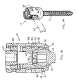
Figs. 1A and 1B are simplified pictorial and sectional illustrations, respectively, of a connector assembly for a bone anchoring element, showing a double collet which is not part of the present invention; -
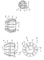
Figs. 2A, 2B, 2C and 2D are simplified pictorial, top view, sectional and side-view illustrations, respectively, of a double collet of the connector assembly ofFigs. 1A-1 B which is not part of the present invention; -
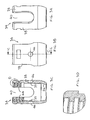
Figs. 3A, 3B, 3C and 3D are simplified front view, side view, sectional and thread detail view illustrations, respectively, of an outer closure element of the connector assembly ofFigs. 1A-1B , constructed and operative in accordance with an embodiment of the present invention; -
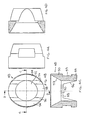
Figs. 4A, 4B and 4C are simplified pictorial, top-view, side sectional and front sectional illustrations, respectively, of an interface ring of the connector assembly ofFigs. 1A-1B , constructed and operative in accordance with another embodiment of the present invention; -
Figs. 5A, 5B, 5C and 5D are simplified pictorial, top view, sectional and thread detail view illustrations, respectively, of a cap element of the connector assembly ofFigs. 1A-1B , constructed and operative in accordance with an embodiment of the present invention; -
Fig. 6 is a simplified illustration of a double collet which is not part of the present invention, made of separate pieces; -
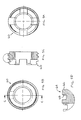
Figs. 7A-7B are simplified illustrations of a double collet, constructed and operative in accordance with an embodiment of the present invention, formed with a spiral groove; -
Fig. 7C is a simplified illustration of another double collet, constructed and operative in accordance with another embodiment of the present invention, formed with one single continuous groove comprising a plurality of circumferential grooves connected by axial grooves; and -
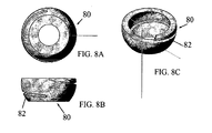
Figs. 8A-8C are simplified illustrations of a double collet, constructed and operative in accordance with another embodiment of the present invention, formed with a spiral notch. - Reference is now made to
Figs. 1A-1B , which illustrate aconnector assembly 10 for abone anchoring element 12 comprising adouble collet 18 which is not part of the present invention. - In a non-limiting embodiment of the invention, the
bone anchoring element 12 includes a threaded mechanical fastener (for example, without limitation, a pedicle screw, a pedicle anchor device, a blocking screw for a pedicle anchoring device or any other device for attachment to the pedicle, vertebral body or any other bone) having a spherical proximal portion 14 (also referred to as a spherical head 14) and a (pointed) distal portion 16. Alternatively,bone anchoring element 12 can be a hook or other mechanical fastener with a spherical head. Thespherical head 14 may be formed with a socket for an Allen wrench or the like. - Reference is now made additionally to
Figs. 2A-2D which are not part of the present invention. Theconnector assembly 10 includes adouble collet 18 that includes aninner clamping portion 20, formed by inner surfaces of a plurality of resilient fingers 22 (also referred to as tabs, leaves or petals, these terms and the like being used interchangeably) spaced around alongitudinal axis 24 thereof.Resilient fingers 22 are separated from each other and are formed by cuts orgrooves 26 formed indouble collet 18. The plurality ofresilient fingers 22 ofdouble collet 18 define two wedge surfaces 30 (first orupper wedge surface 30 in the sense of the drawing) and 32 (second or lower wedge surface 32). The wedge surfaces are angled with respect to each other and are preferably conical in shape. Clampingportion 20 resiliently clamps onspherical head 14 ofbone anchoring element 12. - Reference is now made additionally to
Figs. 3A-3D . Theconnector assembly 10 may include anouter closure element 34 that includes an inner clamping portion 36 (Fig. 3C ). Theinner clamping portion 36 is preferably conical in shape, and corresponds to the outer conical contour ofsecond wedge surface 32 ofdouble collet 18.Outer closure element 34 may include a pair ofarms 38 that define a channel 40 (Figs. 3A and 3C ), shaped to receive therein a connector element 42 (Figs. 1A-1B ).Channel 40 is preferably U-shaped, but other shapes are possible. An upper portion 44 (Fig. 3C ) ofarms 38 may be threaded. A pair of diametrically-opposedblind holes 46 may be formed on the outside ofarms 38 so as to createinner dimples 39.Holes 46 may also be used for graspingouter closure element 34 with a grasping tool. - Reference is now made additionally to
Figs. 4A-4D . Theconnector assembly 10 may include aninterface ring 48.Interface ring 48 may include around base 50 with a hole 52 axially bored therethrough.Base 50 is formed with aninner wedge surface 53, formed such as by countersinking a conical surface. A pair ofwing extensions 54 extend (upward in the sense ofFig. 4A ) frombase 50. Thewing extensions 54 have inner sloping surfaces 56. A generally flatupper portion 58 ofbase 50 separates thewing extensions 54 from one another.Interface ring 48 may also be formed with a pair of diametrically- opposedflat indentations 59. During assembly ofconnector assembly 10, dimples 39 ofouter closure element 34 are received ("click") inindentations 59. - The
connector assembly 10 may be constructed of any suitable, medically safe material, such as but not limited to, stainless steel alloy (e.g., AISI 316L), titanium or titanium alloy or chrome cobalt alloy, PEEK (polyetheretherketone), shape memory alloys or polymers, including resorbable materials, or any combination of the above. Any material may be coated, such as with HA (hydroxyapatite), any factors or substances including active or passive antibiotics, etc. Different parts ofconnector assembly 10 may be constructed of different materials with different resilience or hardness, or of the same material but treated to have different resilience or hardness. - The
connector element 42 is illustrated as a rod with a cylindrical cross section. However, the invention is not limited to this construction, andconnector element 40 may be any slender elongate element, such as but not limited to, a bar of hexagonal, rectangular or square cross section, a rod of elliptical cross section, and many others. - Assembly of
connector assembly 10 is straightforward and easy. Referring toFig. 1B , after bone anchoring element 12 (e.g., pedicle screw) is in place, the user places theinner clamping portion 20 ofdouble collet 18 overspherical head 14 ofbone anchoring element 12.Interface ring 48 is then placed overdouble collet 18 so that theinner wedge surface 53 sits against the first (upper)wedge surface 30 ofresilient fingers 22. Theouter closure element 34 is then placed overinterface ring 48 anddouble collet 18. Theinner clamping portion 36 ofouter closure element 34 abuts against the second (lower)wedge surface 32 ofresilient fingers 22. At this point, the hexagonal socket ofspherical head 14 is still accessible for tightening with a wrench or other tool, because all the parts of the connector assembly have through holes for accessingspherical head 14. - The
connector element 42 is then placed inU-shaped channel 40 ofouter closure element 34. It is noted thatconnector element 42 also passes through the gap betweenarms 54 ofinterface ring 48. It is further noted that theupper portion 58 ofbase 50 is slightly higher than the bottom ofU-shaped channel 40 so thatconnector element 42 abuts againstbase 50 ofinterface ring 48 and not againstouter closure element 34. A threadedcap member 60 is then screwed on theupper portion 44 ofarms 38 ofouter closure element 34.Cap member 60 is tightened againstconnector element 42. This forcesconnector element 40 against theupper portion 58 ofbase 50 ofinterface ring 48, which slides on and presses downwards (in the sense of the drawing) against thefirst wedge surface 30 ofresilient fingers 22 ofdouble collet 18. This downward force has two wedging actions. First, the downward force causes thesecond wedge surface 32 to be wedged betweenouter closure element 34 andspherical head 14. This squeezes and clamps the lower portion of resilient fingers 22 (second wedge surface 32) ontospherical head 14 ofbone anchoring element 12. Second, the downward force presses the upper portion of resilient fingers 22 (first wedge surface 30) onto the top ofspherical head 14 ofbone anchoring element 12. The double clamping action makes thedouble collet 18 firmly gripspherical head 14 ofbone anchoring element 12. There is no contact betweenconnector element 42 andspherical head 14 ofbone anchoring element 12. Anauxiliary cap element 62 may be threadedly received in inner threads ofcap member 60. Theauxiliary cap element 62 may be used to further clamp down onconnector element 42 and provide a fine adjustment of the force thereupon. - Reference is now made additionally to
Figs. 5A-5D . Instead of convention threads,cap element 60 may be formed with athread 64 that comprises oneflat side 66 and anopposite side 68 which is not parallel toflat side 66 but is angled about 10[deg.] thereto. This specially formedthread 64, when tightened in complimentary female threads formed in upper portion 44 (Fig. 3C ) ofarms 38 ofouter closure element 34, tends to pullarms 38 inwards. This preventscap element 60 from tending to force thearms 38 outwards, which would play against the desired tightening force onconnector element 42. - Reference is now made to
Figs. 6-8C , which illustrate other variations of the double collet for the connector assembly, whereasFig. 6 is not part of the present invention. -
Fig. 6 illustrates adouble collet 70, which differs from the previously described double collets in several aspects and is not part of the present invention.Double collet 70 is made of two or more separate pieces, such as, but not limited to, an upper half 71 and alower half 72. (Double collet 70 could alternatively be constructed of right and left halves, slanted pieces, circumferential slices and other shaped pieces.) Furthermore, the upper half 71 ofdouble collet 70 is not conical, but instead spherical. Accordingly, aninterface ring 73 is provided similar tointerface ring 48 but with an internal spherical shape to clamp and wedge on the upper half 71 ofdouble collet 70. The other parts of the assembly may be as described hereinabove. -
Figs. 7A-7B illustrate adouble collet 74, which is formed with aspiral groove 75, thereby makingdouble collet 74 behave as a spring element. The resilience of the spring element is useful in wedging the parts together in the assembly.Double collet 74 is not conical, but instead spherical. Accordingly, interface ring 73 (Fig. 7B ) can be used withdouble collet 74. The other parts of the assembly may be as described hereinabove. It is noted thatspiral groove 75 is one single continuous groove. The groove may be open or closed at the top of the double collet, and may be open or closed at the bottom of the double collet. -
Fig. 7C illustrates anotherdouble collet 76. Instead of the spiral groove ofdouble collet 74,double collet 76 is formed with one single continuous groove comprising a plurality ofcircumferential grooves 77 connected byaxial grooves 78, thereby makingdouble collet 76 behave as a spring element useful in wedging the parts together in the assembly.Double collet 76 is illustrated as conical, but could alternatively be spherical.Figs. 8A-8C illustrate adouble collet 80, which is formed with a singlecontinuous spiral notch 82. Unlike thespiral groove 75 ofdouble collet 74 which goes through the entire thickness of the collet wall,spiral notch 82 is "blind", that is, does not go through the entire thickness of the collet wall.Double collet 80 is spherical. The notch may be open or closed at the top of the double collet, and may be open or closed at the bottom of the double collet. - Another possibility of carrying out the invention is to use a double collet made of a solid, single piece (conical or spherical or other shapes), which is constructed of a thin, crushable material (e.g., thin metal or plastic). The deformation of the double collet provides the necessary wedging.
- The connector assemblies of the invention permit rotational adjustments with respect to the spherical head of the bone anchoring element and translational adjustments of the connector element before locking the connector element in place.
- It will be appreciated by persons skilled in the art that the present invention is not limited by what has been particularly shown and described hereinabove. Rather the scope of the present invention includes both combinations and subcombinations of the features described hereinabove as well as modifications and variations thereof which would occur to a person of skill in the art upon reading the foregoing description and which are not in the prior art.
Claims (8)
- A connector assembly (10) comprising:a bone anchoring element (12) comprising a spherical head (14);a double collet (74, 76, 80) that comprises an inner clamping portion (20), a first wedge surface (30) and a second wedge surface (32);an outer closure element (34) that comprises an inner clamping portion (36) that corresponds in shape to an outer contour of said double collet (74, 76, 80), said outer closure element (34) comprising a pair of arms (38) that define a channel (40) shaped for receiving therein a connector element (42); andan interface ring (48) that comprises a base (50) formed with an inner wedge surface (53) and a pair of wing extensions (54) that extend from said base (50);characterized in that said double collet (74, 76, 80) behaves as a spring element formed with a single continuous spiral groove (75) or a single continuous groove comprising a plurality of circumferential grooves (77) connected by axial grooves (78) or a single continuous spiral notch (82).
- The connector assembly (10) according to claim 1, wherein said inner clamping portion (36) of said double collet is placed over said spherical head (14) of said bone anchoring element (12), said interface ring (48) is placed over said double collet so that said inner wedge surface (53) sits against said first wedge surface (30), said outer closure element (34) is placed over said interface ring (48) and said double collet, wherein said inner clamping portion (36) of said outer closure element (34) abuts against said second wedge surface (32), and said connector element (42) is placed in said channel (40) of said outer closure element (34), and wherein said connector assembly further comprises a cap member (60) which is tightened against said connector element (42), which forces said connector element (42) against said interface ring (48), which presses against said first wedge surface (30) of said double collet, thereby causing said second wedge surface (32) to be wedged between said outer closure element (34) and said spherical head (14) and also presses said first wedge surface (30) onto said spherical head (14) so that said double collet firmly grips said spherical head (14) of said bone anchoring element (12).
- The connector assembly according to claim 1, wherein said first and second wedge surfaces (30, 32) are conical in shape.
- The connector assembly according to claim 1, wherein said first and second wedge surfaces (30, 32) are spherical in shape.
- The connector assembly according to claim 1, wherein said inner clamping portion (36) is formed by inner surfaces of a plurality of resilient fingers (22), the resilient fingers (22) defining said first and second wedge surfaces (30, 32), and wherein said resilient fingers (22) are separated from each other by grooves (26) formed in said double collet.
- The connector assembly according to claim 1, wherein an upper portion of said arms (38) of said outer closure element (34) is threaded and said cap member (60) threadingly mates with said upper portion.
- The connector assembly according to claim 1, wherein said wing extensions (54) having inner sloping surfaces.
- The connector assembly according to claim 2, wherein an upper portion of said base of said interface ring (48) is higher than a bottom of said channel (40).
Applications Claiming Priority (2)
| Application Number | Priority Date | Filing Date | Title |
|---|---|---|---|
| US11/949,916 US7789900B2 (en) | 2007-12-04 | 2007-12-04 | Double collet connector assembly for bone anchoring element |
| PCT/IL2008/001576 WO2009072125A1 (en) | 2007-12-04 | 2008-12-04 | Double collet connector assembly for bone anchoring element |
Publications (2)
| Publication Number | Publication Date |
|---|---|
| EP2224869A1 EP2224869A1 (en) | 2010-09-08 |
| EP2224869B1 true EP2224869B1 (en) | 2011-09-14 |
Family
ID=40511026
Family Applications (1)
| Application Number | Title | Priority Date | Filing Date |
|---|---|---|---|
| EP08857440A Not-in-force EP2224869B1 (en) | 2007-12-04 | 2008-12-04 | Double collet connector assembly for bone anchoring element |
Country Status (4)
| Country | Link |
|---|---|
| US (1) | US7789900B2 (en) |
| EP (1) | EP2224869B1 (en) |
| AT (1) | ATE524123T1 (en) |
| WO (1) | WO2009072125A1 (en) |
Cited By (3)
| Publication number | Priority date | Publication date | Assignee | Title |
|---|---|---|---|---|
| WO2014106234A1 (en) * | 2012-12-31 | 2014-07-03 | Globus Medical, Inc. | Orthopedic fixation devices and methods of installation thereof |
| US9198694B2 (en) | 2011-07-15 | 2015-12-01 | Globus Medical, Inc. | Orthopedic fixation devices and methods of installation thereof |
| US11103286B2 (en) | 2011-07-15 | 2021-08-31 | Globus Medical, Inc. | Orthopedic fixation devices and methods of installation thereof |
Families Citing this family (126)
| Publication number | Priority date | Publication date | Assignee | Title |
|---|---|---|---|---|
| US7833250B2 (en) | 2004-11-10 | 2010-11-16 | Jackson Roger P | Polyaxial bone screw with helically wound capture connection |
| US7862587B2 (en) | 2004-02-27 | 2011-01-04 | Jackson Roger P | Dynamic stabilization assemblies, tool set and method |
| US8353932B2 (en) | 2005-09-30 | 2013-01-15 | Jackson Roger P | Polyaxial bone anchor assembly with one-piece closure, pressure insert and plastic elongate member |
| US8876868B2 (en) | 2002-09-06 | 2014-11-04 | Roger P. Jackson | Helical guide and advancement flange with radially loaded lip |
| AU2005304849B8 (en) | 2002-09-06 | 2009-09-03 | Roger P. Jackson | Helical guide and advancement flange with break-off extensions |
| US7621918B2 (en) | 2004-11-23 | 2009-11-24 | Jackson Roger P | Spinal fixation tool set and method |
| US6716214B1 (en) | 2003-06-18 | 2004-04-06 | Roger P. Jackson | Polyaxial bone screw with spline capture connection |
| US7377923B2 (en) | 2003-05-22 | 2008-05-27 | Alphatec Spine, Inc. | Variable angle spinal screw assembly |
| US8137386B2 (en) | 2003-08-28 | 2012-03-20 | Jackson Roger P | Polyaxial bone screw apparatus |
| US7766915B2 (en) | 2004-02-27 | 2010-08-03 | Jackson Roger P | Dynamic fixation assemblies with inner core and outer coil-like member |
| US8366753B2 (en) | 2003-06-18 | 2013-02-05 | Jackson Roger P | Polyaxial bone screw assembly with fixed retaining structure |
| US8814911B2 (en) | 2003-06-18 | 2014-08-26 | Roger P. Jackson | Polyaxial bone screw with cam connection and lock and release insert |
| US8398682B2 (en) | 2003-06-18 | 2013-03-19 | Roger P. Jackson | Polyaxial bone screw assembly |
| US8377102B2 (en) | 2003-06-18 | 2013-02-19 | Roger P. Jackson | Polyaxial bone anchor with spline capture connection and lower pressure insert |
| US7776067B2 (en) | 2005-05-27 | 2010-08-17 | Jackson Roger P | Polyaxial bone screw with shank articulation pressure insert and method |
| US8936623B2 (en) | 2003-06-18 | 2015-01-20 | Roger P. Jackson | Polyaxial bone screw assembly |
| US11419642B2 (en) | 2003-12-16 | 2022-08-23 | Medos International Sarl | Percutaneous access devices and bone anchor assemblies |
| US7527638B2 (en) | 2003-12-16 | 2009-05-05 | Depuy Spine, Inc. | Methods and devices for minimally invasive spinal fixation element placement |
| US7179261B2 (en) | 2003-12-16 | 2007-02-20 | Depuy Spine, Inc. | Percutaneous access devices and bone anchor assemblies |
| US8152810B2 (en) | 2004-11-23 | 2012-04-10 | Jackson Roger P | Spinal fixation tool set and method |
| US7160300B2 (en) | 2004-02-27 | 2007-01-09 | Jackson Roger P | Orthopedic implant rod reduction tool set and method |
| US11241261B2 (en) | 2005-09-30 | 2022-02-08 | Roger P Jackson | Apparatus and method for soft spinal stabilization using a tensionable cord and releasable end structure |
| CA2701522C (en) | 2004-02-27 | 2012-05-15 | Roger P. Jackson | Orthopedic implant rod reduction tool set and method |
| US8475495B2 (en) | 2004-04-08 | 2013-07-02 | Globus Medical | Polyaxial screw |
| US7503924B2 (en) | 2004-04-08 | 2009-03-17 | Globus Medical, Inc. | Polyaxial screw |
| US8926672B2 (en) | 2004-11-10 | 2015-01-06 | Roger P. Jackson | Splay control closure for open bone anchor |
| US7875065B2 (en) | 2004-11-23 | 2011-01-25 | Jackson Roger P | Polyaxial bone screw with multi-part shank retainer and pressure insert |
| WO2006057837A1 (en) | 2004-11-23 | 2006-06-01 | Jackson Roger P | Spinal fixation tool attachment structure |
| US9168069B2 (en) | 2009-06-15 | 2015-10-27 | Roger P. Jackson | Polyaxial bone anchor with pop-on shank and winged insert with lower skirt for engaging a friction fit retainer |
| US8308782B2 (en) | 2004-11-23 | 2012-11-13 | Jackson Roger P | Bone anchors with longitudinal connecting member engaging inserts and closures for fixation and optional angulation |
| US8444681B2 (en) | 2009-06-15 | 2013-05-21 | Roger P. Jackson | Polyaxial bone anchor with pop-on shank, friction fit retainer and winged insert |
| US9980753B2 (en) | 2009-06-15 | 2018-05-29 | Roger P Jackson | pivotal anchor with snap-in-place insert having rotation blocking extensions |
| US10076361B2 (en) | 2005-02-22 | 2018-09-18 | Roger P. Jackson | Polyaxial bone screw with spherical capture, compression and alignment and retention structures |
| US12102357B2 (en) | 2005-02-22 | 2024-10-01 | Roger P. Jackson | Pivotal bone anchor assembly with cannulated shank having a planar top surface and method of assembly |
| US7901437B2 (en) | 2007-01-26 | 2011-03-08 | Jackson Roger P | Dynamic stabilization member with molded connection |
| US12357348B2 (en) | 2005-09-30 | 2025-07-15 | Roger P. Jackson | Method of assembling a pivotal bone anchor assembly with press-in-place insert |
| JP2010512178A (en) | 2006-12-08 | 2010-04-22 | ロジャー・ピー・ジャクソン | Tool system for dynamic spinal implants |
| DE602007007758D1 (en) | 2007-07-31 | 2010-08-26 | Biedermann Motech Gmbh | Bone anchoring device |
| US12471958B2 (en) | 2007-09-17 | 2025-11-18 | Roger P. Jackson | Polyaxial pedicle screw assembly with cannulated screw shank having an internal drive socket surrounded by a planar top end surface |
| US8998958B2 (en) * | 2007-12-20 | 2015-04-07 | Aesculap Implant Systems, Llc | Locking device introducer instrument |
| CA2781407A1 (en) | 2008-01-14 | 2009-07-23 | Michael P. Brenzel | Apparatus and methods for fracture repair |
| US20090182384A1 (en) * | 2008-01-14 | 2009-07-16 | Warsaw Orthopedic, Inc. | Material combinations for medical device implants |
| US8007522B2 (en) | 2008-02-04 | 2011-08-30 | Depuy Spine, Inc. | Methods for correction of spinal deformities |
| KR20110008033A (en) * | 2008-04-22 | 2011-01-25 | 신세스 게엠바하 | Bone fixation element with conquest tab |
| JP2012529969A (en) | 2008-08-01 | 2012-11-29 | ロジャー・ピー・ジャクソン | Longitudinal connecting member with tensioning cord with sleeve |
| US8057146B2 (en) * | 2008-08-01 | 2011-11-15 | Varian Semiconductor Equipment Associates, Inc. | Fastening apparatus |
| ES2375879T3 (en) * | 2008-12-23 | 2012-03-07 | Biedermann Motech Gmbh | RECEPTION AREA OF A ROD FOR COUPLING THE ROD IN AN BONE ANCHORAGE ELEMENT AND BONE ANCHORAGE DEVICE WITH SUCH RECEPTION AREA. |
| US20100160978A1 (en) * | 2008-12-23 | 2010-06-24 | John Carbone | Bone screw assembly with non-uniform material |
| EP2201903B1 (en) | 2008-12-29 | 2013-05-01 | Biedermann Technologies GmbH & Co. KG | Receiving part for receiving a rod for coupling the rod to a bone anchoring element and bone anchoring device with such a receiving part |
| ES2378588T3 (en) | 2008-12-30 | 2012-04-16 | Biedermann Motech Gmbh | Receiving part for receiving a rod for coupling the rod in a bone anchoring element and bone anchoring device with such receiving part |
| US9668771B2 (en) | 2009-06-15 | 2017-06-06 | Roger P Jackson | Soft stabilization assemblies with off-set connector |
| US11464549B2 (en) | 2009-06-15 | 2022-10-11 | Roger P. Jackson | Pivotal bone anchor assembly with horizontal tool engagement grooves and insert with upright arms having flared outer portions |
| CN103826560A (en) | 2009-06-15 | 2014-05-28 | 罗杰.P.杰克逊 | Polyaxial Bone Anchor with Socket Stem and Winged Inserts with Friction Fit Compression Collars |
| CN103917181A (en) | 2009-06-15 | 2014-07-09 | 罗杰.P.杰克逊 | Polyaxial Bone Anchor Including Sleeve Stem and Friction Fit Retainer with Low Profile Edge Lock |
| US8998959B2 (en) | 2009-06-15 | 2015-04-07 | Roger P Jackson | Polyaxial bone anchors with pop-on shank, fully constrained friction fit retainer and lock and release insert |
| US11229457B2 (en) * | 2009-06-15 | 2022-01-25 | Roger P. Jackson | Pivotal bone anchor assembly with insert tool deployment |
| TWI369971B (en) * | 2009-07-03 | 2012-08-11 | Accumis Inc | Spine fixation device |
| EP2485654B1 (en) | 2009-10-05 | 2021-05-05 | Jackson P. Roger | Polyaxial bone anchor with non-pivotable retainer and pop-on shank, some with friction fit |
| CN102686174A (en) * | 2009-11-18 | 2012-09-19 | 斯恩蒂斯有限公司 | Variable offset spine fixation system and method |
| WO2011088172A1 (en) | 2010-01-15 | 2011-07-21 | Brenzel Michael P | Rotary-rigid orthopaedic rod |
| ES2733729T3 (en) | 2010-01-20 | 2019-12-02 | Conventus Orthopaedics Inc | Bone access device and cavity preparation |
| CN107569279A (en) | 2010-03-08 | 2018-01-12 | 康文图斯整形外科公司 | Device and method for Bone Defect Repari |
| US8617216B2 (en) | 2010-04-05 | 2013-12-31 | David L. Brumfield | Fully-adjustable bone fixation device |
| US12383311B2 (en) | 2010-05-14 | 2025-08-12 | Roger P. Jackson | Pivotal bone anchor assembly and method for use thereof |
| US8641717B2 (en) | 2010-07-01 | 2014-02-04 | DePuy Synthes Products, LLC | Guidewire insertion methods and devices |
| US9084634B1 (en) * | 2010-07-09 | 2015-07-21 | Theken Spine, Llc | Uniplanar screw |
| US10603083B1 (en) | 2010-07-09 | 2020-03-31 | Theken Spine, Llc | Apparatus and method for limiting a range of angular positions of a screw |
| EP2611373B1 (en) * | 2010-08-30 | 2015-11-04 | Zimmer Spine, Inc. | Polyaxial pedicle screw |
| WO2012048004A2 (en) | 2010-10-05 | 2012-04-12 | Savage Daniel S | Pedicle screw assembly and method of assembly |
| GB2507620A (en) | 2010-11-02 | 2014-05-07 | Roger P Jackson | Polyaxial bone anchor with pop-on shank and pivotable retainer |
| EP2460484A1 (en) * | 2010-12-01 | 2012-06-06 | FACET-LINK Inc. | Variable angle bone screw fixation assembly |
| CN102133132B (en) * | 2010-12-31 | 2013-01-02 | 上海微创骨科医疗科技有限公司 | Dynamic screw implant for pedicle of vertebral arch |
| US8992579B1 (en) | 2011-03-08 | 2015-03-31 | Nuvasive, Inc. | Lateral fixation constructs and related methods |
| WO2012128825A1 (en) * | 2011-03-24 | 2012-09-27 | Jackson Roger P | Polyaxial bone anchor with compound articulation and pop-on shank |
| US9186187B2 (en) | 2011-07-15 | 2015-11-17 | Globus Medical, Inc. | Orthopedic fixation devices and methods of installation thereof |
| US9993269B2 (en) | 2011-07-15 | 2018-06-12 | Globus Medical, Inc. | Orthopedic fixation devices and methods of installation thereof |
| US8888827B2 (en) | 2011-07-15 | 2014-11-18 | Globus Medical, Inc. | Orthopedic fixation devices and methods of installation thereof |
| US9655655B2 (en) | 2011-08-16 | 2017-05-23 | Aesculap Implant Systems, Llc | Two step locking screw assembly |
| US9060818B2 (en) * | 2011-09-01 | 2015-06-23 | DePuy Synthes Products, Inc. | Bone implants |
| US20130110174A1 (en) * | 2011-10-31 | 2013-05-02 | Warsaw Orthopedic, Inc. | Methods for installing a vertebral construct |
| US8911479B2 (en) | 2012-01-10 | 2014-12-16 | Roger P. Jackson | Multi-start closures for open implants |
| US9427260B2 (en) | 2012-03-01 | 2016-08-30 | Globus Medical, Inc. | Closed-head polyaxial and monaxial screws |
| US9060815B1 (en) | 2012-03-08 | 2015-06-23 | Nuvasive, Inc. | Systems and methods for performing spine surgery |
| US9782204B2 (en) | 2012-09-28 | 2017-10-10 | Medos International Sarl | Bone anchor assemblies |
| US9101426B2 (en) | 2012-10-11 | 2015-08-11 | Stryker Trauma Sa | Cable plug |
| US8911478B2 (en) | 2012-11-21 | 2014-12-16 | Roger P. Jackson | Splay control closure for open bone anchor |
| WO2014089337A2 (en) | 2012-12-05 | 2014-06-12 | Beth Israel Deaconess Medical Center | Systems and methods for anisotropy restoring femoroplasty |
| ITVR20130006A1 (en) * | 2013-01-11 | 2014-07-12 | Tecres Spa | ADJUSTABLE SPHERICAL JOINT |
| US10058354B2 (en) | 2013-01-28 | 2018-08-28 | Roger P. Jackson | Pivotal bone anchor assembly with frictional shank head seating surfaces |
| US8852239B2 (en) | 2013-02-15 | 2014-10-07 | Roger P Jackson | Sagittal angle screw with integral shank and receiver |
| US20140257418A1 (en) * | 2013-03-07 | 2014-09-11 | Kyphon Sarl | Surgical tool holder |
| US10342582B2 (en) | 2013-03-14 | 2019-07-09 | DePuy Synthes Products, Inc. | Bone anchor assemblies and methods with improved locking |
| US9724145B2 (en) | 2013-03-14 | 2017-08-08 | Medos International Sarl | Bone anchor assemblies with multiple component bottom loading bone anchors |
| US9775660B2 (en) | 2013-03-14 | 2017-10-03 | DePuy Synthes Products, Inc. | Bottom-loading bone anchor assemblies and methods |
| US9433445B2 (en) | 2013-03-14 | 2016-09-06 | DePuy Synthes Products, Inc. | Bone anchors and surgical instruments with integrated guide tips |
| US9259247B2 (en) | 2013-03-14 | 2016-02-16 | Medos International Sarl | Locking compression members for use with bone anchor assemblies and methods |
| US20140277159A1 (en) | 2013-03-14 | 2014-09-18 | DePuy Synthes Products, LLC | Bottom-loading bone anchor assemblies |
| US20140277153A1 (en) | 2013-03-14 | 2014-09-18 | DePuy Synthes Products, LLC | Bone Anchor Assemblies and Methods With Improved Locking |
| US20140276895A1 (en) | 2013-03-15 | 2014-09-18 | Roger P. Jackson | Tower tool for minimally invasive surgery |
| USD750258S1 (en) * | 2013-09-06 | 2016-02-23 | Asalus Medical Instruments Ltd | Medical instrument |
| US9517089B1 (en) | 2013-10-08 | 2016-12-13 | Nuvasive, Inc. | Bone anchor with offset rod connector |
| US9566092B2 (en) | 2013-10-29 | 2017-02-14 | Roger P. Jackson | Cervical bone anchor with collet retainer and outer locking sleeve |
| US10022132B2 (en) | 2013-12-12 | 2018-07-17 | Conventus Orthopaedics, Inc. | Tissue displacement tools and methods |
| US9717533B2 (en) | 2013-12-12 | 2017-08-01 | Roger P. Jackson | Bone anchor closure pivot-splay control flange form guide and advancement structure |
| US9451993B2 (en) | 2014-01-09 | 2016-09-27 | Roger P. Jackson | Bi-radial pop-on cervical bone anchor |
| US9597119B2 (en) | 2014-06-04 | 2017-03-21 | Roger P. Jackson | Polyaxial bone anchor with polymer sleeve |
| US10064658B2 (en) | 2014-06-04 | 2018-09-04 | Roger P. Jackson | Polyaxial bone anchor with insert guides |
| US10499968B2 (en) | 2014-08-08 | 2019-12-10 | Stryker European Holdings I, Llc | Cable plugs for bone plates |
| US11219471B2 (en) | 2014-10-21 | 2022-01-11 | Roger P. Jackson | Pivotal bone anchor receiver having an insert with post-placement tool deployment |
| US10543021B2 (en) | 2014-10-21 | 2020-01-28 | Roger P. Jackson | Pivotal bone anchor assembly having an open ring positioner for a retainer |
| DE102014222890B4 (en) * | 2014-11-10 | 2018-02-15 | Premiere Medical Gmbh | Pedicle screw and pedicle screw system |
| US10918426B2 (en) | 2017-07-04 | 2021-02-16 | Conventus Orthopaedics, Inc. | Apparatus and methods for treatment of a bone |
| US11596449B2 (en) | 2018-09-13 | 2023-03-07 | Roger P. Jackson | Pivotal bone anchor assembly with modular receiver and universal shank head |
| US11234738B2 (en) | 2018-11-16 | 2022-02-01 | Roger P. Jackson | Pivotal bone anchor assembly having a deployable collet insert with internal pressure ring |
| WO2021127251A1 (en) | 2019-12-17 | 2021-06-24 | Jackson Roger P | Bone anchor assembly with closed ring retainer and internal snap ring |
| FR3106263B1 (en) * | 2020-01-17 | 2022-04-29 | Axess Vision Tech | Removable fixing system on a mast for in particular a medical device |
| EP3878386B1 (en) * | 2020-03-12 | 2023-08-30 | Biedermann Technologies GmbH & Co. KG | Coupling device for use with a bone anchoring element and bone anchoring device with such a coupling device |
| USD956233S1 (en) * | 2020-04-24 | 2022-06-28 | Solco Biomedical Co., Ltd. | Cervical screw |
| WO2022184797A1 (en) | 2021-03-05 | 2022-09-09 | Medos International Sarl | Selectively locking polyaxial screw |
| EP4534036B1 (en) | 2021-03-05 | 2026-05-13 | Medos International Sarl | Multi-feature polyaxial screw |
| US11751915B2 (en) | 2021-07-09 | 2023-09-12 | Roger P. Jackson | Modular spinal fixation system with bottom-loaded universal shank heads |
| US12053209B2 (en) | 2022-01-18 | 2024-08-06 | Roger P. Jackson | Spinal fixation systems with modular receiver and ring retainer sub-assemblies for connecting with universal shank heads |
| US12144524B2 (en) * | 2022-03-25 | 2024-11-19 | Globus Medical, Inc. | Stabilizing bones using screws and rods |
| US11690652B1 (en) * | 2022-08-17 | 2023-07-04 | Zavation Medical Products Llc | Modular screw assembly |
| US12414801B2 (en) | 2022-11-03 | 2025-09-16 | Roger P. Jackson | Spinal fixation system with modular receiver sub-assemblies for connecting with bi-spherical universal shank heads |
| CA228791S (en) * | 2023-09-11 | 2025-05-01 | Lycopodium Minerals Pty Ltd | Fastener |
Family Cites Families (6)
| Publication number | Priority date | Publication date | Assignee | Title |
|---|---|---|---|---|
| US5882350A (en) | 1995-04-13 | 1999-03-16 | Fastenetix, Llc | Polyaxial pedicle screw having a threaded and tapered compression locking mechanism |
| FR2796545B1 (en) | 1999-07-22 | 2002-03-15 | Dimso Sa | POLY-AXIAL LINK FOR OSTEOSYNTHESIS SYSTEM, ESPECIALLY FOR THE RACHIS |
| CA2605775C (en) | 2005-04-25 | 2013-08-13 | Synthes (U.S.A.) | Bone anchor with locking cap and method of spinal fixation |
| US8100947B2 (en) * | 2005-05-25 | 2012-01-24 | K2M, Inc. | Low profile pedicle screw and rod assembly |
| KR100741293B1 (en) | 2005-08-30 | 2007-07-23 | 주식회사 솔고 바이오메디칼 | Spinal Pedicle Screw |
| US8100946B2 (en) * | 2005-11-21 | 2012-01-24 | Synthes Usa, Llc | Polyaxial bone anchors with increased angulation |
-
2007
- 2007-12-04 US US11/949,916 patent/US7789900B2/en not_active Expired - Fee Related
-
2008
- 2008-12-04 WO PCT/IL2008/001576 patent/WO2009072125A1/en not_active Ceased
- 2008-12-04 AT AT08857440T patent/ATE524123T1/en not_active IP Right Cessation
- 2008-12-04 EP EP08857440A patent/EP2224869B1/en not_active Not-in-force
Cited By (7)
| Publication number | Priority date | Publication date | Assignee | Title |
|---|---|---|---|---|
| US9198694B2 (en) | 2011-07-15 | 2015-12-01 | Globus Medical, Inc. | Orthopedic fixation devices and methods of installation thereof |
| US9358047B2 (en) | 2011-07-15 | 2016-06-07 | Globus Medical, Inc. | Orthopedic fixation devices and methods of installation thereof |
| US9730735B2 (en) | 2011-07-15 | 2017-08-15 | Globus Medical, Inc. | Orthopedic fixation devices and methods of installation thereof |
| US10368917B2 (en) | 2011-07-15 | 2019-08-06 | Globus Medical, Inc. | Orthopedic fixation devices and methods of installation thereof |
| US11103286B2 (en) | 2011-07-15 | 2021-08-31 | Globus Medical, Inc. | Orthopedic fixation devices and methods of installation thereof |
| US12156679B2 (en) | 2011-07-15 | 2024-12-03 | Globus Medical, Inc. | Orthopedic fixation devices and methods of installation thereof |
| WO2014106234A1 (en) * | 2012-12-31 | 2014-07-03 | Globus Medical, Inc. | Orthopedic fixation devices and methods of installation thereof |
Also Published As
| Publication number | Publication date |
|---|---|
| EP2224869A1 (en) | 2010-09-08 |
| ATE524123T1 (en) | 2011-09-15 |
| WO2009072125A1 (en) | 2009-06-11 |
| US7789900B2 (en) | 2010-09-07 |
| US20090143827A1 (en) | 2009-06-04 |
Similar Documents
| Publication | Publication Date | Title |
|---|---|---|
| US7789900B2 (en) | Double collet connector assembly for bone anchoring element | |
| US8292934B2 (en) | Dynamic anchor assembly for connecting elements in spinal surgical procedures | |
| AU2006229952B2 (en) | Multi-axial connection system | |
| EP2301457B1 (en) | Bone anchoring device | |
| US8221473B2 (en) | Spinal rod connector assembly for a vertebral bone screw | |
| EP0986338B1 (en) | Multi-axial bone screw assembly | |
| US8709051B2 (en) | Multi-axial connection system | |
| US8075599B2 (en) | Adjustable bone anchor assembly | |
| EP2283786B1 (en) | A receiving part for receiving a rod for coupling the rod to a bone anchoring element | |
| US20200030005A1 (en) | Pivotal bone anchor assembly having insert with rotation blocking extensions and downward facing collet | |
| US9138264B2 (en) | Laminoplasty rod system | |
| US20100249846A1 (en) | Variable height, multi-axial bone screw assembly | |
| US20080015597A1 (en) | Large diameter bone anchor assembly | |
| US20080269742A1 (en) | Connector assembly for bone anchoring element | |
| US20070173819A1 (en) | Spinal implant fixation assembly | |
| US20050228382A1 (en) | Screw and rod fixation assembly and device | |
| EP1214006A1 (en) | Multi-axial bone screw assembly | |
| US20120150232A1 (en) | Friction Set Screw For Use With Spinal Implant Systems | |
| CN114052879A (en) | Bone anchoring device | |
| US20160095639A1 (en) | Washer assembly for spinal fixation screw |
Legal Events
| Date | Code | Title | Description |
|---|---|---|---|
| PUAI | Public reference made under article 153(3) epc to a published international application that has entered the european phase |
Free format text: ORIGINAL CODE: 0009012 |
|
| 17P | Request for examination filed |
Effective date: 20100622 |
|
| AK | Designated contracting states |
Kind code of ref document: A1 Designated state(s): AT BE BG CH CY CZ DE DK EE ES FI FR GB GR HR HU IE IS IT LI LT LU LV MC MT NL NO PL PT RO SE SI SK TR |
|
| AX | Request for extension of the european patent |
Extension state: AL BA MK RS |
|
| RIN1 | Information on inventor provided before grant (corrected) |
Inventor name: LEVY, MARK M. Inventor name: SAPIR, ELAD Inventor name: SPANIER, YAIR Inventor name: MELOUL, RAPHAEL Inventor name: ZYLBERBERG, EYAL |
|
| 17Q | First examination report despatched |
Effective date: 20101109 |
|
| GRAP | Despatch of communication of intention to grant a patent |
Free format text: ORIGINAL CODE: EPIDOSNIGR1 |
|
| DAX | Request for extension of the european patent (deleted) | ||
| GRAS | Grant fee paid |
Free format text: ORIGINAL CODE: EPIDOSNIGR3 |
|
| GRAA | (expected) grant |
Free format text: ORIGINAL CODE: 0009210 |
|
| RAP1 | Party data changed (applicant data changed or rights of an application transferred) |
Owner name: EXPANDING ORTHOPEDICS, INC. |
|
| AK | Designated contracting states |
Kind code of ref document: B1 Designated state(s): AT BE BG CH CY CZ DE DK EE ES FI FR GB GR HR HU IE IS IT LI LT LU LV MC MT NL NO PL PT RO SE SI SK TR |
|
| REG | Reference to a national code |
Ref country code: GB Ref legal event code: FG4D |
|
| REG | Reference to a national code |
Ref country code: CH Ref legal event code: EP |
|
| REG | Reference to a national code |
Ref country code: IE Ref legal event code: FG4D |
|
| REG | Reference to a national code |
Ref country code: CH Ref legal event code: NV Representative=s name: ZIMMERLI, WAGNER & PARTNER AG |
|
| REG | Reference to a national code |
Ref country code: DE Ref legal event code: R096 Ref document number: 602008009881 Country of ref document: DE Effective date: 20111117 |
|
| REG | Reference to a national code |
Ref country code: NL Ref legal event code: VDEP Effective date: 20110914 |
|
| PG25 | Lapsed in a contracting state [announced via postgrant information from national office to epo] |
Ref country code: LT Free format text: LAPSE BECAUSE OF FAILURE TO SUBMIT A TRANSLATION OF THE DESCRIPTION OR TO PAY THE FEE WITHIN THE PRESCRIBED TIME-LIMIT Effective date: 20110914 Ref country code: HR Free format text: LAPSE BECAUSE OF FAILURE TO SUBMIT A TRANSLATION OF THE DESCRIPTION OR TO PAY THE FEE WITHIN THE PRESCRIBED TIME-LIMIT Effective date: 20110914 Ref country code: SE Free format text: LAPSE BECAUSE OF FAILURE TO SUBMIT A TRANSLATION OF THE DESCRIPTION OR TO PAY THE FEE WITHIN THE PRESCRIBED TIME-LIMIT Effective date: 20110914 Ref country code: FI Free format text: LAPSE BECAUSE OF FAILURE TO SUBMIT A TRANSLATION OF THE DESCRIPTION OR TO PAY THE FEE WITHIN THE PRESCRIBED TIME-LIMIT Effective date: 20110914 Ref country code: NO Free format text: LAPSE BECAUSE OF FAILURE TO SUBMIT A TRANSLATION OF THE DESCRIPTION OR TO PAY THE FEE WITHIN THE PRESCRIBED TIME-LIMIT Effective date: 20111214 |
|
| LTIE | Lt: invalidation of european patent or patent extension |
Effective date: 20110914 |
|
| PG25 | Lapsed in a contracting state [announced via postgrant information from national office to epo] |
Ref country code: SI Free format text: LAPSE BECAUSE OF FAILURE TO SUBMIT A TRANSLATION OF THE DESCRIPTION OR TO PAY THE FEE WITHIN THE PRESCRIBED TIME-LIMIT Effective date: 20110914 Ref country code: GR Free format text: LAPSE BECAUSE OF FAILURE TO SUBMIT A TRANSLATION OF THE DESCRIPTION OR TO PAY THE FEE WITHIN THE PRESCRIBED TIME-LIMIT Effective date: 20111215 Ref country code: AT Free format text: LAPSE BECAUSE OF FAILURE TO SUBMIT A TRANSLATION OF THE DESCRIPTION OR TO PAY THE FEE WITHIN THE PRESCRIBED TIME-LIMIT Effective date: 20110914 Ref country code: CY Free format text: LAPSE BECAUSE OF FAILURE TO SUBMIT A TRANSLATION OF THE DESCRIPTION OR TO PAY THE FEE WITHIN THE PRESCRIBED TIME-LIMIT Effective date: 20110914 Ref country code: LV Free format text: LAPSE BECAUSE OF FAILURE TO SUBMIT A TRANSLATION OF THE DESCRIPTION OR TO PAY THE FEE WITHIN THE PRESCRIBED TIME-LIMIT Effective date: 20110914 |
|
| REG | Reference to a national code |
Ref country code: AT Ref legal event code: MK05 Ref document number: 524123 Country of ref document: AT Kind code of ref document: T Effective date: 20110914 |
|
| PG25 | Lapsed in a contracting state [announced via postgrant information from national office to epo] |
Ref country code: BE Free format text: LAPSE BECAUSE OF FAILURE TO SUBMIT A TRANSLATION OF THE DESCRIPTION OR TO PAY THE FEE WITHIN THE PRESCRIBED TIME-LIMIT Effective date: 20110914 |
|
| PG25 | Lapsed in a contracting state [announced via postgrant information from national office to epo] |
Ref country code: IS Free format text: LAPSE BECAUSE OF FAILURE TO SUBMIT A TRANSLATION OF THE DESCRIPTION OR TO PAY THE FEE WITHIN THE PRESCRIBED TIME-LIMIT Effective date: 20120114 Ref country code: SK Free format text: LAPSE BECAUSE OF FAILURE TO SUBMIT A TRANSLATION OF THE DESCRIPTION OR TO PAY THE FEE WITHIN THE PRESCRIBED TIME-LIMIT Effective date: 20110914 Ref country code: CZ Free format text: LAPSE BECAUSE OF FAILURE TO SUBMIT A TRANSLATION OF THE DESCRIPTION OR TO PAY THE FEE WITHIN THE PRESCRIBED TIME-LIMIT Effective date: 20110914 |
|
| PG25 | Lapsed in a contracting state [announced via postgrant information from national office to epo] |
Ref country code: PT Free format text: LAPSE BECAUSE OF FAILURE TO SUBMIT A TRANSLATION OF THE DESCRIPTION OR TO PAY THE FEE WITHIN THE PRESCRIBED TIME-LIMIT Effective date: 20120116 Ref country code: RO Free format text: LAPSE BECAUSE OF FAILURE TO SUBMIT A TRANSLATION OF THE DESCRIPTION OR TO PAY THE FEE WITHIN THE PRESCRIBED TIME-LIMIT Effective date: 20110914 Ref country code: NL Free format text: LAPSE BECAUSE OF FAILURE TO SUBMIT A TRANSLATION OF THE DESCRIPTION OR TO PAY THE FEE WITHIN THE PRESCRIBED TIME-LIMIT Effective date: 20110914 Ref country code: EE Free format text: LAPSE BECAUSE OF FAILURE TO SUBMIT A TRANSLATION OF THE DESCRIPTION OR TO PAY THE FEE WITHIN THE PRESCRIBED TIME-LIMIT Effective date: 20110914 Ref country code: IT Free format text: LAPSE BECAUSE OF FAILURE TO SUBMIT A TRANSLATION OF THE DESCRIPTION OR TO PAY THE FEE WITHIN THE PRESCRIBED TIME-LIMIT Effective date: 20110914 Ref country code: PL Free format text: LAPSE BECAUSE OF FAILURE TO SUBMIT A TRANSLATION OF THE DESCRIPTION OR TO PAY THE FEE WITHIN THE PRESCRIBED TIME-LIMIT Effective date: 20110914 |
|
| PLBE | No opposition filed within time limit |
Free format text: ORIGINAL CODE: 0009261 |
|
| STAA | Information on the status of an ep patent application or granted ep patent |
Free format text: STATUS: NO OPPOSITION FILED WITHIN TIME LIMIT |
|
| PG25 | Lapsed in a contracting state [announced via postgrant information from national office to epo] |
Ref country code: DK Free format text: LAPSE BECAUSE OF FAILURE TO SUBMIT A TRANSLATION OF THE DESCRIPTION OR TO PAY THE FEE WITHIN THE PRESCRIBED TIME-LIMIT Effective date: 20110914 Ref country code: MC Free format text: LAPSE BECAUSE OF NON-PAYMENT OF DUE FEES Effective date: 20111231 |
|
| 26N | No opposition filed |
Effective date: 20120615 |
|
| REG | Reference to a national code |
Ref country code: FR Ref legal event code: ST Effective date: 20120831 |
|
| REG | Reference to a national code |
Ref country code: IE Ref legal event code: MM4A |
|
| REG | Reference to a national code |
Ref country code: DE Ref legal event code: R119 Ref document number: 602008009881 Country of ref document: DE Effective date: 20120703 Ref country code: DE Ref legal event code: R097 Ref document number: 602008009881 Country of ref document: DE Effective date: 20120615 |
|
| PG25 | Lapsed in a contracting state [announced via postgrant information from national office to epo] |
Ref country code: DE Free format text: LAPSE BECAUSE OF NON-PAYMENT OF DUE FEES Effective date: 20120703 Ref country code: IE Free format text: LAPSE BECAUSE OF NON-PAYMENT OF DUE FEES Effective date: 20111204 |
|
| PG25 | Lapsed in a contracting state [announced via postgrant information from national office to epo] |
Ref country code: MT Free format text: LAPSE BECAUSE OF FAILURE TO SUBMIT A TRANSLATION OF THE DESCRIPTION OR TO PAY THE FEE WITHIN THE PRESCRIBED TIME-LIMIT Effective date: 20110914 |
|
| PG25 | Lapsed in a contracting state [announced via postgrant information from national office to epo] |
Ref country code: ES Free format text: LAPSE BECAUSE OF FAILURE TO SUBMIT A TRANSLATION OF THE DESCRIPTION OR TO PAY THE FEE WITHIN THE PRESCRIBED TIME-LIMIT Effective date: 20111225 Ref country code: FR Free format text: LAPSE BECAUSE OF NON-PAYMENT OF DUE FEES Effective date: 20120102 |
|
| PG25 | Lapsed in a contracting state [announced via postgrant information from national office to epo] |
Ref country code: LU Free format text: LAPSE BECAUSE OF NON-PAYMENT OF DUE FEES Effective date: 20111204 |
|
| PG25 | Lapsed in a contracting state [announced via postgrant information from national office to epo] |
Ref country code: BG Free format text: LAPSE BECAUSE OF FAILURE TO SUBMIT A TRANSLATION OF THE DESCRIPTION OR TO PAY THE FEE WITHIN THE PRESCRIBED TIME-LIMIT Effective date: 20111214 |
|
| REG | Reference to a national code |
Ref country code: CH Ref legal event code: PL |
|
| GBPC | Gb: european patent ceased through non-payment of renewal fee |
Effective date: 20121204 |
|
| PG25 | Lapsed in a contracting state [announced via postgrant information from national office to epo] |
Ref country code: TR Free format text: LAPSE BECAUSE OF FAILURE TO SUBMIT A TRANSLATION OF THE DESCRIPTION OR TO PAY THE FEE WITHIN THE PRESCRIBED TIME-LIMIT Effective date: 20110914 |
|
| PG25 | Lapsed in a contracting state [announced via postgrant information from national office to epo] |
Ref country code: HU Free format text: LAPSE BECAUSE OF FAILURE TO SUBMIT A TRANSLATION OF THE DESCRIPTION OR TO PAY THE FEE WITHIN THE PRESCRIBED TIME-LIMIT Effective date: 20110914 Ref country code: LI Free format text: LAPSE BECAUSE OF NON-PAYMENT OF DUE FEES Effective date: 20121231 Ref country code: CH Free format text: LAPSE BECAUSE OF NON-PAYMENT OF DUE FEES Effective date: 20121231 |
|
| PG25 | Lapsed in a contracting state [announced via postgrant information from national office to epo] |
Ref country code: GB Free format text: LAPSE BECAUSE OF NON-PAYMENT OF DUE FEES Effective date: 20121204 |