EP2224630A1 - Wavelength division multiplexing equipment and method for dispersion compensation of optical signal - Google Patents
Wavelength division multiplexing equipment and method for dispersion compensation of optical signal Download PDFInfo
- Publication number
- EP2224630A1 EP2224630A1 EP07849874A EP07849874A EP2224630A1 EP 2224630 A1 EP2224630 A1 EP 2224630A1 EP 07849874 A EP07849874 A EP 07849874A EP 07849874 A EP07849874 A EP 07849874A EP 2224630 A1 EP2224630 A1 EP 2224630A1
- Authority
- EP
- European Patent Office
- Prior art keywords
- dispersion compensation
- line
- optical
- optical transmission
- transponder
- Prior art date
- Legal status (The legal status is an assumption and is not a legal conclusion. Google has not performed a legal analysis and makes no representation as to the accuracy of the status listed.)
- Withdrawn
Links
Images






Classifications
-
- H—ELECTRICITY
- H04—ELECTRIC COMMUNICATION TECHNIQUE
- H04J—MULTIPLEX COMMUNICATION
- H04J14/00—Optical multiplex systems
- H04J14/02—Wavelength-division multiplex systems
- H04J14/0287—Protection in WDM systems
- H04J14/0289—Optical multiplex section protection
- H04J14/0291—Shared protection at the optical multiplex section (1:1, n:m)
-
- H—ELECTRICITY
- H04—ELECTRIC COMMUNICATION TECHNIQUE
- H04J—MULTIPLEX COMMUNICATION
- H04J14/00—Optical multiplex systems
- H04J14/02—Wavelength-division multiplex systems
- H04J14/0287—Protection in WDM systems
- H04J14/0289—Optical multiplex section protection
- H04J14/029—Dedicated protection at the optical multiplex section (1+1)
-
- H—ELECTRICITY
- H04—ELECTRIC COMMUNICATION TECHNIQUE
- H04J—MULTIPLEX COMMUNICATION
- H04J3/00—Time-division multiplex systems
- H04J3/02—Details
- H04J3/14—Monitoring arrangements
Definitions
- the present invention relates to a wavelength division multiplexing apparatus and a dispersion compensating method for an optical signal.
- a dispersion tolerance is used as an index indicating the tolerance to waveform distortion by the dispersion of a transmitter-receiver.
- the dispersion tolerance of a transmitter-receiver at the bit rate of 40 Gbit/s or more is about several tens ps/nm. It is very low as compared with the dispersion tolerance of about 1000 ps/nm of the 10 Gbit/s signal which is currently used popularly. Therefore, to realize the transmission of signals of a bit rate of 40 Gbit/s or more, it is necessary to perform dispersion control at high accuracy by, for example, arranging a variable dispersion compensator (VDC) at an input terminal of a receiver.
- VDC variable dispersion compensator
- FIG. 20 is an example of a configuration of an optical network in the OUPSR system.
- a wavelength division multiplexing apparatus 201 In the optical network, a wavelength division multiplexing apparatus 201, an OADM (optical add drop multiplexer) 202, a wavelength division multiplexing apparatus 203, and an OADM 204 are coupled in ring-shaped form.
- OADM optical add drop multiplexer
- a signal input from a router 211 is output to an active line 221 through a transponder 212 and an optical splitter 213, and input to the wavelength division multiplexing apparatus 203 on the receiving side through the OADM 202.
- the wavelength division multiplexing apparatus 203 has a 1-wave optical switch 214 and a transponder 215, and outputs an optical signal dispersion-compensated by the transponder 215 to a router 216.
- the transponder 212 has a standby line 222 through another OADM 204.
- the receiving transponder 215 when trouble occurs in the active line 221, the receiving transponder 215 switches to the standby line 222 to receive a signal. For example, since the dispersion tolerance is low in the communication at 40 Gbit/s, the receiving transponder 215 has to make an adjustment for setting the optimum value of the amount of dispersion compensation of the variable dispersion compensator, and several minutes are required from the occurrence of the trouble to the communication of signals.
- the optimum amounts of dispersion compensation of a plurality of optical transmission routes are stored in memory in advance, and the amount of dispersion compensation of a variable dispersion compensator is controlled depending on the optimum amount of dispersion compensation of a changed route stored in the memory when a change of the optical transmission route is detected by the route change detection device.
- An aspect of the wavelength division multiplexing apparatus is a wavelength division multiplexing apparatus used in a network in which a transmitting optical transmission device and a receiving optical transmission device are coupled via an active line and a standby line, and includes an acquisition device for acquiring dispersion compensation information for the active line accommodated in a same optical line as the standby line from another optical transmission device, and a dispersion compensation device for compensating for dispersion of an optical signal transmitted through the standby line according to the dispersion compensation information acquired by the acquisition device.
- the wavelength division multiplexing apparatus can reduce the restoration time for line trouble.
- the acquisition device acquires dispersion compensation information stored in a storage device of the other optical transmission device before detecting trouble.
- the acquisition device receives the dispersion compensation information transmitted from the other optical transmission device to the network, and the dispersion compensation device dispersion-compensates for the standby line according to the dispersion compensation information received by the acquisition device.
- the acquisition device corrects the dispersion compensation information received from the other optical transmission device depending on the difference between the wavelength of the optical signal received by the other optical transmission device and wavelength of the optical signal received by the own device, and performs a calculation using the corrected value as the dispersion compensation information for the standby line.
- the wavelength division multiplexing apparatus further includes an output device for transmitting the dispersion compensation information about the dispersion compensation device to the other optical transmission device on the network using an OSC (optical supervisor channel).
- OSC optical supervisor channel
- the dispersion compensation information about the own device can be transmitted to the other optical transmission device using the OSC.
- the wavelength division multiplexing apparatus above also includes an output device for inserting the dispersion compensation information about the dispersion compensation device into the blank byte of the overhead of the signal format of the main signal and transmitting the information to the other optical transmission device in the network.
- the wavelength division multiplexing apparatus above further includes a storage device for storing dispersion compensation information in the dispersion compensation device and outputting the stored dispersion compensation information to the other optical transmission device, and the acquisition device acquires the dispersion compensation information for the active line accumulated in the same optical line as the standby line of the own device from the storage device of the other optical transmission device.
- the dispersion compensation information for the active line is acquired from the storage device of the other optical transmission device to set the dispersion compensation information about the own device.
- the acquisition device includes a setting device for setting a dispersion compensation value of the dispersion compensation device, and outputting the set dispersion compensation value to the other optical transmission device, and the setting device acquires a dispersion compensation value for the active line accumulated in the same optical line as the standby line of the own device from the setting device of the other optical transmission device, and sets the acquired dispersion compensation value in the dispersion compensation device.
- a dispersion compensation value for the active line can be acquired from the setting device of the other optical transmission device, and an appropriate dispersion compensation value for the dispersion compensation device of the own device can be set in a short time on the basis of the acquired value.
- the wavelength division multiplexing apparatus includes a signal quality detection device for detecting the signal quality of a main signal to be received, a calculation device for calculating the dispersion compensation information corrected on the basis of the signal quality detected by the signal quality detection device, and a storage device for storing the dispersion compensation information calculated by the calculation device and outputting the stored dispersion compensation information to the other optical transmission device.
- the acquisition device includes a setting device for acquiring the dispersion compensation information for the active line accumulated in the same optical line as the standby line of the own device from the storage device of the other optical transmission device, and setting a dispersion compensation value of the dispersion compensation device according to the acquired dispersion compensation information.
- the setting device can acquire the dispersion compensation information for the active line from the storage device of the other optical transmission device, and set an appropriate dispersion compensation value in the dispersion compensation device of the own device in a short time on the basis of the acquired value.
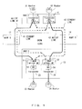
- FIG. 1 is a configuration of the optical network according to the first embodiment of the present invention.
- the optical network is an example of transmitting a signal at a communication speed of 40 Gbit/s.
- FIG. 1 is a configuration of an OADM (optical ad drop multiplex) ring network.
- WDM wavelength division multiplexing apparatus
- a wavelength division multiplexing apparatus (node A) 11 includes transponders (corresponding to optical transmission devices) 21 and 22.
- a wavelength division multiplexing apparatus 13 also includes two transponders 23 and 24.
- the network in FIG. 1 is an example in which the optical signals output from the transponders 21 and 22 are output respectively to an active line 41 and a standby line 44, passed through a wavelength division multiplexing apparatus 12 on a transmission line and received by the transponders 23 and 24, and the optical signals output from the transponders 21 and 22 are output respectively to a standby line 43 and an active line 42, passed through a wavelength division multiplexing apparatus 14 and received by the transponders 23 and 24.
- the transponders 21 and 22 convert the signals input respectively from the routers 31 and 32 into optical signals of the wavelengths for a WDM.
- the optical signal output from the transponder 21 is branched by an optical splitter 21a in two directions of the active line 41 and the standby line 43.
- the optical signal output from the transponder 22 is branched by an optical splitter 22a in two directions of the active line 42 and the standby line 44.
- the transponder 21 uses the path through the wavelength division multiplexing apparatus (node B) 12 to the transponder 23 of the wavelength division multiplexing apparatus (node C) 13 as the active line 41.
- the standby line 44 of the transponder 22 is accommodated in the physical line which also accommodates the active line 41 (refer to the standby line 44 indicated by the broken line in FIG. 1 ).
- the transponder 22 uses the path through the wavelength division multiplexing apparatus (node D) 14 to the wavelength division multiplexing apparatus 13 as the active line 42.
- the standby line 43 of the transponder 21 is accommodated in the physical line which also accommodates the active line 42.
- the transponders 23 and 24 of the wavelength division multiplexing apparatus 13 includes 1-wave optical switches (hereinafter referred to as optical switches) 51 and 52 for selecting one of the active line and the standby line and outputting an optical signal, and variable dispersion compensators (VDC) 53 and 54 for compensating for residual dispersion.
- the variable dispersion compensators 53 and 54 have the functions (corresponding to the acquisition device and the dispersion compensation device) of acquiring the dispersion compensation information (VDC setting value etc.) of another transponder and compensating for residual dispersion.
- the transponder 23 selects one of the active line 41 and the standby line 43 by the optical switch 51, compensates for the dispersion of the optical signal by the variable dispersion compensator 53, performs an optoelectronic conversion in the transponder 23, performs signal processing including error correction etc., performs an electro-optic conversion, and outputs the result to a router 33.
- the transponder 24 selects one of the active line 42 and the standby line 44 by the optical switch 52, performs signal-processing the optical signal dispersion-compensated by the variable dispersion compensator 54, and outputs the result to a router 34.
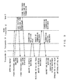
- FIG. 2 illustrates the sequence of the operation according to the first embodiment performed when trouble occurs in the active line 41 and the line is switched to the standby line 43.
- the variable dispersion compensator 53 of the transponder 23 normally sets the amount of dispersion compensation of the active line 41 dynamically to the optimum value.
- the transponder 23 inquires of the transponder 24 about the VDC setting value (corresponding to the dispersion compensation information) for the active line 42.
- the transponder 24 Upon receipt of the inquiry of the VDC setting value, the transponder 24 acquires the VDC setting value of its variable dispersion compensator 54, and transmits the VDC setting value to the transponder 23.
- the transponder 23 outputs the received VDC setting value to its variable dispersion compensator 53, and the variable dispersion compensator 53 sets the received VDC setting value as the VDC setting value (amount of dispersion compensation) of the standby line 43.
- the optical switch 51 switches a line to be used from the active line 41 to the standby line 43.
- the setting time of the VDC setting value for the standby line 43 can be reduced by setting the VDC setting value for the standby line 43 accommodated in the same optical line as the active line 42 of the transponder 24 on the basis of the VDC setting value of the active line 42.
- the line is switched after completing the setting of the VDC setting value for the variable dispersion compensator 53, but the VDC setting value can be changed after the optical switch 51 switches to a standby line.
- the VDC setting value of the transponder 24 which uses a part of the optical line as an active line can be acquired in advance, and the VDC setting value can be stored in memory.
- a dispersion compensator arranged for optical fiber and each node has a wavelength characteristic.
- the wavelength of the optical signal output from the transponder 21 is different from the wavelength of the optical signal output from the transponder 22, the amounts of residual dispersion in the receiving transponders 23 and 24 are also different.
- the VDC setting value for the active line 42 of the transponder 24 is set for the residual dispersion in the wavelength of the optical signal transmitted through the active line 42. Therefore, if the VDC setting value for the standby line 43 of the transponder 23 is set equal to the VDC setting value of he active line 42, then there is the possibility that the VDC setting value cannot be the optimum value due to different wavelengths of their optical signals when the VDC setting value for the standby line 43 of the transponder 23 is set equal to the VDC setting value of the active line 42.
- FIG. 3 illustrates the sequence of the operation according to the second embodiment to solve the problem above.
- the second embodiment is to consider the difference in wavelength of a signal, and corrects the VDC setting value by considering the difference in wavelength of a signal.
- the transponder 23 When the transponder 23 detects trouble with the active line 41, it inquires of the transmitting transponder 22 and the node D (wavelength division multiplexing apparatus 14) about the fiber type/fiber length, and DCM items.
- the data about the wavelength characteristic of a variable dispersion compensator can be obtained by designating the DCM items.
- the transponder 22 and the node D Upon receipt of the inquiry, the transponder 22 and the node D transmit their information about fiber type/fiber length and the DCM (dispersion compensator module) items.
- the transponder 23 inquires of the transponder 24 about a VDC setting value.
- the transponder 24 Upon receipt of the inquiry, the transponder 24 transmits the VDC setting value of its variable dispersion compensator 54 to the transponder 23.
- the transponder 23 inquires of the transponder 24 about a received wavelength.
- the transponder 24 inquires of the transmitting transponder 22 about a transmission wavelength.
- the transmitting transponder 22 transmits transmission wavelength data to the receiving transponder 24.
- the receiving transponder 24 transmits the wavelength data received from the transmitting transponder 24 as received wavelength data to the transponder 23.
- variable dispersion compensator 53 of the receiving transponder 23 corrects the VDC setting value to the wavelength on the basis of the VDC setting value received from the transponder 24 the received wavelength data. After the variable dispersion compensator 53 has switched from the active line 41 to the standby line 43, it further adjusts the VDC setting value.
- the correction of the VDC setting value can be performed by the following equation.
- VDC ⁇ ⁇ 1 VDC ⁇ ⁇ 2 + RD ⁇ ⁇ 2 - RD ⁇ ⁇ 1
- the residual dispersion RD ( ⁇ ) indicates the residual dispersion at the input terminal of the transponder for the wavelength ⁇ , and can be obtained by the following equation from a transmission line fiber dispersion Dfiber, and dispersion Ddcm of a dispersion compensator (dispersion-compensation fiber).
- RD ⁇ Dfiber ⁇ 1 ⁇ + Dfiber ⁇ 2 ⁇ ... + Dfibern + Ddcm ⁇ 1 ⁇ + Ddcm ⁇ 2 ⁇ ... + Ddcmn ⁇ Dfiber and Ddcm can be calculated from the following equation with respect to the wavelength ⁇ .
- Dfibern ⁇ a ⁇ 0 + a ⁇ 1 ⁇ ⁇ - ⁇ ref ⁇ FiberLengthn
- Ddcmn ⁇ b ⁇ 0 + b ⁇ 1 ⁇ ⁇ - ⁇ ref ⁇ DcfLengthn
- a0 and a1 respectively indicate the dispersion coefficient (ps/nm/km) and a dispersion slope (secondary dispersion) coefficient (ps/nm2/km) of a transmission line fiber.
- b0 and b1 respectively indicate the dispersion coefficient (ps/nm/km) and the dispersion slope (secondary dispersion) coefficient (ps/nm2/km) of the dispersion compensator (dispersion-compensation fiber).
- ⁇ ref indicates the regulated wavelength (for example, 1550nm) for regulation of the dispersion coefficient.
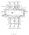
- FIG. 4 is a configuration of the network according to the third embodiment.
- the third embodiment is to obtain the VDC setting value of a standby line through which a signal of another wavelength in the same line is transmitted from the VDC setting values for a plurality of active lines through which signals of different wavelengths are transmitted.
- the same element as that also illustrated in FIG. 1 is assigned the same reference numeral, and the explanation is omitted here.
- a wavelength division multiplexing apparatus 15 illustrated in FIG. 4 includes three transponders 21, 22, and 25.
- the transponders 21, 22, and 25 convert the signals output from the routers 31, 32, and 35 into the signals of predetermined wavelength wavelengths ⁇ 1, ⁇ 2, and ⁇ 3 for VDMs. These optical signals are branched in two directions by the optical splitters 21a, 22a, and 25a.
- the signal of the wavelength ⁇ 1 branched by the optical splitter 21a is transmitted to the active line 41 and the standby line 43
- the signal of the wavelength ⁇ 2 branched by the optical splitter 22a is transmitted to the active line 42 and the standby line 44
- the signal of the wavelength ⁇ 3 branched by the optical splitter 25a is transmitted to the active line 45 and the standby line 46.
- a receiving wavelength division multiplexing apparatus 16 includes three transponders 23, 24, and 26.
- the transponder 26 includes an optical switch 55 for selecting one of the active line 45 and the standby line 46 and a variable dispersion compensator (VDC) 56 for compensating for the dispersion of an optical signal, and outputs a dispersion-compensated signal to a router 36.
- VDC variable dispersion compensator
- VDC setting value for the signal of the wavelength ⁇ 2 in the variable dispersion compensator 54 of the transponder 24 is VDC ( ⁇ 2)
- VDC setting value for the signal of the wavelength ⁇ 3 in the variable dispersion compensator 56 of the transponder 26 is VDC ( ⁇ 3)
- VDC setting value VDC ( ⁇ 1) for the wavelength ⁇ 1 can be obtained by the following equation.
- VDC ⁇ ⁇ 1 VDC ⁇ ⁇ 2 + VDC ⁇ ⁇ 2 - VDC ⁇ ⁇ 3 ⁇ ⁇ ⁇ 1 - ⁇ ⁇ 2 / ⁇ ⁇ 2 - ⁇ ⁇ 3
- the ratio of the difference between the VDC setting value VDC ( ⁇ 2) for the active line 42 through which the optical signal of the wavelength ⁇ 2 is transmitted and the VDC setting value VDC ( ⁇ 3) for the active line 45 through which the optical signal of the wavelength ⁇ 3 is transmitted to the difference between the wavelength ⁇ 2 and the wavelength ⁇ 3 is calculated, and the resultant value is multiplies by the different between the wavelength ⁇ 1 and the wavelength ⁇ 2, thereby calculating the VDC setting value for the standby line 43 through which the optical signal of the wavelength ⁇ 1.
- a VDC setting value can be obtained for the transmission line through which signals of different wavelengths are transmitted, and an appropriate VDC setting value can be calculated from the VDC setting values for the standby line through which optical signal having different wavelengths are transmitted.
- an error of the VDC setting value from a difference in wavelength of an optical signal can be reduced and the adjustment of the VDC setting value can be completed in a shorter time.
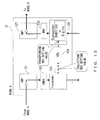
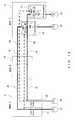
- FIG. 5 is a configuration of the wavelength division multiplexing apparatus 13 according to the fourth embodiment of the present invention.
- the standby line 43 in FIG. 5 is accommodated in the same optical line as the active line 42, and the standby line 44 is accommodated in the same optical line as the active line 41.
- the elements also illustrated in FIG. 1 are assigned the same reference numerals and the explanation is omitted here.
- a VDC setting circuit 61 of the transponder 23 acquires the VDC setting value (dispersion compensation information) from a VDC setting circuit 71 of the transponder 24, and the VDC setting value of the standby line 44 is determined on the basis of the VDC setting value.
- the VDC setting circuit 61 acquires the VDC setting value of the VDC setting circuit 71 of the transponder 24, and sets the acquired value as the VDC setting value of a variable dispersion compensation circuit 63 of the own device.
- a 1-wave optical switch 62 (corresponding to the optical switch 51 in FIG. 1 ) selects one of the active line (work path) 41 and the standby line (protection path) 44, and outputs the selected circuit to the variable dispersion compensation circuit (VDC) 63.
- the variable dispersion compensation circuit (corresponding to the VDC 53 in FIG. 1 ) 63 compensates for the dispersion of the optical signal on the basis of the VDC setting value output from the VDC setting circuit 61.
- An optoelectronic conversion circuit 64 converts an optical signal into an electric signal
- an error/trouble detection circuit 65 detects an error of an optical signal and the trouble of a line from the degradation of an error etc.
- a signal processing unit 66 converts the frame format of the received signal into the frame format of the signal of a client side.
- An electro-optic conversion circuit 67 outputs an electric signal into an optical signal and outputs the obtained signal.
- An optical switch state management unit 68 monitors the state of the 1-wave optical switch 62, and outputs the information about which the 1-wave optical switch 62 has selected, the active line 41 or the standby line 44.
- a VDC setting value calculation circuit 69 calculates the VDC setting value from the residual dispersion value determined by the physical condition of a transmission line, adjusts the VDC setting value for the best quality of the main signal on the basis of the data indicating the signal quality output from the error/trouble detection circuit 65, and outputs the adjusted value to the VDC setting circuit 61.
- the transponder 24 includes a VDC setting circuit 71, a 1-wave optical switch 72, a variable dispersion compensation circuit 73, an optoelectronic conversion circuit 74, an error/trouble detection circuit 75, a signal processing unit 76, an optical switch state management unit 78, and a VDC setting value calculation circuit 79.
- the functions of the circuit are the same as those of each circuit of the transponder 23.
- the VDC setting circuit 61 acquires the VDC setting value for the active line 42 from the VDC setting circuit 71 of the transponder 24, and outputs the acquired VDC setting value to the variable dispersion compensation circuit 63.
- the variable dispersion compensation circuit 63 dispersion-compensates the main signal on the basis of the VDC setting value.
- the VDC setting value calculation circuit 69 finely adjusts the data indicating the quality of the signal detected by the error/trouble detection circuit 65, for example, such that the frequency of the frame asynchronization of the main signal, the frequency of the asynchronization with reference to an error rate etc., and an error rate can be minimized, and the finely adjusted value is output to the VDC setting circuit 61.
- the VDC setting circuit 61 outputs the corrected VDC setting value to the variable dispersion compensation circuit 63 for dispersion-compensation.
- the VDC setting value for the active line 42 is acquired from the VDC setting circuit 71 of the transponder 24, and the VDC setting value of the standby line 44 accommodated in the same physical line as the active line 42 can be set on the basis of the acquired VDC setting value. Therefore, since the optimum VDC setting value can be acquired in a short time, the restoration time of trouble can be reduced when line trouble is detected and a switch is made to a standby line.
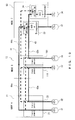
- FIG. 6 is a configuration of the wavelength division multiplexing apparatus 13 according to the fifth embodiment of the present invention.
- the VDC setting value stored in a VDC setting value storage circuit 82 of another transponder 24 is acquired by the VDC setting circuit 61, and the VDC setting value of the standby line 44 is set on the basis of the acquired value.
- the standby line 44 of the transponder 23 is accommodated in the same physical line (optical line) as the active line 42 of the transponder 24.
- the same circuit block as in FIG. 5 is assigned the same reference numeral, and the explanation is omitted here.
- a VDC setting value storage circuit 81 of the transponder 23 stores the VDC setting value calculated by the VDC setting value calculation circuit 69.
- the VDC setting value stored in the VDC setting value storage circuit 81 is output to the VDC setting circuit 61 of the own device, and output to the VDC setting circuit 71 of another transponder 24.
- the transponder 24 includes the VDC setting value storage circuit 82 for storing the VDC setting value calculated by the VDC setting value calculation circuit 79.
- the VDC setting value stored in the VDC setting value storage circuit 82 is output to the VDC setting circuit 71 and the VDC setting circuit 61 of another transponder 23.
- the VDC setting circuit 61 of the transponder 23 acquires the VDC setting value stored in the VDC setting value storage circuit 81 of the own device when the line is in the normal state, and outputs the acquired VDC setting value to the variable dispersion compensation circuit 63.
- the VDC setting circuit 61 acquires the VDC setting value stored in the VDC setting value storage circuit 82 of another transponder 24, and outputs the acquired VDC setting value to the variable dispersion compensation circuit 63.
- the VDC setting value calculation circuit 69 adjusts the VDC setting value such that the error rate etc. of the main signal detected by the error/trouble detection circuit 65 can be improved, and outputs the adjusted VDC setting value to the VDC setting value storage circuit 81.
- the VDC setting circuit 61 outputs to the variable dispersion compensation circuit 63 the VDC setting value newly written to the VDC setting value storage circuit 81.
- the variable dispersion compensation circuit 63 dispersion-compensates for the main signal on the basis of the VDC setting value.
- the error rate etc. of dispersion-compensated main signal is calculated by the error/trouble detection circuit 65, and the adjustment of the VDC setting value is further performed on the basis of the calculation result.
- the transponder 23 can acquire in advance (or when trouble occurs) the VDC setting value for the active line 42 accommodated in the same physical line as the standby line 44 from the VDC setting value storage circuit 82 of another transponder 24. Therefore, when the line trouble is detected, the optimum VDC setting value for compensation of the dispersion of the optical signal in the standby line 44 can be quickly output to the variable dispersion compensation circuit 63. Thus, the restoration time of the line trouble can be reduced.
- FIG. 7 is a configuration of the wavelength division multiplexing apparatus 13 according to the sixth embodiment of the present invention.
- the VDC setting value storage circuit 81 acquires the VDC setting value of the VDC setting value storage circuit 82 of another transponder 24, and outputs the acquired VDC setting value to the VDC setting circuit 61.
- the standby line 43 of the transponder 23 in FIG. 7 is accommodated in the same physical line as the active line 42 of the transponder 24.
- the same circuit block is assigned the ame reference numeral, and the explanation is omitted here.
- the VDC setting value storage circuit 81 of the transponder 23 in FIG. 7 stores the VDC setting value updated after the communication of signals of the active line 41.
- the VDC setting value storage circuit 82 of the transponder 24 stores the VDC setting value after the communication of the signal of the active line 42.
- the VDC setting value storage circuit 81 of the transponder 23 communicates with the VDC setting value storage circuit 82 of the transponder 24 directly or through another circuit when a normal operation is performed, acquires and stores the VDC setting value for the active line 42 stored in the VDC setting value storage circuit 82.
- the VDC setting circuit 61 reads the VDC setting value stored in the VDC setting value storage circuit 81, and outputs the VDC setting value to the variable dispersion compensation circuit 63.
- the variable dispersion compensation circuit 63 dispersion-compensates for the main signal on the basis of the VDC setting value.
- the VDC setting value storage circuit 81 of the transponder 23 acquires in advance (or when trouble occurs) the VDC setting value for the active line 42 stored in the VDC setting value storage circuit 82 of another transponder 24, and can set the VDC setting value of the standby line 44 on the basis of the acquired VDC setting value.
- the restoration time required when line trouble occurs can be reduced.
- the VDC setting value storage circuit 81 of the transponder 23 can communicate data directly (or through a communication interface) with the VDC setting value storage circuit 82 of another transponder 24, an appropriate VDC setting value for the standby line 44 can be acquired before trouble occurs.
- the restoration time for the trouble can be further reduced.
- the VDC setting circuit 61, the VDC setting value storage circuit 81, etc. are not VDC setting values themselves, but the information (dispersion compensation information) for calculation of the VDC setting value can be acquired or stored.
- FIG. 8 is a configuration of a network according to the seventh embodiment of the present invention.
- the seventh embodiment is to transfer the information for dispersion-compensation using another line other than the line for transmission of a main signal (OSC (optical supervisor channel) used in transmitting monitoring information).
- OSC optical supervisor channel
- the wavelength division multiplexing apparatus can be provided with a function called a control plane for easy maintenance and management of the entire network.
- the control plane function controls and monitors a transponder using a controlling and monitoring channel independent of the main signal called an OSC.
- OSC main signal
- the VDC setting value of a transponder, the direction of an optical switch, the wavelength of an optical signal, a fiber type, a fiber length (span length) (these pieces of information are collectively called dispersion information) and a node ID (ID of a wavelength division multiplexing apparatus) are transmitted to all wavelength division multiplexing apparatuses in the network.
- Each of the wavelength division multiplexing apparatuses 11 through 14 includes OSC units 91 through 94.
- the OSC units 91 through 94 transmit dispersion information configured by all or a part of a VDC setting value of a transponder, the direction of an optical switch, wavelength information, a fiber type, a fiber length (distance of a transmission line), etc. together with a node ID to an OSC. Simultaneously, the dispersion information transferred from another apparatus is acquired, and the acquired dispersion information is stored in the storage device etc. of the transponder. Otherwise, the optimum VDC setting value for the standby line of the own device is calculated in advance from the dispersion information about another transponder, and stored in a storage circuit.
- the VDC setting value (or information for calculation of a VDC setting value) etc. of each transponder can be transmitted to all apparatuses using the OSC, a transponder which has detected line trouble can set the optimum VDC setting value for the standby line of the own device according to the dispersion information acquired through the OSC in a short time.
- each transponder can also calculate in advance the VDC setting value for the standby line from the dispersion information acquired through the OSC, the restoration time for a switch from the active line to the standby line can be reduced.
- FIG. 9 is an example of a configuration of the wavelength division multiplexing apparatus according to the seventh embodiment described above.
- the wavelength division multiplexing apparatus in FIG. 9 corresponds to the wavelength division multiplexing apparatus 12 of the node B in the transmission line illustrated in FIG. 1.
- FIG. 1 is an example of a case in which the main signal passes through the node B, but FIG. 9 illustrates a case in which the main signal transmitted from the node A is received by a transponder 103 of the node B and output to a router or a line not illustrated in the attached drawings, and the main signal received by another transponder 106 is output to the node C (wavelength division multiplexing apparatus 13).
- the wavelength division multiplexing apparatus 12 includes an optical amplifier 101 for amplifying an optical signal from the wavelength division multiplexing apparatus 11 (node A), a demultiplexer 102 for demultiplexing an amplified optical signal, a transponder 103 for compensating for the dispersion of the optical signal, a CPU 104 for collecting the VDC setting value of the transponder 103, and an OSC unit 105 for converting dispersion information such as a VDC setting value etc. output from the CPU 104 into a predetermined data format and transmitting the information to the OSC.
- an optical amplifier 101 for amplifying an optical signal from the wavelength division multiplexing apparatus 11 (node A)
- a demultiplexer 102 for demultiplexing an amplified optical signal
- a transponder 103 for compensating for the dispersion of the optical signal
- a CPU 104 for collecting the VDC setting value of the transponder 103
- an OSC unit 105 for converting dispersion information such as a VDC
- the wavelength division multiplexing apparatus 12 further includes a transponder 106 for receiving an optical signal input from a router or other lines not illustrated in the attached drawings and compensating for dispersion, a multiplexer 107 for multiplexing an output signal of the transponder 106, and an optical amplifier 108 for amplifying the output of the multiplexer 107.
- the transponders 103 and 106 have a configuration illustrated in, for example, FIG. 5 , 6 , or 7 .
- the operation of the process by the CPU 104 is described below with reference to the flowchart in FIG. 10 .
- the transponder 103 notifies the CPU 104 of the VDC setting value (S11 in FIG. 10 ).
- the CPU 104 outputs the received VDC setting value to the OSC unit 105 (S12).
- the OSC unit 105 sets the VDC setting value in a blank byte of a predetermined signal format (for example, OC-3 of SONET) (S13).
- the OSC unit 105 performs an electro-optic conversion on the data of a predetermined signal format, and transmits the converted optical signal to a wavelength division multiplexing apparatus in the downstream (S14).
- the OSC unit 93 acquires dispersion information such as a VDC setting value, a signal wavelength, a fiber length, etc. transferred from the OSC units 91 through 94, and can obtain a corresponding path according to the acquired dispersion information, for example, the VDC setting value for the active line 42 for couple of the transponder 22 to the transponder 24. Then, using the VDC setting value of the active line 42, an appropriate VDC setting value for the standby line can be set using the VDC setting value of the active line 42. Thus, when line trouble occurs and is to be switched to a standby line, the time required to set the VDC setting value of the standby line as the optimum value can be reduced.
- FIG. 11 is a flowchart of the operation of the process performed when the transponder 103 notifies the OSC unit 105 of the VDC setting value.
- the transponder 103 notifies the OSC unit 105 of the VDC setting value (S21 in FIG. 11 ).
- the OSC unit 105 sets the VDC setting value in the blank byte of data of a predetermined signal format (for example, OC-3 of SONET) (S22).
- a predetermined signal format for example, OC-3 of SONET
- the OSC unit 105 performs an electro-optic conversion the data of a predetermined signal format, and transmits the VDC setting value (or other information) to a node in a downstream using an OSC (S23).
- OSC OSC
- each transponder can transmit the dispersion information about the own device to another transponder using the OSC. Then, each transponder can store the received dispersion information in the storage circuit of the own device, calculate and store in advance the VDC setting value for the standby line of the own device.
- a variable dispersion compensator can determine the optimum dispersion compensation value for the standby line in a short time, thereby reducing the restoration time of line trouble.
- FIG. 12 is a configuration of the network according to the eighth embodiment.
- the eighth embodiment is to allow each transponder to transmit dispersion information through digital wrapper, SONET (synchronous optical network), DCC (data communication channel), etc.
- SONET synchronous optical network
- DCC data communication channel
- the wavelength division multiplexing apparatus can use the technology called digital wrapper capable of performing a long-distant transmission.
- the digital wrapper indicates a frame format in which data is enclosed by a channel header and the data of forward error correction FEC.
- the eighth embodiment is to transmit dispersion information using the digital wrapper or a blank byte of the overhead of DCC.
- the wavelength division multiplexing apparatus 12 includes transponders 111 and 112.
- the digital wrapper is generated and terminated in each transponder.
- the transponder 111 inserts the dispersion information configured by all or a part of the VDC setting value for a path a1 of the active line 41 with the transponder 21, the direction of an optical switch, wavelength information, a fiber type, and a fiber length, and a node ID into a blank byte of the overhead of the digital wrapper, and transmits them to another transponder.
- the transponder 23 inserts the dispersion information configured by all or a part of the VDC setting value for a path b1 of the active line 41 with the transponder 112, the direction of an optical switch, wavelength information, a fiber type, and a fiber length, and a node ID into a blank byte of the overhead of the digital wrapper, and transmits them to another transponder.
- the transponder 24 can calculate the VDC setting value for the path c1 of the standby line 44 accommodated in the same physical line on the basis of the VDC setting value of the path a1 transmitted from the transponder 111 and the VDC setting value of the path b1 transmitted from the transponder 23.
- each transponder can acquire the VDC setting value of the transponder in the upstream (transmitting side) of the own device by transmitting the VDC setting value of each transponder to a network using the digital wrapper. Therefore, before line trouble occurs or after it has occurred, an appropriate VDC setting value can be set for the standby line in the variable dispersion compensator. Thus, the restoration time of the line trouble can be reduced.
- FIG. 13 is an example of a configuration of the wavelength division multiplexing apparatus 12 according to the eighth embodiment above.
- the wavelength division multiplexing apparatus in FIG. 13 corresponds to the wavelength division multiplexing apparatus 12 (node B) in the transmission line in FIG. 1.
- FIG. 1 is an example of the case in which a main signal passes through the node B.
- FIG. 13 illustrates the case in which a main signal transmitted from the node A is received by a transponder 123 of the node B, and a main signal input to a transponder 125 from a router or another line not illustrated in the attached drawings is output to the node C (wavelength division multiplexing apparatus 13).
- the wavelength division multiplexing apparatus 12 includes an optical amplifier 121 for amplifying an optical signal from the wavelength division multiplexing apparatus 11 (node A), a demultiplexer 122 for demultiplexing the amplified optical signal, the transponder 123 for performing dispersion-compensation, an optoelectronic conversion, etc., a CPU 124 for collecting the VDC setting value of the transponder 123 and outputting it to the transponder 125, the transponder 125, a multiplexer 126 for multiplexing the optical signal, and an optical amplifier 127 for amplifying the output light of the multiplexer 126 and transmitting the light to the transmission line coupled to the node C (wavelength division multiplexing apparatus 13).
- the transponders 123 and 125 have a configuration illustrated in, for example, FIG. 5 , 6 , or 7 .
- the VDC setting value is output to the transponder 125.
- the transponder 125 inserts the VDC setting value etc. into a blank byte of a known signal format such as SONET DCC etc. and transmits it to the transmission line.
- the VDC setting value etc. of each transponder is transmitted using a blank byte of a known signal format, received and stored by each transponder, thereby setting an appropriate VDC setting value for a standby line in the variable dispersion compensator.
- the restoration time of line trouble can be reduced.
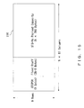
- FIG. 14 illustrates a frame format of the digital wrapper regulated in the ITU-T, G709.
- the frame format of the digital wrapper has a configuration of wrapping data with an overhead and an error correction code FEC (forward error correction).
- FEC forward error correction
- the VDC setting value of each transponder, wavelength information, etc. are inserted into a RES (reserved for future international standardization) 132 not currently used in an ODUk (optical channel data unit) OH (overhead) 131 in FIG. 14 , and transmitted.
- the dispersion information is transmitted using the OSC in the seventh embodiment, for example, it is transmitted through a controlling channel by inserting the VDC setting value of a transponder, wavelength information about a signal, etc. into the payload of the SONET frame illustrated in FIG. 5 .
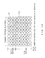
- dispersion information is transmitted using the SONET DCC, it is transmitted by inserting the VDC setting value, wavelength information about a signal, etc. into an undefined byte 151a of the transport overhead 151 marked with ⁇ in FIG. 16 .
- the information to be transmitted by each transponder in a predetermined signal format is not limited to the VDC setting value itself, but can be information for calculation of the VDC setting value on the reception side.
- FIGS. 17 through 19 illustrate other network formats than ring networks. In the explanation below, the same elements in FIG. 1 and others are assigned the same reference numerals, and the detailed description is omitted here.
- FIG. 17 is an example of a network of a mesh configuration.
- the optimum dispersion compensation value of the standby line can also be set for the network with the mesh configuration in the same method as in the above-mentioned embodiment.
- the network with the mesh configuration in FIG. 17 has the wavelength division multiplexing apparatus 15 (node E) in addition to each node in FIG. 1 , and the wavelength division multiplexing apparatus 15 has the transponders 113 and 114.
- a standby line 47 of the transponder 22 passes through the wavelength division multiplexing apparatuses 12 and 15, and input to the transponder 24 of the wavelength division multiplexing apparatus 13.
- the path a1 of the active line 41 of the transponder 21 is input to the transponder 111 of the wavelength division multiplexing apparatus 12, and the path b1 of the active line 48 of the transponder 112 is input to the transponder 113 of the wavelength division multiplexing apparatus 15.
- the path c1 of an active line 49 of the wavelength division multiplexing apparatus 15 (node E) is input to the transponder 23 of the wavelength division multiplexing apparatus 13.
- the wavelength division multiplexing apparatus 12 inserts the VDC setting value (or dispersion compensation value) for the path a1 of the transponder 111 into the blank byte of a predetermined data format, and transmits the value to each wavelength division multiplexing apparatus.
- the wavelength division multiplexing apparatus 15 inserts the VDC setting value for the path b1 of the transponder 113 into the blank byte of the predetermined data format, and transmits it to the network.
- the transponder 23 inserts the VDC setting value for the path c1 directly into the transponder 24 or into the blank byte of the predetermined data format and outputs it.
- the transponder 24 obtains the VDC setting value of the path d1 of the standby line 47 by adding the VDC setting value of the path a1, the VDC setting value of the path b1, and the VDC setting value of the path c1.
- the transponder 24 can calculate a preferred VDC setting value of the standby line 47 in advance by acquiring the dispersion compensation value of the paths a1, b1, and c1 respectively from the transponders 12, 15, and 23.
- the restoration time after the switch to the standby line 47 until the communication of signals can be reduced.
- FIG. 18 is an example of a network with the linear configuration.
- a preferred VDC setting value of the standby line 44 accommodated in the same optical line can be calculated from the VDC setting value for the active line 41 of the transponder 23 when the active line 41 and the standby line 44 are accommodated in the same physical line.
- the transponder 24 acquires a VDC setting value for the active line 41 from the transponder 23, and the VDC setting value for the standby line 44 can be set on the basis of the acquired value.
- FIG. 19 is another example of a network with the linear configuration.
- the wavelength division multiplexing apparatus 12 has the transponder 111 and the transponder 112, an active line 42a and its standby line 44a are input to the wavelength division multiplexing apparatus 11, an active line 42b of the transponder 112 is input to the transponder 24.
- the active line 41 and its standby line 43 passes through the wavelength division multiplexing apparatus 12 from the transponder 21, and is input to the transponder 23.
- the transponder 23 can estimate the VDC setting value of the standby line 43 by acquiring the VDC setting value for the active line 42a of the wavelength division multiplexing apparatus 11 and the VDC setting value for the active line 42b of the transponder 24.
- the transponder 23 can calculate in advance a preferred VDC setting value of the standby line 43 by acquiring the VDC setting value (or the value indicating residual dispersion) for the active line 42a of the transponder 111 and the VDC setting value for the active line 42b of the transponder 24.
- a signal can be communicated in a short time by switching to the standby line 43, thereby reducing the restoration time of the trouble.
- the method for each transponder acquiring a VDC setting value etc. in the network with the mesh configuration or the linear configuration can be any of the above-mentioned first through eighth embodiments.
- the present invention is not limited to the above-mentioned embodiment, but can be configured as follows.
Landscapes
- Engineering & Computer Science (AREA)
- Computer Networks & Wireless Communication (AREA)
- Signal Processing (AREA)
- Optical Communication System (AREA)
Abstract
When line trouble occurs in an optical network, the restoration time can be reduced. A transponder 21 includes an active line 41 and a standby line 43, and a transponder 22 includes an active line 42 and a standby line 44. The standby line 44 of the transponder 22 is accommodated in the same optical line as the active line 41 of the transponder 21. Upon detection of line trouble, the receiving transponder 24 acquires a VDC setting value for the active line 41, and sets the VDC setting value for the standby line 44 on the basis of the acquired VDC setting value.
Description
- The present invention relates to a wavelength division multiplexing apparatus and a dispersion compensating method for an optical signal.
- Recently, a desire to implement a 40 Gbit/s optical system of the next generation grows for its merits in larger capacity, smaller structure, lower cost, higher frequency utilization, etc.
Generally, since various optical parts configuring a device arranged for optical fiber and each node have wavelength dispersion, the distortion of an optical waveform occurs due to the wavelength dispersion during the passage of modulated signal light through them. Since the distortion of an optical waveform incurs the degradation of transmission quality (error rate etc.), it can be a factor of limiting the system performance relating to a maximum transmission distance etc. - Generally, a dispersion tolerance is used as an index indicating the tolerance to waveform distortion by the dispersion of a transmitter-receiver. For example, the dispersion tolerance of a transmitter-receiver at the bit rate of 40 Gbit/s or more is about several tens ps/nm. It is very low as compared with the dispersion tolerance of about 1000 ps/nm of the 10 Gbit/s signal which is currently used popularly. Therefore, to realize the transmission of signals of a bit rate of 40 Gbit/s or more, it is necessary to perform dispersion control at high accuracy by, for example, arranging a variable dispersion compensator (VDC) at an input terminal of a receiver.
- On the other hand, at present, to reserve high reliability of a network, it is required to perform high-speed (normally 50 ms or less) service recovery if trouble occurs when, for example, optical fiber is discoupled etc.
To attain the above-mentioned objects, a protection system represented by an OUPSR (optical unidirectional path switched ring) has been introduced. -
FIG. 20 is an example of a configuration of an optical network in the OUPSR system. In the optical network, a wavelengthdivision multiplexing apparatus 201, an OADM (optical add drop multiplexer) 202, a wavelengthdivision multiplexing apparatus 203, and anOADM 204 are coupled in ring-shaped form. - A signal input from a
router 211 is output to anactive line 221 through atransponder 212 and anoptical splitter 213, and input to the wavelengthdivision multiplexing apparatus 203 on the receiving side through theOADM 202. The wavelengthdivision multiplexing apparatus 203 has a 1-wave optical switch 214 and atransponder 215, and outputs an optical signal dispersion-compensated by thetransponder 215 to arouter 216. Thetransponder 212 has astandby line 222 through another OADM 204. - In the optical network system, when trouble occurs in the
active line 221, the receivingtransponder 215 switches to thestandby line 222 to receive a signal.
For example, since the dispersion tolerance is low in the communication at 40 Gbit/s, the receivingtransponder 215 has to make an adjustment for setting the optimum value of the amount of dispersion compensation of the variable dispersion compensator, and several minutes are required from the occurrence of the trouble to the communication of signals. - In the
patent document 1, the optimum amounts of dispersion compensation of a plurality of optical transmission routes are stored in memory in advance, and the amount of dispersion compensation of a variable dispersion compensator is controlled depending on the optimum amount of dispersion compensation of a changed route stored in the memory when a change of the optical transmission route is detected by the route change detection device. - Patent Document 1: Japanese Laid-open Patent Publication No.
2003-179580 - The present invention aims at reducing the restoration time for line trouble in an optical network.
An aspect of the wavelength division multiplexing apparatus is a wavelength division multiplexing apparatus used in a network in which a transmitting optical transmission device and a receiving optical transmission device are coupled via an active line and a standby line, and includes an acquisition device for acquiring dispersion compensation information for the active line accommodated in a same optical line as the standby line from another optical transmission device, and a dispersion compensation device for compensating for dispersion of an optical signal transmitted through the standby line according to the dispersion compensation information acquired by the acquisition device. - The wavelength division multiplexing apparatus can reduce the restoration time for line trouble.
In the wavelength division multiplexing apparatus, the acquisition device acquires dispersion compensation information stored in a storage device of the other optical transmission device before detecting trouble. - With the above-mentioned configuration, since the dispersion compensation information can be acquired for the active line of the other optical transmission device before the occurrence of the trouble, the restoration time for the trouble can be further reduced.
In the above-mentioned wavelength division multiplexing apparatus, the acquisition device receives the dispersion compensation information transmitted from the other optical transmission device to the network, and the dispersion compensation device dispersion-compensates for the standby line according to the dispersion compensation information received by the acquisition device. - With the above-mentioned configuration, the dispersion compensation information about the other optical transmission device transmitted on the network can be received and the dispersion-compensation of the standby line can be performed.
In the wavelength division multiplexing apparatus above, the acquisition device corrects the dispersion compensation information received from the other optical transmission device depending on the difference between the wavelength of the optical signal received by the other optical transmission device and wavelength of the optical signal received by the own device, and performs a calculation using the corrected value as the dispersion compensation information for the standby line. - With the above-mentioned configuration, appropriate dispersion compensation information depending on the wavelength can be acquired from the dispersion compensation information for the optical signals having different wavelengths.
The wavelength division multiplexing apparatus further includes an output device for transmitting the dispersion compensation information about the dispersion compensation device to the other optical transmission device on the network using an OSC (optical supervisor channel). - With the above-mentioned configuration, the dispersion compensation information about the own device can be transmitted to the other optical transmission device using the OSC.
The wavelength division multiplexing apparatus above also includes an output device for inserting the dispersion compensation information about the dispersion compensation device into the blank byte of the overhead of the signal format of the main signal and transmitting the information to the other optical transmission device in the network. - With the above-mentioned configuration, the dispersion compensation information about the own device can be transmitted using the signal format of the main signal.
The wavelength division multiplexing apparatus above further includes a storage device for storing dispersion compensation information in the dispersion compensation device and outputting the stored dispersion compensation information to the other optical transmission device, and the acquisition device acquires the dispersion compensation information for the active line accumulated in the same optical line as the standby line of the own device from the storage device of the other optical transmission device. - With the above-mentioned configuration, the dispersion compensation information for the active line is acquired from the storage device of the other optical transmission device to set the dispersion compensation information about the own device.
In the wavelength division multiplexing apparatus, the acquisition device includes a setting device for setting a dispersion compensation value of the dispersion compensation device, and outputting the set dispersion compensation value to the other optical transmission device, and the setting device acquires a dispersion compensation value for the active line accumulated in the same optical line as the standby line of the own device from the setting device of the other optical transmission device, and sets the acquired dispersion compensation value in the dispersion compensation device. - With the configuration, a dispersion compensation value for the active line can be acquired from the setting device of the other optical transmission device, and an appropriate dispersion compensation value for the dispersion compensation device of the own device can be set in a short time on the basis of the acquired value.
- The wavelength division multiplexing apparatus includes a signal quality detection device for detecting the signal quality of a main signal to be received, a calculation device for calculating the dispersion compensation information corrected on the basis of the signal quality detected by the signal quality detection device, and a storage device for storing the dispersion compensation information calculated by the calculation device and outputting the stored dispersion compensation information to the other optical transmission device. The acquisition device includes a setting device for acquiring the dispersion compensation information for the active line accumulated in the same optical line as the standby line of the own device from the storage device of the other optical transmission device, and setting a dispersion compensation value of the dispersion compensation device according to the acquired dispersion compensation information.
- With the configuration, the setting device can acquire the dispersion compensation information for the active line from the storage device of the other optical transmission device, and set an appropriate dispersion compensation value in the dispersion compensation device of the own device in a short time on the basis of the acquired value.
-
-
FIG. 1 is a configuration of the network according to the first embodiment of the present invention; -
FIG. 2 illustrates the sequence of the operation according to the first embodiment of the present invention; -
FIG. 3 illustrates the sequence of the operation according to the second embodiment of the present invention; -
FIG. 4 is a configuration of the network according to the third embodiment of the present invention; -
FIG. 5 is a configuration of the wavelength division multiplexing apparatus according to the fourth embodiment of the present invention; -
FIG. 6 is a configuration of the wavelength division multiplexing apparatus according to the fifth embodiment of the present invention; -
FIG. 7 is a configuration of the wavelength division multiplexing apparatus according to the sixth embodiment of the present invention; -
FIG. 8 is a configuration of the network according to the seventh embodiment of the present invention; -
FIG. 9 is an example of a configuration of the wavelength division multiplexing apparatus according to the seventh embodiment of the present invention; -
FIG. 10 is a flowchart of the operation of the process according to the seventh embodiment of the present invention; -
FIG. 11 is a flowchart of the operation of another process according to the seventh embodiment of the present invention; -
FIG. 12 is a configuration of the network according to the eighth embodiment of the present invention; -
FIG. 13 is an example of a configuration of the wavelength division multiplexing apparatus according to the eighth embodiment of the present invention; -
FIG. 14 is an example of the data format of Digital Wrapper; -
FIG. 15 is a configuration of the SONET frame; -
FIG. 16 is a configuration of the overhead of the SONET frame; -
FIG. 17 illustrates a network of a mesh configuration; -
FIG. 18 illustrates a network of a linear configuration; -
FIG. 19 illustrates another network of a linear configuration; and -
FIG. 20 is a configuration of a conventional network. - The preferred embodiments of the present invention are described below with reference to the attached drawings.
FIG. 1 is a configuration of the optical network according to the first embodiment of the present invention. The optical network is an example of transmitting a signal at a communication speed of 40 Gbit/s. -
FIG. 1 is a configuration of an OADM (optical ad drop multiplex) ring network.
For simple explanation, it is assumed that the wavelength division multiplexing apparatus (WDM) includes two transponders. A wavelength division multiplexing apparatus (node A) 11 includes transponders (corresponding to optical transmission devices) 21 and 22. A wavelengthdivision multiplexing apparatus 13 also includes twotransponders - The network in
FIG. 1 is an example in which the optical signals output from thetransponders active line 41 and astandby line 44, passed through a wavelengthdivision multiplexing apparatus 12 on a transmission line and received by thetransponders transponders standby line 43 and anactive line 42, passed through a wavelengthdivision multiplexing apparatus 14 and received by thetransponders - The
transponders routers transponder 21 is branched by anoptical splitter 21a in two directions of theactive line 41 and thestandby line 43. The optical signal output from thetransponder 22 is branched by anoptical splitter 22a in two directions of theactive line 42 and thestandby line 44. - The
transponder 21 uses the path through the wavelength division multiplexing apparatus (node B) 12 to thetransponder 23 of the wavelength division multiplexing apparatus (node C) 13 as theactive line 41. Thestandby line 44 of thetransponder 22 is accommodated in the physical line which also accommodates the active line 41 (refer to thestandby line 44 indicated by the broken line inFIG. 1 ). - The
transponder 22 uses the path through the wavelength division multiplexing apparatus (node D) 14 to the wavelengthdivision multiplexing apparatus 13 as theactive line 42. Thestandby line 43 of thetransponder 21 is accommodated in the physical line which also accommodates theactive line 42. - The
transponders division multiplexing apparatus 13 includes 1-wave optical switches (hereinafter referred to as optical switches) 51 and 52 for selecting one of the active line and the standby line and outputting an optical signal, and variable dispersion compensators (VDC) 53 and 54 for compensating for residual dispersion. Thevariable dispersion compensators - The
transponder 23 selects one of theactive line 41 and thestandby line 43 by theoptical switch 51, compensates for the dispersion of the optical signal by thevariable dispersion compensator 53, performs an optoelectronic conversion in thetransponder 23, performs signal processing including error correction etc., performs an electro-optic conversion, and outputs the result to arouter 33. Similarly, thetransponder 24 selects one of theactive line 42 and thestandby line 44 by theoptical switch 52, performs signal-processing the optical signal dispersion-compensated by thevariable dispersion compensator 54, and outputs the result to arouter 34. -
FIG. 2 illustrates the sequence of the operation according to the first embodiment performed when trouble occurs in theactive line 41 and the line is switched to thestandby line 43.
Thevariable dispersion compensator 53 of thetransponder 23 normally sets the amount of dispersion compensation of theactive line 41 dynamically to the optimum value. - When it is determined that line trouble has occurred in the
active line 41 due to the disconnection of an optical signal, frame asynchronization, the degradation of an error rate, etc., thetransponder 23 inquires of thetransponder 24 about the VDC setting value (corresponding to the dispersion compensation information) for theactive line 42. - Upon receipt of the inquiry of the VDC setting value, the
transponder 24 acquires the VDC setting value of itsvariable dispersion compensator 54, and transmits the VDC setting value to thetransponder 23.
Thetransponder 23 outputs the received VDC setting value to itsvariable dispersion compensator 53, and thevariable dispersion compensator 53 sets the received VDC setting value as the VDC setting value (amount of dispersion compensation) of thestandby line 43. when the change of the VDC setting value is completed, theoptical switch 51 switches a line to be used from theactive line 41 to thestandby line 43. - The setting time of the VDC setting value for the
standby line 43 can be reduced by setting the VDC setting value for thestandby line 43 accommodated in the same optical line as theactive line 42 of thetransponder 24 on the basis of the VDC setting value of theactive line 42. - In the example above, the line is switched after completing the setting of the VDC setting value for the
variable dispersion compensator 53, but the VDC setting value can be changed after theoptical switch 51 switches to a standby line. In addition, the VDC setting value of thetransponder 24 which uses a part of the optical line as an active line can be acquired in advance, and the VDC setting value can be stored in memory. - According to the first embodiment above, when line trouble occurs and a switch is made to a standby line, the time required to communicate a signal can be reduced.
Generally, a dispersion compensator arranged for optical fiber and each node has a wavelength characteristic. When the wavelength of the optical signal output from thetransponder 21 is different from the wavelength of the optical signal output from thetransponder 22, the amounts of residual dispersion in the receivingtransponders - The VDC setting value for the
active line 42 of thetransponder 24 is set for the residual dispersion in the wavelength of the optical signal transmitted through theactive line 42. Therefore, if the VDC setting value for thestandby line 43 of thetransponder 23 is set equal to the VDC setting value of heactive line 42, then there is the possibility that the VDC setting value cannot be the optimum value due to different wavelengths of their optical signals when the VDC setting value for thestandby line 43 of thetransponder 23 is set equal to the VDC setting value of theactive line 42. -
FIG. 3 illustrates the sequence of the operation according to the second embodiment to solve the problem above. The second embodiment is to consider the difference in wavelength of a signal, and corrects the VDC setting value by considering the difference in wavelength of a signal. - When the
transponder 23 detects trouble with theactive line 41, it inquires of the transmittingtransponder 22 and the node D (wavelength division multiplexing apparatus 14) about the fiber type/fiber length, and DCM items. The data about the wavelength characteristic of a variable dispersion compensator can be obtained by designating the DCM items. - Upon receipt of the inquiry, the
transponder 22 and the node D transmit their information about fiber type/fiber length and the DCM (dispersion compensator module) items.
Next, thetransponder 23 inquires of thetransponder 24 about a VDC setting value. Upon receipt of the inquiry, thetransponder 24 transmits the VDC setting value of itsvariable dispersion compensator 54 to thetransponder 23. - Next, the
transponder 23 inquires of thetransponder 24 about a received wavelength. Thetransponder 24 inquires of the transmittingtransponder 22 about a transmission wavelength. Upon receipt of the inquiry, the transmittingtransponder 22 transmits transmission wavelength data to the receivingtransponder 24. The receivingtransponder 24 transmits the wavelength data received from the transmittingtransponder 24 as received wavelength data to thetransponder 23. - The
variable dispersion compensator 53 of the receivingtransponder 23 corrects the VDC setting value to the wavelength on the basis of the VDC setting value received from thetransponder 24 the received wavelength data. After thevariable dispersion compensator 53 has switched from theactive line 41 to thestandby line 43, it further adjusts the VDC setting value. - Described below is the method of correcting the residual dispersion on the basis of the fiber type/fiber length and the wavelength characteristic of the variable dispersion compensator of the node on the reception path.
When the wavelength of the output light of the transmittingtransponder 21 is λ1, the wavelength of the output light of thetransponder 22 is λ2, and the residual dispersion at the input terminal of the transponder for the wavelength λ is RD, the correction of the VDC setting value can be performed by the following equation. -

-

-

where a0 and a1 respectively indicate the dispersion coefficient (ps/nm/km) and a dispersion slope (secondary dispersion) coefficient (ps/nm2/km) of a transmission line fiber. - In the equation above, b0 and b1 respectively indicate the dispersion coefficient (ps/nm/km) and the dispersion slope (secondary dispersion) coefficient (ps/nm2/km) of the dispersion compensator (dispersion-compensation fiber). In the equation above, λref indicates the regulated wavelength (for example, 1550nm) for regulation of the dispersion coefficient.
- By the equation above, the VDC setting value of the standby line for the optical signal of the wavelength λ1 can be obtained.
Next,FIG. 4 is a configuration of the network according to the third embodiment. The third embodiment is to obtain the VDC setting value of a standby line through which a signal of another wavelength in the same line is transmitted from the VDC setting values for a plurality of active lines through which signals of different wavelengths are transmitted. The same element as that also illustrated inFIG. 1 is assigned the same reference numeral, and the explanation is omitted here. - A wavelength
division multiplexing apparatus 15 illustrated inFIG. 4 includes threetransponders transponders routers optical splitters optical splitter 21a is transmitted to theactive line 41 and thestandby line 43, the signal of the wavelength λ2 branched by theoptical splitter 22a is transmitted to theactive line 42 and thestandby line 44, and the signal of the wavelength λ3 branched by theoptical splitter 25a is transmitted to theactive line 45 and thestandby line 46. - A receiving wavelength
division multiplexing apparatus 16 includes threetransponders transponder 26 includes anoptical switch 55 for selecting one of theactive line 45 and thestandby line 46 and a variable dispersion compensator (VDC) 56 for compensating for the dispersion of an optical signal, and outputs a dispersion-compensated signal to arouter 36. - If the VDC setting value for the signal of the wavelength λ2 in the
variable dispersion compensator 54 of thetransponder 24 is VDC (λ2), and the VDC setting value for the signal of the wavelength λ3 in thevariable dispersion compensator 56 of thetransponder 26 is VDC (λ3), then the VDC setting value VDC (λ1) for the wavelength λ1 can be obtained by the following equation.
- The ratio of the difference between the VDC setting value VDC (λ2) for the
active line 42 through which the optical signal of the wavelength λ2 is transmitted and the VDC setting value VDC (λ3) for theactive line 45 through which the optical signal of the wavelength λ3 is transmitted to the difference between the wavelength λ2 and the wavelength λ3 is calculated, and the resultant value is multiplies by the different between the wavelength λ1 and the wavelength λ2, thereby calculating the VDC setting value for thestandby line 43 through which the optical signal of the wavelength λ1. - According to the above-mentioned third embodiment, a VDC setting value can be obtained for the transmission line through which signals of different wavelengths are transmitted, and an appropriate VDC setting value can be calculated from the VDC setting values for the standby line through which optical signal having different wavelengths are transmitted. Thus, an error of the VDC setting value from a difference in wavelength of an optical signal can be reduced and the adjustment of the VDC setting value can be completed in a shorter time.
- Next,
FIG. 5 is a configuration of the wavelengthdivision multiplexing apparatus 13 according to the fourth embodiment of the present invention. Thestandby line 43 inFIG. 5 is accommodated in the same optical line as theactive line 42, and thestandby line 44 is accommodated in the same optical line as theactive line 41. In the description below, the elements also illustrated inFIG. 1 are assigned the same reference numerals and the explanation is omitted here. - In the fourth embodiment, a
VDC setting circuit 61 of thetransponder 23 acquires the VDC setting value (dispersion compensation information) from aVDC setting circuit 71 of thetransponder 24, and the VDC setting value of thestandby line 44 is determined on the basis of the VDC setting value. - The
VDC setting circuit 61 acquires the VDC setting value of theVDC setting circuit 71 of thetransponder 24, and sets the acquired value as the VDC setting value of a variabledispersion compensation circuit 63 of the own device.
A 1-wave optical switch 62 (corresponding to theoptical switch 51 inFIG. 1 ) selects one of the active line (work path) 41 and the standby line (protection path) 44, and outputs the selected circuit to the variable dispersion compensation circuit (VDC) 63. The variable dispersion compensation circuit (corresponding to theVDC 53 inFIG. 1 ) 63 compensates for the dispersion of the optical signal on the basis of the VDC setting value output from theVDC setting circuit 61. - An
optoelectronic conversion circuit 64 converts an optical signal into an electric signal, and an error/trouble detection circuit 65 detects an error of an optical signal and the trouble of a line from the degradation of an error etc.
Asignal processing unit 66 converts the frame format of the received signal into the frame format of the signal of a client side. An electro-optic conversion circuit 67 outputs an electric signal into an optical signal and outputs the obtained signal. - An optical switch
state management unit 68 monitors the state of the 1-waveoptical switch 62, and outputs the information about which the 1-waveoptical switch 62 has selected, theactive line 41 or thestandby line 44. - A VDC setting
value calculation circuit 69 calculates the VDC setting value from the residual dispersion value determined by the physical condition of a transmission line, adjusts the VDC setting value for the best quality of the main signal on the basis of the data indicating the signal quality output from the error/trouble detection circuit 65, and outputs the adjusted value to theVDC setting circuit 61. - The
transponder 24 includes aVDC setting circuit 71, a 1-waveoptical switch 72, a variabledispersion compensation circuit 73, anoptoelectronic conversion circuit 74, an error/trouble detection circuit 75, asignal processing unit 76, an optical switchstate management unit 78, and a VDC settingvalue calculation circuit 79. The functions of the circuit are the same as those of each circuit of thetransponder 23. - When the trouble of the
active line 41 is detected in the error/trouble detection circuit 65 of thetransponder 23, theVDC setting circuit 61 acquires the VDC setting value for theactive line 42 from theVDC setting circuit 71 of thetransponder 24, and outputs the acquired VDC setting value to the variabledispersion compensation circuit 63. The variabledispersion compensation circuit 63 dispersion-compensates the main signal on the basis of the VDC setting value. Then, the VDC settingvalue calculation circuit 69 finely adjusts the data indicating the quality of the signal detected by the error/trouble detection circuit 65, for example, such that the frequency of the frame asynchronization of the main signal, the frequency of the asynchronization with reference to an error rate etc., and an error rate can be minimized, and the finely adjusted value is output to theVDC setting circuit 61. TheVDC setting circuit 61 outputs the corrected VDC setting value to the variabledispersion compensation circuit 63 for dispersion-compensation. By repeating the above-mentioned operations, the optimum dispersion compensation value for thestandby line 44 can be determined. - According to the fourth embodiment, for example, when trouble occurs in the
active line 41, the VDC setting value for theactive line 42 is acquired from theVDC setting circuit 71 of thetransponder 24, and the VDC setting value of thestandby line 44 accommodated in the same physical line as theactive line 42 can be set on the basis of the acquired VDC setting value. Therefore, since the optimum VDC setting value can be acquired in a short time, the restoration time of trouble can be reduced when line trouble is detected and a switch is made to a standby line. - Next,
FIG. 6 is a configuration of the wavelengthdivision multiplexing apparatus 13 according to the fifth embodiment of the present invention. According to the fifth embodiment, the VDC setting value stored in a VDC settingvalue storage circuit 82 of anothertransponder 24 is acquired by theVDC setting circuit 61, and the VDC setting value of thestandby line 44 is set on the basis of the acquired value. - The
standby line 44 of thetransponder 23 is accommodated in the same physical line (optical line) as theactive line 42 of thetransponder 24. The same circuit block as inFIG. 5 is assigned the same reference numeral, and the explanation is omitted here. - In
FIG. 6 , a VDC settingvalue storage circuit 81 of thetransponder 23 stores the VDC setting value calculated by the VDC settingvalue calculation circuit 69. The VDC setting value stored in the VDC settingvalue storage circuit 81 is output to theVDC setting circuit 61 of the own device, and output to theVDC setting circuit 71 of anothertransponder 24. - Similarly, the
transponder 24 includes the VDC settingvalue storage circuit 82 for storing the VDC setting value calculated by the VDC settingvalue calculation circuit 79. The VDC setting value stored in the VDC settingvalue storage circuit 82 is output to theVDC setting circuit 71 and theVDC setting circuit 61 of anothertransponder 23. - The
VDC setting circuit 61 of thetransponder 23 acquires the VDC setting value stored in the VDC settingvalue storage circuit 81 of the own device when the line is in the normal state, and outputs the acquired VDC setting value to the variabledispersion compensation circuit 63. - On the other hand, when trouble of the
active line 41 occurs in the error/trouble detection circuit 65, or before the trouble is detected, theVDC setting circuit 61 acquires the VDC setting value stored in the VDC settingvalue storage circuit 82 of anothertransponder 24, and outputs the acquired VDC setting value to the variabledispersion compensation circuit 63. - When line trouble is detected, the 1-wave
optical switch 62 switches the line to thestandby line 44. The VDC settingvalue calculation circuit 69 adjusts the VDC setting value such that the error rate etc. of the main signal detected by the error/trouble detection circuit 65 can be improved, and outputs the adjusted VDC setting value to the VDC settingvalue storage circuit 81. TheVDC setting circuit 61 outputs to the variabledispersion compensation circuit 63 the VDC setting value newly written to the VDC settingvalue storage circuit 81. The variabledispersion compensation circuit 63 dispersion-compensates for the main signal on the basis of the VDC setting value. The error rate etc. of dispersion-compensated main signal is calculated by the error/trouble detection circuit 65, and the adjustment of the VDC setting value is further performed on the basis of the calculation result. - According to the fifth embodiment above, the
transponder 23 can acquire in advance (or when trouble occurs) the VDC setting value for theactive line 42 accommodated in the same physical line as thestandby line 44 from the VDC settingvalue storage circuit 82 of anothertransponder 24. Therefore, when the line trouble is detected, the optimum VDC setting value for compensation of the dispersion of the optical signal in thestandby line 44 can be quickly output to the variabledispersion compensation circuit 63. Thus, the restoration time of the line trouble can be reduced. - Next,
FIG. 7 is a configuration of the wavelengthdivision multiplexing apparatus 13 according to the sixth embodiment of the present invention. In the sixth embodiment, the VDC settingvalue storage circuit 81 acquires the VDC setting value of the VDC settingvalue storage circuit 82 of anothertransponder 24, and outputs the acquired VDC setting value to theVDC setting circuit 61. - The
standby line 43 of thetransponder 23 inFIG. 7 is accommodated in the same physical line as theactive line 42 of thetransponder 24. Hereafter, the same circuit block is assigned the ame reference numeral, and the explanation is omitted here. - The VDC setting
value storage circuit 81 of thetransponder 23 inFIG. 7 stores the VDC setting value updated after the communication of signals of theactive line 41. Similarly, the VDC settingvalue storage circuit 82 of thetransponder 24 stores the VDC setting value after the communication of the signal of theactive line 42. - The VDC setting
value storage circuit 81 of thetransponder 23 communicates with the VDC settingvalue storage circuit 82 of thetransponder 24 directly or through another circuit when a normal operation is performed, acquires and stores the VDC setting value for theactive line 42 stored in the VDC settingvalue storage circuit 82. - The
VDC setting circuit 61 reads the VDC setting value stored in the VDC settingvalue storage circuit 81, and outputs the VDC setting value to the variabledispersion compensation circuit 63. The variabledispersion compensation circuit 63 dispersion-compensates for the main signal on the basis of the VDC setting value. - According to the sixth embodiment above, the VDC setting
value storage circuit 81 of thetransponder 23 acquires in advance (or when trouble occurs) the VDC setting value for theactive line 42 stored in the VDC settingvalue storage circuit 82 of anothertransponder 24, and can set the VDC setting value of thestandby line 44 on the basis of the acquired VDC setting value. Thus, the restoration time required when line trouble occurs can be reduced. In the sixth embodiment, since the VDC settingvalue storage circuit 81 of thetransponder 23 can communicate data directly (or through a communication interface) with the VDC settingvalue storage circuit 82 of anothertransponder 24, an appropriate VDC setting value for thestandby line 44 can be acquired before trouble occurs. Thus, the restoration time for the trouble can be further reduced. - In the above-mentioned fourth though sixth embodiments, the
VDC setting circuit 61, the VDC settingvalue storage circuit 81, etc. are not VDC setting values themselves, but the information (dispersion compensation information) for calculation of the VDC setting value can be acquired or stored. - Next, the method for transferring the VDC setting value of each transponder in a network to another transponder on a transmission line is described below.
FIG. 8 is a configuration of a network according to the seventh embodiment of the present invention. The seventh embodiment is to transfer the information for dispersion-compensation using another line other than the line for transmission of a main signal (OSC (optical supervisor channel) used in transmitting monitoring information). Hereafter, the same element also illustrated inFIG. 1 is assigned the same reference numeral, and the explanation is omitted here. - The wavelength division multiplexing apparatus can be provided with a function called a control plane for easy maintenance and management of the entire network. The control plane function controls and monitors a transponder using a controlling and monitoring channel independent of the main signal called an OSC. In the seventh embodiment, using the control plane function, the VDC setting value of a transponder, the direction of an optical switch, the wavelength of an optical signal, a fiber type, a fiber length (span length) (these pieces of information are collectively called dispersion information) and a node ID (ID of a wavelength division multiplexing apparatus) are transmitted to all wavelength division multiplexing apparatuses in the network.
- Each of the wavelength
division multiplexing apparatuses 11 through 14 includesOSC units 91 through 94. TheOSC units 91 through 94 transmit dispersion information configured by all or a part of a VDC setting value of a transponder, the direction of an optical switch, wavelength information, a fiber type, a fiber length (distance of a transmission line), etc. together with a node ID to an OSC. Simultaneously, the dispersion information transferred from another apparatus is acquired, and the acquired dispersion information is stored in the storage device etc. of the transponder. Otherwise, the optimum VDC setting value for the standby line of the own device is calculated in advance from the dispersion information about another transponder, and stored in a storage circuit. - According to the seventh embodiment of the present invention, since the VDC setting value (or information for calculation of a VDC setting value) etc. of each transponder can be transmitted to all apparatuses using the OSC, a transponder which has detected line trouble can set the optimum VDC setting value for the standby line of the own device according to the dispersion information acquired through the OSC in a short time. In addition, since each transponder can also calculate in advance the VDC setting value for the standby line from the dispersion information acquired through the OSC, the restoration time for a switch from the active line to the standby line can be reduced.
-
FIG. 9 is an example of a configuration of the wavelength division multiplexing apparatus according to the seventh embodiment described above. The wavelength division multiplexing apparatus inFIG. 9 corresponds to the wavelengthdivision multiplexing apparatus 12 of the node B in the transmission line illustrated inFIG. 1. FIG. 1 is an example of a case in which the main signal passes through the node B, butFIG. 9 illustrates a case in which the main signal transmitted from the node A is received by atransponder 103 of the node B and output to a router or a line not illustrated in the attached drawings, and the main signal received by anothertransponder 106 is output to the node C (wavelength division multiplexing apparatus 13). - The wavelength
division multiplexing apparatus 12 includes anoptical amplifier 101 for amplifying an optical signal from the wavelength division multiplexing apparatus 11 (node A), ademultiplexer 102 for demultiplexing an amplified optical signal, atransponder 103 for compensating for the dispersion of the optical signal, aCPU 104 for collecting the VDC setting value of thetransponder 103, and anOSC unit 105 for converting dispersion information such as a VDC setting value etc. output from theCPU 104 into a predetermined data format and transmitting the information to the OSC. - The wavelength
division multiplexing apparatus 12 further includes atransponder 106 for receiving an optical signal input from a router or other lines not illustrated in the attached drawings and compensating for dispersion, amultiplexer 107 for multiplexing an output signal of thetransponder 106, and anoptical amplifier 108 for amplifying the output of themultiplexer 107. Thetransponders FIG. 5 ,6 , or7 . - The operation of the process by the
CPU 104 is described below with reference to the flowchart inFIG. 10 .
Thetransponder 103 notifies theCPU 104 of the VDC setting value (S11 inFIG. 10 ). TheCPU 104 outputs the received VDC setting value to the OSC unit 105 (S12). TheOSC unit 105 sets the VDC setting value in a blank byte of a predetermined signal format (for example, OC-3 of SONET) (S13). - Next, the
OSC unit 105 performs an electro-optic conversion on the data of a predetermined signal format, and transmits the converted optical signal to a wavelength division multiplexing apparatus in the downstream (S14).
In the process above, for example, theOSC unit 93 acquires dispersion information such as a VDC setting value, a signal wavelength, a fiber length, etc. transferred from theOSC units 91 through 94, and can obtain a corresponding path according to the acquired dispersion information, for example, the VDC setting value for theactive line 42 for couple of thetransponder 22 to thetransponder 24. Then, using the VDC setting value of theactive line 42, an appropriate VDC setting value for the standby line can be set using the VDC setting value of theactive line 42. Thus, when line trouble occurs and is to be switched to a standby line, the time required to set the VDC setting value of the standby line as the optimum value can be reduced. -
FIG. 11 is a flowchart of the operation of the process performed when thetransponder 103 notifies theOSC unit 105 of the VDC setting value.
Thetransponder 103 notifies theOSC unit 105 of the VDC setting value (S21 inFIG. 11 ). TheOSC unit 105 sets the VDC setting value in the blank byte of data of a predetermined signal format (for example, OC-3 of SONET) (S22). - Next, the
OSC unit 105 performs an electro-optic conversion the data of a predetermined signal format, and transmits the VDC setting value (or other information) to a node in a downstream using an OSC (S23).
In the processes above, since the receiving transponder can acquire the VDC setting value etc. for the active line in each transponder in a transmission line, the optimum value of the VDC setting value for the standby line accommodated in the same physical line as the active line can be obtained in a short time. Thus, the restoration time for line trouble can be reduced. - In the above-mentioned seventh embodiment, each transponder can transmit the dispersion information about the own device to another transponder using the OSC. Then, each transponder can store the received dispersion information in the storage circuit of the own device, calculate and store in advance the VDC setting value for the standby line of the own device. Thus, when line trouble occurs, a variable dispersion compensator can determine the optimum dispersion compensation value for the standby line in a short time, thereby reducing the restoration time of line trouble.
- Next,
FIG. 12 is a configuration of the network according to the eighth embodiment. The eighth embodiment is to allow each transponder to transmit dispersion information through digital wrapper, SONET (synchronous optical network), DCC (data communication channel), etc. - The wavelength division multiplexing apparatus can use the technology called digital wrapper capable of performing a long-distant transmission. The digital wrapper indicates a frame format in which data is enclosed by a channel header and the data of forward error correction FEC. The eighth embodiment is to transmit dispersion information using the digital wrapper or a blank byte of the overhead of DCC.
- The case in which dispersion information is transmitted using the digital wrapper is described below with reference to
FIG. 12 . In the description below, the same element inFIG. 1 is assigned the reference numeral, and the explanation is omitted here. - The wavelength
division multiplexing apparatus 12 includestransponders
Thetransponder 111 inserts the dispersion information configured by all or a part of the VDC setting value for a path a1 of theactive line 41 with thetransponder 21, the direction of an optical switch, wavelength information, a fiber type, and a fiber length, and a node ID into a blank byte of the overhead of the digital wrapper, and transmits them to another transponder. - The
transponder 23 inserts the dispersion information configured by all or a part of the VDC setting value for a path b1 of theactive line 41 with thetransponder 112, the direction of an optical switch, wavelength information, a fiber type, and a fiber length, and a node ID into a blank byte of the overhead of the digital wrapper, and transmits them to another transponder. - The
transponder 24 can calculate the VDC setting value for the path c1 of thestandby line 44 accommodated in the same physical line on the basis of the VDC setting value of the path a1 transmitted from thetransponder 111 and the VDC setting value of the path b1 transmitted from thetransponder 23. - According to the eighth embodiment above, each transponder can acquire the VDC setting value of the transponder in the upstream (transmitting side) of the own device by transmitting the VDC setting value of each transponder to a network using the digital wrapper. Therefore, before line trouble occurs or after it has occurred, an appropriate VDC setting value can be set for the standby line in the variable dispersion compensator. Thus, the restoration time of the line trouble can be reduced.
-
FIG. 13 is an example of a configuration of the wavelengthdivision multiplexing apparatus 12 according to the eighth embodiment above. The wavelength division multiplexing apparatus inFIG. 13 corresponds to the wavelength division multiplexing apparatus 12 (node B) in the transmission line inFIG. 1. FIG. 1 is an example of the case in which a main signal passes through the node B.FIG. 13 illustrates the case in which a main signal transmitted from the node A is received by atransponder 123 of the node B, and a main signal input to atransponder 125 from a router or another line not illustrated in the attached drawings is output to the node C (wavelength division multiplexing apparatus 13). - The wavelength
division multiplexing apparatus 12 includes anoptical amplifier 121 for amplifying an optical signal from the wavelength division multiplexing apparatus 11 (node A), ademultiplexer 122 for demultiplexing the amplified optical signal, thetransponder 123 for performing dispersion-compensation, an optoelectronic conversion, etc., aCPU 124 for collecting the VDC setting value of thetransponder 123 and outputting it to thetransponder 125, thetransponder 125, amultiplexer 126 for multiplexing the optical signal, and anoptical amplifier 127 for amplifying the output light of themultiplexer 126 and transmitting the light to the transmission line coupled to the node C (wavelength division multiplexing apparatus 13). Thetransponders FIG. 5 ,6 , or7 . - When the
CPU 124 acquires the VDC setting value for theactive line 41 of thetransponder 123, the VDC setting value is output to thetransponder 125. Thetransponder 125 inserts the VDC setting value etc. into a blank byte of a known signal format such as SONET DCC etc. and transmits it to the transmission line. - According to the eighth embodiment above, the VDC setting value etc. of each transponder is transmitted using a blank byte of a known signal format, received and stored by each transponder, thereby setting an appropriate VDC setting value for a standby line in the variable dispersion compensator. Thus, the restoration time of line trouble can be reduced.
- Next, in the above-mentioned seventh and eighth embodiments, the signal formats of the OSC, the digital wrapper, SONET DCC are briefly described below.
FIG. 14 illustrates a frame format of the digital wrapper regulated in the ITU-T, G709. - As illustrated in
FIG. 14 , the frame format of the digital wrapper has a configuration of wrapping data with an overhead and an error correction code FEC (forward error correction). In the eighth embodiment, when dispersion information is transmitted using the digital wrapper, the VDC setting value of each transponder, wavelength information, etc. are inserted into a RES (reserved for future international standardization) 132 not currently used in an ODUk (optical channel data unit) OH (overhead) 131 inFIG. 14 , and transmitted. - When the dispersion information is transmitted using the OSC in the seventh embodiment, for example, it is transmitted through a controlling channel by inserting the VDC setting value of a transponder, wavelength information about a signal, etc. into the payload of the SONET frame illustrated in
FIG. 5 . - If dispersion information is transmitted using the SONET DCC, it is transmitted by inserting the VDC setting value, wavelength information about a signal, etc. into an
undefined byte 151a of the transport overhead 151 marked with × inFIG. 16 . - The information to be transmitted by each transponder in a predetermined signal format is not limited to the VDC setting value itself, but can be information for calculation of the VDC setting value on the reception side.
FIGS. 17 through 19 illustrate other network formats than ring networks. In the explanation below, the same elements inFIG. 1 and others are assigned the same reference numerals, and the detailed description is omitted here. -
FIG. 17 is an example of a network of a mesh configuration. The optimum dispersion compensation value of the standby line can also be set for the network with the mesh configuration in the same method as in the above-mentioned embodiment. - The network with the mesh configuration in
FIG. 17 has the wavelength division multiplexing apparatus 15 (node E) in addition to each node inFIG. 1 , and the wavelengthdivision multiplexing apparatus 15 has thetransponders - A
standby line 47 of thetransponder 22 passes through the wavelengthdivision multiplexing apparatuses transponder 24 of the wavelengthdivision multiplexing apparatus 13. On the other hand, the path a1 of theactive line 41 of thetransponder 21 is input to thetransponder 111 of the wavelengthdivision multiplexing apparatus 12, and the path b1 of theactive line 48 of thetransponder 112 is input to thetransponder 113 of the wavelengthdivision multiplexing apparatus 15. Furthermore, the path c1 of anactive line 49 of the wavelength division multiplexing apparatus 15 (node E) is input to thetransponder 23 of the wavelengthdivision multiplexing apparatus 13. - Therefore, when the VDC setting value (including the residual dispersion in the wavelength division multiplexing apparatus 12) for the path a1 in the
transponder 111 and the VDC setting value for the path c1 in thetransponder 23 are obtained, an appropriate dispersion compensation value for the path d1 of the 47 in the same physical line as the paths can be calculated. - For example, the wavelength
division multiplexing apparatus 12 insert s the VDC setting value (or dispersion compensation value) for the path a1 of thetransponder 111 into the blank byte of a predetermined data format, and transmits the value to each wavelength division multiplexing apparatus. Similarly, the wavelengthdivision multiplexing apparatus 15 inserts the VDC setting value for the path b1 of thetransponder 113 into the blank byte of the predetermined data format, and transmits it to the network. Thetransponder 23 inserts the VDC setting value for the path c1 directly into thetransponder 24 or into the blank byte of the predetermined data format and outputs it. Thetransponder 24 obtains the VDC setting value of the path d1 of thestandby line 47 by adding the VDC setting value of the path a1, the VDC setting value of the path b1, and the VDC setting value of the path c1. - In the network of the above-mentioned mesh configuration, the
transponder 24 can calculate a preferred VDC setting value of thestandby line 47 in advance by acquiring the dispersion compensation value of the paths a1, b1, and c1 respectively from thetransponders standby line 47 until the communication of signals can be reduced. -
FIG. 18 is an example of a network with the linear configuration. In the example inFIG. 18 , a preferred VDC setting value of thestandby line 44 accommodated in the same optical line can be calculated from the VDC setting value for theactive line 41 of thetransponder 23 when theactive line 41 and thestandby line 44 are accommodated in the same physical line. Thetransponder 24 acquires a VDC setting value for theactive line 41 from thetransponder 23, and the VDC setting value for thestandby line 44 can be set on the basis of the acquired value. -
FIG. 19 is another example of a network with the linear configuration. In the example inFIG. 19 , the wavelengthdivision multiplexing apparatus 12 has thetransponder 111 and thetransponder 112, anactive line 42a and itsstandby line 44a are input to the wavelengthdivision multiplexing apparatus 11, anactive line 42b of thetransponder 112 is input to thetransponder 24. Theactive line 41 and itsstandby line 43 passes through the wavelengthdivision multiplexing apparatus 12 from thetransponder 21, and is input to thetransponder 23. - Assume that the
standby line 43 which couples thetransponder 21 to thetransponder 23 is accommodated in the same physical lines as theactive lines transponder 23 can estimate the VDC setting value of thestandby line 43 by acquiring the VDC setting value for theactive line 42a of the wavelengthdivision multiplexing apparatus 11 and the VDC setting value for theactive line 42b of thetransponder 24. - In the network with the above-mentioned linear configuration, the
transponder 23 can calculate in advance a preferred VDC setting value of thestandby line 43 by acquiring the VDC setting value (or the value indicating residual dispersion) for theactive line 42a of thetransponder 111 and the VDC setting value for theactive line 42b of thetransponder 24. Thus, when line trouble occurs, a signal can be communicated in a short time by switching to thestandby line 43, thereby reducing the restoration time of the trouble. - The method for each transponder acquiring a VDC setting value etc. in the network with the mesh configuration or the linear configuration can be any of the above-mentioned first through eighth embodiments.
- The present invention is not limited to the above-mentioned embodiment, but can be configured as follows.
- (1) A transponder is not limited to the circuit configuration of the above-mentioned embodiments, but can be of any others. The number of transponders is not limited to two, but can be any optional numbers.
- (2) The function of a transponder acquiring a VDC setting value of another transponder is performed not only by hardware, but can be realized by software.
Claims (16)
- A wavelength division multiplexing apparatus used in a network in which a transmitting optical transmission device and a receiving optical transmission device are coupled via an active line and a standby line, comprising:an acquisition device acquiring dispersion compensation information for the active line accommodated in a same optical line as the standby line from another optical transmission device; anda dispersion compensation device compensating for dispersion of an optical signal transmitted through the standby line according to the dispersion compensation information acquired by the acquisition device.
- The apparatus according to claim 1, wherein
the acquisition device acquires dispersion compensation information stored in a storage device of the other optical transmission device before trouble is detected. - The apparatus according to claim 1, wherein:the acquisition device receives dispersion compensation information transmitted from the other optical transmission device to the network; andthe dispersion compensation device dispersion-compensates for the standby line according to the dispersion compensation information received by the acquisition device.
- The apparatus according to claim 1, wherein
the acquisition device corrects the dispersion compensation information received from the other optical transmission device depending on a difference between a wavelength of the optical signal received by the other optical transmission device and a wavelength of the optical signal received by an own device, and performs a calculation using the corrected value as the dispersion compensation information for the standby line. - The apparatus according to claim 1, 2, or 3, further comprising
an output device transmitting the dispersion compensation information about the dispersion compensation device to the other optical transmission device on the network using an OSC (optical supervisor channel). - The apparatus according to claim 1, wherein:in the network, a first optical transmission device on a transmitting side and a second optical transmission device on a receiving side are coupled through a first active line and a first standby line accommodated in different optical lines, and a second active line of a third optical transmission device on the receiving side is accommodated in a same optical line as the first standby line;the acquisition device acquires dispersion compensation information for the second active line from the third optical transmission device; andthe dispersion compensation device compensates for dispersion of an optical signal transmitted through the first standby line according to dispersion compensation information acquired by the acquisition device.
- The apparatus according to claim 1, 2, or 3, further comprising
an output device inserting the dispersion compensation information about the dispersion compensation device into a blank byte of an overhead of a signal format of a main signal and transmitting the information to the other optical transmission device on the network. - The apparatus according to claim 1, 2, or 3, further comprising
a storage device storing dispersion compensation information in the dispersion compensation device and outputting the stored dispersion compensation information to the other optical transmission device, wherein
the acquisition device acquires dispersion compensation information for the active line accommodated in the same optical line as the standby line of the own device from the storage device of the other optical transmission device. - The apparatus according to claim 1, 2, or 3, wherein:the acquisition device comprises a setting device for setting a dispersion compensation value of the dispersion compensation device, and outputting the set dispersion compensation value to the other optical transmission device; andthe setting device acquires a dispersion compensation value for the active line accommodated in the same optical line as the standby line of the own device from the setting device of the other optical transmission device, and sets a dispersion compensation value of the dispersion compensation device according to the acquired dispersion compensation value.
- The apparatus according to claim 1, 2, or 3, comprising:a signal quality detection device detecting signal quality of a main signal to be received,a calculation device calculating the dispersion compensation information corrected on a basis of the signal quality detected by the signal quality detection device; anda storage device storing the dispersion compensation information calculated by the calculation device and outputting the stored dispersion compensation information to the other optical transmission device, whereinthe acquisition device acquires the dispersion compensation information for the active line accumulated in the same optical line as the standby line of the own device from the storage device of the other optical transmission device, and sets a dispersion compensation value of the dispersion compensation device according to the acquired dispersion compensation information.
- A dispersion compensating method of a network in which a transmitting optical transmission device and a receiving optical transmission device are coupled through an active line and a standby line, comprising:acquiring dispersion compensation information for another active line accommodated in a same optical line as the standby line from another optical transmission device; andcompensating for dispersion of an optical signal transmitted through the standby line according to the acquired dispersion compensation information.
- The method according to claim 11, wherein
the dispersion compensation information is acquired from the other optical transmission device before detecting trouble. - The method according to claim 11, wherein
dispersion compensation information transmitted on a network from the other optical transmission device is received and dispersion compensation information for the standby line is set according to the received dispersion compensation information. - The method according to claim 11, wherein
correcting the dispersion compensation information received from the other optical transmission device depending on a difference between a wavelength of the optical signal received by the other optical transmission device and a wavelength of the optical signal received by an own device, and performing a calculation using the corrected value as the dispersion compensation information for the standby line. - The method according to claim 11, 12, or 13, wherein
the dispersion compensation information about the dispersion compensation device is transmitted to the other optical transmission device on the network using an OSC (optical supervisor channel). - The method according to claim 11, 12, or 13, wherein
the dispersion compensation information about the dispersion compensation device is inserted into a blank byte of an overhead of a signal format of a main signal and is transmitted to the other optical transmission device on the network.
Applications Claiming Priority (1)
| Application Number | Priority Date | Filing Date | Title |
|---|---|---|---|
| PCT/JP2007/001446 WO2009081449A1 (en) | 2007-12-20 | 2007-12-20 | Wavelength division multiplexing equipment and method for dispersion compensation of optical signal |
Publications (1)
| Publication Number | Publication Date |
|---|---|
| EP2224630A1 true EP2224630A1 (en) | 2010-09-01 |
Family
ID=40800768
Family Applications (1)
| Application Number | Title | Priority Date | Filing Date |
|---|---|---|---|
| EP07849874A Withdrawn EP2224630A1 (en) | 2007-12-20 | 2007-12-20 | Wavelength division multiplexing equipment and method for dispersion compensation of optical signal |
Country Status (4)
| Country | Link |
|---|---|
| US (1) | US20100247095A1 (en) |
| EP (1) | EP2224630A1 (en) |
| JP (1) | JPWO2009081449A1 (en) |
| WO (1) | WO2009081449A1 (en) |
Cited By (1)
| Publication number | Priority date | Publication date | Assignee | Title |
|---|---|---|---|---|
| EP2493101A1 (en) * | 2011-02-24 | 2012-08-29 | Alcatel Lucent | Fast OMSP setup optimized for coherent detection |
Families Citing this family (9)
| Publication number | Priority date | Publication date | Assignee | Title |
|---|---|---|---|---|
| JP5166388B2 (en) * | 2009-11-02 | 2013-03-21 | 富士通テレコムネットワークス株式会社 | Optical transmission system |
| CN101895348A (en) * | 2010-07-19 | 2010-11-24 | 中兴通讯股份有限公司 | Method of Electric Domain Dispersion Compensation and Filter Parameter Adjuster |
| JP5747629B2 (en) * | 2011-04-18 | 2015-07-15 | 富士通株式会社 | Optical transmission device and optical switch device |
| US8873615B2 (en) * | 2012-09-19 | 2014-10-28 | Avago Technologies General Ip (Singapore) Pte. Ltd. | Method and controller for equalizing a received serial data stream |
| JP6640139B2 (en) * | 2017-03-16 | 2020-02-05 | Kddi株式会社 | Failure determination device, control method therefor, program, and optical fiber communication system |
| US10659184B2 (en) * | 2018-01-31 | 2020-05-19 | Fujitsu Limited | Optical transmission device, optical transmission method and optical transmission system |
| TWI690175B (en) * | 2018-06-11 | 2020-04-01 | 台達電子工業股份有限公司 | Intelligence-defined optical tunnel network system and network system control method |
| US12225333B2 (en) * | 2020-09-11 | 2025-02-11 | Nippon Telegraph And Telephone Corporation | Optical communication system, monitoring device, and monitoring method |
| CN115720123A (en) * | 2021-08-24 | 2023-02-28 | 中兴通讯股份有限公司 | Route switching method, node, routing device and storage medium |
Family Cites Families (11)
| Publication number | Priority date | Publication date | Assignee | Title |
|---|---|---|---|---|
| US5978131A (en) * | 1998-04-07 | 1999-11-02 | Institut National D'optique | In-fiber two-stage amplifier providing WDM signal conditioning |
| US6157477A (en) * | 1998-05-27 | 2000-12-05 | Mci Communications Corporations | Bidirectional dispersion compensation system |
| US6850483B1 (en) * | 1999-11-30 | 2005-02-01 | Ciena Corporation | Method and system for protecting frame relay traffic over SONET rings |
| US7058297B1 (en) * | 2001-09-25 | 2006-06-06 | Ciena Corporation | Distributed processor modules and persistent storage in an optical network |
| JP3757857B2 (en) | 2001-12-12 | 2006-03-22 | ソニー株式会社 | Data communication system, data transmission apparatus, data reception apparatus and method, and computer program |
| US20040208523A1 (en) * | 2002-01-30 | 2004-10-21 | Tellabs Operations, Inc. | Swept frequency reflectometry using an optical signal with sinusoidal modulation |
| US20040052530A1 (en) * | 2002-09-17 | 2004-03-18 | Cechan Tian | Optical network with distributed sub-band rejections |
| US7885541B2 (en) * | 2004-02-23 | 2011-02-08 | Dynamic Method Enterprises Limited | Method and apparatus for optical performance monitoring |
| JP2007096499A (en) * | 2005-09-27 | 2007-04-12 | Fujitsu Ltd | Optical receiver and dispersion compensation method in optical receiver |
| US7787775B2 (en) * | 2006-05-08 | 2010-08-31 | Tellabs Operations, Inc. | Methods and apparatus for optical networks |
| WO2008053567A1 (en) * | 2006-11-02 | 2008-05-08 | Fujitsu Limited | Optical receiver apparatus and received optical signal dispersion compensating method |
-
2007
- 2007-12-20 JP JP2009546869A patent/JPWO2009081449A1/en active Pending
- 2007-12-20 WO PCT/JP2007/001446 patent/WO2009081449A1/en not_active Ceased
- 2007-12-20 EP EP07849874A patent/EP2224630A1/en not_active Withdrawn
-
2010
- 2010-06-14 US US12/814,646 patent/US20100247095A1/en not_active Abandoned
Non-Patent Citations (1)
| Title |
|---|
| See references of WO2009081449A1 * |
Cited By (1)
| Publication number | Priority date | Publication date | Assignee | Title |
|---|---|---|---|---|
| EP2493101A1 (en) * | 2011-02-24 | 2012-08-29 | Alcatel Lucent | Fast OMSP setup optimized for coherent detection |
Also Published As
| Publication number | Publication date |
|---|---|
| US20100247095A1 (en) | 2010-09-30 |
| JPWO2009081449A1 (en) | 2011-05-06 |
| WO2009081449A1 (en) | 2009-07-02 |
Similar Documents
| Publication | Publication Date | Title |
|---|---|---|
| EP2224630A1 (en) | Wavelength division multiplexing equipment and method for dispersion compensation of optical signal | |
| US6864968B2 (en) | Method of measuring wavelength dispersion amount and optical transmission system | |
| US8265485B2 (en) | Optical transmission system and method for chromatic dispersion compensation | |
| US7848646B2 (en) | Optical, network, node apparatus and method for recovery path fault | |
| EP2337230B1 (en) | Optical network system, optical redundant switching device, and wdm device | |
| US8189180B2 (en) | Optical fiber transmission line measurement apparatus and system | |
| US7526204B2 (en) | Optical communication apparatus, optical communication system and method for transmitting optical signal | |
| US7890000B2 (en) | Optical receiving apparatus | |
| JP5398907B2 (en) | Optical communication system | |
| US7113706B2 (en) | Systems and methods for placing line terminating equipment of optical communication systems in customer points of presence | |
| JP4576094B2 (en) | Wavelength division multiplexing optical repeater transmission method and repeater | |
| US7254333B2 (en) | Low-cost WDM terminal device accommodating plurality of client signal | |
| US20110123191A1 (en) | Dispersion compensation device, optical reception device, method for dispersion compensation, and method for optical reception | |
| JP3771830B2 (en) | Optical wavelength division multiplexing transmission system with automatic dispersion compensation circuit | |
| US20050095006A1 (en) | Cable station for an undersea optical transmission system | |
| US12549875B2 (en) | Optical communication system, control apparatus and quality compensation method | |
| JP5434593B2 (en) | Communication network and design method | |
| US20050129403A1 (en) | Method and system for communicating optical traffic at a node | |
| US20020037013A1 (en) | Method of optically transmitting SDH or SONET signals | |
| JP4061276B2 (en) | Optical communication network add / drop node | |
| JP4397854B2 (en) | Automatic dispersion compensator | |
| WO2008053567A1 (en) | Optical receiver apparatus and received optical signal dispersion compensating method | |
| EP1496635A2 (en) | Method and system for management of directly connected optical components | |
| JP2011015267A (en) | Wavelength dispersion compensation apparatus |
Legal Events
| Date | Code | Title | Description |
|---|---|---|---|
| PUAI | Public reference made under article 153(3) epc to a published international application that has entered the european phase |
Free format text: ORIGINAL CODE: 0009012 |
|
| 17P | Request for examination filed |
Effective date: 20100621 |
|
| AK | Designated contracting states |
Kind code of ref document: A1 Designated state(s): AT BE BG CH CY CZ DE DK EE ES FI FR GB GR HU IE IS IT LI LT LU LV MC MT NL PL PT RO SE SI SK TR |
|
| AX | Request for extension of the european patent |
Extension state: AL BA HR MK RS |
|
| DAX | Request for extension of the european patent (deleted) | ||
| STAA | Information on the status of an ep patent application or granted ep patent |
Free format text: STATUS: THE APPLICATION HAS BEEN WITHDRAWN |
|
| 18W | Application withdrawn |
Effective date: 20140313 |