EP2224536A1 - Wireless communication between a rotating frame of reference and a non-rotating frame of reference - Google Patents
Wireless communication between a rotating frame of reference and a non-rotating frame of reference Download PDFInfo
- Publication number
- EP2224536A1 EP2224536A1 EP10154558A EP10154558A EP2224536A1 EP 2224536 A1 EP2224536 A1 EP 2224536A1 EP 10154558 A EP10154558 A EP 10154558A EP 10154558 A EP10154558 A EP 10154558A EP 2224536 A1 EP2224536 A1 EP 2224536A1
- Authority
- EP
- European Patent Office
- Prior art keywords
- communication module
- main rotor
- recited
- rotating frame
- communication
- Prior art date
- Legal status (The legal status is an assumption and is not a legal conclusion. Google has not performed a legal analysis and makes no representation as to the accuracy of the status listed.)
- Granted
Links
- 238000004891 communication Methods 0.000 title claims abstract description 79
- 238000000034 method Methods 0.000 claims description 8
- 239000000523 sample Substances 0.000 claims description 4
- 239000013307 optical fiber Substances 0.000 claims description 2
- 230000005540 biological transmission Effects 0.000 description 15
- 230000008901 benefit Effects 0.000 description 5
- 230000005855 radiation Effects 0.000 description 4
- 238000013459 approach Methods 0.000 description 3
- 238000005457 optimization Methods 0.000 description 3
- 238000013461 design Methods 0.000 description 2
- 238000005516 engineering process Methods 0.000 description 2
- RZVHIXYEVGDQDX-UHFFFAOYSA-N 9,10-anthraquinone Chemical compound C1=CC=C2C(=O)C3=CC=CC=C3C(=O)C2=C1 RZVHIXYEVGDQDX-UHFFFAOYSA-N 0.000 description 1
- 101100011382 Aspergillus niger eglB gene Proteins 0.000 description 1
- 101100285402 Danio rerio eng1a gene Proteins 0.000 description 1
- 101100285408 Danio rerio eng2a gene Proteins 0.000 description 1
- 101150067694 ENG1 gene Proteins 0.000 description 1
- 101100172294 Saccharomyces cerevisiae (strain ATCC 204508 / S288c) ACF2 gene Proteins 0.000 description 1
- 101100172292 Saccharomyces cerevisiae (strain ATCC 204508 / S288c) DSE4 gene Proteins 0.000 description 1
- 101100172293 Schizosaccharomyces pombe (strain 972 / ATCC 24843) eng2 gene Proteins 0.000 description 1
- 230000008859 change Effects 0.000 description 1
- 239000002131 composite material Substances 0.000 description 1
- 230000000694 effects Effects 0.000 description 1
- 230000005670 electromagnetic radiation Effects 0.000 description 1
- 230000007613 environmental effect Effects 0.000 description 1
- 239000000463 material Substances 0.000 description 1
- 238000005259 measurement Methods 0.000 description 1
- 238000012986 modification Methods 0.000 description 1
- 230000004048 modification Effects 0.000 description 1
- 238000010248 power generation Methods 0.000 description 1
- 230000004044 response Effects 0.000 description 1
- 230000008054 signal transmission Effects 0.000 description 1
- 238000012360 testing method Methods 0.000 description 1
Images





Classifications
-
- H—ELECTRICITY
- H01—ELECTRIC ELEMENTS
- H01Q—ANTENNAS, i.e. RADIO AERIALS
- H01Q1/00—Details of, or arrangements associated with, antennas
- H01Q1/27—Adaptation for use in or on movable bodies
- H01Q1/28—Adaptation for use in or on aircraft, missiles, satellites, or balloons
-
- B—PERFORMING OPERATIONS; TRANSPORTING
- B64—AIRCRAFT; AVIATION; COSMONAUTICS
- B64C—AEROPLANES; HELICOPTERS
- B64C27/00—Rotorcraft; Rotors peculiar thereto
- B64C27/32—Rotors
-
- B—PERFORMING OPERATIONS; TRANSPORTING
- B64—AIRCRAFT; AVIATION; COSMONAUTICS
- B64D—EQUIPMENT FOR FITTING IN OR TO AIRCRAFT; FLIGHT SUITS; PARACHUTES; ARRANGEMENT OR MOUNTING OF POWER PLANTS OR PROPULSION TRANSMISSIONS IN AIRCRAFT
- B64D45/00—Aircraft indicators or protectors not otherwise provided for
-
- B—PERFORMING OPERATIONS; TRANSPORTING
- B64—AIRCRAFT; AVIATION; COSMONAUTICS
- B64D—EQUIPMENT FOR FITTING IN OR TO AIRCRAFT; FLIGHT SUITS; PARACHUTES; ARRANGEMENT OR MOUNTING OF POWER PLANTS OR PROPULSION TRANSMISSIONS IN AIRCRAFT
- B64D47/00—Equipment not otherwise provided for
-
- H—ELECTRICITY
- H01—ELECTRIC ELEMENTS
- H01P—WAVEGUIDES; RESONATORS, LINES, OR OTHER DEVICES OF THE WAVEGUIDE TYPE
- H01P1/00—Auxiliary devices
- H01P1/06—Movable joints, e.g. rotating joints
- H01P1/062—Movable joints, e.g. rotating joints the relative movement being a rotation
- H01P1/066—Movable joints, e.g. rotating joints the relative movement being a rotation with an unlimited angle of rotation
- H01P1/067—Movable joints, e.g. rotating joints the relative movement being a rotation with an unlimited angle of rotation the energy being transmitted in only one line located on the axis of rotation
Definitions
- the present disclosure relates to transmission of data, and more particularly to the wireless transmission of data between a rotating frame of reference and a fixed frame of reference.
- Wireless transmission of data may be effective, however, the reliability of wireless transmission may be complicated by arbitrary electromagnetic interference (EMI) typical in the operational environment of aircraft. Further, wireless transmissions may result in emission of detectable radiation which may compromise the aircraft.
- EMI electromagnetic interference
- a communication system includes a first communication module within a rotating frame of reference and a second communication module within a fixed frame of reference.
- the first communication module and the second communication module in wireless communication at least partially through a hollow shaft.
- a method of communication according to an exemplary aspect of the present disclosure includes wireless communication between a rotating frame of reference and a fixed frame of reference at a frequency above a waveguide cutoff frequency define by a hollow shaft within the rotating frame of reference.
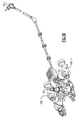
- FIG 1A schematically illustrates an exemplary vertical takeoff and landing (VTOL) rotary-wing aircraft 10.
- the aircraft 10 in the disclosed, non-limiting embodiment includes a main rotor system 12 supported by an airframe 14 having an extending tail 16 which mounts an anti-torque system 18.
- the main rotor assembly 12 is driven about an axis of rotation A through a main rotor gearbox (MGB) 20 by a multi-engine powerplant system 22 - here having two engine packages ENG1, ENG2 (also illustrated in Figure 1B ).
- the multi-engine powerplant system 22 generates the power available for flight operations and couples such power to the main rotor assembly 12 and the anti-torque system 18 through the MGB 20.
- the main rotor system 12 includes a multiple of rotor blades 24 mounted to a rotor hub 26 driven by a main rotor shaft 28 ( Figure 1B ). Although a particular helicopter configuration is illustrated and described in the disclosed embodiment, other configurations and/or machines, which have a rotating frame of reference and a fixed frame of reference will also benefit herefrom.
- the main rotor shaft 28 is a rotational hollow shaft driven by the MGB 20.
- the main rotor shaft 28 is contained within a rotating frame of reference R while the MGB 20 is contained within a fixed frame of reference F.
- An upper section 28U the main rotor shaft 28 generally supports the rotor hub 26 while a lower section 28L of the main rotor shaft 28 may extend into or at least partially through the MGB 20 such that access to the lower section 28L is attainable from within the fixed frame of reference such as from within the MGB 20 and/or airframe 14 ( Figure 1C ).
- main rotor shaft 28 is illustrated in the disclosed non-limiting embodiment as a free space waveguide which provides for wireless communication between a rotating frame of reference R and a fixed frame of reference F
- any hollow shaft type structure such as the tail rotor shaft 18T ( Figure 1B ), a shaft of a gas turbine engine or a shaft of an electrical generator may alternatively or additionally be utilized.
- other systems which may have heretofor utilized slip ring technology such as sensor turrets and weapon stations which require unrestrained rotation and data transmission may also benefit from that disclosed herein.
- the hollow shaft type structure may also include non-metallic and composite materials provided that the materials sufficiently attenuate Radio Frequency (RF) energy.
- RF Radio Frequency
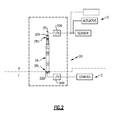
- a communication system 30 includes a communication module 30A located within the rotating frame of reference R and a communication module 30B located within the fixed frame of reference F to provide for wireless communication therebetween.
- wireless communication includes all forms of electromagnetic radiation, including light of visible and non-visible frequencies.
- Such wireless communication facilitates wireless communication of, for example, data between a system S such as a sensor system, actuator system or other system within the rotating frame of reference R with, for example, a control system C within the fixed frame of reference F.
- the wireless communication facilitates operations within the rotating frame of reference R such as on-blade actions, individual blade control, transmission of blade position data and other high bandwidth signal transmission data with the fixed frame of reference F.
- the communication system 30 may be utilized to provide wireless communication between various additional or alternative systems and subsystems.
- the communication module 30A within the rotating frame of reference R may be located adjacent the hub 26 ( Figure 1C ) to minimize G loading thereon.
- the connection between communication module 30A and sensors and actuators of system S may be by any convenient means, for example, by direct wired connection or by wireless.
- An antenna 32A from the communication module 30A adjacent the upper section 28U the main rotor shaft 28 provides for wireless communication with a communication module 30B at least partially through the main rotor shaft 28.
- the communication module 30B within the fixed frame of reference F may be located adjacent the MGB 20 with an antenna 32B therefrom adjacent the lower section 28L of the main rotor shaft 28 to provide for wireless communication with the communication module 30A at least partially through the main rotor shaft 28.
- the communication module 30B need not be connected to the main rotor shaft 28 and may be fixed to the MGB 20 and/or airframe 14.
- the main rotor shaft 28 may be sealed at the upper section 28U by a conductive cover 34 that has provisions for the antenna 32A without compromise of the RF integrity of the main rotor shaft 28.
- the conductive cover 34 prevents radiation from escaping into the environment so as to maintain a covert system and prevents radiation from the external environment from interference with transmission/reception of the communication system 30 as well as prevent external jamming thereof.
- the main rotor shaft 28 operates as a free space electromagnetic waveguide to facilitate wireless communication therein above a cutoff frequency (Fco) without interference from EMI or emission of detectable radiation.
- the main rotor shaft 28 is defacto a Faraday cage.
- the cutoff frequency (Fco) of an electromagnetic waveguide is the lowest frequency for which a mode will propagate. Consequently, a waveguide below the cutoff frequency will result in high levels of attenuation for frequencies below the Fco.
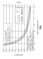
- Figure 4 illustrates a plot of the rectangular and circular equations along with plots of their respective Fco. These plots provide the attenuation per inch of length for a rectangular or a circular waveguide with width and diameter dimensions ranging from approximately 0.1 to 1.4 in. for RF energy that enters the main rotor shaft 28.
- the Fco scale shows the corresponding frequency limits where the waveguide dimensions no longer provide the corresponding attenuation values. It should be understood that frequencies below the cutoff frequency (Fco) result in significant attenuation which will typically prevent effective wireless communication. Waveguides also have a small increase in attenuation with frequency above Fco and are generally considered usable between 1.3 times Fco and 0.9 times the cutoff of the next dominant mode.
- the usable frequency bands for complex waveguide geometries and terminations are typically determined experimentally.
- the main rotor shaft 28 may be highly reflective internally and possibly resonant at the frequencies of interest for the communication modules 30A, 30B.
- the placement of antennas 32A, 32B may thereby be optimized for maximum signal to noise and, because of the waveguide effects provided by the main rotor shaft 28, the RF path loss will be approximately linear with distance rather than the inverse square.
- the main rotor shaft 28 will typically have an inner diameter 28D which is not of a constant inside diameter ( Figure 5 ) and the antenna 32A, 32B may receive a complex impedance, dependant on the antenna pattern.
- This means that the antenna pattern and matching network may be readily optimized for the non-constant inside diameter environment of the main rotor shaft 28 to achieve optimized performance. These optimizations provide for energy efficient and reliable operation.
- Optimized performance may be achieved, for example, through testing, modeling and measurement or other direct analysis of the main rotor shaft 28.
- the optimized performance may be achieved through Orthogonal Frequency Division Multiplexing (OFDM).
- OFDM provides for digital modulation in which a signal is split into several narrowband channels at different frequencies to minimize any interference in an essentially active manner.
- ECC error correcting codes
- power for the communication module 30A in the rotating frame of reference R may be provided by a battery. Optimization of the antenna pattern and matching network will facilitate efficient power usage and thereby increases battery life.
- power generation in the rotating frame of reference R may be provided by the rotation of the main rotor shaft 28 which operates as a rotor of an electrical generator to power the communication module 30A within the rotating frame of reference R.
- the main rotor shaft 28 operates as a waveguide for wireless signals of sufficiently high frequency above the waveguide cutoff frequency which, for a main rotor shaft 28 inside diameter of about 1.4inches (3.5cm) may be on the order of 5-6 GHz.
- FIG. 2 While the embodiment schematically illustrated in Figure 2 , generally locates the communication modules 30A, 30B at the end segments 28U, 28L of the main rotor shaft 28, alternate communication module 30A, 30B placements will benefit herefrom.
- a multiple of communication modules 30C on or about the exterior of the aircraft may communicate with the communication module 30A adjacent the upper segment of the main rotor shaft 28 such that the communication modules 30A operates as a relay in, for example, a point-to-point or mesh network to communicate data from within and without the aircraft ( Figure 6 ).
- another disclosed non-limiting embodiment locates an internal hollow shaft 40 of a constant diameter within the inner diameter 28D of the main rotor shaft 28.
- the internal hollow shaft 40 is of a consistent diameter as compared to the variable inner diameter 28D, the waveguide performance optimization of the internal hollow shaft 40 is relatively less complicated.
- communication lines, conduits and other transmission or structural members may be readily located external to the internal hollow shaft 40 but within the inner diameter 28D.
- a communication line 50 such as a coaxial cable, optical fiber, micro strip or other communication line from the system S within the rotating frame of reference R adjacent an upper section 28U of the main rotor shaft 28 is hard-wired to a lower section 28L of the main rotor shaft 28 but still within the rotating frame of reference R.
- the communication module 30A' is in wireless communication with another nearby communication module 30B' within the fixed frame of reference F.
- An interface 56 with a rotational antenna 58 and fixed antenna 60 which are in relatively close proximity provides for wireless communication with a relatively lower frequency of operation due to the proximity therebetween. It should be understood that the communication module may be of various forms so as to support the interface 56 therebetween.
- an interface 58 which includes a rotating probe 62 in the rotating frame of reference R with a fixed pickup coil 64 within the fixed frame of reference to provide for wireless communication therebetween.
- a rotating probe 62 in the rotating frame of reference R with a fixed pickup coil 64 within the fixed frame of reference to provide for wireless communication therebetween.
- various other interfaces in relative close proximity may alternatively or additionally be utilized.
- various transmission interfaces may alternatively be utilized which accommodates the MGB 20 ( Figure 1B ) as well as other components adjacent the fixed frame of reference.
- a second probe may be used in place of coil 64 or concentric coils may alternatively be used so that a distance or orientation between transmitting and receiving interfaces will not vary with rotation.
Landscapes
- Engineering & Computer Science (AREA)
- Aviation & Aerospace Engineering (AREA)
- Physics & Mathematics (AREA)
- Astronomy & Astrophysics (AREA)
- General Physics & Mathematics (AREA)
- Remote Sensing (AREA)
- Mechanical Engineering (AREA)
- Arrangements For Transmission Of Measured Signals (AREA)
Abstract
Description
- The present disclosure relates to transmission of data, and more particularly to the wireless transmission of data between a rotating frame of reference and a fixed frame of reference.
- The transmission of data between a rotating frame of reference and a fixed frame of reference is typically accommodated through an electrical slip ring. Unique demands are particularly placed on slip ring technology in aerospace applications such as that between a rotor system and an airframe of a rotary-wing aircraft because of equipment requirements and environmental conditions. Such demands are further intensified by the continued desire to transmit more data at higher reliability to, for example, transmit flight control and blade position data.
- Wireless transmission of data may be effective, however, the reliability of wireless transmission may be complicated by arbitrary electromagnetic interference (EMI) typical in the operational environment of aircraft. Further, wireless transmissions may result in emission of detectable radiation which may compromise the aircraft.
- A communication system according to an exemplary aspect of the present disclosure includes a first communication module within a rotating frame of reference and a second communication module within a fixed frame of reference. The first communication module and the second communication module in wireless communication at least partially through a hollow shaft.
- A method of communication according to an exemplary aspect of the present disclosure includes wireless communication between a rotating frame of reference and a fixed frame of reference at a frequency above a waveguide cutoff frequency define by a hollow shaft within the rotating frame of reference.
- Various features will become apparent to those skilled in the art from the following detailed description of the disclosed non-limiting embodiment. The drawings that accompany the detailed description can be briefly described as follows:
-
Figure 1A is a general perspective view of an exemplary rotary wing aircraft embodiment for use with the present invention; -
Figure 1B is a schematic view of a drive system of a rotary-wing aircraft; -
Figure 1C is a schematic view of a main rotor system of a rotary-wing aircraft; -
Figure 2 is a schematic view of a non-limiting embodiment of a wireless transmission system which utilizes a main rotor shaft of a rotary-wing aircraft as a waveguide; -
Figure 3 is a plot of the attenuation per unit length equation for several sizes of rectangular waveguides with width dimensions from 0.1 to 2 in. with a 5:1 L/W ratio; -
Figure 4 illustrates a plot of rectangular and circular equations along with plots of their respective cutoff frequencies Fco in GHz; -
Figure 5 is a schematic view of a main rotor shaft illustrating a non-constant inner diameter waveguide; -
Figure 6 is a schematic view of a distributed wireless communication system; -
Figure 7 is a schematic view of a non-limiting embodiment of a wireless transmission system which utilizes a constant diameter waveguide within a main rotor shaft of a rotary-wing aircraft; -
Figure 8 is a schematic view of another non-limiting embodiment of a wireless transmission system which utilizes a main rotor shaft of a rotary-wing aircraft as a waveguide; and -
Figure 9 is a schematic view of another non-limiting embodiment of a wireless transmission system which utilizes a main rotor shaft of a rotary-wing aircraft as a waveguide. -
Figure 1A schematically illustrates an exemplary vertical takeoff and landing (VTOL) rotary-wing aircraft 10. Theaircraft 10 in the disclosed, non-limiting embodiment includes amain rotor system 12 supported by anairframe 14 having an extendingtail 16 which mounts ananti-torque system 18. Themain rotor assembly 12 is driven about an axis of rotation A through a main rotor gearbox (MGB) 20 by a multi-engine powerplant system 22 - here having two engine packages ENG1, ENG2 (also illustrated inFigure 1B ). Themulti-engine powerplant system 22 generates the power available for flight operations and couples such power to themain rotor assembly 12 and theanti-torque system 18 through the MGB 20. Themain rotor system 12 includes a multiple ofrotor blades 24 mounted to arotor hub 26 driven by a main rotor shaft 28 (Figure 1B ). Although a particular helicopter configuration is illustrated and described in the disclosed embodiment, other configurations and/or machines, which have a rotating frame of reference and a fixed frame of reference will also benefit herefrom. - Referring to
Figure 1B , themain rotor shaft 28 is a rotational hollow shaft driven by the MGB 20. Themain rotor shaft 28 is contained within a rotating frame of reference R while theMGB 20 is contained within a fixed frame of reference F. Anupper section 28U themain rotor shaft 28 generally supports therotor hub 26 while alower section 28L of themain rotor shaft 28 may extend into or at least partially through theMGB 20 such that access to thelower section 28L is attainable from within the fixed frame of reference such as from within theMGB 20 and/or airframe 14 (Figure 1C ). - It should be understood that although the
main rotor shaft 28 is illustrated in the disclosed non-limiting embodiment as a free space waveguide which provides for wireless communication between a rotating frame of reference R and a fixed frame of reference F, any hollow shaft type structure such as thetail rotor shaft 18T (Figure 1B ), a shaft of a gas turbine engine or a shaft of an electrical generator may alternatively or additionally be utilized. Additionally, other systems which may have heretofor utilized slip ring technology such as sensor turrets and weapon stations which require unrestrained rotation and data transmission may also benefit from that disclosed herein. The hollow shaft type structure may also include non-metallic and composite materials provided that the materials sufficiently attenuate Radio Frequency (RF) energy. - Referring to
Figure 2 , acommunication system 30 includes acommunication module 30A located within the rotating frame of reference R and acommunication module 30B located within the fixed frame of reference F to provide for wireless communication therebetween. In particular, it should be understood that wireless communication includes all forms of electromagnetic radiation, including light of visible and non-visible frequencies. Such wireless communication facilitates wireless communication of, for example, data between a system S such as a sensor system, actuator system or other system within the rotating frame of reference R with, for example, a control system C within the fixed frame of reference F. The wireless communication facilitates operations within the rotating frame of reference R such as on-blade actions, individual blade control, transmission of blade position data and other high bandwidth signal transmission data with the fixed frame of reference F. It should be understood that thecommunication system 30 may be utilized to provide wireless communication between various additional or alternative systems and subsystems. - The
communication module 30A within the rotating frame of reference R may be located adjacent the hub 26 (Figure 1C ) to minimize G loading thereon. The connection betweencommunication module 30A and sensors and actuators of system S may be by any convenient means, for example, by direct wired connection or by wireless. Anantenna 32A from thecommunication module 30A adjacent theupper section 28U themain rotor shaft 28 provides for wireless communication with acommunication module 30B at least partially through themain rotor shaft 28. Thecommunication module 30B within the fixed frame of reference F may be located adjacent theMGB 20 with anantenna 32B therefrom adjacent thelower section 28L of themain rotor shaft 28 to provide for wireless communication with thecommunication module 30A at least partially through themain rotor shaft 28. Thecommunication module 30B need not be connected to themain rotor shaft 28 and may be fixed to theMGB 20 and/orairframe 14. - The
main rotor shaft 28 may be sealed at theupper section 28U by aconductive cover 34 that has provisions for theantenna 32A without compromise of the RF integrity of themain rotor shaft 28. Theconductive cover 34 prevents radiation from escaping into the environment so as to maintain a covert system and prevents radiation from the external environment from interference with transmission/reception of thecommunication system 30 as well as prevent external jamming thereof. Themain rotor shaft 28 operates as a free space electromagnetic waveguide to facilitate wireless communication therein above a cutoff frequency (Fco) without interference from EMI or emission of detectable radiation. Themain rotor shaft 28 is defacto a Faraday cage. - The cutoff frequency (Fco) of an electromagnetic waveguide is the lowest frequency for which a mode will propagate. Consequently, a waveguide below the cutoff frequency will result in high levels of attenuation for frequencies below the Fco.
- The lowest Fco for a rectangular waveguide and a circular waveguide is given by the following equations:
-

-

where: - W = width in inches; and
- D = diameter in inches
- Below the Fco, the attenuation per unit length (inches) at any frequency (F) is given by:

where: - AUL = attenuation per unit length
- F is in MHz
- Although this equation provides the attenuation per unit length, the designer using these relationships should strive for at least a 3:1 length-to-width (L/W) or diameter ratio as generally disclosed in
Figure 3 . Regardless of the width, for frequencies below approximately Fco/3, the attenuation is almost independent of frequency. When the frequencies are below Fco/10, the quantity:
approaches (Fco/F). The attenuation per unit length can thus be approximated as:
- After substituting the appropriate Fco for the rectangular and circular waveguide, the attenuation per unit length reduces to:
-

-

where: - W = width in inches; and
- D = diameter in inches.
-
Figure 4 illustrates a plot of the rectangular and circular equations along with plots of their respective Fco. These plots provide the attenuation per inch of length for a rectangular or a circular waveguide with width and diameter dimensions ranging from approximately 0.1 to 1.4 in. for RF energy that enters themain rotor shaft 28. The Fco scale shows the corresponding frequency limits where the waveguide dimensions no longer provide the corresponding attenuation values. It should be understood that frequencies below the cutoff frequency (Fco) result in significant attenuation which will typically prevent effective wireless communication. Waveguides also have a small increase in attenuation with frequency above Fco and are generally considered usable between 1.3 times Fco and 0.9 times the cutoff of the next dominant mode. The usable frequency bands for complex waveguide geometries and terminations are typically determined experimentally. - The
main rotor shaft 28 may be highly reflective internally and possibly resonant at the frequencies of interest for thecommunication modules antennas main rotor shaft 28, the RF path loss will be approximately linear with distance rather than the inverse square. - The
main rotor shaft 28 will typically have aninner diameter 28D which is not of a constant inside diameter (Figure 5 ) and theantenna main rotor shaft 28 to achieve optimized performance. These optimizations provide for energy efficient and reliable operation. - Optimized performance may be achieved, for example, through testing, modeling and measurement or other direct analysis of the
main rotor shaft 28. Alternatively, the optimized performance may be achieved through Orthogonal Frequency Division Multiplexing (OFDM). OFDM provides for digital modulation in which a signal is split into several narrowband channels at different frequencies to minimize any interference in an essentially active manner. - Dependant at least in part on the design of the
antenna main rotor shaft 28 structures, there will likely be signal strength modulation from the respective motion of theantennas main rotor shaft 28 and only communicate when good SNR occurs. The synchronization may be determined analytically, but need not be. Furthermore, instead of a function of shaft angle, synchronization may be determined experimentally. It should be understood that any combination of these techniques may alternatively or additionally be utilized such that, for example only, adequate power, ECC, and synchronization may be utilized in combination. - In one non-limiting embodiment, power for the
communication module 30A in the rotating frame of reference R may be provided by a battery. Optimization of the antenna pattern and matching network will facilitate efficient power usage and thereby increases battery life. Alternatively, power generation in the rotating frame of reference R may be provided by the rotation of themain rotor shaft 28 which operates as a rotor of an electrical generator to power thecommunication module 30A within the rotating frame of reference R. - The
main rotor shaft 28 operates as a waveguide for wireless signals of sufficiently high frequency above the waveguide cutoff frequency which, for amain rotor shaft 28 inside diameter of about 1.4inches (3.5cm) may be on the order of 5-6 GHz. - While the embodiment schematically illustrated in
Figure 2 , generally locates thecommunication modules end segments main rotor shaft 28,alternate communication module communication modules 30C on or about the exterior of the aircraft may communicate with thecommunication module 30A adjacent the upper segment of themain rotor shaft 28 such that thecommunication modules 30A operates as a relay in, for example, a point-to-point or mesh network to communicate data from within and without the aircraft (Figure 6 ). - Referring to
Figure 7 , another disclosed non-limiting embodiment locates an internalhollow shaft 40 of a constant diameter within theinner diameter 28D of themain rotor shaft 28. Whereas the internalhollow shaft 40 is of a consistent diameter as compared to the variableinner diameter 28D, the waveguide performance optimization of the internalhollow shaft 40 is relatively less complicated. Furthermore, communication lines, conduits and other transmission or structural members may be readily located external to the internalhollow shaft 40 but within theinner diameter 28D. - Referring to
Figure 8 , another disclosed non-limiting embodiment provides for a lower frequency of operation to conduct the wireless communication through themain rotor shaft 28. Acommunication line 50 such as a coaxial cable, optical fiber, micro strip or other communication line from the system S within the rotating frame of reference R adjacent anupper section 28U of themain rotor shaft 28 is hard-wired to alower section 28L of themain rotor shaft 28 but still within the rotating frame of reference R. Thecommunication module 30A' is in wireless communication with anothernearby communication module 30B' within the fixed frame of referenceF. An interface 56 with arotational antenna 58 and fixedantenna 60 which are in relatively close proximity provides for wireless communication with a relatively lower frequency of operation due to the proximity therebetween. It should be understood that the communication module may be of various forms so as to support theinterface 56 therebetween. - Referring to
Figure 9 , another disclosed non-limiting embodiment utilizes aninterface 58 which includes arotating probe 62 in the rotating frame of reference R with a fixedpickup coil 64 within the fixed frame of reference to provide for wireless communication therebetween. It should be understood that various other interfaces in relative close proximity may alternatively or additionally be utilized. It should be understood that various transmission interfaces may alternatively be utilized which accommodates the MGB 20 (Figure 1B ) as well as other components adjacent the fixed frame of reference. For instance, a second probe may be used in place ofcoil 64 or concentric coils may alternatively be used so that a distance or orientation between transmitting and receiving interfaces will not vary with rotation. - It should be understood that like reference numerals identify corresponding or similar elements throughout the several drawings. It should also be understood that although a particular component arrangement is disclosed in the illustrated embodiment, other arrangements will benefit herefrom.
- Although particular step sequences are shown, described, and claimed, it should be understood that steps may be performed in any order, separated or combined unless otherwise indicated and will still benefit from the present invention.
- The foregoing description is exemplary rather than defined by the limitations within. Various non-limiting embodiments are disclosed herein, however, one of ordinary skill in the art would recognize that various modifications and variations in light of the above teachings will fall within the scope of the appended claims. It is therefore to be understood that within the scope of the appended claims, the invention may be practiced other than as specifically described. For that reason the appended claims should be studied to determine true scope and content.
Claims (15)
- A communication system comprising:a first communication module (30A) within a rotating frame of reference;a second communication module (30B) within a fixed frame of reference; anda hollow shaft (28) at least partially within said rotating frame of reference, said first communication module (30A) and said second communication module (30B) being in wireless communication at least partially through said hollow shaft (28).
- The system as recited in claim 1, wherein said first communication module (30A) is a transmitter and said second communication module (30B) is a receiver.
- The system as recited in claim 1 or 2, wherein each of said first communication module (30A) and said second communication module (30B) is a transceiver.
- The system as recited in any of claims 1 to 3, wherein said hollow shaft (28) is a main rotor shaft of a rotary wing aircraft (10), said main rotor shaft rotatable about an axis of rotation (A).
- The system as recited in claim 4, wherein said hollow shaft (28) is of a non-constant inner diameter (28D) formed within said main rotor shaft.
- The system as recited in any of claims 1 to 5, wherein said hollow shaft (28) is fixed within a main rotor shaft of a rotary wing aircraft (10), said main rotor shaft being rotatable about an axis of rotation (A).
- The system as recited in claim 6, wherein said hollow shaft (28) is of a constant inner diameter.
- The system as recited in any of claims 1 to 7, wherein said wireless communication is at a frequency above a waveguide cutoff frequency define by said hollow shaft (28).
- The system as recited in any of claims 1 to 8, further comprising a sensor within said rotating frame of reference, said sensor being in communication with said first communication module (30A) through a communication line through said hollow shaft (28), said first communication module (30A) being in close proximity to said second communication module (30B).
- The system as recited in any of claims 1 to 9, further comprising a communication line connected to said first communication module (30A) and a first antenna (32A) within said rotating frame of reference, said first antenna (32A) being in close proximity to a second antenna (32B) of said second communication module (30B).
- The system as recited in claim 10, wherein said first antenna (32A) is a rotating disk antenna and said second antenna (32B) is a fixed disk antenna..
- The system as recited in claim 10 or 11, wherein said first antenna (32A) is a probe and said second antenna (32B) is a coil, or probe.
- The system as recited in any of claims 10 to 12, wherein said communication line is an optical fiber.
- A method of wireless communication comprising:wireless communicating between a rotating frame of reference and a fixed frame of reference at a frequency above a waveguide cutoff frequency defined by a hollow shaft (28) at least partially within the rotating frame of reference.
- A method as recited in claim 14, wherein the hollow shaft (28) is a main rotor shaft of a rotary-wing aircraft (10).
Applications Claiming Priority (1)
| Application Number | Priority Date | Filing Date | Title |
|---|---|---|---|
| US12/393,003 US8384605B2 (en) | 2009-02-25 | 2009-02-25 | Wireless communication between a rotating frame of reference and a non-rotating frame of reference |
Publications (2)
| Publication Number | Publication Date |
|---|---|
| EP2224536A1 true EP2224536A1 (en) | 2010-09-01 |
| EP2224536B1 EP2224536B1 (en) | 2012-06-06 |
Family
ID=42115574
Family Applications (1)
| Application Number | Title | Priority Date | Filing Date |
|---|---|---|---|
| EP10154558A Not-in-force EP2224536B1 (en) | 2009-02-25 | 2010-02-24 | Wireless communication between a rotating frame of reference and a non-rotating frame of reference |
Country Status (2)
| Country | Link |
|---|---|
| US (1) | US8384605B2 (en) |
| EP (1) | EP2224536B1 (en) |
Cited By (2)
| Publication number | Priority date | Publication date | Assignee | Title |
|---|---|---|---|---|
| EP2433866A3 (en) * | 2010-09-28 | 2015-03-25 | Simmonds Precision Products, Inc. | Wireless rotor track and balance system for rotorcraft |
| FR3083406A1 (en) * | 2018-06-28 | 2020-01-03 | Airbus Helicopters | OPTICAL TRANSMISSION SYSTEM AND AIRCRAFT |
Families Citing this family (5)
| Publication number | Priority date | Publication date | Assignee | Title |
|---|---|---|---|---|
| FR2986393B1 (en) | 2012-01-30 | 2014-11-07 | Eurocopter France | COMMUNICATION DEVICE, AIRCRAFT ROTOR AND AIRCRAFT |
| FR2988075B1 (en) | 2012-03-19 | 2014-04-25 | Eurocopter France | DEVICE FOR MONITORING THE BEHAVIOR AND / OR TRAINING BEHAVIOR OF A ROTOR BLADE OF A GIRAVION |
| FR2990236B1 (en) | 2012-05-07 | 2014-04-25 | Eurocopter France | CONTROL DEVICE BY DEPRESSURIZING THE SEALING OF A TRANSMISSION BOX OF A GIRAVION |
| US9203459B2 (en) * | 2013-04-18 | 2015-12-01 | Sikorsky Aircraft Corporation | Harmonic data transfer in rotary wing aircraft |
| US11724818B2 (en) | 2020-09-21 | 2023-08-15 | Rockwell Collins, Inc. | Phased array transmission reflected off rotor blade to target |
Citations (6)
| Publication number | Priority date | Publication date | Assignee | Title |
|---|---|---|---|---|
| US3390393A (en) * | 1964-09-17 | 1968-06-25 | Bell Aerospace Corp | Airfoil radar antenna |
| US3681714A (en) * | 1969-03-06 | 1972-08-01 | Tokyo Keiki Seizosho Co Ltd | Impedance transformers for microwave transmission lines |
| US3701157A (en) * | 1971-06-03 | 1972-10-24 | Us Air Force | Helicopter uhf antenna system for satellite communications |
| US3896446A (en) * | 1972-07-13 | 1975-07-22 | Mitsubishi Electric Corp | Radar mounted on helicopter |
| DE4328573A1 (en) * | 1993-08-25 | 1995-03-09 | Deutsche Aerospace | All-weather sight system for helicopters |
| WO2002011231A1 (en) * | 2000-08-02 | 2002-02-07 | Schleifring Und Apparatebau Gmbh | Device for carrying out the non-contact rotational transmission of high-frequency signals |
Family Cites Families (31)
| Publication number | Priority date | Publication date | Assignee | Title |
|---|---|---|---|---|
| US3972491A (en) * | 1975-07-14 | 1976-08-03 | United Technologies Corporation | Two-position helicopter main rotor |
| US4524620A (en) * | 1983-02-07 | 1985-06-25 | Hughes Helicopters, Inc. | In-flight monitoring of composite structural components such as helicopter rotor blades |
| US7421321B2 (en) * | 1995-06-07 | 2008-09-02 | Automotive Technologies International, Inc. | System for obtaining vehicular information |
| US7103460B1 (en) * | 1994-05-09 | 2006-09-05 | Automotive Technologies International, Inc. | System and method for vehicle diagnostics |
| US7313467B2 (en) * | 2000-09-08 | 2007-12-25 | Automotive Technologies International Inc. | System and method for in-vehicle communications |
| US5614907A (en) * | 1996-03-14 | 1997-03-25 | Daimler-Benz Aerospace Ag | All weather visual system for helicopters |
| US6171056B1 (en) * | 1998-12-23 | 2001-01-09 | Sikorsky Aircraft Corporation | Technique for providing a signal for controlling blade vortex interaction noise of a rotorcraft |
| US6200096B1 (en) * | 1999-04-16 | 2001-03-13 | Sikorsky Aircraft Corporation | Actuation system for an active rotor control system |
| US6295006B1 (en) * | 1999-04-16 | 2001-09-25 | Sikorsky Aircraft Corporation | Flap angle measurement system for an active rotor control system |
| US6196796B1 (en) * | 1999-04-22 | 2001-03-06 | Sikorsky Aircraft Corporation | High torque actuation system for an active rotor control system |
| SE514818C2 (en) | 1999-04-30 | 2001-04-30 | Abb Ab | Constant frequency machine with varying / variable speed and procedure for such machine |
| US6477465B1 (en) * | 1999-11-29 | 2002-11-05 | American Gnc Corporation | Vehicle self-carried positioning method and system thereof |
| US6322324B1 (en) * | 2000-03-03 | 2001-11-27 | The Boeing Company | Helicopter in-flight rotor tracking system, method, and smart actuator therefor |
| US6354536B1 (en) * | 2000-08-08 | 2002-03-12 | Sikorsky Aircraft Corporation | Rotor hub mounted actuator for controlling a blade on a rotorcraft |
| JP3726693B2 (en) * | 2001-03-29 | 2005-12-14 | 三菱電機株式会社 | Antenna device |
| US6693548B2 (en) * | 2001-08-08 | 2004-02-17 | Sikorsky Aircraft Corporation | Structural monitoring system for helicopter rotor components |
| US6714135B2 (en) * | 2001-11-08 | 2004-03-30 | Bell Helicopter Textron, Inc. | Collective head bearing monitor |
| US6968508B2 (en) * | 2002-07-30 | 2005-11-22 | Motorola, Inc. | Rotating user interface |
| US6950073B2 (en) * | 2002-08-20 | 2005-09-27 | Aerosat Corporation | Communication system with broadband antenna |
| US20040229478A1 (en) * | 2003-05-13 | 2004-11-18 | Chen Chao Ming | Rotatory wireless USB network interface card |
| US6908286B2 (en) * | 2003-07-10 | 2005-06-21 | Sikorsky Aircraft Corporation | Main rotor shaft mounted hydraulic pressure system |
| US6941817B2 (en) * | 2003-08-26 | 2005-09-13 | Delphi Technologies, Inc. | Shaft delashing method and assembly with wireless interface |
| US7604198B2 (en) * | 2003-09-25 | 2009-10-20 | Petersen Bruce L | Rotorcraft having coaxial counter-rotating rotors which produce both vertical and horizontal thrust and method of controlled flight in all six degrees of freedom |
| US7086834B2 (en) * | 2004-06-10 | 2006-08-08 | General Electric Company | Methods and apparatus for rotor blade ice detection |
| US7090178B2 (en) * | 2004-08-10 | 2006-08-15 | Flir Systems Inc. | Sealed rotary joint for turret rotator |
| FR2878227B1 (en) * | 2004-11-23 | 2008-05-23 | Eurocopter France | SYSTEM FOR MONITORING THE DAMAGE OF AN AIRCRAFT AIR ROTOR BLADE WITH ROTARY WING |
| US7606592B2 (en) * | 2005-09-19 | 2009-10-20 | Becker Charles D | Waveguide-based wireless distribution system and method of operation |
| US7324016B1 (en) * | 2005-11-22 | 2008-01-29 | The United States Of America As Represented By The Secretary Of The Navy | Navigational indicating system for rotary wing aircraft |
| US7355302B2 (en) * | 2005-11-23 | 2008-04-08 | Ice Corporation | System and method for providing power and control through a rotating interface |
| US7437264B2 (en) * | 2006-06-19 | 2008-10-14 | General Electric Company | Methods and apparatus for balancing a rotor |
| US7893789B2 (en) * | 2006-12-12 | 2011-02-22 | Andrew Llc | Waveguide transitions and method of forming components |
-
2009
- 2009-02-25 US US12/393,003 patent/US8384605B2/en not_active Expired - Fee Related
-
2010
- 2010-02-24 EP EP10154558A patent/EP2224536B1/en not_active Not-in-force
Patent Citations (6)
| Publication number | Priority date | Publication date | Assignee | Title |
|---|---|---|---|---|
| US3390393A (en) * | 1964-09-17 | 1968-06-25 | Bell Aerospace Corp | Airfoil radar antenna |
| US3681714A (en) * | 1969-03-06 | 1972-08-01 | Tokyo Keiki Seizosho Co Ltd | Impedance transformers for microwave transmission lines |
| US3701157A (en) * | 1971-06-03 | 1972-10-24 | Us Air Force | Helicopter uhf antenna system for satellite communications |
| US3896446A (en) * | 1972-07-13 | 1975-07-22 | Mitsubishi Electric Corp | Radar mounted on helicopter |
| DE4328573A1 (en) * | 1993-08-25 | 1995-03-09 | Deutsche Aerospace | All-weather sight system for helicopters |
| WO2002011231A1 (en) * | 2000-08-02 | 2002-02-07 | Schleifring Und Apparatebau Gmbh | Device for carrying out the non-contact rotational transmission of high-frequency signals |
Cited By (2)
| Publication number | Priority date | Publication date | Assignee | Title |
|---|---|---|---|---|
| EP2433866A3 (en) * | 2010-09-28 | 2015-03-25 | Simmonds Precision Products, Inc. | Wireless rotor track and balance system for rotorcraft |
| FR3083406A1 (en) * | 2018-06-28 | 2020-01-03 | Airbus Helicopters | OPTICAL TRANSMISSION SYSTEM AND AIRCRAFT |
Also Published As
| Publication number | Publication date |
|---|---|
| US8384605B2 (en) | 2013-02-26 |
| EP2224536B1 (en) | 2012-06-06 |
| US20100216398A1 (en) | 2010-08-26 |
Similar Documents
| Publication | Publication Date | Title |
|---|---|---|
| EP2224536B1 (en) | Wireless communication between a rotating frame of reference and a non-rotating frame of reference | |
| EP2849284B1 (en) | Integrated antenna transceiver for sensor and data transmission on rotating shafts | |
| EP3826192B1 (en) | Radio frequency-based repeater in a waveguide system | |
| RU2686805C2 (en) | Wireless sensor system and methods for use thereof | |
| US8948928B2 (en) | Sustained over-the-horizon vertical takeoff and landing sensing system | |
| US20070176840A1 (en) | Multi-receiver communication system with distributed aperture antenna | |
| US9909916B2 (en) | Wireless fuel sensor system | |
| EP3709439A1 (en) | Wideband antenna system components in rotary aircraft rotors | |
| US11698348B2 (en) | Self-referencing microwave sensing system | |
| RU2678760C2 (en) | Wireless fuel sensor system | |
| EP2886887B1 (en) | Ball-and-socket joint incorporating a device for measuring the wear and method for measuring the wear of such a ball-and-socket joint | |
| EP3346552B1 (en) | Remote data concentrator self-test | |
| US8957816B2 (en) | Communication device, an aircraft rotor, and an aircraft | |
| US8462058B2 (en) | Aircraft antenna | |
| EP3000190B1 (en) | Data retrieval system in an aircraft with data stored during a flight and wirelessly transmitted to a ground system after landing using a transmission element in an external panel of an avionic bay. | |
| CN112298525B (en) | Method for electromagnetic compatibility of platform load based on solar UAV, solar UAV | |
| EP4164052A1 (en) | Waveguide system | |
| US20160119053A1 (en) | Data retrieval system in an aircraft with data stored during a flight and wirelessly transmitted to a ground system after landing at a frequency in the range of 50-330 ghz or 22-24 ghz | |
| EP4624727A1 (en) | Wireless telemetry module system for an aircraft engine | |
| US10784568B1 (en) | System and method for retrofitting digital antenna arrays | |
| RU2427508C1 (en) | System for remote control over space rocket complex on launch pad | |
| CN208548447U (en) | A kind of unmanned plane antenna and unmanned plane | |
| CA2313937A1 (en) | Communication system for transmitting data between first and second platforms in relative rotation, and a method thereof | |
| GB2515272A (en) | Aircraft data retrieval |
Legal Events
| Date | Code | Title | Description |
|---|---|---|---|
| PUAI | Public reference made under article 153(3) epc to a published international application that has entered the european phase |
Free format text: ORIGINAL CODE: 0009012 |
|
| AK | Designated contracting states |
Kind code of ref document: A1 Designated state(s): AT BE BG CH CY CZ DE DK EE ES FI FR GB GR HR HU IE IS IT LI LT LU LV MC MK MT NL NO PL PT RO SE SI SK SM TR |
|
| AX | Request for extension of the european patent |
Extension state: AL BA RS |
|
| RIN1 | Information on inventor provided before grant (corrected) |
Inventor name: FINN, ALAN MATTHEW Inventor name: YEH, JIMMY LIH-MIN Inventor name: ZACCHIO, JOSEPH Inventor name: O'CALLAGHAN, MICHAEL G. |
|
| 17P | Request for examination filed |
Effective date: 20110222 |
|
| GRAP | Despatch of communication of intention to grant a patent |
Free format text: ORIGINAL CODE: EPIDOSNIGR1 |
|
| RIC1 | Information provided on ipc code assigned before grant |
Ipc: H01Q 1/28 20060101ALI20111129BHEP Ipc: B64C 27/00 20060101ALI20111129BHEP Ipc: B64D 47/00 20060101ALI20111129BHEP Ipc: B64D 45/00 20060101ALI20111129BHEP Ipc: B64C 27/32 20060101ALI20111129BHEP Ipc: H01P 1/06 20060101AFI20111129BHEP |
|
| GRAS | Grant fee paid |
Free format text: ORIGINAL CODE: EPIDOSNIGR3 |
|
| GRAA | (expected) grant |
Free format text: ORIGINAL CODE: 0009210 |
|
| AK | Designated contracting states |
Kind code of ref document: B1 Designated state(s): AT BE BG CH CY CZ DE DK EE ES FI FR GB GR HR HU IE IS IT LI LT LU LV MC MK MT NL NO PL PT RO SE SI SK SM TR |
|
| REG | Reference to a national code |
Ref country code: GB Ref legal event code: FG4D |
|
| REG | Reference to a national code |
Ref country code: AT Ref legal event code: REF Ref document number: 561409 Country of ref document: AT Kind code of ref document: T Effective date: 20120615 Ref country code: CH Ref legal event code: EP |
|
| REG | Reference to a national code |
Ref country code: IE Ref legal event code: FG4D |
|
| REG | Reference to a national code |
Ref country code: DE Ref legal event code: R096 Ref document number: 602010001796 Country of ref document: DE Effective date: 20120802 |
|
| REG | Reference to a national code |
Ref country code: NL Ref legal event code: VDEP Effective date: 20120606 |
|
| PG25 | Lapsed in a contracting state [announced via postgrant information from national office to epo] |
Ref country code: FI Free format text: LAPSE BECAUSE OF FAILURE TO SUBMIT A TRANSLATION OF THE DESCRIPTION OR TO PAY THE FEE WITHIN THE PRESCRIBED TIME-LIMIT Effective date: 20120606 Ref country code: LT Free format text: LAPSE BECAUSE OF FAILURE TO SUBMIT A TRANSLATION OF THE DESCRIPTION OR TO PAY THE FEE WITHIN THE PRESCRIBED TIME-LIMIT Effective date: 20120606 Ref country code: NO Free format text: LAPSE BECAUSE OF FAILURE TO SUBMIT A TRANSLATION OF THE DESCRIPTION OR TO PAY THE FEE WITHIN THE PRESCRIBED TIME-LIMIT Effective date: 20120906 Ref country code: SE Free format text: LAPSE BECAUSE OF FAILURE TO SUBMIT A TRANSLATION OF THE DESCRIPTION OR TO PAY THE FEE WITHIN THE PRESCRIBED TIME-LIMIT Effective date: 20120606 Ref country code: CY Free format text: LAPSE BECAUSE OF FAILURE TO SUBMIT A TRANSLATION OF THE DESCRIPTION OR TO PAY THE FEE WITHIN THE PRESCRIBED TIME-LIMIT Effective date: 20120606 |
|
| REG | Reference to a national code |
Ref country code: AT Ref legal event code: MK05 Ref document number: 561409 Country of ref document: AT Kind code of ref document: T Effective date: 20120606 |
|
| REG | Reference to a national code |
Ref country code: LT Ref legal event code: MG4D Effective date: 20120606 |
|
| PG25 | Lapsed in a contracting state [announced via postgrant information from national office to epo] |
Ref country code: LV Free format text: LAPSE BECAUSE OF FAILURE TO SUBMIT A TRANSLATION OF THE DESCRIPTION OR TO PAY THE FEE WITHIN THE PRESCRIBED TIME-LIMIT Effective date: 20120606 Ref country code: GR Free format text: LAPSE BECAUSE OF FAILURE TO SUBMIT A TRANSLATION OF THE DESCRIPTION OR TO PAY THE FEE WITHIN THE PRESCRIBED TIME-LIMIT Effective date: 20120907 Ref country code: HR Free format text: LAPSE BECAUSE OF FAILURE TO SUBMIT A TRANSLATION OF THE DESCRIPTION OR TO PAY THE FEE WITHIN THE PRESCRIBED TIME-LIMIT Effective date: 20120606 Ref country code: SI Free format text: LAPSE BECAUSE OF FAILURE TO SUBMIT A TRANSLATION OF THE DESCRIPTION OR TO PAY THE FEE WITHIN THE PRESCRIBED TIME-LIMIT Effective date: 20120606 |
|
| PG25 | Lapsed in a contracting state [announced via postgrant information from national office to epo] |
Ref country code: BE Free format text: LAPSE BECAUSE OF FAILURE TO SUBMIT A TRANSLATION OF THE DESCRIPTION OR TO PAY THE FEE WITHIN THE PRESCRIBED TIME-LIMIT Effective date: 20120606 Ref country code: EE Free format text: LAPSE BECAUSE OF FAILURE TO SUBMIT A TRANSLATION OF THE DESCRIPTION OR TO PAY THE FEE WITHIN THE PRESCRIBED TIME-LIMIT Effective date: 20120606 Ref country code: SK Free format text: LAPSE BECAUSE OF FAILURE TO SUBMIT A TRANSLATION OF THE DESCRIPTION OR TO PAY THE FEE WITHIN THE PRESCRIBED TIME-LIMIT Effective date: 20120606 Ref country code: NL Free format text: LAPSE BECAUSE OF FAILURE TO SUBMIT A TRANSLATION OF THE DESCRIPTION OR TO PAY THE FEE WITHIN THE PRESCRIBED TIME-LIMIT Effective date: 20120606 Ref country code: CZ Free format text: LAPSE BECAUSE OF FAILURE TO SUBMIT A TRANSLATION OF THE DESCRIPTION OR TO PAY THE FEE WITHIN THE PRESCRIBED TIME-LIMIT Effective date: 20120606 Ref country code: IS Free format text: LAPSE BECAUSE OF FAILURE TO SUBMIT A TRANSLATION OF THE DESCRIPTION OR TO PAY THE FEE WITHIN THE PRESCRIBED TIME-LIMIT Effective date: 20121006 Ref country code: AT Free format text: LAPSE BECAUSE OF FAILURE TO SUBMIT A TRANSLATION OF THE DESCRIPTION OR TO PAY THE FEE WITHIN THE PRESCRIBED TIME-LIMIT Effective date: 20120606 Ref country code: RO Free format text: LAPSE BECAUSE OF FAILURE TO SUBMIT A TRANSLATION OF THE DESCRIPTION OR TO PAY THE FEE WITHIN THE PRESCRIBED TIME-LIMIT Effective date: 20120606 |
|
| PG25 | Lapsed in a contracting state [announced via postgrant information from national office to epo] |
Ref country code: IT Free format text: LAPSE BECAUSE OF FAILURE TO SUBMIT A TRANSLATION OF THE DESCRIPTION OR TO PAY THE FEE WITHIN THE PRESCRIBED TIME-LIMIT Effective date: 20120606 Ref country code: PL Free format text: LAPSE BECAUSE OF FAILURE TO SUBMIT A TRANSLATION OF THE DESCRIPTION OR TO PAY THE FEE WITHIN THE PRESCRIBED TIME-LIMIT Effective date: 20120606 Ref country code: PT Free format text: LAPSE BECAUSE OF FAILURE TO SUBMIT A TRANSLATION OF THE DESCRIPTION OR TO PAY THE FEE WITHIN THE PRESCRIBED TIME-LIMIT Effective date: 20121008 |
|
| PLBE | No opposition filed within time limit |
Free format text: ORIGINAL CODE: 0009261 |
|
| STAA | Information on the status of an ep patent application or granted ep patent |
Free format text: STATUS: NO OPPOSITION FILED WITHIN TIME LIMIT |
|
| PG25 | Lapsed in a contracting state [announced via postgrant information from national office to epo] |
Ref country code: DK Free format text: LAPSE BECAUSE OF FAILURE TO SUBMIT A TRANSLATION OF THE DESCRIPTION OR TO PAY THE FEE WITHIN THE PRESCRIBED TIME-LIMIT Effective date: 20120606 Ref country code: ES Free format text: LAPSE BECAUSE OF FAILURE TO SUBMIT A TRANSLATION OF THE DESCRIPTION OR TO PAY THE FEE WITHIN THE PRESCRIBED TIME-LIMIT Effective date: 20120917 |
|
| 26N | No opposition filed |
Effective date: 20130307 |
|
| REG | Reference to a national code |
Ref country code: DE Ref legal event code: R097 Ref document number: 602010001796 Country of ref document: DE Effective date: 20130307 |
|
| PG25 | Lapsed in a contracting state [announced via postgrant information from national office to epo] |
Ref country code: BG Free format text: LAPSE BECAUSE OF FAILURE TO SUBMIT A TRANSLATION OF THE DESCRIPTION OR TO PAY THE FEE WITHIN THE PRESCRIBED TIME-LIMIT Effective date: 20120906 |
|
| PG25 | Lapsed in a contracting state [announced via postgrant information from national office to epo] |
Ref country code: MC Free format text: LAPSE BECAUSE OF NON-PAYMENT OF DUE FEES Effective date: 20130228 |
|
| REG | Reference to a national code |
Ref country code: IE Ref legal event code: MM4A |
|
| PG25 | Lapsed in a contracting state [announced via postgrant information from national office to epo] |
Ref country code: IE Free format text: LAPSE BECAUSE OF NON-PAYMENT OF DUE FEES Effective date: 20130224 |
|
| PG25 | Lapsed in a contracting state [announced via postgrant information from national office to epo] |
Ref country code: MT Free format text: LAPSE BECAUSE OF FAILURE TO SUBMIT A TRANSLATION OF THE DESCRIPTION OR TO PAY THE FEE WITHIN THE PRESCRIBED TIME-LIMIT Effective date: 20120606 |
|
| REG | Reference to a national code |
Ref country code: CH Ref legal event code: PL |
|
| PG25 | Lapsed in a contracting state [announced via postgrant information from national office to epo] |
Ref country code: LI Free format text: LAPSE BECAUSE OF NON-PAYMENT OF DUE FEES Effective date: 20140228 Ref country code: CH Free format text: LAPSE BECAUSE OF NON-PAYMENT OF DUE FEES Effective date: 20140228 |
|
| REG | Reference to a national code |
Ref country code: FR Ref legal event code: PLFP Year of fee payment: 6 |
|
| PG25 | Lapsed in a contracting state [announced via postgrant information from national office to epo] |
Ref country code: SM Free format text: LAPSE BECAUSE OF FAILURE TO SUBMIT A TRANSLATION OF THE DESCRIPTION OR TO PAY THE FEE WITHIN THE PRESCRIBED TIME-LIMIT Effective date: 20120606 |
|
| PG25 | Lapsed in a contracting state [announced via postgrant information from national office to epo] |
Ref country code: TR Free format text: LAPSE BECAUSE OF FAILURE TO SUBMIT A TRANSLATION OF THE DESCRIPTION OR TO PAY THE FEE WITHIN THE PRESCRIBED TIME-LIMIT Effective date: 20120606 |
|
| PG25 | Lapsed in a contracting state [announced via postgrant information from national office to epo] |
Ref country code: MK Free format text: LAPSE BECAUSE OF FAILURE TO SUBMIT A TRANSLATION OF THE DESCRIPTION OR TO PAY THE FEE WITHIN THE PRESCRIBED TIME-LIMIT Effective date: 20120606 Ref country code: LU Free format text: LAPSE BECAUSE OF NON-PAYMENT OF DUE FEES Effective date: 20130224 Ref country code: HU Free format text: LAPSE BECAUSE OF FAILURE TO SUBMIT A TRANSLATION OF THE DESCRIPTION OR TO PAY THE FEE WITHIN THE PRESCRIBED TIME-LIMIT; INVALID AB INITIO Effective date: 20100224 |
|
| REG | Reference to a national code |
Ref country code: FR Ref legal event code: PLFP Year of fee payment: 7 |
|
| REG | Reference to a national code |
Ref country code: FR Ref legal event code: PLFP Year of fee payment: 8 |
|
| REG | Reference to a national code |
Ref country code: DE Ref legal event code: R082 Ref document number: 602010001796 Country of ref document: DE Representative=s name: SCHMITT-NILSON SCHRAUD WAIBEL WOHLFROM PATENTA, DE |
|
| REG | Reference to a national code |
Ref country code: FR Ref legal event code: PLFP Year of fee payment: 9 |
|
| PGFP | Annual fee paid to national office [announced via postgrant information from national office to epo] |
Ref country code: DE Payment date: 20200227 Year of fee payment: 11 Ref country code: GB Payment date: 20200227 Year of fee payment: 11 |
|
| PGFP | Annual fee paid to national office [announced via postgrant information from national office to epo] |
Ref country code: FR Payment date: 20200225 Year of fee payment: 11 |
|
| REG | Reference to a national code |
Ref country code: DE Ref legal event code: R119 Ref document number: 602010001796 Country of ref document: DE |
|
| GBPC | Gb: european patent ceased through non-payment of renewal fee |
Effective date: 20210224 |
|
| PG25 | Lapsed in a contracting state [announced via postgrant information from national office to epo] |
Ref country code: GB Free format text: LAPSE BECAUSE OF NON-PAYMENT OF DUE FEES Effective date: 20210224 Ref country code: FR Free format text: LAPSE BECAUSE OF NON-PAYMENT OF DUE FEES Effective date: 20210228 Ref country code: DE Free format text: LAPSE BECAUSE OF NON-PAYMENT OF DUE FEES Effective date: 20210901 |