EP2224202A2 - Stocksystem for a shoulder fire arm - Google Patents
Stocksystem for a shoulder fire arm Download PDFInfo
- Publication number
- EP2224202A2 EP2224202A2 EP10154678A EP10154678A EP2224202A2 EP 2224202 A2 EP2224202 A2 EP 2224202A2 EP 10154678 A EP10154678 A EP 10154678A EP 10154678 A EP10154678 A EP 10154678A EP 2224202 A2 EP2224202 A2 EP 2224202A2
- Authority
- EP
- European Patent Office
- Prior art keywords
- shaft
- piece
- weapon
- shaft system
- plate
- Prior art date
- Legal status (The legal status is an assumption and is not a legal conclusion. Google has not performed a legal analysis and makes no representation as to the accuracy of the status listed.)
- Granted
Links
Images
Classifications
-
- F—MECHANICAL ENGINEERING; LIGHTING; HEATING; WEAPONS; BLASTING
- F41—WEAPONS
- F41C—SMALLARMS, e.g. PISTOLS, RIFLES; ACCESSORIES THEREFOR
- F41C23/00—Butts; Butt plates; Stocks
- F41C23/14—Adjustable stock or stock parts, i.e. adaptable to personal requirements, e.g. length, pitch, cast or drop
-
- F—MECHANICAL ENGINEERING; LIGHTING; HEATING; WEAPONS; BLASTING
- F41—WEAPONS
- F41C—SMALLARMS, e.g. PISTOLS, RIFLES; ACCESSORIES THEREFOR
- F41C23/00—Butts; Butt plates; Stocks
- F41C23/04—Folding or telescopic stocks or stock parts
Definitions
- the invention relates to a shaft system for a shoulder-mounted weapon, the shaft for holding and supporting a pistol grip, an adjustable at least side and height cheekpiece and a pivotable and longitudinally adjustable butt plate.
- Such often known trained for right and left shooters shaft systems serve the purpose of being able to adapt the weapon to the anatomical conditions of the respective shooter, which is for the targeting of a target for shooters of great advantage.
- the adjustment of the cheekbones and buttocks to the side and height with respect to the respective main body is usually on adjustable and screwed trained, cooperating with fastening tabs guide members, while serving for the distance adjustment of the buttock lockable spacers; see. eg DE 94 11 466 U1 and DE 10 2004 057 414 A1 ,
- a shoulder system for a shoulder-mounted weapon its weapon system receiving shaft for holding and supporting a pistol grip, at least includes side and height adjustable cheek piece and a pivotable and longitudinally adjustable butt plate, this object is achieved according to the invention by the characterizing features of claim 1.
- the inventive design of the new shaft system replaces the previous shaft main part by a central center piece for the cultivation of all essential parts of the shaft system.
- the pistol grip serves as a connecting means between the weapon system and the center piece, which carries on its upper side the height and side adjustable cheek plates.
- the formation of the carrier of the rotatably, pivotally and respectively lockably mounted butt plate as a toothed or provided with a guide telescopic tube, which is in and pushed out of the middle piece with this is clamped by clamping means allows a simple and safe way, a far greater distance adjustment of Butt plate of the shaft system to the physical conditions of the shooter using the weapon.
- the inventive design allows for easy production, flexible design, installation and maintenance of the new shaft system.
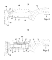
- a generally designated by the reference numeral 10 in the drawing shaft system for a shoulder-mounted weapon, such as a rifle or a shotgun for sports and hunting purposes or a combat weapon, comprises a pistol grip 12 as a support for the weapon system, not shown here, which optionally additionally covers the weapon system forward in the firing direction, a centerpiece 14 as a support for a height and side adjustable cheekpiece 15 and for a pivotable and longitudinal to the firing direction S adjustable shaft cap unit 16 or more, not shown here, fixed to the rear center of the rigid shaft cap units.
- the known adjustment means of the cheekpiece 15 are not shown in detail and comprise fastening tabs 18 and 19 designed as guide members, which can be fixed in the respective adjustment position via screw members 20, 21.
- the in a known manner multi-part formed Schaftkappenech 16 is hinged to a toothed and slidably mounted in the middle piece 14 telescopic tube 23, and at the end facing away from the weft direction S of the weapon system end.
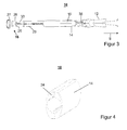
- the telescopic tube 23 can be axially adjusted by means of a guide plate 24 which is screwed in at the rear on the center piece and thus can be clamped, provided with a groove (see FIG FIG. 4 ).
- the shaft cap unit 16 itself has a pitch fork 33 rotatably mounted in the telescopic tube 23, a pivot plate (fork) 25 mounted pivotably on the pitch fork 33, and a shoulder plate 27 adjustably connected to an adjustment plate 26, which can be braced with one another via screw members.
- the screw members 30,31 engage in the toothing 34 of the telescope tube 23 a.
- the pistol grip 12 engages with a projection 35 in a corresponding opening 36 of the middle piece 14 on the shoulder cap unit (shoulder cap) 16 facing away, so the weft direction S facing side and is firmly but releasably braced with the center piece 14 by means of a screw 38.
- the weapon can be adjusted and adjusted with respect to their shank quickly and easily to the respective shooter.
- the geometric design of the handle and attachment elements, in particular of cheek piece 15 and butt plate unit 16, can be designed differently with respect to their aesthetic impression.
Abstract
Description
Die Erfindung betrifft ein Schaftsystem für eine schultergestützte Waffe, deren Schaft zum Halten und Stützen einen Pistolengriff, eine mindestens nach Seite und Höhe einstellbare Schaftbacke sowie eine schwenkbare und längsverstellbare Schaftkappe umfasst.The invention relates to a shaft system for a shoulder-mounted weapon, the shaft for holding and supporting a pistol grip, an adjustable at least side and height cheekpiece and a pivotable and longitudinally adjustable butt plate.
Solche vielfach bekannten für Rechts- und Linksschützen ausgebildete Schaftsysteme dienen dem Zweck, die Waffe den anatomischen Verhältnissen des jeweiligen Schützen anpassen zu können, was für das Anvisieren eines Ziels auch für Sportschützen von großem Vorteil ist.Such often known trained for right and left shooters shaft systems serve the purpose of being able to adapt the weapon to the anatomical conditions of the respective shooter, which is for the targeting of a target for shooters of great advantage.
Das Einstellen der Schaftbacken und Schaftkappen nach Seite und Höhe in Bezug auf das jeweilige Schafthauptteil erfolgt in der Regel über verstellbar und festschraubbar ausgebildete, mit Befestigungslaschen zusammenwirkende Führungsglieder, während für die Abstandseinstellung der Schaftkappe feststellbare Abstandsschrauben dienen; vgl. z.B.
Infolge der Vielzahl der hierfür benötigten, unterschiedlichst ausgebildeten Bauteile sind solche Schaftsysteme nicht flexibel genug und oft unhandlich sowie teuer in der Herstellung, kompliziert in ihrer Montage und dem Service. Auch lässt die Abstandseinstellung vor allem infolge der bisher nur möglichen geringen Abstandsänderungen, insbesondere für die Sportschützen Wünsche offen.Due to the large number of components required for this purpose, the most varied components are such shaft systems are not flexible enough and often unwieldy and expensive to manufacture, complicated in their installation and service. Also, the distance adjustment is mainly due to the previously possible only small changes in distance, especially for the shooter wishes.
Hier setzt nun die Erfindung ein, deren Aufgabe es ist, solche Schaftsysteme zu vereinfachen und insbesondere die vorgesehenen Abstandsänderungen zu vergrößern, um den stark unterschiedlichen Armlängen und Schulterformen der Schützen besser als bisher Rechnung tragen zu können.This is where the invention begins, the task of which is to simplify such shaft systems and, in particular, to increase the distance changes provided in order to better take account of the greatly differing arm lengths and shoulder shapes of the shooters.
Ausgehend von einem Schaftsystem für eine schultergestützte Waffe, deren das Waffensystem aufnehmender Schaft zum Halten und Stützen einen Pistolengriff, eine mindestens nach Seite und Höhe einstellbare Schaftbacke sowie eine schwenkbare und längsverstellbare Schaftkappe umfasst, wird diese Aufgabe nun erfindungsgemäß durch die kennzeichnenden Merkmale des Patentanspruchs 1 gelöst.Starting with a shoulder system for a shoulder-mounted weapon, its weapon system receiving shaft for holding and supporting a pistol grip, at least includes side and height adjustable cheek piece and a pivotable and longitudinally adjustable butt plate, this object is achieved according to the invention by the characterizing features of claim 1.
Weitere Merkmale der Erfindung ergeben sich aus den Unteransprüchen.Further features of the invention will become apparent from the dependent claims.
Die erfindungsgemäße Ausgestaltung des neuen Schaftsystems ersetzt den bisherigen Schafthauptteil durch ein zentrales Mittelstück für den Anbau aller wesentlichen Teile des Schaftsystems. Hierbei dient der Pistolengriff als Verbindungsmittel zwischen dem Waffensystem und dem Mittelstück, das auf seiner Oberseite die höhen- und seitenverstellbaren Schaftbacken trägt. Die Ausbildung des Trägers der drehbeweglich, schwenkbar und jeweils feststellbar gelagerten Schaftkappe als gezahntes oder mit einer Führungsrolle versehenes Teleskoprohr, das in das Mittelstück ein- und ausschiebbar ist sowie mit diesem über Klemmmittel verspannbar ist, ermöglicht auf einfache und sichere Weise eine weit größere Abstandsanpassung der Schaftkappe des Schaftsystems an die körperlichen Gegebenheiten des die Waffe gebrauchenden Schützen. Darüber hinaus ermöglicht die erfindungsgemäße Ausbildung eine einfache Herstellung, flexible Auslegung, Montage und Wartung des neuen Schaftsystems.The inventive design of the new shaft system replaces the previous shaft main part by a central center piece for the cultivation of all essential parts of the shaft system. Here, the pistol grip serves as a connecting means between the weapon system and the center piece, which carries on its upper side the height and side adjustable cheek plates. The formation of the carrier of the rotatably, pivotally and respectively lockably mounted butt plate as a toothed or provided with a guide telescopic tube, which is in and pushed out of the middle piece with this is clamped by clamping means allows a simple and safe way, a far greater distance adjustment of Butt plate of the shaft system to the physical conditions of the shooter using the weapon. In addition, the inventive design allows for easy production, flexible design, installation and maintenance of the new shaft system.
Die Erfindung wird nachfolgend nun anhand der mehr oder minder schematischen Darstellung eines Ausführungsbeispiels beschrieben.The invention will now be described with reference to the more or less schematic representation of an embodiment.
-
Figur 1 eine Ansicht des Schaftsystems von der Seite,FIG. 1 a view of the shaft system from the side, -
Figur 2 einen Schnitt durch die rechte Seite des Schaftsystems nachFigur 1 ,FIG. 2 a section through the right side of the shaft system afterFIG. 1 . -
Figur 3 eine Ansicht des Schaftsystems von oben, undFIG. 3 a view of the shaft system from above, and -
Figur 4 eine perspektivische Teilansicht des Schaftsystems.FIG. 4 a partial perspective view of the shaft system.
Ein in der Zeichnung insgesamt mit der Bezugsziffer 10 bezeichnetes Schaftsystem für eine schultergestützte Waffe, z.B. eine Büchse oder eine Flinte für Sport- und Jagdzwecke oder eine Kampfwaffe, umfasst einen Pistolengriff 12 als Träger für das hier nicht dargestellte Waffensystem, der gegebenenfalls das Waffensystem nach vorne in Schussrichtung zusätzlich abdeckt, ein Mittelstück 14 als Träger für eine nach Höhe und Seite verstellbare Schaftbacke 15 sowie für eine schwenkbar und längs zur Schussrichtung S verstellbare Schaftkappeneinheit 16 oder weitere, hier nicht abgebildete, am Mittelstück hinten befestigte starre Schaftkappeneinheiten.A generally designated by the
Die an sich bekannten Verstellmittel der Schaftbacke 15 sind nicht näher dargestellt und umfassen als Führungsglieder ausgebildete Befestigungslaschen 18 und 19, die über Schraubglieder 20,21 in die jeweilige Einstelllage feststellbar sind.The known adjustment means of the
Die in bekannter Weise mehrteilig ausgebildete Schaftkappeneinheit 16 ist an einer gezahnten und verschiebbar im Mittelstück 14 gelagerten Teleskoprohr 23 angelenkt, und zwar an dem der Schussrichtung S des Waffensystems abgewandten Ende. Das Teleskoprohr 23 lässt sich durch ein hinten am Mittelstück eingeschraubtes und somit festklemmbares, mit einer Nut versehenen Führungsplatte 24 axial justieren (siehe
Zur Einstellung der Schaftlänge greifen die Schraubglieder 30,31 in die Verzahnung 34 des Telekoprohres 23 ein. Um die Schaftlänge ohne zusätzliches Werkzeug mit wenigen Handgriffen verstellen zu können, kann auch alternativ ein im hinteren unterem Bereich des Mittelstückes 14 angeordneter, hier nicht dargestellter aber an sich bekannter schwenkbarer Hebel, zur Klemmung dienen.To adjust the shaft length, the
Alternativ kann ein entgegen der Schussrichtung am Mittelstück hinten anschraubbares, nicht verstellbares Schaftabschlussstück als kostengünstigere und gewichtsmäßig leichtere Lösung dienen.Alternatively, a counter to the weft direction on the rear center screwed, non-adjustable Schaftabschlussstück serve as a cheaper and lighter in weight solution.
Der Pistolengriff 12 greift mit einem Ansatz 35 in eine entsprechende Öffnung 36 des Mittelstückes 14 an der der Schulterkappeneinheit (Schulterkappe) 16 abgewandten, also der Schussrichtung S zugewandten, Seite ein und ist mit dem Mittelstück 14 mittels einer Schraube 38 fest aber lösbar verspannt.The
Mit dem vorstehend beschriebenen Schaftsystem kann die Waffe bezüglich ihres Schaftes schnell und einfach auf den jeweiligen Schützen individuell abgestimmt und eingestellt werden. Die geometrische Ausbildung der Griff- und Anbauelemente, insbesondere von Schaftbacke 15 und Schaftkappeneinheit 16, kann dabei unterschiedlich im Hinblick auf deren ästhetischen Eindruck gestaltet sein. Um das Schaftsystem mit wenigen Handgriffen mit dem nicht dargestellten Waffensystem verspannen zu können, wird über einen an der Unterseite des Mittelstückes 14 angeordneten, hier nicht dargestellten aber an sich bekannten Hebel, eine Zugstange mit einer daran befestigten Spannzange nach hinten - entgegen dem Pfeil S gezogen, so dass durch Eingriff der Spannzange in ein Gegenstück an dem Waffensystem das Schaftsystem 10 mit der Waffe verspannt werden kann.With the shaft system described above, the weapon can be adjusted and adjusted with respect to their shank quickly and easily to the respective shooter. The geometric design of the handle and attachment elements, in particular of
Claims (7)
Applications Claiming Priority (1)
| Application Number | Priority Date | Filing Date | Title |
|---|---|---|---|
| DE102009010768A DE102009010768B4 (en) | 2009-02-26 | 2009-02-26 | Shaft system for a shoulder-mounted weapon |
Publications (4)
| Publication Number | Publication Date |
|---|---|
| EP2224202A2 true EP2224202A2 (en) | 2010-09-01 |
| EP2224202A3 EP2224202A3 (en) | 2012-05-23 |
| EP2224202B1 EP2224202B1 (en) | 2016-05-11 |
| EP2224202B8 EP2224202B8 (en) | 2016-12-07 |
Family
ID=41728237
Family Applications (1)
| Application Number | Title | Priority Date | Filing Date |
|---|---|---|---|
| EP10154678.6A Active EP2224202B8 (en) | 2009-02-26 | 2010-02-25 | Stocksystem for a shoulder fire arm |
Country Status (4)
| Country | Link |
|---|---|
| US (1) | US8381427B2 (en) |
| EP (1) | EP2224202B8 (en) |
| DE (1) | DE102009010768B4 (en) |
| ES (1) | ES2586460T3 (en) |
Cited By (6)
| Publication number | Priority date | Publication date | Assignee | Title |
|---|---|---|---|---|
| DE102011084430A1 (en) * | 2011-10-13 | 2013-04-18 | Heckler & Koch Gmbh | Shoulder support for a firearm |
| ITUB20152572A1 (en) * | 2015-07-28 | 2017-01-28 | Giovanni Nardi | ADJUSTABLE SOCCER TYPE PERFECTED FOR FIRE WEAPON AND FIRE WEAPON INCLUDING THE ADJUSTABLE SOCCER |
| EP3343165A1 (en) * | 2016-12-27 | 2018-07-04 | Futurmec S.R.L. | Stock for shotgun |
| WO2019165485A1 (en) * | 2018-03-01 | 2019-09-06 | Steyr Arms Gmbh | Stock for a portable firearm |
| IT202000017377A1 (en) * | 2020-07-16 | 2022-01-16 | Giuseppe Palumbo | RIFLE STOCK DEVICE |
| IT202000030851A1 (en) * | 2020-12-15 | 2022-06-15 | Giuseppe Palumbo | RIFLE STOCK DEVICE |
Families Citing this family (36)
| Publication number | Priority date | Publication date | Assignee | Title |
|---|---|---|---|---|
| US8631601B2 (en) * | 2007-10-05 | 2014-01-21 | Colt Defense, Llc | Automatic or semiautomatic rifle with folding clamshell buttstock |
| SG193880A1 (en) | 2008-09-12 | 2013-10-30 | Colt Defense Llc | Firearm having a hybrid indirect gas operating system |
| US20120036757A1 (en) * | 2010-08-12 | 2012-02-16 | Larue Mark C | Gun-stock riser for AR15 type tactical firearm |
| US8844185B2 (en) | 2012-08-27 | 2014-09-30 | Ra Brands, L.L.C. | Buttstock assembly |
| USD704294S1 (en) | 2012-09-19 | 2014-05-06 | Ra Brands, L.L.C. | Buttstock |
| US9664478B2 (en) * | 2012-10-13 | 2017-05-30 | Rmdi, Llc | Adjustable firearm stock |
| US8776423B2 (en) * | 2012-10-22 | 2014-07-15 | Battleline Industries, Inc. | Adjustment mechanism for handheld weapons |
| US9568273B2 (en) * | 2012-11-29 | 2017-02-14 | Alan T. Thordsen | Sporterized firearm stocks and methods thereof |
| US9823042B2 (en) | 2012-11-29 | 2017-11-21 | Alan T. Thordsen | Adaptable sporterized firearm stocks and methods thereof |
| US20140196345A1 (en) * | 2013-01-16 | 2014-07-17 | Sig Sauer, Inc. | Foldable stock retention assembly |
| US8955245B2 (en) * | 2013-03-15 | 2015-02-17 | Ati Ip, Llc | Adjustable stock for a firearm |
| US9127905B2 (en) * | 2013-03-15 | 2015-09-08 | William Thomas Schreckenstein | Receiver spur for a firearm |
| US9364868B2 (en) | 2013-09-05 | 2016-06-14 | Federal Signal Corporation | Adjustable stock assembly for fluid spray gun and methods |
| US8984791B1 (en) * | 2014-01-08 | 2015-03-24 | Jimi Leslie | Adjustable gun stock assembly with modular accessories |
| US9109855B1 (en) * | 2014-04-18 | 2015-08-18 | Bravo Company USA, Inc. | Modular buttstock assembly |
| US9488435B1 (en) | 2015-05-04 | 2016-11-08 | Magpul Industries Corp. | Stock assembly |
| US9523552B2 (en) | 2015-05-04 | 2016-12-20 | Magpul Industries Corp. | Anti-rotational quick disconnect mount for a firearm |
| US9404708B1 (en) | 2015-06-30 | 2016-08-02 | Magpul Industries Corp. | Stock for a firearm |
| USD779018S1 (en) | 2016-01-11 | 2017-02-14 | Magpul Industries Corporation | Adjustable buttstock for a firearm |
| USD781392S1 (en) * | 2016-01-11 | 2017-03-14 | Magpul Industries Corporation | Adjustable buttstock for a firearm |
| USD804602S1 (en) | 2016-01-12 | 2017-12-05 | Magpul Industries Corp. | Firearm stock |
| ES2582980B1 (en) * | 2016-03-07 | 2017-04-11 | José Manuel DÍAZ AJA | ADJUSTABLE SHOULDER SUPPORT HEAD FOR FIREARMS |
| CN106204636B (en) | 2016-06-27 | 2019-03-22 | 北京大学深圳研究生院 | Video foreground extracting method based on monitor video |
| USD819769S1 (en) * | 2016-10-12 | 2018-06-05 | Nathaniel D. Stevens | Rifle stock cover |
| US10215526B2 (en) * | 2017-01-13 | 2019-02-26 | Sig Sauer, Inc. | Stock |
| US9915498B1 (en) * | 2017-01-16 | 2018-03-13 | Spuhr | Dalby AB | Length adjustable butt pad assembly |
| US10458746B2 (en) * | 2017-08-21 | 2019-10-29 | Sig Sauer, Inc. | Adjustable cheek riser |
| US10228214B1 (en) | 2017-08-30 | 2019-03-12 | Robert L. Rich | Fixed stock adapter |
| US10788287B2 (en) | 2017-10-27 | 2020-09-29 | Sturm, Ruger & Company, Inc. | Adjustable stock for firearm |
| NO346779B1 (en) * | 2017-12-29 | 2022-12-27 | GRS Riflestocks AS | A modular stock for a firearm |
| US10551144B2 (en) * | 2018-01-03 | 2020-02-04 | 22 Evolutiion LLC | Firearm with combination extensible shoulder stock and receiver tube |
| USD872215S1 (en) | 2018-01-05 | 2020-01-07 | 22 Evolution Llc | Combination extensible firearm shoulder stock and receiver tube |
| USD891561S1 (en) | 2018-10-30 | 2020-07-28 | Sturm, Ruger & Company, Inc. | Buttstock for firearm |
| US11365952B2 (en) | 2019-08-16 | 2022-06-21 | Sig Sauer, Inc. | Firearm stock with adjustable butt plate and locking comb assembly |
| RU201091U1 (en) * | 2020-09-29 | 2020-11-26 | Николай Геннадьевич Пушкарёв | Small arms stock with adjustable pivoting cheek piece |
| RU206010U1 (en) * | 2021-04-14 | 2021-08-16 | Николай Геннадьевич Пушкарёв | Small arms stock with adjustable pivoting cheek piece |
Citations (2)
| Publication number | Priority date | Publication date | Assignee | Title |
|---|---|---|---|---|
| DE9411466U1 (en) | 1994-07-15 | 1994-11-10 | Westinger & Altenburger | Stock for a precision firearm with a cheek piece and / or a butt plate |
| DE102004057414A1 (en) | 2003-11-28 | 2005-06-30 | Rappenhöner, Hans Richard | Lock cap for firearm has lower part including turning lever able to turn and be displaced in lever holding part fitted with lever in middle part |
Family Cites Families (18)
| Publication number | Priority date | Publication date | Assignee | Title |
|---|---|---|---|---|
| DE1854723U (en) * | 1960-12-23 | 1962-07-05 | J G Anschuetz G M B H | SPORTS RIFLE. |
| US3137958A (en) * | 1962-10-29 | 1964-06-23 | Browning Ind Inc | Adjustable butt stock |
| DE8307047U1 (en) * | 1983-03-11 | 1983-07-14 | Carl Walther Gmbh, 7900 Ulm | CAP, ESPECIALLY FOR SPORTS RIFLES |
| US4896446A (en) * | 1989-07-10 | 1990-01-30 | G. Squared, Inc. | Buttplate and comb assembly for shoulder firearms |
| US5031348A (en) * | 1990-10-01 | 1991-07-16 | Carey Donald C | Gun stock assembly with coordinated comb and recoil |
| FR2686152B3 (en) * | 1992-01-13 | 1993-12-17 | Alonso Berbegal Jose | IMPROVED DEVICE FOR ALLOWING THE HINGE OF A HUNTING RIFLE. |
| US6651371B2 (en) * | 2001-06-25 | 2003-11-25 | Richard Mark Fitzpatrick | Modular gunstock |
| US7398616B1 (en) * | 2004-05-21 | 2008-07-15 | Robert Weir | Adjustable length heavy duty butt stock assembly for a firearm |
| US7024812B2 (en) * | 2004-06-03 | 2006-04-11 | Nelson James B | Gun stock pivot |
| DE102005004978B4 (en) * | 2005-02-04 | 2006-11-30 | S.A.T. Swiss Arms Technology Ag | Adjustable butt plate for a handgun |
| EP1748272A3 (en) * | 2005-07-26 | 2007-03-21 | T.D.I. Arms Ltd. | Telescoping firearm stock |
| US7805873B2 (en) * | 2005-11-08 | 2010-10-05 | Blackhawk Industries Product Group Unlimited Llc | Modular cheek rest and storage assembly |
| DE102006059914A1 (en) * | 2005-12-23 | 2007-07-05 | Rappenhöner, Hans Richard | Firearm stock for exchangeable fixing of bullet release system e.g. sports weapon has variable length stock main part which is longitudinally-extensible, handle, and cheek cap |
| US7930849B2 (en) * | 2006-03-11 | 2011-04-26 | Dick Abraham | Adjustable butt stock |
| JP4748366B2 (en) * | 2006-06-28 | 2011-08-17 | 豊和工業株式会社 | Gun telescopic stock |
| US7647719B2 (en) * | 2007-01-11 | 2010-01-19 | Magpul Industries Corp. | Gunstocks and adapters |
| US8312661B2 (en) * | 2008-07-18 | 2012-11-20 | Christopher Allen Ludlow | Folding rifle stock |
| US8087193B2 (en) * | 2009-03-26 | 2012-01-03 | Abrams Airborne Manufacturing, Inc. | Firearm buttstock assembly and method |
-
2009
- 2009-02-26 DE DE102009010768A patent/DE102009010768B4/en not_active Expired - Fee Related
-
2010
- 2010-02-25 US US12/713,028 patent/US8381427B2/en active Active
- 2010-02-25 EP EP10154678.6A patent/EP2224202B8/en active Active
- 2010-02-25 ES ES10154678.6T patent/ES2586460T3/en active Active
Patent Citations (2)
| Publication number | Priority date | Publication date | Assignee | Title |
|---|---|---|---|---|
| DE9411466U1 (en) | 1994-07-15 | 1994-11-10 | Westinger & Altenburger | Stock for a precision firearm with a cheek piece and / or a butt plate |
| DE102004057414A1 (en) | 2003-11-28 | 2005-06-30 | Rappenhöner, Hans Richard | Lock cap for firearm has lower part including turning lever able to turn and be displaced in lever holding part fitted with lever in middle part |
Cited By (9)
| Publication number | Priority date | Publication date | Assignee | Title |
|---|---|---|---|---|
| DE102011084430A1 (en) * | 2011-10-13 | 2013-04-18 | Heckler & Koch Gmbh | Shoulder support for a firearm |
| US9052155B2 (en) | 2011-10-13 | 2015-06-09 | Heckler & Koch Gmbh | Firearm |
| ITUB20152572A1 (en) * | 2015-07-28 | 2017-01-28 | Giovanni Nardi | ADJUSTABLE SOCCER TYPE PERFECTED FOR FIRE WEAPON AND FIRE WEAPON INCLUDING THE ADJUSTABLE SOCCER |
| WO2017017560A1 (en) * | 2015-07-28 | 2017-02-02 | Giovanni Nardi | Improved adjustable firearm butt and a firearm comprising said adjustable butt |
| EP3343165A1 (en) * | 2016-12-27 | 2018-07-04 | Futurmec S.R.L. | Stock for shotgun |
| US10337826B2 (en) | 2016-12-27 | 2019-07-02 | Futurmec S.R.L. | Stock for shotgun |
| WO2019165485A1 (en) * | 2018-03-01 | 2019-09-06 | Steyr Arms Gmbh | Stock for a portable firearm |
| IT202000017377A1 (en) * | 2020-07-16 | 2022-01-16 | Giuseppe Palumbo | RIFLE STOCK DEVICE |
| IT202000030851A1 (en) * | 2020-12-15 | 2022-06-15 | Giuseppe Palumbo | RIFLE STOCK DEVICE |
Also Published As
| Publication number | Publication date |
|---|---|
| DE102009010768A1 (en) | 2010-09-09 |
| EP2224202B1 (en) | 2016-05-11 |
| ES2586460T8 (en) | 2017-01-13 |
| EP2224202B8 (en) | 2016-12-07 |
| EP2224202A3 (en) | 2012-05-23 |
| DE102009010768B4 (en) | 2013-07-11 |
| US20100212205A1 (en) | 2010-08-26 |
| ES2586460T3 (en) | 2016-10-14 |
| US8381427B2 (en) | 2013-02-26 |
Similar Documents
| Publication | Publication Date | Title |
|---|---|---|
| EP2224202B1 (en) | Stocksystem for a shoulder fire arm | |
| AT506783B1 (en) | MOVABLE FURNITURE ACCESSORIES WITH RELING ADJUSTMENT | |
| EP2021727A1 (en) | Shoulder stock fastening | |
| EP2956732B1 (en) | Universal riflescope mount for hand-held weapons | |
| EP3134700A1 (en) | Support for the arm of a pistol shooter | |
| DE102009039669B4 (en) | Handgun | |
| DE637594C (en) | Portable firearm with a throwing tube for throwing bombs | |
| DE102013208770A1 (en) | Rifle, especially assault rifle | |
| DE102009023520B4 (en) | Holder for attachment for mounting on firearm with rail | |
| DE541130C (en) | Firearm in carriage with directional handles and shoulder piece | |
| DE2816128C2 (en) | Multi-barreled rifle | |
| DE3128848C2 (en) | ||
| AT505964B1 (en) | mortar | |
| DE218425C (en) | ||
| EP2569096B1 (en) | Spray lance with adjustable length and axially adjustable handle | |
| DE102015109535B3 (en) | Adjustable attachment of a forend raiser of a pneumatic rifle and pneumatic rifle | |
| DE79418C (en) | Rifle support carried by the waist strap for use in hands-free attack while standing or kneeling | |
| DE461988C (en) | Method for manufacturing pipe elbows from malleable material in a bending device using mandrels | |
| DE4030199C2 (en) | ||
| DE909547C (en) | Visor tracking, especially for anti-aircraft mounts | |
| DE8605954U1 (en) | Device for adjusting means on gun barrels | |
| DE35473C (en) | Gun for ship guns | |
| DE27204C (en) | Sighting device for rifles | |
| DE86365C (en) | ||
| DE3148554A1 (en) | RIFLES FOR SPORTS |
Legal Events
| Date | Code | Title | Description |
|---|---|---|---|
| PUAI | Public reference made under article 153(3) epc to a published international application that has entered the european phase |
Free format text: ORIGINAL CODE: 0009012 |
|
| AK | Designated contracting states |
Kind code of ref document: A2 Designated state(s): AT BE BG CH CY CZ DE DK EE ES FI FR GB GR HR HU IE IS IT LI LT LU LV MC MK MT NL NO PL PT RO SE SI SK SM TR |
|
| AX | Request for extension of the european patent |
Extension state: AL BA RS |
|
| PUAL | Search report despatched |
Free format text: ORIGINAL CODE: 0009013 |
|
| AK | Designated contracting states |
Kind code of ref document: A3 Designated state(s): AT BE BG CH CY CZ DE DK EE ES FI FR GB GR HR HU IE IS IT LI LT LU LV MC MK MT NL NO PL PT RO SE SI SK SM TR |
|
| AX | Request for extension of the european patent |
Extension state: AL BA RS |
|
| RIC1 | Information provided on ipc code assigned before grant |
Ipc: F41C 23/04 20060101ALN20120416BHEP Ipc: F41C 23/14 20060101AFI20120416BHEP |
|
| 17P | Request for examination filed |
Effective date: 20121031 |
|
| 17Q | First examination report despatched |
Effective date: 20131015 |
|
| GRAP | Despatch of communication of intention to grant a patent |
Free format text: ORIGINAL CODE: EPIDOSNIGR1 |
|
| RIC1 | Information provided on ipc code assigned before grant |
Ipc: F41C 23/04 20060101ALN20151119BHEP Ipc: F41C 23/14 20060101AFI20151119BHEP |
|
| INTG | Intention to grant announced |
Effective date: 20151211 |
|
| RIC1 | Information provided on ipc code assigned before grant |
Ipc: F41C 23/14 20060101AFI20151202BHEP Ipc: F41C 23/04 20060101ALN20151202BHEP |
|
| GRAS | Grant fee paid |
Free format text: ORIGINAL CODE: EPIDOSNIGR3 |
|
| GRAA | (expected) grant |
Free format text: ORIGINAL CODE: 0009210 |
|
| AK | Designated contracting states |
Kind code of ref document: B1 Designated state(s): AT BE BG CH CY CZ DE DK EE ES FI FR GB GR HR HU IE IS IT LI LT LU LV MC MK MT NL NO PL PT RO SE SI SK SM TR |
|
| REG | Reference to a national code |
Ref country code: GB Ref legal event code: FG4D Free format text: NOT ENGLISH |
|
| REG | Reference to a national code |
Ref country code: CH Ref legal event code: EP |
|
| REG | Reference to a national code |
Ref country code: AT Ref legal event code: REF Ref document number: 798995 Country of ref document: AT Kind code of ref document: T Effective date: 20160515 |
|
| REG | Reference to a national code |
Ref country code: IE Ref legal event code: FG4D Free format text: LANGUAGE OF EP DOCUMENT: GERMAN |
|
| REG | Reference to a national code |
Ref country code: DE Ref legal event code: R096 Ref document number: 502010011634 Country of ref document: DE |
|
| REG | Reference to a national code |
Ref country code: LT Ref legal event code: MG4D |
|
| REG | Reference to a national code |
Ref country code: NL Ref legal event code: MP Effective date: 20160511 |
|
| REG | Reference to a national code |
Ref country code: ES Ref legal event code: FG2A Ref document number: 2586460 Country of ref document: ES Kind code of ref document: T3 Effective date: 20161014 |
|
| PG25 | Lapsed in a contracting state [announced via postgrant information from national office to epo] |
Ref country code: LT Free format text: LAPSE BECAUSE OF FAILURE TO SUBMIT A TRANSLATION OF THE DESCRIPTION OR TO PAY THE FEE WITHIN THE PRESCRIBED TIME-LIMIT Effective date: 20160511 Ref country code: NO Free format text: LAPSE BECAUSE OF FAILURE TO SUBMIT A TRANSLATION OF THE DESCRIPTION OR TO PAY THE FEE WITHIN THE PRESCRIBED TIME-LIMIT Effective date: 20160811 Ref country code: NL Free format text: LAPSE BECAUSE OF FAILURE TO SUBMIT A TRANSLATION OF THE DESCRIPTION OR TO PAY THE FEE WITHIN THE PRESCRIBED TIME-LIMIT Effective date: 20160511 Ref country code: FI Free format text: LAPSE BECAUSE OF FAILURE TO SUBMIT A TRANSLATION OF THE DESCRIPTION OR TO PAY THE FEE WITHIN THE PRESCRIBED TIME-LIMIT Effective date: 20160511 |
|
| PG25 | Lapsed in a contracting state [announced via postgrant information from national office to epo] |
Ref country code: GR Free format text: LAPSE BECAUSE OF FAILURE TO SUBMIT A TRANSLATION OF THE DESCRIPTION OR TO PAY THE FEE WITHIN THE PRESCRIBED TIME-LIMIT Effective date: 20160812 Ref country code: PT Free format text: LAPSE BECAUSE OF FAILURE TO SUBMIT A TRANSLATION OF THE DESCRIPTION OR TO PAY THE FEE WITHIN THE PRESCRIBED TIME-LIMIT Effective date: 20160912 Ref country code: HR Free format text: LAPSE BECAUSE OF FAILURE TO SUBMIT A TRANSLATION OF THE DESCRIPTION OR TO PAY THE FEE WITHIN THE PRESCRIBED TIME-LIMIT Effective date: 20160511 Ref country code: SE Free format text: LAPSE BECAUSE OF FAILURE TO SUBMIT A TRANSLATION OF THE DESCRIPTION OR TO PAY THE FEE WITHIN THE PRESCRIBED TIME-LIMIT Effective date: 20160511 Ref country code: LV Free format text: LAPSE BECAUSE OF FAILURE TO SUBMIT A TRANSLATION OF THE DESCRIPTION OR TO PAY THE FEE WITHIN THE PRESCRIBED TIME-LIMIT Effective date: 20160511 |
|
| PG25 | Lapsed in a contracting state [announced via postgrant information from national office to epo] |
Ref country code: CZ Free format text: LAPSE BECAUSE OF FAILURE TO SUBMIT A TRANSLATION OF THE DESCRIPTION OR TO PAY THE FEE WITHIN THE PRESCRIBED TIME-LIMIT Effective date: 20160511 Ref country code: DK Free format text: LAPSE BECAUSE OF FAILURE TO SUBMIT A TRANSLATION OF THE DESCRIPTION OR TO PAY THE FEE WITHIN THE PRESCRIBED TIME-LIMIT Effective date: 20160511 Ref country code: RO Free format text: LAPSE BECAUSE OF FAILURE TO SUBMIT A TRANSLATION OF THE DESCRIPTION OR TO PAY THE FEE WITHIN THE PRESCRIBED TIME-LIMIT Effective date: 20160511 Ref country code: SK Free format text: LAPSE BECAUSE OF FAILURE TO SUBMIT A TRANSLATION OF THE DESCRIPTION OR TO PAY THE FEE WITHIN THE PRESCRIBED TIME-LIMIT Effective date: 20160511 Ref country code: EE Free format text: LAPSE BECAUSE OF FAILURE TO SUBMIT A TRANSLATION OF THE DESCRIPTION OR TO PAY THE FEE WITHIN THE PRESCRIBED TIME-LIMIT Effective date: 20160511 |
|
| REG | Reference to a national code |
Ref country code: DE Ref legal event code: R097 Ref document number: 502010011634 Country of ref document: DE |
|
| REG | Reference to a national code |
Ref country code: FR Ref legal event code: PLFP Year of fee payment: 8 |
|
| PG25 | Lapsed in a contracting state [announced via postgrant information from national office to epo] |
Ref country code: SM Free format text: LAPSE BECAUSE OF FAILURE TO SUBMIT A TRANSLATION OF THE DESCRIPTION OR TO PAY THE FEE WITHIN THE PRESCRIBED TIME-LIMIT Effective date: 20160511 Ref country code: PL Free format text: LAPSE BECAUSE OF FAILURE TO SUBMIT A TRANSLATION OF THE DESCRIPTION OR TO PAY THE FEE WITHIN THE PRESCRIBED TIME-LIMIT Effective date: 20160511 |
|
| PLBE | No opposition filed within time limit |
Free format text: ORIGINAL CODE: 0009261 |
|
| STAA | Information on the status of an ep patent application or granted ep patent |
Free format text: STATUS: NO OPPOSITION FILED WITHIN TIME LIMIT |
|
| 26N | No opposition filed |
Effective date: 20170214 |
|
| PG25 | Lapsed in a contracting state [announced via postgrant information from national office to epo] |
Ref country code: BE Free format text: LAPSE BECAUSE OF NON-PAYMENT OF DUE FEES Effective date: 20170228 Ref country code: SI Free format text: LAPSE BECAUSE OF FAILURE TO SUBMIT A TRANSLATION OF THE DESCRIPTION OR TO PAY THE FEE WITHIN THE PRESCRIBED TIME-LIMIT Effective date: 20160511 |
|
| PG25 | Lapsed in a contracting state [announced via postgrant information from national office to epo] |
Ref country code: MC Free format text: LAPSE BECAUSE OF FAILURE TO SUBMIT A TRANSLATION OF THE DESCRIPTION OR TO PAY THE FEE WITHIN THE PRESCRIBED TIME-LIMIT Effective date: 20160511 |
|
| REG | Reference to a national code |
Ref country code: CH Ref legal event code: PL |
|
| PG25 | Lapsed in a contracting state [announced via postgrant information from national office to epo] |
Ref country code: LI Free format text: LAPSE BECAUSE OF NON-PAYMENT OF DUE FEES Effective date: 20170228 Ref country code: CH Free format text: LAPSE BECAUSE OF NON-PAYMENT OF DUE FEES Effective date: 20170228 |
|
| REG | Reference to a national code |
Ref country code: IE Ref legal event code: MM4A |
|
| PG25 | Lapsed in a contracting state [announced via postgrant information from national office to epo] |
Ref country code: LU Free format text: LAPSE BECAUSE OF NON-PAYMENT OF DUE FEES Effective date: 20170225 |
|
| REG | Reference to a national code |
Ref country code: BE Ref legal event code: MM Effective date: 20170228 |
|
| REG | Reference to a national code |
Ref country code: FR Ref legal event code: PLFP Year of fee payment: 9 |
|
| PG25 | Lapsed in a contracting state [announced via postgrant information from national office to epo] |
Ref country code: IE Free format text: LAPSE BECAUSE OF NON-PAYMENT OF DUE FEES Effective date: 20170225 |
|
| REG | Reference to a national code |
Ref country code: AT Ref legal event code: MM01 Ref document number: 798995 Country of ref document: AT Kind code of ref document: T Effective date: 20170225 |
|
| PG25 | Lapsed in a contracting state [announced via postgrant information from national office to epo] |
Ref country code: AT Free format text: LAPSE BECAUSE OF NON-PAYMENT OF DUE FEES Effective date: 20170225 |
|
| PG25 | Lapsed in a contracting state [announced via postgrant information from national office to epo] |
Ref country code: MT Free format text: LAPSE BECAUSE OF FAILURE TO SUBMIT A TRANSLATION OF THE DESCRIPTION OR TO PAY THE FEE WITHIN THE PRESCRIBED TIME-LIMIT Effective date: 20160511 |
|
| PG25 | Lapsed in a contracting state [announced via postgrant information from national office to epo] |
Ref country code: HU Free format text: LAPSE BECAUSE OF FAILURE TO SUBMIT A TRANSLATION OF THE DESCRIPTION OR TO PAY THE FEE WITHIN THE PRESCRIBED TIME-LIMIT; INVALID AB INITIO Effective date: 20100225 |
|
| PG25 | Lapsed in a contracting state [announced via postgrant information from national office to epo] |
Ref country code: BG Free format text: LAPSE BECAUSE OF FAILURE TO SUBMIT A TRANSLATION OF THE DESCRIPTION OR TO PAY THE FEE WITHIN THE PRESCRIBED TIME-LIMIT Effective date: 20160511 |
|
| PG25 | Lapsed in a contracting state [announced via postgrant information from national office to epo] |
Ref country code: CY Free format text: LAPSE BECAUSE OF NON-PAYMENT OF DUE FEES Effective date: 20160511 |
|
| PG25 | Lapsed in a contracting state [announced via postgrant information from national office to epo] |
Ref country code: MK Free format text: LAPSE BECAUSE OF FAILURE TO SUBMIT A TRANSLATION OF THE DESCRIPTION OR TO PAY THE FEE WITHIN THE PRESCRIBED TIME-LIMIT Effective date: 20160511 |
|
| PGFP | Annual fee paid to national office [announced via postgrant information from national office to epo] |
Ref country code: TR Payment date: 20200221 Year of fee payment: 11 |
|
| PG25 | Lapsed in a contracting state [announced via postgrant information from national office to epo] |
Ref country code: IS Free format text: LAPSE BECAUSE OF FAILURE TO SUBMIT A TRANSLATION OF THE DESCRIPTION OR TO PAY THE FEE WITHIN THE PRESCRIBED TIME-LIMIT Effective date: 20160911 |
|
| PGFP | Annual fee paid to national office [announced via postgrant information from national office to epo] |
Ref country code: FR Payment date: 20230221 Year of fee payment: 14 Ref country code: ES Payment date: 20230301 Year of fee payment: 14 |
|
| PGFP | Annual fee paid to national office [announced via postgrant information from national office to epo] |
Ref country code: IT Payment date: 20230228 Year of fee payment: 14 Ref country code: GB Payment date: 20230221 Year of fee payment: 14 Ref country code: DE Payment date: 20230216 Year of fee payment: 14 |